JP4046865B2 - Crystal orientation measuring apparatus and crystal orientation measuring method - Google Patents
Crystal orientation measuring apparatus and crystal orientation measuring method Download PDFInfo
- Publication number
- JP4046865B2 JP4046865B2 JP25152398A JP25152398A JP4046865B2 JP 4046865 B2 JP4046865 B2 JP 4046865B2 JP 25152398 A JP25152398 A JP 25152398A JP 25152398 A JP25152398 A JP 25152398A JP 4046865 B2 JP4046865 B2 JP 4046865B2
- Authority
- JP
- Japan
- Prior art keywords
- measurement
- coordinates
- crystal
- axis
- subject
- Prior art date
- Legal status (The legal status is an assumption and is not a legal conclusion. Google has not performed a legal analysis and makes no representation as to the accuracy of the status listed.)
- Expired - Lifetime
Links
Images


Landscapes
- Length-Measuring Devices Using Wave Or Particle Radiation (AREA)
- Analysing Materials By The Use Of Radiation (AREA)
Description
【0001】
【発明の属する技術分野】
本発明は、例えばシリコンや水晶等の単結晶試料の結晶方位をX線回折を利用して測定する結晶方位測定装置及び結晶方位測定方法に関する。
【0002】
【従来の技術】
シリコンや水晶等の単結晶を半導体や発振体等の工業製品として使用するためには、その表面が結晶格子面に対して特定の角度になるように切断する必要がある。そのために、試料の結晶格子面を知る必要があるが、最も一般的に用いられている結晶の格子面測定方法は、X線回折を利用するものである。図32は、このX線回折を利用した試料の格子面測定方法を示している。つまり、試料200に対して単一波長のX線を入射させるとき、X線の入射角がθ0 になると、そのX線が原子Aにより回折される。この時の角度を回折角度(ブラッグ角)と称し、その角度θ0 は、次の式(1)で求められる。
【0003】
θ0 =arcsin(nλ/2d) …(1)
n;1,2,3,…の自然数
λ;X線の波長(既知)
d;格子面間隔(既知)
このように、θ0 が計算できるので、X線の入射角方向を変えながら回折X線を測定することで結晶の方位を測定することができる。
【0004】
ここで、円筒状の単結晶インゴットを厚さ0.3mm程度の円板(ウェーハ)に加工する工程で結晶方位測定は通常2度に分けて行われる。まず、単結晶インゴットを円筒状に研削し側面(円筒面)に対し第1の結晶方位の測定を行い側面に軸に沿ったオリエンテーションフラット面(OF面)あるいはV溝を加工し方位の目印とする。次に円筒軸に直角に端部を切断し、この試断面に対し第2の結晶方位の測定を行い定められた結晶面と試断面の傾斜角を求め、結晶面と平行にあるいは所定の角度をなすようにスライシングマシンでウェーハに加工する。ウェーハは周囲のOF面により周方向の結晶方位がわかる。
【0005】
上記の第1の円筒面の結晶方位測定を行う結晶方位測定装置としては、例えば、図33に示すようなものがある(特開昭62−116243号公報)。単結晶インゴット205はローラ203a,203bで保持され、ハンドル204でローラ203a,203bを回転させることでその軸回りに回転させられる。この軸に直交する平面内でX線投光器208からX線ビーム210aを結晶表面C点に当て回折X線ビーム210bをX線受光器209で測定する。X線投光器208とX線受光器209はC点を中心に2αの角度をなすよう台座207に固定されている。αは結晶面で決まる回折角をθ0 としてα=90゜−θ0 の値に設定される。単結晶インゴット205を回転させると、結晶面の法線の方向がX線ビーム210aとαの角度(図のCD方向)になったとき、X線受光器209の出力が最大となり結晶面の法線方向がわかる。マーカーで印をつけ側面にOF面の加工を行う。
【0006】
第2の試断面の結晶方位測定を行う結晶方位測定装置としては、例えば、図34に示すようなものがある(特開平2−31145号公報)。結晶303は、その試断面を下方に向けてヘッド302に取付けられ、ヘッド302は測定時、ヘッド回転軸318で回転され、X線回折位置Aにセットされる。結晶方位測定装置310は、本体314に取付けられたX線発生器311とX線検出器312により試断面にX線を照射し、回折X線を測定する。照射角は水平面に対し結晶面で決まる回折角、θ0 に設定される。本体314は下部に回転支持ベース316がありスライシングマシン301に取り付いた案内板317の上で水平面内で90゜回転でき、回折測定面をx,y方向に切換えできる。まず、図のように回折測定面をy方向に設定し、y方向微調ツマミ321で結晶303をy方向に傾斜させながらX線検出器312の出力ピークを探し、固定する。次にx方向に切換え、x方向微調ツマミ320で同様にx方向の調整を行う。これにより結晶面が水平になるように結晶303が傾斜される。次にヘッド302を90゜回転させ、カッタ位置Bに設定し、結晶303を切断カッタ304側に送り出し薄板に切断する。切断カッタ304は水平に固定されているので結晶面に沿って切断できる。
【0007】
この試断面の結晶方位測定装置の例は、スライシングマシンと一体で、直接傾斜角の調整を行うタイプであるが、別置きで傾斜角の測定のみを行うこともできる。第1の円筒面の結晶方位測定と第2の試断面の結晶方位測定は同一の装置で配置を変えて2度に分けて測定することもできる。
【0008】
【発明が解決しようとする課題】
従来は、単結晶インゴットのOF面の加工用の結晶方位測定とスライス加工用の結晶方位測定が別々の測定で行われていた。このために別々の装置が必要になるという問題点があった。また1台の装置で兼用する場合でも工程として2度の測定を必要とし効率が悪いという問題点があった。
【0009】
本発明は、上記に鑑みてなされたもので、円筒状結晶の側面からの測定のみでその法線が略円筒軸方向である所定の結晶面の方位を求めることができ、また、その円筒状結晶の側面に直交する方向の結晶面法線と円筒軸方向の結晶面法線とを1つの装置で求めることができる結晶方位測定装置及び結晶方位測定方法を提供することを目的とする。
【0010】
【課題を解決するための手段】
上記課題を解決するために、請求項1記載の結晶方位測定装置は、略円筒状結晶である被検体を保持する保持手段と、前記被検体の側面の略1点に向けてX線ビームを放射し回折された回折X線を検出することで前記側面に略直交する結晶面法線の方向を測定する測定部と、前記被検体もしくは前記測定部を略前記被検体の軸であるω軸の周りにω回転させるω回転機構と、このω回転における第1及び第2の位置でそれぞれ測定した互いに非平行な第1の結晶面法線h 1 及び第2の結晶面法線h 2 より前記ω軸に略平行な第3の結晶面法線h 0 を、
h 0 =±(h 1 ×h 2 )/√{1−(h 1 ・h 2 )^2}
(×はベクトル積、・は内積を示す)
なる数式に基づいて求めるデータ処理部とを有することを要旨とする。この構成により、測定部で、被検体の結晶面のうち、その法線がω軸に略直交する互いに非平行な第1及び第2の結晶面法線が測定される。データ処理部で、この第1及び第2の結晶面法線に対し所定の位置関係にあるω軸に略平行な第3の結晶面法線が計算により求められる。
【0011】
請求項2記載の結晶方位測定装置は、上記請求項1記載の結晶方位測定装置において、前記データ処理部は、前記第1及び第2の結晶面法線を前記測定部の測定基準である測定座標から前記被検体を基準とする被検体座標へ変換する機能を持つことを要旨とする。この構成により、測定座標と被検体座標のずれが補正されて、被検体座標を基準とした第3の結晶面法線が精度良く求められる。
【0012】
請求項3記載の結晶方位測定装置は、上記請求項2記載の結晶方位測定装置において、前記データ処理部は、前記被検体座標の少なくとも1つの軸について前記被検体もしくは前記測定部が反転されたときの、この反転の前後でそれぞれ測定した結晶面法線より前記測定座標と前記被検体座標との変換係数を求める機能を持つことを要旨とする。この構成により、反転の前後で測定された結晶面法線の被検体座標に対する対称性を利用して被検体座標の軸位置を求め、測定座標から被検体座標への変換係数が求められる。この変換係数を用いて測定座標から被検体座標への変換が行われる。
【0013】
請求項4記載の結晶方位測定装置は、上記請求項1記載の結晶方位測定装置において、前記データ処理部は、前記ω回転における第1の位置もしくは第2の位置が未知である場合、既知量である第1及び第2の結晶面法線間の角度を用いて前記第3の結晶面法線を求めることを要旨とする。この構成により、ω回転位置が未知のとき測定した第1あるいは第2の結晶面法線の方位は定まらないが、その第1及び第2の結晶面法線間の角度が既知であることを利用して、その未定の第1あるいは第2の結晶面法線の方位を確定し、これより第3の結晶面法線が求められる。
【0014】
請求項5記載の結晶方位測定装置は、上記請求項1記載の結晶方位測定装置において、周囲に被検体軸に沿った溝を持つ前記被検体について、前記測定部の測定基準である測定座標における略前記側面に直交する座標軸が前記ω軸に対し前記溝の幅の1/2以上の距離をもって交差するように前記測定部が前記ω軸に対し変位して配置されていることを要旨とする。この構成により、周囲に結晶面法線の周方向の方位を示す溝が加工されている被検体について、被検体軸から略溝の方向を向いた結晶面法線を、溝に干渉されることなく測定することが可能となる。
【0015】
請求項6記載の結晶方位測定装置は、上記請求項2乃至5の何れかに記載の結晶方位測定装置において、前記被検体はプレートが取付けられた略円筒状結晶であり、前記保持手段は前記プレートを位置決めし前記被検体座標は前記プレートを基準に設定されることを要旨とする。この構成により、被検体に位置決め用のプレートが取り付けられているとき、このプレートを基準とした被検体座標で第3の結晶面法線が求められる。
【0016】
請求項7記載の結晶方位測定装置は、上記請求項2乃至5の何れかに記載の結晶方位測定装置において、前記保持手段は前記被検体の側面を位置決めし、前記被検体座標は前記被検体の側面を基準に設定されることを要旨とする。この構成により、被検体が、その側面で保持手段に位置決めされているとき、その被検体の側面を基準とした被検体座標で第3の結晶面法線が求められる。
【0017】
請求項8記載の結晶方位測定装置は、上記請求項6又は7記載の結晶方位測定装置において、周囲に被検体軸に沿ったマークを持つ前記被検体について、前記マークを基準に前記ω回転を位置決めするω位置決め手段を持ち、前記ω回転における第1及び第2の位置の何れか一方は前記マークを基準に設定されることを要旨とする。この構成により、周囲に結晶面法線の周方向の方位を示す溝等のマークを持つ被検体の場合、ω回転方向についてこのマークを基準に第3の結晶面法線が求められる。
【0018】
請求項9記載の結晶方位測定方法は、略円筒状結晶である被検体を保持する保持手段と、前記被検体の側面の略1点に向けてX線ビームを放射し回折された回折X線を検出することで前記側面に略直交する結晶面法線の方向を測定する測定部と、前記被検体もしくは前記測定部を略前記被検体の軸であるω軸の周りにω回転させるω回転機構とを用い、このω回転の第1及び第2の位置でそれぞれ測定した互いに非平行な第1の結晶面法線h 1 及び第2の結晶面法線h 2 より前記ω軸に略平行な第3の結晶面法線h 0 を、
h 0 =±(h 1 ×h 2 )/√{1−(h 1 ・h 2 )^2}
(×はベクトル積、・は内積を示す)
なる数式に基づいて求めることを要旨とする。この構成により、被検体の結晶面のうち、その法線がω軸に略直交する互いに非平行な第1及び第2の結晶面法線が測定され、この第1及び第2の結晶面法線に対し所定の位置関係にあるω軸に略平行な第3の結晶面法線が計算により求められる。
請求項10記載の結晶方位測定方法は、上記請求項9記載の結晶方位測定方法において、前記第1及び第2の結晶面法線を前記測定部の測定基準である測定座標から前記被検体を基準とする被検体座標へ変換した上で第3の結晶面法線を求めることを要旨とする。この構成により、測定座標と被検体座標のずれが補正されて、被検体座標を基準とした第3の結晶面法線が精度良く求められる。
【0019】
請求項11記載の結晶方位測定方法は、上記請求項10記載の結晶方位測定方法において、前記被検体座標の少なくとも1つの軸について前記被検体もしくは前記測定部を反転し、この反転の前後でそれぞれ測定した結晶面法線より前記測定座標と前記被検体座標との変換係数を求めることを要旨とする。この構成により、反転の前後で測定された結晶面法線の被検体座標に対する対称性を利用して被検体座標の軸位置を求め、測定座標から被検体座標への変換係数が求められる。
この変換係数を用いて測定座標から被検体座標への変換が行われ、第3の結晶面法線が、この被検体座標を基準として求められる。
【0020】
請求項12記載の結晶方位測定方法は、上記請求項9記載の結晶方位測定方法において、前記ω回転における第1の位置もしくは第2の位置が未知である場合、既知量である第1及び第2の結晶面法線間の角度を用いて前記第3の結晶面法線を求めることを要旨とする。この構成により、ω回転位置が未知のとき測定した第1あるいは第2の結晶面法線の方位は定まらないが、その第1及び第2の結晶面法線間の角度が既知であることを利用して、その未定の第1あるいは第2の結晶面法線の方位を確定し、これより第3の結晶面法線が求められる。
【0021】
【発明の実施の形態】
以下、本発明の実施の形態を図面に基づいて説明する。
【0022】
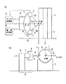
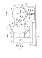
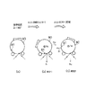
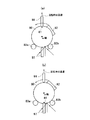
図1及び図2は、本発明の第1の実施の形態を示す図である。本実施の形態は、簡略化された実施の形態であり、予め略円筒状結晶であるワークの結晶面法線の側面周方向の方位が分っている場合に適用できるものである。まず、図1を用いて本実施の形態の構成を説明する。円筒形の結晶インゴットであるワーク(被検体)1が、ワーク軸であるω軸の周りに手動で回転可能に保持手段としての保持台9で支えられている。測定部12は、X線管3によりワーク1側面のC点に水平方向からX線ビーム6aを照射し、その回折されたX線ビーム6bをX線検出器5で測定する。X線管3とX線検出器5はδフレーム7上でC点を中心に角度2αをもって配置されており、X線管3には線源コリメータ4が付いている。αはブラッグ角θ0 に対しα=90゜−θ0 で計算される角度である。δフレーム7は水平面内でδ駆動部8によりδ回転される。δ駆動部8は機構制御部10で制御される。データ処理部11はX線検出器5とδ駆動部8に接続され、検出器出力とδ値を受け取り、検出器出力ピーク時のδ値を取り込む。
【0023】
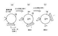
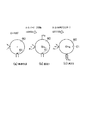
次に、図2を用いて、本実施の形態の作用を説明する。ワーク1は側面周囲にOF面2があり、周方向の結晶面法線の方位がOF面2に合っているがω軸に沿った方向の傾斜が不明なものである。まず、図2(a)に示すように、ω回転角Ω=180゜のOF面2水平位置に設定し、法線h1 を測定する。測定はδ回転を行い検出器出力ピーク時のδ値より測定基準z軸からx軸方向へのh1 の傾斜角δ0 (1) が求まる。次に、図2(b)に示すように、ω回転角Ω=270゜のOF面2垂直位置に設定し、法線h2 を測定する。同様にh2 の傾斜角δ0 (2) が求まる。求める法線h0 は所定の法線h0 ,h1 ,h2 が互いに直交する関係を用いて計算される。h0 のワーク座標ZからのX,Y方向への傾斜角δ0 (0) ,δ90 (0) は図から明らかなように、それぞれδ0 (0) =δ0 (1) ,δ90 (0) =δ0 (2) で求められる。本実施の形態は、各傾斜角が大きい場合、結果に誤差が生じる。
【0024】
上述した第1の実施の形態によれば、側面からの測定でワーク軸方向の結晶面法線を求めることができる。また側面に直交する方向の結晶面法線(再測定)とワーク軸方向の結晶面法線を1つの装置で求めることができる。
【0025】
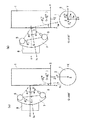
図3及び図4には、本発明の第2の実施の形態を示す。本実施の形態は、簡略化された実施の形態であるが、予め略円筒状結晶であるワーク1の結晶面法線の側面周方向の方位が分っていない場合にも適用できるものである。上述の第1の実施の形態との構成上の違いはφ駆動部13が追加された点である。φ駆動部13はδフレーム7とδ駆動部8をC点を原点とするz軸(=φ軸)の周りに回転させる。φ回転位置0゜でδ回転面が水平、90゜で垂直になる。
【0026】
次に、図4を用いて、本実施の形態の作用を説明する。まず、φ回転を90゜に設定し、手動でワーク1をω回転させて検出器出力が概略ピークとなる位置に設定する。この姿勢でワーク座標XYZが図3のように設定される。ここで第1の実施の形態と同様にφ回転0゜及び90゜でそれぞれx軸方向、y軸方向へのh1 の傾斜角δ0 (1) ,δ90 (1) を求める。次にワーク1を約90゜CW方向へω回転させ、この位置で同様にφ回転0゜でx軸方向へのh2 の傾斜角δ0 (2) を求める。図4の作図から分るように、δ0 (1) ,δ90 (1) ,δ0 (2) よりh0 の傾斜角、δ0 (0) ,δ90 (0) が求められる。
【0027】
上述した第2の実施の形態によれば、側面からの測定でワーク軸方向の結晶面法線を求めることができる。また側面に直交する方向の結晶面法線とワーク軸方向の結晶面法線を1つの装置で求めることができる。
【0028】
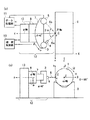
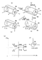
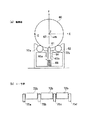
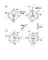
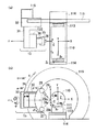
図5乃至図10には、本発明の第3の実施の形態を示す。まず、図5を用いて機構部の構成を説明する。同図(a)は同図(b)のA−A線断面図、同図(b)は同図(a)の右側面図である。プレート17が接着された円筒形の結晶インゴットであるワーク16が被検体である。ワーク16は保持手段としての載置台18にプレート17を係合させて取付けられる。載置台18はZフレーム23で支持され、略ワーク16の軸であるω軸に対しω駆動部19によりω回転される。Zフレーム23はZ駆動部24によりZ(ω軸)方向に駆動され測定点Cの位置が変更できる。測定部15は、X線管25によりワーク16側面のC点にX線ビーム26aを照射し、その回折されたX線ビーム26bをX線検出器27で測定する。X線管25とX線検出器27はδフレーム36上でC点を中心に角度2αをもって配置されている。δフレーム36はC点を中心にδ駆動部30によりδ回転される。φ駆動部31はδフレーム36とδ駆動部30をC点を原点とするz軸(=φ軸)の周りに回転させる。φ回転位置0゜でδ回転面が水平、90゜で垂直になる。φ駆動部31はz駆動部32によりz方向に駆動されC点をワーク16の側面に合わせる。測定部15は、測定座標xyzを基準に動き、この座標xyzで結晶面法線を求める。ワーク16に固定されたワーク座標XYZはプレート17を基準に設定され、図示されているω回転基準位置(Ω=180゜)のとき測定座標と方向が一致するように設定されている。ワーク16のω回転角は後述する極座標ωと区別するため大文字Ωで表し、X軸がz軸方向を向いたときΩ=0゜としCW方向を+にとる。X線管25は管電圧40kVの銅をターゲットとするもので、約8keVの銅の特性X線Kαを使用する。X線検出器27はガスを用いた比例計数管であり、X線のフォトンカウントを行うものである。
【0029】
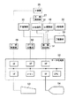
図6は、システム構成を示している。δ駆動部30、φ駆動部31、ω駆動部19、z駆動部32、Z駆動部24等の各機構部は、機構制御部51を介してデータ処理部52に接続されている。機構制御部51はデータ処理部52からの駆動タイミングや駆動量の指令を受け、それに従って各機構部を制御するとともに各機構部のステータス情報をデータ処理部52に送る。X線管25はX線制御部49を介してデータ処理部52に接続されている。X線制御部49はX線管25に電力を供給するとともに管電圧、管電流の制御及びデータ処理部52からの指令でX線管25のON・OFFを制御する。X線検出器27はデータ収集部50を介してデータ処理部52に接続されている。データ収集部50はデータ処理部52からの測定開始信号によりX線検出器27の出力パルスをカウントしてデジタルデータとしてデータ処理部52に送る。データ処理部52は通常のパソコンであり、マンマシンインタフェースとしてのキーボード53と表示器54とが接続されている。ここで、メニュー、ステータス、結果等の表示や、メニュー選択、測定開始、測定中断などの操作者による入力が行われる。データ処理部52は記憶されているシーケンスに従って各部を制御し測定を行い、記憶されている計算プログラムに従って結果を計算する。
【0030】
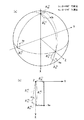
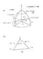
次に、図7を用いて、本実施の形態の作用を説明する。この場合、測定する結晶面法線h1 ,h2 と求める結晶面法線h0 は互いに直交する関係にある。操作者はワーク16を設定し、測定開始を入力するとデータ処理部52は以下のように測定及びh0 の計算を行い表示する。まず測定部15をφ=90゜,δ=0゜に設定しワーク16を基準位置(Ω=180゜)からCCW方向に回転させながら検出器出力のピークを探し、概略ピーク位置で回転を止める(ωサーチと称する)。このときの回転量をΔΩ1 (負値)とする。この位置で測定部15により結晶面法線h1 を測定する。φ=0゜及び90゜それぞれでδ回転スキャンを行い、それぞれh1 のz軸からのx方向、y方向の傾斜角δ0 (1) ,δ90 (1) を求める。次にワーク16をさらにΔΩ2 (略−90゜)回転させ、同様に結晶面法線h2 を測定しδ0 (2) ,δ90 (2) を求める。ΔΩ2 は法線hが測定部15の測定範囲に入る程度の停止精度で回転させればよいが回転量は正確にデータ処理部52に取り込まれる。測定した結晶面法線h1 ,h2 より下記計算▲1▼でh0 を計算する。
【0031】
<計算▲1▼:h1 ,h2 からh0 を計算(ΔΩ既知、ワーク座標補正なし)>;平行しない2つのベクトルh1 ,h2 から両者に直交する単位ベクトルh0 を算出することができる。計算式はベクトル表示で次式となる。
【0032】
【数1】
h0 =±(h1 ×h2 )/√{1−(h1 ・h2 )^2} …(2)
ここで×はベクトル積、・は内積を示す。具体的には、まずh1 ,h2 をそれぞれ次式で直交座標に変換する。
【0033】
【数2】
x=cos δ90・tan δ0 ・√{1/(1+ cos2 δ90・ tan2 δ0 )}…(3)
y=cos δ0 ・tan δ90・√{1/(1+ cos2 δ0 ・ tan2 δ90)}…(4)
z=√(1−x^2−y^2) …(5)
この式にδ0 (1) ,δ90 (1) を代入してx1 ,y1 ,z1 を求め、δ0 (2) ,δ90 (2) を代入してx2 ,y2 ,z2 を求める。
【0034】
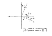
次いで、図8を参照して、h1 ,h2 をそれぞれ測定時のワーク座標へ変換する。変換式、
【数3】
【数4】
【0035】
δ0 =arctan(X/Z) …(8)
δ90=arctan(Y/Z) …(9)
この式のX,Y,ZにX0 ,Y0 ,Z0 を代入してδ0 (0) ,δ90 (0) を得る。ここで代りにZ軸に対する最大傾斜δとその方位φを求めることもできる。計算は、
【数5】
【0036】
計算▲1▼でワーク座標と測定座標がずれている場合、補正をすることができる(計算▲2▼)。
【0037】
<計算▲2▼:h1 ,h2 からh0 を計算(ΔΩ既知、ワーク座標補正あり)>;h1 ,h2 をそれぞれ式(3),(4),(5)で直交座標変換し、x1 ,y1 ,z1 ,x2 ,y2 ,z2 を求める。基準位置Ω=180゜におけるワーク座標と測定座標の角度関係を予め測定しておき変換係数(Xx 〜Zz )がインプットされているものとすれば、これをワーク座標に変換できる。図9に座標の関係を示す。まず、h1 ,h2 をそれぞれ測定座標xyzから基準位置でのワーク座標Xs Ys Zs へ変換し、次に測定時のワーク座標XYZに変換する。Xs Ys Zs 座標への変換式、
【数6】
【数7】
【数8】
【0038】
計算▲2▼で用いる測定座標からワーク座標への変換係数(Xx 〜Zz )は機械的な測定で求めることもできるが本実施の形態では、自動的にも求めることができる。操作者は較正用ワークを載置台18に載置し、座標較正モードを選択して測定開始させ、表示に従って反転載置に替え、測定をさらに行うとデータ処理部52は以下のように各測定を行い変換係数を計算して記憶する。
【0039】
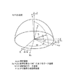
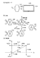
図10を参照して座標較正モードでの作用を説明する。較正には同図に示すような結晶面法線の概略方向に平行にプレート56を接着した較正用ワーク55を用いる。平行度は法線が測定の範囲に入る程度でよい。基準位置Ω=180゜でのワーク座標Xs Ys Zs が測定対象である。基準位置でφ=0゜及び90゜それぞれでδ回転スキャンを行い法線h1 (O)を求める。次に操作者によるY反転(載置替え)とω回転によるZ反転を同時に行ってX反転させる。ここで法線h1 (X)を求める。次にh1 (O)とh1 (X)の中点がXs 軸であることを利用して測定座標でXs 軸が計算できる。またY反転、Z反転で法線h3 (Y),h3 (Z)もそれぞれ求め、4点を平均してXs 軸を求めてもよい(h3 はh1 の反対向き法線)。この場合、統計精度を上げることができる。ワーク座標を確定させるには、さらにXs 軸に対する回転自由度を固定させる必要があるが、これは機械測定によるZs 軸のzx平面となす角gzを用いる。Xs 軸と比べgzの精度は低くてよい。これにより、変換係数が計算される(計算▲3▼)。なお、この座標較正は頻繁に行う必要はない。
【0040】
<計算▲3▼:座標変換係数の計算>;測定座標xyzと基準位置でのワーク座標Xs Ys Zs との変換係数を求める。測定値を、
基準位置 h1 (O):δ0 (O),δ90(O)
X反転 h1 (X):δ0 (X),δ90(X)
Y反転 h3 (Y):δ0 (Y),δ90(Y)
Z反転 h3 (Z):δ0 (Z),δ90(Z)
機械測定 Zs 軸のzx平面となす角:gz
とする。中点を求めるため、それぞれ式(3),(4),(5)で直交座標変換し、h1 (O)とh1 (X)の2点平均あるいはh1 (O),h1 (X),h3 (Y),h3 (Z)の4点平均で3次元的中点xc ,yc ,zc を求める。中点と逆方向の単位ベクトルが基準位置でのXs 軸になるのでXs 軸のx,y,z成分は(sは省略して)、
r=√(xc 2 +yc 2 +zc 2 ) …(15)
Xx =−xc /r …(16)
Xy =−yc /r …(17)
Xz =−zc /r …(18)
で求まる。次にZs 軸を求める。Zs 軸とzx平面の角度gz(上向き+)は既知として、Zs 軸のy成分は
Zy = sin(gz) …(19)
となる。未知数Zx ,Zz はXs 軸とZs の内積が0であることと、|Zs |=1の2つの式を条件Zx >0で解いて求められる。解は、
【数9】
Yx =Zy ・Xz −Zz ・Xy …(22)
Yy =Zz ・Xx −Zx ・Xz …(23)
Yz =Zx ・Xy −Zy ・Xx …(24)
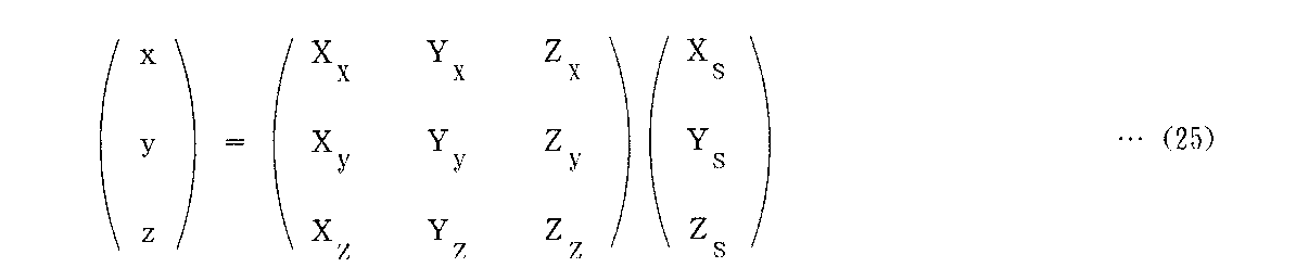
で計算される。求めたXx ないしZz を使って基準位置でのワーク座標Xs Ys Zs から測定座標xyzへの変換は、
【数10】
【0041】
上述した第3の実施の形態によれば、ワーク16の側面からの測定でワーク軸方向の結晶面法線を求めることができる。側面に直交する方向の結晶面法線とワーク軸方向の結晶面法線を1つの装置で求めることができる。ワーク16のプレート17を基準としたワーク座標で結晶面法線を求めることができる。またワーク座標と測定座標のずれを補正するので正確に結晶面法線を求めることができ、ずれの較正も自動的に行うことができる。
【0042】
次に、第3の実施の形態の各変形例を述べる。上述した第3の実施の形態でワーク軸方向の結晶面法線だけでなく、側面に直交する方向の結晶面法線が測定されるので、これを基に結晶面法線の周方向の方位を示すノッチ(v溝)あるいはOF面を加工することもできる。
【0043】
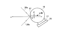
図11には、第3の実施の形態の第1の変形例を示す。この変形例は、測定座標のz軸がω軸から距離dだけ離れるよう、測定部が変位して配置されている。ワーク16の側面に結晶面法線の周方向の方位を示すノッチ(v溝)57が既に加工されているワーク16の場合、このノッチ57とC点が干渉して正常な測定ができない場合がある。少なくともdをノッチ57の幅の1/2以上とって配置することで、この干渉を防ぐことができ、ノッチ57のある場合でも正確な測定が可能となる。
【0044】
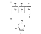
図12には、第3の実施の形態の第2の変形例を示す。この変形例では、複数のワーク(結晶インゴット)58a,58b,58cがそれぞれサブプレート71a,71b,71cを介してプレート59に接着されている。マルチワイアソーによるスライシングマシンにかけて全スライス同時切断する前のワークであり、各ワーク58a,58b,58cはそれぞれ略軸方向の結晶面法線h0 がプレート59に合うように接着されている。本実施の形態の装置では、スライシングマシンにかける前の接着ずれ有無の最終確認を行う。接着ずれがあるとそのワーク分全てが不良になってしまう。従来装置では中間に挟まったワーク58bは軸方向法線h0 を測定することができなかったが、この変形例により全てのワーク58a,58b,58cそれぞれについて測定することが可能になる。
【0045】
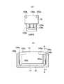
図13には、第3の実施の形態の第3の変形例を示す。第3の実施の形態では、プレート基準でω回転基準位置を設定したが、この変形例はノッチ基準で設定するものである。ガイド101a,101bとスプリング102a,102bで上下方向にスライドする係合板100a,100bを上下2箇所に設け、ノッチ57を上側あるいは下側に位置決めする。上下の係合板100a,100bは、プレート17を下にしたときノッチ57が右側にあるか左側にあるかで使い分ける。またω回転するときは係合板100a,100bは干渉しないように退避させる。
【0046】
図14には、第3の実施の形態の第4の変形例を示す。上記の係合板100a,100bは、図14に示すように、左右2箇所に設けてもよい。同図では、ガイドとスプリングは省略されている。この場合、左右の係合板100a,100bはプレート17を下にしたとき、ノッチ57が上側にあるか下側にああるかで使い分け、上記と同様にω回転時には退避する。上記の第3、第4の変形例において、係合板100a,100bの代りに機械式あるいは光学式センサを用いてもよい。
【0047】
第3の実施の形態の第5の変形例を説明する。OF面をもつワークに対し、水準器等の傾斜計でOF面の傾斜度を測ってOF面基準でω回転基準位置を設定することもできる。
【0048】
上述の第3〜第5の変形例では、ΔΩ1 =0゜としてノッチやOF面を回転の基準とする。またここでΔΩ2 の正確な値が未知であっても、後述する第4の実施の形態における計算▲4▼を用いてh0 を計算することができるので第3〜第5の変形例では正確なω回転量を全く知ることなくh0 を求めることができる。
【0049】
図15には、第3の実施の形態の第6の変形例を示す。第3の実施の形態ではプレート17が接着されたワーク16を載置台18にネジで固定するが、この第6の変形例では、さらにスプリング105で加勢されたロッド103でワーク16を載置台18に押し付ける。これにより回転時に接着部にかかる力を緩和させることができる。これは特に大きなワーク16の場合に有効である。
【0050】
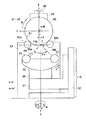
図16乃至図20には、本発明の第4の実施の形態を示す。まず、図16を用いて機構部の構成を説明する。円筒形の結晶インゴットであるワーク60がワーク軸であるω軸の周りに手動で回転可能に保持板63a,63bを介して保持台62で支えられている。2つの保持板63a,63bは垂直な中心平面67に対し互いに鏡像の形をなしており、摩擦の少ないテフロン等が用いられている。この2つの保持板63a,63bの中間にはノッチ(v溝)61に係合する係合板64が中心平面67上に配置され、中心平面67に沿って動くようにガイド65a,65bで保持されている。係合板64はスプリング66により加勢されノッチ61に係合される。これによりワーク60の中心軸であるω軸とノッチ61が常に中心平面67の上になるように位置決めされる。ワーク60の側面側に測定部15が設置され、側面のC点にX線ビーム26aを照射し結晶面法線を測定する。測定部15は、前記第3の実施の形態と同じものである。第3の実施の形態の場合と同様に、測定部15は、測定座標xyzを基準に動き、この座標xyzで結晶面法線を求める。ワーク60に固定されたワーク座標XYZはワーク60の側面から決まる中心軸(ω軸)を基準に設定され、図示されているノッチ61が係合した位置であるω回転基準位置(Ω=180゜)のとき測定座標と方向が一致するように設定されている。ワーク60のω回転角は後述する極座標ωと区別するため大文字Ωで表し、X軸がz軸方向を向いたときΩ=0゜としてCW方向を+にとる。機構部以外の構成部分は、前記第3の実施の形態と略同様である。
【0051】
次に、図17を用いて、本実施の形態の作用を説明する。この場合、測定する結晶面法線h1 ,h2 と求める結晶面法線h0 は互いに直交する関係にある。操作者は、まずワーク60をノッチ61が係合した基準位置(Ω=180゜)に設定し、測定開始を入力するとデータ処理部52は、この位置、ΔΩ1 (=0゜)で測定部15により結晶面法線h1 を測定する。φ=0゜及び90゜それぞれでδ回転スキャンを行い、それぞれh1 のz軸からのx方向、y方向の傾斜角δ0 (1) ,δ90 (1) を求める。次にワーク60の回転の指示を表示する。操作者は、ワーク60をΔΩ2 (略−90゜)回転させる。ΔΩ2 は既知の値とする。操作者がΔΩ2 と測定再開を入力すると、データ処理部52は同様に結晶面法線h2 を測定しδ0 (2) ,δ90 (2) を求める。さらに測定したh1 ,h2 よりh0 を計算する。計算は第3の実施の形態と同様に、前記計算▲1▼で行われる。またワーク座標と測定座標がずれている場合、同様に前記計算▲2▼を用いて補正をすることができる。計算▲2▼で用いる測定座標からワーク座標への変換係数(Xx 〜Zz )は、機械的な測定で求めることもできるが、第3の実施の形態と同様に自動的に求めることができる。図18を参照して、操作者は中心軸に対向して付けられた2つのノッチ69a,69bをもつ較正用ワーク68を載置台62に載置し、座標較正モードを選択して測定開始させ、表示に従って反転載置に替え、測定をさらに行うとデータ処理部52は各測定を行い変換係数を計算して記憶する。反転は、前記図10と同様である。変換係数の計算は前記計算▲3▼で行われる。図18に示すように、2つのノッチ69a,69bが対向位置よりεだけずれている場合、X反転、Z反転時の測定法線h1 (X),h3 (Z)は反対方向にεだけずれる。したがって、このノッチ69a,69bのずれεがあっても4点、h1 (O),h1 (X),h3 (Y),h3 (Z)を平均することで正確にXs 軸を求めることができる。このように4点平均が好ましいが、ノッチ69a,69bのずれがない場合は、h1 (O)とh1 (X)の2点平均でよい。
【0052】
前記の計算▲1▼あるいは計算▲2▼は回転量ΔΩ2 が既知の場合であるが、ΔΩ2 の正確な値が未知であってもh0 を計算することができる。ΔΩ2 は法線hが測定部15の測定範囲に入る程度の停止精度で回転させればよく未知でもよい。この場合、法線h2 の方位が定まらないが、所定の法線h1 ,h2 間の角度R12(いまの場合90゜)が既知であることを利用してh2 を確定し、これにより法線h0 を求める。ΔΩ2 が未知の場合、前記の計算▲1▼あるいは計算▲2▼の代りに下記の計算▲4▼を用いる。なお計算▲4▼は第3の実施の形態に対しても適用することができる。またh1 とh2 はどちらを先に測定してもよい。
【0053】
<計算▲4▼:h1 ,h2 からh0 を計算(ΔΩ2 未知、ワーク座標補正あり)>;まず、h1 ,h2 をそれぞれ式(3),(4),(5)で直交座標変換し、x1 ,y1 ,z1 ,x2 ,y2 ,z2 を求める。基準位置Ω=180゜におけるワーク座標と測定座標の角度関係を予め測定しておき変換係数(Xx 〜Zz )がインプットされているものとすれば、これをワーク座標に変換できる。図19に座標の関係を示す。まず、h1 について測定座標xyzから基準位置でのワーク座標Xs Ys Zs へ変換し、次に測定時のワーク座標XYZ(極座標γ,ω)に変換する。前出の変換式(12),(13)でXs1,Ys1,Zs1,X1 ,Y1 ,Z1 を求める。ここでΔΩ=ΔΩ1 を用いる。次に、X1 ,Y1 ,Z1 を次式の極座標変換に代入し極座標表現γ1 ,ω1 に変換する。
【0054】
【数11】
γ=γs …(28)
ω=ωs +ΔΩ …(29)
でΔΩ=ΔΩ1 を用いて求めてもよい。またX1 ,Y1 ,Z1 は逆にγ1 ,ω1 から次式の直交座標変換で求めてもよい。
【0055】
X=cos γ・cos ω …(30)
Y=cos γ・sin ω …(31)
Z=sin γ …(32)
次にh2 について前記の式(12)でxyz座標からXs Ys Zs 座標へ変換し、Xs2,Ys2,Zs2を求める。そしてXs2,Ys2,Zs2を上式(26),(27)で極座標表現γs2,ωs2に変換する。
【0056】
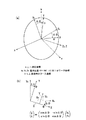
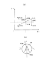
次に、図20に測定時のワーク座標XYZを固定した図、即ちワークに乗ってh1 ,h2 を見た図を示す。この図を参照して、γs2,ωs2を測定時のワーク座標(極座標表現)γ2 ,ω2 に変換するが、ΔΩ2 が未知であるので、ω2 がそのままでは求められない。しかしながら、h1 ,h2 間の角度R12が既知であるので、これを利用してω2 を求めることができる。図20(b)の三角形Zh1 h2 に球面三角法を適用して、
【数12】
Cw =SIGN(sin (ΔΩ2 )):ΔΩ2 は概略値 …(33)
γ2 =γs2 …(34)
ω2 =ω1 +Cw ・arccos{(cos R12−sin γ1 ・sin γ2 )/(cos γ1 ・cos γ2 )} …(35)
でγ2 ,ω2 が求められる。ここでCw はsin ΔΩ2 の符号で+1あるいは−1のどちらかであり、この計算で用いるΔΩ2 は概略値である。即ちΔΩ2 は未知ではあるが+90゜側か、−90゜側かの程度では知られているものとする。次にγ2 ,ω2 を式(30),(31),(32)で直交座標変換し、X2 ,Y2 ,Z2 を求める。
【0057】
次に、h1 ,h2 から両者に直交する単位ベクトルh0 を、前記式(7)と同様に、
【数13】
【0058】
上述した第4の実施の形態によれば、ワーク60の側面からの測定でワーク軸方向の結晶面法線を求めることができる。側面に直交する方向の結晶面法線とワーク軸方向の結晶面法線を1つの装置で求めることができる。ワーク60の側面から決まる中心軸(ω軸)及びノッチを基準としたワーク座標で結晶面法線を求めることができる。ワーク座標と測定座標のずれを補正するので正確に結晶面法線を求めることができ、ずれの較正も較正用ワーク68を反転載置して測定することで自動的に行うことができる。またワーク60の正確な回転角が未知であっても正確に結晶面法線が測定できる。
【0059】
次に、第4の実施の形態の各変形例を述べる。上述した第4の実施の形態で係合板64を用いる代りに機械式あるいは光学式センサを用いてノッチ61の位置決めを行ってもよい。
【0060】
図21には、第4の実施の形態の第1の変形例を示す。この変形例は、保持板63a,63bの代りに2つのローラ72a,72b用いてワーク60を支えるようにしたものである。これによりスムーズに回転できる。各ローラ72a,72bは図21(b)に示すように、両端部だけでなく中間部も軸受け75a〜75dで支えられている。これにより、たわみが少なくなり正確にワーク60を位置決めできる。ω回転は手動でなくローラ72a,72bをモータで回転させて行ってもよい。
【0061】
図22には、第4の実施の形態の第2の変形例を示す。この変形例は、保持板63a,63bの代りに2つの軸73a,73bと2つの軸受け74a,74bでワーク60の両端を支えるようにしたものである。ワーク60は軸73a,73bを介して両側から軸受け74a,74bで挟まれることで保持される。あるいはワーク60は軸73a,73bに接着されることで保持される。
【0062】
図23には、第4の実施の形態の第3の変形例を示す。この変形例は、OF面77をもつワークの場合である。この場合、OF面77を用いて基準位置の位置合わせを行う。これには例えば傾斜計78等を用いてOF面77を水平あるいは垂直に合わせることができる。またω回転の回転角もこの傾斜計78で測定できる。
【0063】
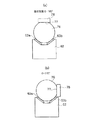
図24乃至図26には、本発明の第5の実施の形態を示す。本実施の形態は、プレート付きワークを側面で支えるようにしたものである。まず、図24を用いて機構部の構成を説明する。円筒形の結晶インゴットであるワーク80がワーク軸であるω軸の周りに手動で回転可能に2つのローラ83a,83bを介して保持台84で支えられている。2つのローラ83a,83bは水平面内で互いに平行に配置されている。ワーク80はプレート82が接着されているもので、ω軸回転はプレート82がローラ83a,83bに干渉しない180゜を少し超える範囲で可能である。プレート82の傾斜は傾斜計85で測定できる。ワーク80はノッチ81があるものでもOF面のあるものでも何もないものでも対応可能である。ワーク80の下面側に測定部15が設置され、ワーク80の下面のC点にX線ビーム26aを照射し結晶面法線を測定する。測定部15は、前記第3の実施の形態と同じものである。第3の実施の形態の場合と同様に、測定部15は、測定座標xyzを基準に動き、この座標xyzで結晶面法線を求める。ワーク80に固定されたワーク座標XYZはワーク80の側面から決まる中心軸(ω軸)を基準に設定され、図示されているプレート82が水平になる位置であるω回転基準位置(Ω=180゜)のとき測定座標と方向が一致するように設定されている。ワーク80のω回転角はΩで表し、X軸がz軸方向を向いたときΩ=0゜としてCW方向を+にとる。測定部15は測定座標のz軸がω軸から距離dだけ離れるよう、変位して配置されており、ノッチ81とC点の干渉を防ぐようになっている。機構部以外の構成部分は、前記第3の実施の形態と略同様である。
【0064】
次に、図25を用いて、本実施の形態の作用を説明する。この場合、測定する結晶面法線h1 ,h2 と求める結晶面法線h0 は互いに直交する関係にある。操作者は、まずワーク80を傾斜計85を用いて基準位置(Ω=180゜)からΔΩ1 (CCW−)回転してノッチ81が下方になるように設定し、ΔΩ1 値と測定開始を入力する。ノッチやOF面の無いワークの場合は手動で回転させながらX線検出器出力ピークを探し(ωサーチ)固定してからΔΩ1 値と測定開始を入力する。データ処理部52は、この位置で、前記第4の実施の形態と同様に、測定部15により結晶面法線h1 を測定し、δ0 (1) ,δ90 (1) を求め、次にワーク80の回転の指示を表示する。操作者がワーク80をΔΩ2 (略±90゜)回転させ、ΔΩ2 と測定再開を入力すると、データ処理部52は同様に結晶面法線h2 を測定しδ0 (2) ,δ90 (2) を求める。さらに測定したh1 ,h2 よりh0 を計算する。計算は第4の実施の形態と同様に、ΔΩ2 は未知でもよく、前記計算▲1▼、計算▲2▼又は計算▲4▼を用いて行われる。計算▲2▼又は計算▲4▼で用いる測定座標からワーク座標への変換係数(Xx 〜Zz )は、機械的な測定で求めることもできるが、第4の実施の形態と同様に自動的に求めることができる。これには図26に示すような結晶面法線の概略方向に平行にプレート88を接着した較正用ワーク87を用いる。平行度は法線が測定の範囲に入る程度でよい。図26を参照して、操作者はプレート88面が垂直になるように各反転を行いそれぞれ測定を行う。データ処理部52は第4の実施の形態同様、前述した計算▲3▼により変換係数を計算して記憶する。
【0065】
上述した第5の実施の形態によれば、ワーク80の側面からの測定でワーク軸方向の結晶面法線を求めることができる。側面に直交する方向の結晶面法線とワーク軸方向の結晶面法線を1つの装置で求めることができる。ワーク80の側面から決まる中心軸(ω軸)及びワーク80に取り付けられたプレート82を基準としたワーク座標で結晶面法線を求めることができる。ワーク座標と測定座標のずれを補正するので正確に結晶面法線を求めることができ、ずれの較正も較正用ワーク87を反転載置して測定することで自動的に行うことができる。ワーク80の正確な回転角が未知であっても正確に結晶面法線が測定できる。また、ノッチに邪魔されずに正確な測定が可能となる。
【0066】
次に、第5の実施の形態の各変形例を述べる。上述した第5の実施の形態でOF面の付いたワークの場合、プレート82の傾斜を測って基準とする代りにOF面の傾斜を測定してもよい。この場合、ワーク80の側面から決まる中心軸(ω軸)及びワーク80に付けられたOF面を基準としたワーク座標で結晶面法線を求めることができる。ω回転は手動ではなくローラ83a,83bをモータで回転させて行ってもよい。
【0067】
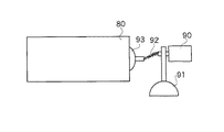
図27には、第5の実施の形態の第1の変形例を示す。この変形例は、ω回転角を測定するのに傾斜計85の代りにエンコーダ90を用いるものである。ワーク80の端面の略中央に吸盤あるいは粘着テープ等で取り付けた接合板93の回転をフレキシブルなジョイント92で固定台91上のエンコーダ90に伝達して回転量を測定する。またローラ83a,83bの軸にエンコーダを取り付けてもよく、エンコーダ専用ローラを介してエンコーダを取り付けてもよい。
【0068】
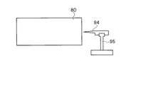
図28には、第5の実施の形態の第2の変形例を示す。この変形例は、ワーク80の端面にマークを付けるケガキ針やペン等のマーカ94とそれを水平方向あるいは垂直方向にスライドするスライド機構95を追加したものである。これにより基準位置や測定時の回転位置のマーク即ち測定の基準を直接ワーク80に付けることができる。
【0069】
図29には、第5の実施の形態の第3の変形例を示す。第5の実施の形態はプレート82を基準としてω回転基準位置を設定したが、この変形例はノッチ81を基準とするものである。下方の係合板97と上方の係合板98が追加されている。各係合板97,98の保持は省略されているが、図16の第4の実施の形態と同様である。各係合板97,98は、ω軸に対して対称に位置する。この変形例ではノッチ81がどちらかの係合板に係合した状態をω回転基準位置とするが、ノッチ81がプレート82に近いときは上方の係合板98を用い、遠いときには下方の係合板97を用いる。上方の係合板98は回転時にはプレート82に干渉しないように退避させる。これにより、ワーク80の側面から決まる中心軸(ω軸)及びワーク80に付けられたノッチ81を基準としたワーク座標で結晶面法線を求めることができる。
【0070】
図30及び図31には、本発明の第6の実施の形態を示す。本実施の形態は、前記第3の実施の形態でω回転をワークではなく、測定部15で行うようにしたものである。プレート111が付いたワーク110は載置台112に固定され、Z駆動部114によりZ方向に移動されるのみで、ω回転は測定部15がωレール115上を動くことで行われる。測定部15の回転はCCW方向を+にとることで相対的にワーク回転をCW+で回転するのと全く同じになる。この構成によるワーク座標XYZはωレール115で決まるω軸を基準として設定される。このワーク座標XYZとは別のプレート111で決まるプレート座標Xp Yp Zp を設定し、結果はこの座標Xp Yp Zp で求める。ワーク座標XYZとプレート座標Xp Yp Zp は機械的に方向を合わせておく必要はない。測定部15は、測定座標xyzで測定を行う。測定座標xyzに乗ってみた場合のω回転基準位置におけるワーク座標とプレート座標をそれぞれXs Ys Zs ,XpsYpsZpsとし、測定時のワーク座標とプレート座標をそれぞれXYZ,Xp Yp Zp とする。
【0071】
次に、本実施の形態の作用を説明する。本実施の形態の作用は、ワーク110が回転する代りに測定部15が回転するだけで、前記第3の実施の形態と同様である。結果の結晶面法線h0 ,h1 ,h2 はプレート座標で求めるが計算は次の計算▲5▼で行う。
【0072】
<計算▲5▼:h1 ,h2 からh0 を計算(計算▲1▼▲2▼▲4▼のプレート座標変換付き)>;ワーク座標で求めた結晶面法線をさらに別の座標に変換して求めることができる。この別の座標をここではプレート座標と名付けるが必ずしもプレートに基づいた座標でなくてもよい。まず前記計算▲1▼▲2▼あるいは▲4▼を用いてh1 ,h2 ,h0 をワーク座標XYZで求め、次に変換
【数14】
【0073】
計算▲5▼で用いるプレート座標Xp Yp Zp への変換係数(Pij)及び測定座標から基準位置でのワーク座標Xs Ys Zs への変換係数(Xx 〜Zz )は、機械的な測定で求めることもできるが、本実施の形態では自動的に求めることができる。操作者は較正用ワークを載置台112に載置し、座標較正モードを選択して測定開始させ、表示に従って反転載置に替え、測定をさらに行うとデータ処理部は以下のように各測定を行い変換係数を計算して記憶する。
【0074】
図31を参照して座標較正モードでの作用を説明する。座標較正はxyz座標、Xs Ys Zs 座標及びXpsYpsZps座標間の変換係数を求める較正である。較正には図31(a)に示すような較正用ワーク120を用いる。較正用ワーク120は180゜は反転載置可能なプレート121を結晶面法線の概略方向に平行になるように接着したものである。平行度は法線が測定の範囲に入る程度でよい。図31(b)に反転を示す。ω回転基準位置における各軸の反転はワーク120の載置替えで行い、Z軸の反転は測定部15のω回転で行う。図31(c)に測定値の関係を示す。各位置での測定法線をh1 (O),h1 (Xp ),h3 (Yp ),h3 (Zp ),h3 (Z)とする(h3 はh1 の反対向き法線)。ここでh1 (O)とh1 (Xp )の中点がXps軸であることを利用して測定座標でXps軸が計算できる。またh1 (O),h1 (Xp ),h3 (Yp ),h3 (Zp )の4点を平均してXps軸を求めてもよい。次にh1 (O),h3 (Z)の中点をXs 軸として求める(定義)。各座標を確定させるには、さらにYps,Xs 軸に対する回転自由度を固定させる必要があるが、これは機械測定によるZps,Zs 軸のzx平面となす角それぞれgzp,gzを用いる。Xps,Xs 軸と比べgzp,gzの精度は低くてよい。これにより、変換係数が計算される(計算▲6▼)。なお、この座標較正は頻繁に行う必要はない。
【0075】
<計算▲6▼:座標変換係数の計算>;測定座標xyzと基準位置でのワーク座標Xs Ys Zs 、プレート座標XpsYpsZpsとの変換係数を求める。測定値を
【数15】
基準位置 h1 (O) :δ 0 (O),δ90(O)
Xp 反転 h1 (Xp ):δ0 (Xp ),δ90(Xp )
Yp 反転 h3 (Yp ):δ0 (Yp ),δ90(Yp )
Zp 反転 h3 (Zp ):δ0 (Zp ),δ90(Zp )
Z反転 h3 (Z) :δ0 (Z),δ90(Z)
機械測定 Zs 軸のzx平面となす角:gz
Zps軸のzx平面となす角:gzp
とする。まず、Xs Ys Zs 軸を求める。測定値をそれぞれ式(3),(4),(5)で直交座標変換し、h1 (O)とh3 (Z)の2点平均で3次元的中点xc ,yc ,zc を求める。計算▲3▼と同様に、式(15)〜(24)でXs Ys Zs 軸それぞれのxyz成分Xx ,Xy ,Xz ,Yx ,Yy ,Yz ,Zx ,Zy ,Zz が求められる。次に、XpsYpsZps軸を求める。同様に測定値を直交座標変換し、h1 (O)とh1 (Xp )2点平均あるいはh1 (O),h1 (Xp ),h3 (Yp ),h3 (Zp )の4点平均で3次元的中点xc ,yc ,zc を求め、式(15)〜(24)でXpsYpsZps軸それぞれのxyz成分Xpx,Xpy,Xpz,Ypx,Ypy,Ypz,Zpx,Zpy,Zpzが求められる。求めたXx ないしZz を使ってXs Ys Zs 座標からxyz座標への変換は前記変換式(25)のようになる。逆の変換は転置行列で計算でき、前記変換式(12)となる。また、XpxないしZpzを使ってXpsYpsZps座標からxyz座標への変換は、同様に
【数16】
【数17】
【数18】
【数19】
【数20】
【0076】
上述した第6の実施の形態によれば、ワーク110の側面からの測定でワーク軸方向の結晶面法線を求めることができる。側面に直交する方向の結晶面法線とワーク軸方向の結晶面法線を1つの装置で求めることができる。ワーク110のプレート111を基準としたプレート座標で結晶面法線を求めることができる。プレート座標と測定座標のずれを補正するので正確に結晶面法線を求めることができ、ずれの較正も自動的に行うことができる。プレート111がω回転軸とずれていてもプレート座標で結晶面法線を求めることができ、ずれの較正も自動的に行うことができる。また、ワーク110を回転させずに測定できる利点があり、寸法の大きなワークに適している。
【0077】
次に、第6の実施の形態の変形例を述べる。上述した第6の実施の形態でω回転をワーク110に行わせることもできる。これは、即ち第3の実施の形態でプレート17がワーク座標XYZとずれて設定されている場合である。この場合第6の実施の形態と同様の手順と計算をすることでプレートを基準とする座標Xp Yp Zp で結果を求めることができる。
【0078】
【発明の効果】
以上説明したように、請求項1記載の結晶方位測定装置によれば、略円筒状結晶である被検体を保持する保持手段と、前記被検体の側面の略1点に向けてX線ビームを放射し回折された回折X線を検出することで前記側面に略直交する結晶面法線の方向を測定する測定部と、前記被検体もしくは前記測定部を略前記被検体の軸であるω軸の周りにω回転させるω回転機構と、このω回転における第1及び第2の位置でそれぞれ測定した互いに非平行な第1及び第2の結晶面法線より前記ω軸に略平行な第3の結晶面法線を所定の数式を用いて求めるデータ処理部とを具備させたため、略円筒状結晶である被検体の側面からの測定のみで、略円筒軸方向の第3の結晶面法線を求めることができる。また、被検体の側面に直交する方向の結晶面法線と円筒軸方向の結晶面法線とを1つの装置で求めることができる。
【0079】
請求項2記載の結晶方位測定装置によれば、前記データ処理部は、前記第1及び第2の結晶面法線を前記測定部の測定基準である測定座標から前記被検体を基準とする被検体座標へ変換する機能を持つようにしたため、測定座標と被検体座標のずれが補正されて、被検体座標を基準とした第3の結晶面法線を精度よく求めることができる。
【0080】
請求項3記載の結晶方位測定装置によれば、前記データ処理部は、前記被検体座標の少なくとも1つの軸について前記被検体もしくは前記測定部が反転された時の、この反転の前後でそれぞれ測定した結晶面法線より前記測定座標と前記被検体座標との変換係数を求める機能を持つようにしたため、変換係数を自動的に計算することができる。
【0081】
請求項4記載の結晶方位測定装置によれば、前記データ処理部は、前記ω回転における第1の位置もしくは第2の位置が未知である場合、既知量である第1及び第2の結晶面法線間の角度を用いて前記第3の結晶面法線を求めるようにしたため、ω回転位置が未知であっても、第3の結晶面法線を精度よく求めることができる。
【0082】
請求項5記載の結晶方位測定装置によれば、周囲に被検体軸に沿った溝を持つ前記被検体について、前記測定部の測定基準である測定座標における略前記側面に直交する座標軸が前記ω軸に対し前記溝の幅の1/2以上の距離をもって交差するように前記測定部が前記ω軸に対し変位して配置されているようにしたため、周囲に結晶面法線の周方向の方位を示す溝が加工されている被検体についても溝に干渉されることなく、第3の結晶面法線を正確に求めることができる。
【0083】
請求項6記載の結晶方位測定装置によれば、前記被検体はプレートが取付けられた略円筒状結晶であり、前記保持手段は前記プレートを位置決めし前記被検体座標は前記プレートを基準に設定されるようにしたため、被検体に位置決め用のプレートが取り付けられているとき、このプレートを基準とした被検体座標で第3の結晶面法線を正確に求めることができる。
【0084】
請求項7記載の結晶方位測定装置によれば、前記保持手段は前記被検体の側面を位置決めし、前記被検体座標は前記被検体の側面を基準に設定されるようにしたため、被検体が、その側面で保持手段に位置決めされているとき、その被検体の側面を基準とした被検体座標で第3の結晶面法線を正確に求めることができる。
【0085】
請求項8記載の結晶方位測定装置によれば、周囲に被検体軸に沿ったマークを持つ前記被検体について、前記マークを基準に前記ω回転を位置決めするω位置決め手段を持ち、前記ω回転における第1及び第2の位置の何れか一方は前記マークを基準に設定されるようにしたため、周囲に結晶面法線の周方向の方位を示す溝等のマークを持つ被検体の場合、このマークをω回転の測定基準として第3の結晶面法線を容易に求めることができる。
【0086】
請求項9記載の結晶方位測定方法によれば、略円筒状結晶である被検体を保持する保持手段と、前記被検体の側面の略1点に向けてX線ビームを放射し回折された回折X線を検出することで前記側面に略直交する結晶面法線の方向を測定する測定部と、前記被検体もしくは前記測定部を略前記被検体の軸であるω軸の周りにω回転させるω回転機構とを用い、このω回転の第1及び第2の位置でそれぞれ測定した互いに非平行な第1及び第2の結晶面法線より前記ω軸に略平行な第3の結晶面法線を求めるようにしたため、略円筒状結晶である被検体の側面からの測定のみで、略円筒軸方向の第3の結晶面法線を計算により求めることができる。
請求項10記載の結晶方位測定方法によれば、前記第1及び第2の結晶面法線を前記測定部の測定基準である測定座標から前記被検体を基準とする被検体座標へ変換した上で第3の結晶面法線を求めるようにしたため、測定座標と被検体座標のずれが補正されて、被検体座標を基準とした第3の結晶面法線が精度良く求めることができる。
【0087】
請求項11記載の結晶方位測定方法によれば、前記被検体座標の少なくとも1つの軸について前記被検体もしくは前記測定部を反転し、この反転の前後でそれぞれ測定した結晶面法線より前記測定座標と前記被検体座標との変換係数を求めるようにしたため、変換係数を自動的に計算することができる。
【0088】
請求項12記載の結晶方位測定方法によれば、前記ω回転における第1の位置もしくは第2の位置が未知である場合、既知量である第1及び第2の結晶面法線間の角度を用いて前記第3の結晶面法線を求めるようにしたため、ω回転位置が未知であっても、第3の結晶面法線を精度よく求めることができる。
【図面の簡単な説明】
【図1】本発明の第1の実施の形態である結晶方位測定装置の構成図である。
【図2】上記第1の実施の形態の作用を説明するための図である。
【図3】本発明の第2の実施の形態の構成図である。
【図4】上記第2の実施の形態におけるh0 計算を説明するための図である。
【図5】本発明の第3の実施の形態における機構部の構成図である。
【図6】上記第3の実施の形態における制御系を示すブロック図である。
【図7】上記第3の実施の形態の作用を説明するための図である。
【図8】上記第3の実施の形態におけるh0 計算▲1▼を説明するための図である。
【図9】上記第3の実施の形態におけるh0 計算▲2▼を説明するための図である。
【図10】上記第3の実施の形態におけるワーク座標較正を説明するための図である。
【図11】上記第3の実施の形態の第1の変形例を説明するための図である。
【図12】上記第3の実施の形態の第2の変形例を説明するための図である。
【図13】上記第3の実施の形態の第3の変形例を説明するための図である。
【図14】上記第3の実施の形態の第4の変形例を説明するための図である。
【図15】上記第3の実施の形態の第6の変形例を説明するための図である。
【図16】本発明の第4の実施の形態における機構部の構成図である。
【図17】上記第4の実施の形態の作用を説明するための図である。
【図18】上記第4の実施の形態におけるワーク座標較正を説明するための図である。
【図19】上記第4の実施の形態におけるh0 計算▲4▼を説明するための図である。
【図20】上記第4の実施の形態におけるh0 計算▲4▼を説明するための他の図である。
【図21】上記第4の実施の形態の第1の変形例を説明するための図である。
【図22】上記第4の実施の形態の第2の変形例を説明するための図である。
【図23】上記第4の実施の形態の第3の変形例を説明するための図である。
【図24】本発明の第5の実施の形態における機構部の構成図である。
【図25】上記第5の実施の形態の作用を説明するための図である。
【図26】上記第5の実施の形態におけるワーク座標較正を説明するための図である。
【図27】上記第5の実施の形態の第1の変形例を説明するための図である。
【図28】上記第5の実施の形態の第2の変形例を説明するための図である。
【図29】上記第5の実施の形態の第3の変形例を説明するための図である。
【図30】本発明の第6の実施の形態における機構部の構成図である。
【図31】上記第6の実施の形態におけるワーク座標較正を説明するための図である。
【図32】X線回折を一般的に説明するための図である。
【図33】結晶方位測定装置の第1の従来技術の構成図である。
【図34】結晶方位測定装置の第2の従来技術の構成図である。
【符号の説明】
1,16,58,60,76,80,110 ワーク(被検体)
3,25 X線管
5,27 X線検出器
6a,26a X線ビーム
6b,26b 回折X線
9,62,84 保持台(保持手段)
11,52 データ処理部
12,15 測定部
17,56,59,82,88,111 プレート
18,112 載置台(保持手段)
19,116 ω駆動部
57,61,69,81 v溝[0001]
BACKGROUND OF THE INVENTION
The present invention relates to a crystal orientation measuring apparatus and a crystal orientation measuring method for measuring the crystal orientation of a single crystal sample such as silicon or quartz using X-ray diffraction.
[0002]
[Prior art]
In order to use a single crystal such as silicon or quartz as an industrial product such as a semiconductor or an oscillator, it is necessary to cut the surface so that it has a specific angle with respect to the crystal lattice plane. For this purpose, it is necessary to know the crystal lattice plane of the sample, but the most commonly used method for measuring the crystal lattice plane uses X-ray diffraction. FIG. 32 shows a method for measuring the lattice plane of a sample using this X-ray diffraction. That is, when an X-ray having a single wavelength is incident on the
[0003]
θ0= Arcsin (nλ / 2d) (1)
n; natural number of 1, 2, 3, ...
λ: X-ray wavelength (known)
d: Lattice spacing (known)
Thus, θ0Therefore, the crystal orientation can be measured by measuring the diffracted X-rays while changing the incident angle direction of the X-rays.
[0004]
Here, in the process of processing a cylindrical single crystal ingot into a disk (wafer) having a thickness of about 0.3 mm, crystal orientation measurement is usually performed in two steps. First, a single crystal ingot is ground into a cylindrical shape, the first crystal orientation is measured on the side surface (cylindrical surface), the orientation flat surface (OF surface) or V-groove along the axis is machined on the side surface, and the orientation mark and To do. Next, the end is cut at right angles to the cylindrical axis, and the second crystal orientation is measured for this sample section to determine the tilt angle between the defined crystal plane and the sample section, and parallel to the crystal plane or at a predetermined angle. The wafer is processed into a wafer with a slicing machine. The crystal orientation in the circumferential direction can be known from the peripheral OF surface of the wafer.
[0005]
An example of a crystal orientation measuring apparatus for measuring the crystal orientation of the first cylindrical surface is shown in FIG. 33 (Japanese Patent Laid-Open No. 62-116243). The
[0006]
As a crystal orientation measuring apparatus for measuring the crystal orientation of the second trial section, for example, there is a device as shown in FIG. 34 (Japanese Patent Laid-Open No. 2-31145). The
[0007]
The example of the crystal orientation measuring apparatus for the sample section is a type in which the inclination angle is directly adjusted integrally with the slicing machine, but only the inclination angle can be measured separately. The crystal orientation measurement of the first cylindrical surface and the crystal orientation measurement of the second sample cross section can be measured separately by changing the arrangement with the same apparatus.
[0008]
[Problems to be solved by the invention]
Conventionally, crystal orientation measurement for processing the OF surface of a single crystal ingot and crystal orientation measurement for slicing have been performed separately. Therefore, there is a problem that a separate device is required. In addition, even when using a single device, there is a problem that the measurement requires two measurements and the efficiency is low.
[0009]
The present invention has been made in view of the above, and it is possible to determine the orientation of a predetermined crystal plane whose normal is substantially in the direction of the cylindrical axis only by measurement from the side surface of the cylindrical crystal. It is an object of the present invention to provide a crystal orientation measuring apparatus and a crystal orientation measuring method capable of obtaining a crystal plane normal in a direction orthogonal to the side surface of a crystal and a crystal plane normal in a cylindrical axis direction with one apparatus.
[0010]
[Means for Solving the Problems]
In order to solve the above-mentioned problem, a crystal orientation measuring apparatus according to
h 0 = ± (h 1 × h 2 ) / √ {1- (h 1 ・ H 2 ) ^ 2}
(× indicates vector product, • indicates inner product)
Based on the formulaThe gist is to have a data processing unit to be obtained. With this configuration, the measurement unit measures the first and second crystal plane normals that are non-parallel to each other and whose normals are substantially orthogonal to the ω-axis, among the crystal planes of the subject. In the data processing unit, a third crystal plane normal which is substantially parallel to the ω axis and has a predetermined positional relationship with respect to the first and second crystal plane normals is obtained by calculation.
[0011]
The crystal orientation measuring apparatus according to
[0012]
The crystal orientation measuring device according to
[0013]
The crystal orientation measuring apparatus according to
[0014]
The crystal orientation measuring apparatus according to
[0015]
The crystal orientation measuring apparatus according to
[0016]
The crystal orientation measuring device according to
[0017]
The crystal orientation measuring device according to
[0018]
The crystal orientation measuring method according to
h 0 = ± (h 1 × h 2 ) / √ {1- (h 1 ・ H 2 ) ^ 2}
(× indicates vector product, • indicates inner product)
Based on the formulaThe gist is to seek. With this configuration, first and second crystal plane normals that are non-parallel to each other and whose normals are substantially orthogonal to the ω-axis are measured out of the crystal planes of the subject, and the first and second crystal plane methods are measured. A third crystal plane normal line substantially parallel to the ω axis and having a predetermined positional relationship with the line isBy calculationDesired.
The crystal orientation measurement method according to
[0019]
Claim11The crystal orientation measuring method described above is the claim10In the crystal orientation measurement method described above, the measurement coordinates and the object coordinates are obtained from crystal plane normals obtained by inverting the object or the measurement unit about at least one axis of the object coordinates and before and after the inversion. The gist is to obtain the conversion coefficient. With this configuration, the axis position of the subject coordinates is obtained by using the symmetry of the crystal plane normal measured before and after inversion with respect to the subject coordinates, and the conversion coefficient from the measured coordinates to the subject coordinates is obtained.
Conversion from measurement coordinates to object coordinates is performed using this conversion coefficient, and a third crystal plane normal is obtained with reference to the object coordinates.
[0020]
Claim12The crystal orientation measurement method according to
[0021]
DETAILED DESCRIPTION OF THE INVENTION
Hereinafter, embodiments of the present invention will be described with reference to the drawings.
[0022]
1 and 2 are diagrams showing a first embodiment of the present invention. This embodiment is a simplified embodiment, and can be applied to the case where the orientation in the side surface circumferential direction of the crystal plane normal line of a workpiece that is a substantially cylindrical crystal is known in advance. First, the configuration of the present embodiment will be described with reference to FIG. A workpiece (subject) 1 that is a cylindrical crystal ingot is supported by a holding table 9 as a holding means so as to be manually rotatable around a ω axis that is a workpiece axis. The
[0023]
Next, the effect | action of this Embodiment is demonstrated using FIG. The
[0024]
According to the first embodiment described above, the crystal plane normal in the workpiece axis direction can be obtained by measurement from the side surface. Further, the crystal plane normal (re-measurement) in the direction perpendicular to the side surface and the crystal plane normal in the workpiece axis direction can be obtained with one apparatus.
[0025]
3 and 4 show a second embodiment of the present invention. The present embodiment is a simplified embodiment, but can also be applied to a case where the orientation in the side surface circumferential direction of the crystal plane normal line of the
[0026]
Next, the effect | action of this Embodiment is demonstrated using FIG. First, the φ rotation is set to 90 °, and the
[0027]
According to the second embodiment described above, the crystal plane normal in the workpiece axis direction can be obtained by measurement from the side surface. Moreover, the crystal plane normal in the direction orthogonal to the side surface and the crystal plane normal in the workpiece axis direction can be obtained with one apparatus.
[0028]
5 to 10 show a third embodiment of the present invention. First, the structure of a mechanism part is demonstrated using FIG. 4A is a cross-sectional view taken along line AA in FIG. 2B, and FIG. 2B is a right side view of FIG. A
[0029]
FIG. 6 shows a system configuration. Each mechanism unit such as the
[0030]
Next, the effect | action of this Embodiment is demonstrated using FIG. In this case, the crystal plane normal h to be measured1, H2The crystal plane normal h to be obtained0Are orthogonal to each other. When the operator sets the
[0031]
<Calculation (1): h1, H2To h0(ΔΩ known, no workpiece coordinate correction)>; two non-parallel vectors h1, H2To the unit vector h orthogonal to both0Can be calculated. The calculation formula is expressed in vector form as follows.
[0032]
[Expression 1]
h0= ± (h1× h2) / √ {1- (h1・ H2) ^ 2} (2)
Here, x indicates a vector product, and • indicates an inner product. Specifically, first, h1, H2Are converted into Cartesian coordinates by the following equations.
[0033]
[Expression 2]
x = cos δ90・ Tan δ0・ √ {1 / (1 + cos2δ90・ Tan2δ0)} ... (3)
y = cos δ0・ Tan δ90・ √ {1 / (1 + cos2δ0・ Tan2δ90)} ... (4)
z = √ (1-x ^ 2-y ^ 2) (5)
In this equation, δ0 (1), Δ90 (1)X1, Y1, Z1And δ0 (2), Δ90 (2)X2, Y2, Z2Ask for.
[0034]
Next, referring to FIG.1, H2Is converted to the workpiece coordinates at the time of measurement. Conversion formula,
[Equation 3]
[Expression 4]
[0035]
δ0= Arctan (X / Z) (8)
δ90= Arctan (Y / Z) (9)
X, Y, Z in this formula0, Y0, Z0And δ0 (0), Δ90 (0)Get. Instead, the maximum inclination δ with respect to the Z axis and its azimuth φ can also be obtained. The calculation is
[Equation 5]
[0036]
If the workpiece coordinates and measurement coordinates are misaligned in calculation (1), correction can be made (calculation (2)).
[0037]
<Calculation (2): h1, H2To h0(ΔΩ known, with workpiece coordinate correction)>; h1, H2Are orthogonally transformed by equations (3), (4), and (5), respectively, and x1, Y1, Z1, X2, Y2, Z2Ask for. The angle relationship between the workpiece coordinate and the measurement coordinate at the reference position Ω = 180 ° is measured in advance, and the conversion coefficient (Xx~ Zz) Can be converted to work coordinates. FIG. 9 shows the relationship of coordinates. First, h1, H2Each of the workpiece coordinates X at the reference position from the measurement coordinates xyzsYsZsAnd then converted into workpiece coordinates XYZ at the time of measurement. XsYsZsConversion formula to coordinates,
[Formula 6]
[Expression 7]
[Equation 8]
[0038]
Conversion factor from measurement coordinates to workpiece coordinates used in calculation (2) (Xx~ Zz) Can be obtained by mechanical measurement, but can also be obtained automatically in this embodiment. The operator places the work for calibration on the mounting table 18, selects the coordinate calibration mode, starts measurement, changes to inverted mounting according to the display, and further performs measurement, the
[0039]
The operation in the coordinate calibration mode will be described with reference to FIG. For calibration, a
[0040]
<Calculation (3): Calculation of coordinate conversion coefficient>; Measurement coordinate xyz and workpiece coordinate X at the reference positionsYsZsThe conversion coefficient is obtained. Measured value
Reference position h1(O): δ0(O), δ90(O)
X inversion h1(X): δ0(X), δ90(X)
Y inversion hThree(Y): δ0(Y), δ90(Y)
Z reversal hThree(Z): δ0(Z), δ90(Z)
Mechanical measurement ZsAngle between axis and zx plane: gz
And In order to obtain the midpoint, orthogonal coordinate transformation is performed using equations (3), (4), (5),1(O) and h1(X) 2 point average or h1(O), h1(X), hThree(Y), hThree(Z) average of four points and three-dimensional midpoint xc, Yc, ZcAsk for. The unit vector in the direction opposite to the midpoint is the X at the reference position.sX because it becomes the axissThe x, y, and z components of the axis (s is omitted)
r = √ (xc 2+ Yc 2+ Zc 2... (15)
Xx= -Xc/ R (16)
Xy= -Yc/ R (17)
Xz= -Zc/ R (18)
It is obtained by Next, ZsFind the axis. ZsThe angle gz (upward +) between the axis and the zx plane is known as ZsThe y component of the axis is
Zy= Sin (gz) (19)
It becomes. Unknown Zx, ZzIs XsAxis and ZsThe inner product of 0 and | ZsTwo expressions with | = 1xIt is obtained by solving with> 0. The solution is
[Equation 9]
Yx= Zy・ Xz-Zz・ Xy …(twenty two)
Yy= Zz・ Xx-Zx・ Xz …(twenty three)
Yz= Zx・ Xy-Zy・ Xx …(twenty four)
Calculated by Requested XxOr ZzThe work coordinate X at the reference position usingsYsZsTo the measurement coordinate xyz is
[Expression 10]
[0041]
According to the third embodiment described above, the crystal plane normal in the workpiece axis direction can be obtained by measurement from the side surface of the
[0042]
Next, modifications of the third embodiment will be described. In the third embodiment described above, not only the crystal surface normal in the workpiece axis direction but also the crystal surface normal in the direction perpendicular to the side surface is measured. Based on this, the circumferential orientation of the crystal surface normal is measured. It is also possible to machine a notch (v-groove) or an OF surface.
[0043]
FIG. 11 shows a first modification of the third embodiment. In this modification, the measurement unit is displaced so that the z-axis of the measurement coordinates is separated from the ω-axis by a distance d. In the case of a
[0044]
FIG. 12 shows a second modification of the third embodiment. In this modification, a plurality of workpieces (crystal ingots) 58a, 58b, and 58c are bonded to the
[0045]
FIG. 13 shows a third modification of the third embodiment. In the third embodiment, the ω rotation reference position is set based on the plate, but this modification is set based on the notch.
[0046]
FIG. 14 shows a fourth modification of the third embodiment. The
[0047]
A fifth modification of the third embodiment will be described. For a workpiece having an OF surface, the inclination of the OF surface can be measured with an inclinometer such as a level and the ω rotation reference position can be set based on the OF surface.
[0048]
In the third to fifth modifications described above, ΔΩ1= 0 ° and the notch or OF surface is the reference for rotation. Where ΔΩ2Even if the exact value of h is unknown, h is calculated using the calculation (4) in the fourth embodiment to be described later.0In the third to fifth modifications, without knowing the exact amount of ω rotation at all.0Can be requested.
[0049]
FIG. 15 shows a sixth modification of the third embodiment. In the third embodiment, the
[0050]
16 to 20 show a fourth embodiment of the present invention. First, the structure of a mechanism part is demonstrated using FIG. A
[0051]
Next, the effect | action of this Embodiment is demonstrated using FIG. In this case, the crystal plane normal h to be measured1, H2The crystal plane normal h to be obtained0Are orthogonal to each other. When the operator first sets the
[0052]
The above calculation (1) or calculation (2) is the rotation amount ΔΩ2Is known, but ΔΩ2Even if the exact value of is unknown0Can be calculated. ΔΩ2May be unknown as long as the normal h is rotated with a stop accuracy that is within the measurement range of the
[0053]
<Calculation (4): h1, H2To h0(ΔΩ2Unknown, with workpiece coordinate correction)>; First, h1, H2Are orthogonally transformed by equations (3), (4), and (5), respectively, and x1, Y1, Z1, X2, Y2, Z2Ask for. The angle relationship between the workpiece coordinate and the measurement coordinate at the reference position Ω = 180 ° is measured in advance, and the conversion coefficient (Xx~ Zz) Can be converted to work coordinates. FIG. 19 shows the relationship of coordinates. First, h1The workpiece coordinate X at the reference position from the measurement coordinate xyzsYsZsAnd then converted into workpiece coordinates XYZ (polar coordinates γ, ω) at the time of measurement. X in the above conversion equations (12) and (13)s1, Ys1, Zs1, X1, Y1, Z1Ask for. Where ΔΩ = ΔΩ1Is used. Next, X1, Y1, Z1Is substituted into the polar coordinate transformation of1, Ω1Convert to
[0054]
## EQU11 ##
γ = γs (28)
ω = ωs+ ΔΩ (29)
ΔΩ = ΔΩ1You may obtain | require using. X1, Y1, Z1Conversely, γ1, Ω1May be obtained by orthogonal coordinate transformation of the following equation.
[0055]
X = cos γ · cos ω (30)
Y = cos γ · sin ω (31)
Z = sin γ (32)
Then h2From the xyz coordinates in the above equation (12)sYsZsConvert to coordinates, Xs2, Ys2, Zs2Ask for. And Xs2, Ys2, Zs2Is expressed in polar coordinates γ by the above equations (26) and (27).s2, Ωs2Convert to
[0056]
Next, FIG. 20 is a diagram in which the workpiece coordinates XYZ at the time of measurement are fixed, that is, h on the workpiece.1, H2The figure which saw is shown. Referring to this figure,s2, Ωs2Workpiece coordinate (polar coordinate expression) γ when measuring2, Ω2Is converted into ΔΩ2Is unknown, so ω2Is not required as it is. However, h1, H2Angle R between12Is known, so use this to get ω2Can be requested. Triangle Zh in FIG.1h2Apply spherical trigonometry to
[Expression 12]
Cw = SIGN (sin (ΔΩ2)): ΔΩ2Is an approximate value (33)
γ2= Γs2 … (34)
ω2= Ω1+ Cw ・ arccos {(cos R12−sin γ1・ Sin γ2) / (Cos γ1・ Cos γ2)}… (35)
At γ2, Ω2Is required. Where Cw is sin ΔΩ2The sign of +1 is either +1 or -1, and ΔΩ used in this calculation2Is an approximate value. That is, ΔΩ2Is unknown but is known to the extent of + 90 ° or -90 °. Then γ2, Ω2Is subjected to orthogonal coordinate transformation by equations (30), (31), (32), and X2, Y2, Z2Ask for.
[0057]
Then h1, H2To the unit vector h orthogonal to both0As in the equation (7),
[Formula 13]
[0058]
According to the above-described fourth embodiment, the crystal plane normal in the workpiece axis direction can be obtained by measurement from the side surface of the
[0059]
Next, modifications of the fourth embodiment will be described. The
[0060]
FIG. 21 shows a first modification of the fourth embodiment. In this modification, the
[0061]
FIG. 22 shows a second modification of the fourth embodiment. In this modification, both ends of the
[0062]
FIG. 23 shows a third modification of the fourth embodiment. This modification is a case of a work having an OF
[0063]
24 to 26 show a fifth embodiment of the present invention. In this embodiment, a workpiece with a plate is supported on the side surface. First, the structure of a mechanism part is demonstrated using FIG. A
[0064]
Next, the effect | action of this Embodiment is demonstrated using FIG. In this case, the crystal plane normal h to be measured1, H2The crystal plane normal h to be obtained0Are orthogonal to each other. First, the operator uses the
[0065]
According to the fifth embodiment described above, the crystal plane normal in the workpiece axis direction can be obtained by measurement from the side surface of the
[0066]
Next, modifications of the fifth embodiment will be described. In the case of the workpiece having the OF surface in the fifth embodiment described above, the inclination of the OF surface may be measured instead of using the inclination of the
[0067]
FIG. 27 shows a first modification of the fifth embodiment. In this modification, an
[0068]
FIG. 28 shows a second modification of the fifth embodiment. In this modification, a
[0069]
FIG. 29 shows a third modification of the fifth embodiment. In the fifth embodiment, the ω rotation reference position is set with reference to the
[0070]
30 and 31 show a sixth embodiment of the present invention. In the present embodiment, the ω rotation is performed not by the workpiece but by the
[0071]
Next, the operation of the present embodiment will be described. The operation of the present embodiment is the same as that of the third embodiment, except that the
[0072]
<Calculation <5>: h1, H2To h0(Calculation (1), (2), (4) with plate coordinate conversion)>; The crystal plane normal obtained in the workpiece coordinates can be converted into another coordinate. This other coordinate is named plate coordinate here, but it does not necessarily have to be a coordinate based on the plate. First, using the above calculation (1), (2) or (4), h1, H2, H0Is calculated with workpiece coordinates XYZ, and then converted
[Expression 14]
[0073]
Plate coordinates X used in calculation (5)pYpZpConversion factor (Pij) And workpiece coordinates X at the reference position from the measurement coordinatessYsZsConversion factor (Xx~ Zz) Can be obtained by mechanical measurement, but can be obtained automatically in the present embodiment. The operator places the work for calibration on the mounting table 112, selects the coordinate calibration mode, starts the measurement, changes to the inverted mounting according to the display, and further performs the measurement, the data processing unit performs each measurement as follows. The conversion coefficient is calculated and stored.
[0074]
The operation in the coordinate calibration mode will be described with reference to FIG. Coordinate calibration is xyz coordinate, XsYsZsCoordinates and XpsYpsZpsThis is calibration for obtaining a conversion coefficient between coordinates. For calibration, a
[0075]
<Calculation (6): Calculation of coordinate conversion coefficient>; Measurement coordinate xyz and workpiece coordinate X at the reference positionsYsZs, Plate coordinates XpsYpsZpsThe conversion coefficient is obtained. Measured value
[Expression 15]
Reference position h1(O):δ 0(O), δ90(O)
XpInversion h1(Xp): Δ0(Xp), Δ90(Xp)
YpInversion hThree(Yp): Δ0(Yp), Δ90(Yp)
ZpInversion hThree(Zp): Δ0(Zp), Δ90(Zp)
Z reversal hThree(Z): δ0(Z), δ90(Z)
Mechanical measurement ZsAngle between axis and zx plane: gz
ZpsAngle formed by the zx plane of the axis: gzp
And First, XsYsZsFind the axis. The measured values are orthogonally transformed by the equations (3), (4), and (5), respectively, h1(O) and hThreeThree-dimensional midpoint x with the two-point average of (Z)c, Yc, ZcAsk for. Similar to the calculation (3), X in the equations (15) to (24)sYsZsXyz component X of each axisx, Xy, Xz, Yx, Yy, Yz, Zx, Zy, ZzIs required. Next, XpsYpsZpsFind the axis. Similarly, the measurement value is orthogonally transformed and h1(O) and h1(Xp) 2 point average or h1(O), h1(Xp), HThree(Yp), HThree(Zp) Four-point average of three-dimensional midpoint xc, Yc, ZcX in the formulas (15) to (24)psYpsZpsXyz component X of each axispx, Xpy, Xpz, Ypx, Ypy, Ypz, Zpx, Zpy, ZpzIs required. Requested XxOr ZzXsYsZsConversion from coordinates to xyz coordinates is as shown in the conversion equation (25). The inverse transformation can be calculated with a transposed matrix, which is the transformation equation (12). XpxOr ZpzXpsYpsZpsThe conversion from coordinates to xyz coordinates is the same
[Expression 16]
[Expression 17]
[Formula 18]
[Equation 19]
[Expression 20]
[0076]
According to the sixth embodiment described above, the crystal plane normal in the workpiece axis direction can be obtained by measurement from the side surface of the
[0077]
Next, a modification of the sixth embodiment will be described. In the sixth embodiment described above, the
[0078]
【The invention's effect】
As described above, according to the crystal orientation measuring apparatus of the first aspect, the holding means for holding the subject that is a substantially cylindrical crystal, and the X-ray beam toward one point on the side surface of the subject. A measurement unit that measures the direction of a crystal plane normal line that is substantially orthogonal to the side surface by detecting diffracted X-rays that are radiated and diffracted; and the object or the measurement unit that is substantially the axis of the object A ω rotation mechanism that rotates ω around the first and second crystal plane normals that are non-parallel to each other measured at the first and second positions in the ω rotation, and a third that is substantially parallel to the ω axis. The crystal plane normal ofUsing a given formulaSince the data processing unit to be obtained is provided, the third crystal plane normal in the substantially cylindrical axis direction can be obtained only by measurement from the side surface of the subject which is a substantially cylindrical crystal. In addition, the crystal plane normal in the direction perpendicular to the side surface of the subject and the crystal plane normal in the cylindrical axis direction can be obtained with one apparatus.
[0079]
According to the crystal orientation measuring apparatus according to
[0080]
According to the crystal orientation measuring apparatus of
[0081]
According to the crystal orientation measuring apparatus according to
[0082]
According to the crystal orientation measuring apparatus of
[0083]
According to the crystal orientation measuring apparatus of
[0084]
According to the crystal orientation measuring apparatus according to
[0085]
According to the crystal orientation measuring apparatus according to
[0086]
According to the crystal orientation measuring method according to
According to the crystal orientation measuring method according to
[0087]
Claim11According to the described crystal orientation measurement method, the subject or the measurement unit is inverted with respect to at least one axis of the object coordinates, and the measurement coordinates and the object are measured from the crystal plane normal measured before and after the inversion. Since the conversion coefficient with the sample coordinates is obtained, the conversion coefficient can be automatically calculated.
[0088]
Claim12According to the described crystal orientation measurement method, when the first position or the second position in the ω rotation is unknown, the angle between the first and second crystal plane normals that is a known amount is used. Since the third crystal plane normal is obtained, the third crystal plane normal can be obtained accurately even if the ω rotation position is unknown.
[Brief description of the drawings]
FIG. 1 is a configuration diagram of a crystal orientation measuring apparatus according to a first embodiment of the present invention.
FIG. 2 is a diagram for explaining the operation of the first embodiment.
FIG. 3 is a configuration diagram of a second embodiment of the present invention.
FIG. 4 shows h in the second embodiment.0It is a figure for demonstrating calculation.
FIG. 5 is a configuration diagram of a mechanism unit according to a third embodiment of the present invention.
FIG. 6 is a block diagram showing a control system in the third embodiment.
FIG. 7 is a diagram for explaining the operation of the third embodiment.
FIG. 8 shows h in the third embodiment.0It is a figure for demonstrating calculation (1).
FIG. 9 shows h in the third embodiment.0It is a figure for demonstrating calculation (2).
FIG. 10 is a diagram for explaining workpiece coordinate calibration in the third embodiment.
FIG. 11 is a diagram for explaining a first modification of the third embodiment.
FIG. 12 is a diagram for explaining a second modification of the third embodiment.
FIG. 13 is a diagram for explaining a third modification of the third embodiment.
FIG. 14 is a diagram for explaining a fourth modification of the third embodiment.
FIG. 15 is a diagram for explaining a sixth modification of the third embodiment.
FIG. 16 is a configuration diagram of a mechanism unit according to a fourth embodiment of the present invention.
FIG. 17 is a diagram for explaining the operation of the fourth embodiment.
FIG. 18 is a diagram for explaining workpiece coordinate calibration in the fourth embodiment.
FIG. 19 shows h in the fourth embodiment.0It is a figure for demonstrating calculation (4).
FIG. 20 shows h in the fourth embodiment.0It is another figure for demonstrating calculation (4).
FIG. 21 is a diagram for explaining a first modification of the fourth embodiment.
FIG. 22 is a diagram for explaining a second modification of the fourth embodiment.
FIG. 23 is a diagram for explaining a third modification of the fourth embodiment.
FIG. 24 is a configuration diagram of a mechanism unit according to a fifth embodiment of the present invention.
FIG. 25 is a diagram for explaining the operation of the fifth embodiment.
FIG. 26 is a diagram for explaining workpiece coordinate calibration in the fifth embodiment.
FIG. 27 is a diagram for explaining a first modification of the fifth embodiment.
FIG. 28 is a diagram for explaining a second modification of the fifth embodiment.
FIG. 29 is a diagram for explaining a third modification of the fifth embodiment.
FIG. 30 is a configuration diagram of a mechanism unit according to a sixth embodiment of the present invention.
FIG. 31 is a diagram for explaining workpiece coordinate calibration in the sixth embodiment.
FIG. 32 is a diagram for generally explaining X-ray diffraction.
FIG. 33 is a configuration diagram of a first prior art of a crystal orientation measuring apparatus.
FIG. 34 is a configuration diagram of a second prior art of a crystal orientation measuring apparatus.
[Explanation of symbols]
1,16,58,60,76,80,110 Workpiece (subject)
3,25 X-ray tube
5,27 X-ray detector
6a, 26a X-ray beam
6b, 26b X-ray diffraction
9, 62, 84 Holding stand (holding means)
11, 52 Data processing unit
12, 15 Measurement unit
17, 56, 59, 82, 88, 111 plates
18,112 mounting table (holding means)
19,116 ω drive unit
57, 61, 69, 81 v groove
Claims (12)
h 0 =±(h 1 ×h 2 )/√{1−(h 1 ・h 2 )^2}
(×はベクトル積、・は内積を示す)
なる数式に基づいて求めるデータ処理部とを有することを特徴とする結晶方位測定装置。A holding means for holding a subject that is a substantially cylindrical crystal, and an X-ray beam radiated toward substantially one point on the side surface of the subject to detect diffracted X-rays, thereby substantially orthogonal to the side surface A measurement unit that measures the direction of the crystal plane normal, a ω rotation mechanism that rotates the subject or the measurement unit about the ω axis that is substantially the axis of the subject, and first and second ω rotations in this ω rotation A third crystal plane normal h 0 substantially parallel to the ω-axis from a first crystal plane normal h 1 and a second crystal plane normal h 2 that are non-parallel to each other measured at positions 2 ;
h 0 = ± (h 1 × h 2 ) / √ {1- (h 1 · h 2 ) ^ 2}
(× indicates vector product, • indicates inner product)
And a data processing unit that is obtained based on the following mathematical formula .
h 0 =±(h 1 ×h 2 )/√{1−(h 1 ・h 2 )^2}
(×はベクトル積、・は内積を示す)
なる数式に基づいて求めることを特徴とする結晶方位測定方法。A holding means for holding a subject that is a substantially cylindrical crystal, and an X-ray beam radiated toward substantially one point on the side surface of the subject to detect diffracted X-rays, thereby substantially orthogonal to the side surface The measurement unit that measures the direction of the crystal plane normal and the ω rotation mechanism that rotates the subject or the measurement unit about the ω axis that is the axis of the subject substantially, And a third crystal plane normal h 0 substantially parallel to the ω-axis from the non-parallel first crystal plane normal h 1 and second crystal plane normal h 2 measured at the second position, respectively. ,
h 0 = ± (h 1 × h 2 ) / √ {1- (h 1 · h 2 ) ^ 2}
(× indicates vector product, • indicates inner product)
A crystal orientation measuring method characterized in that it is obtained based on the following mathematical formula .
Priority Applications (1)
| Application Number | Priority Date | Filing Date | Title |
|---|---|---|---|
| JP25152398A JP4046865B2 (en) | 1998-09-04 | 1998-09-04 | Crystal orientation measuring apparatus and crystal orientation measuring method |
Applications Claiming Priority (1)
| Application Number | Priority Date | Filing Date | Title |
|---|---|---|---|
| JP25152398A JP4046865B2 (en) | 1998-09-04 | 1998-09-04 | Crystal orientation measuring apparatus and crystal orientation measuring method |
Publications (2)
| Publication Number | Publication Date |
|---|---|
| JP2000081398A JP2000081398A (en) | 2000-03-21 |
| JP4046865B2 true JP4046865B2 (en) | 2008-02-13 |
Family
ID=17224086
Family Applications (1)
| Application Number | Title | Priority Date | Filing Date |
|---|---|---|---|
| JP25152398A Expired - Lifetime JP4046865B2 (en) | 1998-09-04 | 1998-09-04 | Crystal orientation measuring apparatus and crystal orientation measuring method |
Country Status (1)
| Country | Link |
|---|---|
| JP (1) | JP4046865B2 (en) |
Families Citing this family (2)
| Publication number | Priority date | Publication date | Assignee | Title |
|---|---|---|---|---|
| US7285168B2 (en) * | 2004-08-10 | 2007-10-23 | Efg Elektrotechnische Fabrikations-Und Grosshandelsgesellschaft Mnb | Method and apparatus for the measurement, orientation and fixation of at least one single crystal |
| JP4996263B2 (en) * | 2007-01-23 | 2012-08-08 | 東芝Itコントロールシステム株式会社 | Crystal orientation measuring device |
-
1998
- 1998-09-04 JP JP25152398A patent/JP4046865B2/en not_active Expired - Lifetime
Also Published As
| Publication number | Publication date |
|---|---|
| JP2000081398A (en) | 2000-03-21 |
Similar Documents
| Publication | Publication Date | Title |
|---|---|---|
| JP4716652B2 (en) | Equipment for cutting single crystals with a cutting machine | |
| JP3467063B2 (en) | Coordinate measuring device | |
| US7848489B1 (en) | X-ray diffractometer having co-exiting stages optimized for single crystal and bulk diffraction | |
| TWI393603B (en) | Cutting device | |
| EP3835767B1 (en) | Control apparatus, system, method, and program | |
| EP0118965A1 (en) | Kinematic X-ray analysis apparatus | |
| JPH0689887A (en) | Crystal orientation deciding method | |
| JP4046865B2 (en) | Crystal orientation measuring apparatus and crystal orientation measuring method | |
| JP3943248B2 (en) | Crystal orientation measuring device | |
| US20060159229A1 (en) | Positioning apparatus | |
| JP2003254918A (en) | Orientation measuring device of single crystal, detection method of angle error of guide member in the device and orientation measuring method of single crystal | |
| JP3805869B2 (en) | Crystal processing apparatus, crystal orientation determining apparatus, and crystal orientation determining method | |
| JP3847913B2 (en) | Crystal orientation determination device | |
| JP2001050912A (en) | Support apparatus for single-crystal ingot and apparatus, and method for measurement of single-crystal ingot | |
| JP4227706B2 (en) | Crystal orientation measuring apparatus and crystal orientation measuring method | |
| JP2613455B2 (en) | Automatic ingot centering / setting device and automatic cylindrical polishing device | |
| JP3149400B2 (en) | Semiconductor wafer resistivity meter | |
| JP4188983B2 (en) | Crystal orientation determination device | |
| JPH10100142A (en) | Method and apparatus for adjusting crystal axis orientation of ingot by utilizing x-ray | |
| Fatemi | A high-resolution double-crystal diffractometer method for the measurement of lattice parameter in single crystals | |
| JP2001272359A (en) | Single crystal ingot processing apparatus and processing method | |
| CN223679040U (en) | Non-contact optical detector | |
| JP3337543B2 (en) | Single crystal ingot end face measuring device | |
| JPH06232015A (en) | Marking device for single crystal ingot | |
| JPH11156849A (en) | Semiconductor ingot cutting equipment |
Legal Events
| Date | Code | Title | Description |
|---|---|---|---|
| A621 | Written request for application examination |
Free format text: JAPANESE INTERMEDIATE CODE: A621 Effective date: 20050831 |
|
| A977 | Report on retrieval |
Free format text: JAPANESE INTERMEDIATE CODE: A971007 Effective date: 20070717 |
|
| A131 | Notification of reasons for refusal |
Free format text: JAPANESE INTERMEDIATE CODE: A131 Effective date: 20070828 |
|
| A521 | Written amendment |
Free format text: JAPANESE INTERMEDIATE CODE: A523 Effective date: 20071019 |
|
| TRDD | Decision of grant or rejection written | ||
| A01 | Written decision to grant a patent or to grant a registration (utility model) |
Free format text: JAPANESE INTERMEDIATE CODE: A01 Effective date: 20071113 |
|
| A61 | First payment of annual fees (during grant procedure) |
Free format text: JAPANESE INTERMEDIATE CODE: A61 Effective date: 20071121 |
|
| FPAY | Renewal fee payment (event date is renewal date of database) |
Free format text: PAYMENT UNTIL: 20101130 Year of fee payment: 3 |
|
| R150 | Certificate of patent or registration of utility model |
Free format text: JAPANESE INTERMEDIATE CODE: R150 |
|
| FPAY | Renewal fee payment (event date is renewal date of database) |
Free format text: PAYMENT UNTIL: 20111130 Year of fee payment: 4 |
|
| FPAY | Renewal fee payment (event date is renewal date of database) |
Free format text: PAYMENT UNTIL: 20121130 Year of fee payment: 5 |
|
| FPAY | Renewal fee payment (event date is renewal date of database) |
Free format text: PAYMENT UNTIL: 20131130 Year of fee payment: 6 |
|
| R250 | Receipt of annual fees |
Free format text: JAPANESE INTERMEDIATE CODE: R250 |
|
| R250 | Receipt of annual fees |
Free format text: JAPANESE INTERMEDIATE CODE: R250 |
|
| R250 | Receipt of annual fees |
Free format text: JAPANESE INTERMEDIATE CODE: R250 |
|
| R250 | Receipt of annual fees |
Free format text: JAPANESE INTERMEDIATE CODE: R250 |
|
| R250 | Receipt of annual fees |
Free format text: JAPANESE INTERMEDIATE CODE: R250 |
|
| EXPY | Cancellation because of completion of term |