JP4046848B2 - Sheet processing apparatus and image forming apparatus having the same - Google Patents
Sheet processing apparatus and image forming apparatus having the same Download PDFInfo
- Publication number
- JP4046848B2 JP4046848B2 JP13900998A JP13900998A JP4046848B2 JP 4046848 B2 JP4046848 B2 JP 4046848B2 JP 13900998 A JP13900998 A JP 13900998A JP 13900998 A JP13900998 A JP 13900998A JP 4046848 B2 JP4046848 B2 JP 4046848B2
- Authority
- JP
- Japan
- Prior art keywords
- sheet
- transfer
- tray
- bundle
- alignment
- Prior art date
- Legal status (The legal status is an assumption and is not a legal conclusion. Google has not performed a legal analysis and makes no representation as to the accuracy of the status listed.)
- Expired - Fee Related
Links
Images


Landscapes
- Pile Receivers (AREA)
- Folding Of Thin Sheet-Like Materials, Special Discharging Devices, And Others (AREA)
- Paper Feeding For Electrophotography (AREA)
- Control Or Security For Electrophotography (AREA)
Description
【0001】
【発明の属する技術分野】
本発明は、複写機やLBP等によるシート面への画像形成において、画像形成後のシートの仕分け、綴じ等の処理のためのシート処理装置、及び該シート処理装置を備える画像形成装置に関するものである。
【0002】
【従来の技術】
従来から、この種の画像形成装置として、画像形成されたシート束を必要に応じて針綴じする第1の処理手段(以下「処理トレイ」という)と、該シート束を束毎に受け取って収容する第2の処理手段(以下「スタックトレイ」という)とを組み合せたシート処理装置に関する技術については、例えば、特開平2−144370号公報に開示された技術を含めて、その多数のものが既に提案されている。
【0003】
すなわち、この既提案に係るシート処理装置は、画像形成装置側で画像形成して排出されるシートを受け入れる処理トレイと、処理後のシート束を受け入れるスタックトレイとを有しており、処理トレイの周辺部には、シート束を針綴じするための綴じ手段としてのステイプラと、排出方向に直交する方向に移動しながら受け入れたシートの整合を行うための整合手段としてのジョガーとが配されている。
【0004】
ここで、処理トレイ上で整合され、かつステイプルされたシート束は、束排出ローラ対によってスタックトレイ上に順次に排出される。一方、ストアは、スタックトレイ702上に排出させるシート束を仕分けるため、該シート束を束毎に幅方向へ移動させると共に、シート面を束排出ローラ対に合わせる必要上、上下方向へ移動可能にされており、スタックトレイは、シート束を前後方向に仕分けながら下降する。なお、この場合、処理トレイ上のシート及びスタックトレイのシート束については、その後端縁が適宜部材面に突き当て規制されるようになっている。
【0005】
【発明が解決しようとする課題】
しかしながら、上記従来装置においては、シート束の排出処理速度を速める必要上、整合動作終了と同時に上方側の束排出ローラを下降させ、ついで、綴じ処理を行うようにしていることから、次のような問題点がある。
【0006】
すなわち、
(a) 綴じ処理動作前に、束排出ローラをシート束面に接触させるので、綴じ動作を行うのに先立って該シート束に束ずれが発生し易いこと、
(b) 束排出ローラがシート束面に接触してからも、該束排出ローラのバウンドがしばらくは続いており、このバウンドの継続中に綴じ動作が行われると、積載束の枚数が多いとき等には、シート束とステイプラとの間に干渉を生ずる場合があること、
等である。
【0007】
本発明は、このような従来の問題点を解消するためになされたもので、その目的とするところは、シートの整合、及び綴じ処理を行う第1の処理手段(処理トレイ)と、該処理後のシート束を束毎に受け入れて収容する第2の処理手段(スタックトレイ)とを組み合せたシート処理装置において、シート束の束処理速度の改善、ならびに束排出の安定性を得られるようにしたシート処理装置及びこれを備える画像形成装置を提供することである。
【0008】
【課題を解決するための手段】
上記目的を達成するため、本発明は、排出されるシートを受け入れる第1の積載トレイ手段と、前記第1の積載トレイ手段上のシート束を整合する整合手段と、前記整合手段によって整合されたシート束を綴じ処理する綴じ手段と、前記綴じ手段によって綴じられたシート束を第2の積載トレイ手段上に移送するローラ対から構成される移送手段と、を有するシート処理装置において、前記移送手段は、前記ローラ対の一方を前記第1の積載トレイ手段上のシート束と離間する位置から前記シート束に当接させ、シート束を前記第2の積載トレイ手段上に移送する移送動作を行い、前記整合手段による整合動作中、または前記綴じ手段による綴じ動作中に、前記移送手段の移送動作を開始させる移送動作制御手段を備えることを特徴としている。
【0009】
従って、本請求項1のシート処理装置では、移送動作制御手段によって、移送手段の移送動作開始を整合手段による整合動作中、または綴じ手段による綴じ動作中に行わせるべく制御するようにしたので、シート束の束処理速度の改善がなされ、かつシート束の束排出の安定性が得られるもので、この結果、シート処理装置自体の生産性向上を効果的に図ることができる。
【0010】
また、本発明は、前記移送動作制御手段は、前記移送手段によって移送されるシート束のシート枚数が多いほど前記ローラ対の一方を前記シート束に当接させるタイミングを遅らせるよう、前記移送手段の動作開始タイミングを可変にすることを特徴としている。
【0011】
また、本発明は、前記移送動作制御手段は、前記移送手段によって移送されるシート束のシート枚数が所定枚数以下である場合、前記移送手段の動作開始タイミングを前記整合手段による整合動作中とし、前記移送手段によって移送されるシート束のシート枚数が所定枚数を超える場合、前記移送手段の動作開始タイミングを前記綴じ手段による綴じ動作中とすることを特徴としている。
【0012】
また、本発明は、前記ローラ対の一方を支持する揺動部材と、前記揺動部材を揺動させて前記ローラ対の一方を前記シート束に当接させる当接作動手段と、前記当接作動手段による当接動作終了時点から、前記搬送手段による搬送開始時点までの時間を制御する当接起動制御手段と、を備えることを特徴としている。
【0013】
また、本発明は、前記当接起動制御手段は、前記当接作動手段による当接動作終了を前記綴じ手段による綴じ動作の終了に合わせるよう制御することを特徴としている。
【0014】
さらに、本発明は、原稿面の画像を読み取る画像読取り手段と、前記画像読取り手段によって読み取られた画像をシートの対象面に転写する画像転写手段と、前記画像転写手段によって転写された画像を定着処理する画像定着手段とを有して、シートの対象面に画像形成を行う画像形成装置において、前記対象面に画像形成されたシートを排出するための上記のいずれかに記載のシート処理装置を備えることを特徴としている。
【0015】
従って、上記の何れかに記載のシート処理装置を備えることにより、画像形成装置としての機能が効果的に改善され、その高生産性が達成される。
【0016】
【発明の実施の形態】
以下、本発明に係るシート処理装置及びこれを備える画像形成装置の好ましい実施形態例につき、図1ないし図40を参照して詳細に説明する。
【0017】
先ず最初に、本発明に係る画像形成装置、ここでは、シート処理装置を備える画像形成装置について説明する。
【0018】
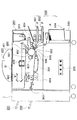
図40は、本実施の形態によるシート処理装置を備える画像形成装置(複写装置)システムの1例による概略構成を模式的に示す全体断面図である。
【0019】
この図に示す装置構成において、本画像形成装置(複写装置)300は、制御装置(移送動作制御手段を含む)310を有し、該画像形成装置300には、自動給送される複写元原稿Dの読み取りのためのプラテンガラス等の原稿載置台401、光源402及びレンズ系403等からなる原稿読取り部400と、画像形成用シートPの給紙部500と、画像形成部600と、画像形成されて排出ローラ対302から排出される画像形成済のシートPを処理して積載するシート処理装置1が備えられ、該シート処理装置1の排出側には、スタックトレイ(第2の積載トレイ)200、及びサンプルトレイ201が設けられている。
【0020】
ここで、前記給紙部500には、シートPの所要枚数を収載して装置本体に着脱自在に装着されるカセット501,502と、ペデスタル503に配置されるデッキ504とが設けられる。また、前記画像形成部600には、円筒状をした回転自在な感光体ドラム601と、その回りに配置される一次帯電器602、露光部603、現像器604、転写用帯電器605、分離用帯電器606、及びクリーナ607等が設けられると共に、画像形成部600の下流側に搬送装置301を介して定着器608が配されている。
【0021】
上記構成による画像形成装置300の動作について述べる。
【0022】
装置本体内の制御装置310から給紙信号が出力されると、給紙部500のカセット501,502またはデッキ504からシートPの給紙が開始され、かつ画像形成部600の感光体ドラム601が回転を始める。一方、原稿載置台401上に載置されている原稿Dの画像が光源402からの光で読み取られ、レンズ系403を経て感光体ドラム601面に照射される。この状態で感光体ドラム601は、一次帯電器602を用いることであらかじめ帯電されており、該感光体ドラム601への読取り光の照射によってドラム面に静電潜像が形成されると共に、該静電潜像は、現像器604のトナーで現像され、対応するトナー像が形成される。
【0023】
給紙部500から給紙されるシートPは、レジストローラ505によって斜行が補正され、かつタイミングが合わされて画像形成部600に給送される。ついで、画像形成部600では、感光体ドラム601面のトナー像が、転写用帯電器605によってシートP上に転写された後に、該トナー像が転写されたシートPは、分離用帯電器606で逆極性に帯電されて、感光体ドラム601面から分離される。
【0024】
その後、シートPは、搬送装置301によって定着器608に搬送され、該定着器608で転写画像が永久定着される。そして、このように画像形成されたシートPは、排出ローラ対302によってシート処理装置1側に排出されるのである。
【0025】
続いて、本発明に係るシート処理装置について説明する。
【0026】
《シート処理装置の全体の概要説明》
まず、本シート処理装置の主要な各部構成について述べる。
【0027】
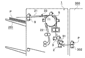
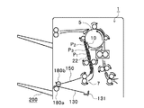
図1は、本実施の形態によるシート処理装置の概略構成を模式的に示す全体断面図である。
【0028】
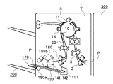
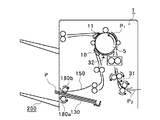
この図に示すシート処理装置(以下「フィニッシャ」という)1の構成において、符号2は、前記画像形成装置300の排出ローラ対302から排出されてくるシートPを受け入れる入口ローラ対、3は、受け入れたシートPを搬送する第1の搬送ローラ対であって、31は、該シートPの通過を検知する入口側でのシート検知センサである。また、50は、搬送されてくるシートの後端部付近に穴あけをするパンチユニットである。5は、搬送途上に配置される比較的大径のローラ(以下「バッファローラ」という)であり、外部周囲に配した各押付けコロ12,13,14でロール面にシートPを押し付けて搬送する。
【0029】
11は、第1の切替えフラッパであって、ノンソートパス21とソートパス22とを選択的に切り替える。10は、第2の切替えフラッパであって、ソートパス22とシートPを一時的に蓄えるためのバッファパス23との切り替えを行うようになっている。33は、ノンソートパス21内のシートPを検知するシート検知センサ、32は、バッファパス23内のシートPを検知するシート検知センサである。
【0030】
6は、ソートパス22の経路に設けられる第2の搬送ローラ対、129は、シートPを一時的に集積し、該集積されるシートPを整合すると共に、ステイプルユニット100のステイプラ101によってステイプル処理を行うために設けられる中間トレイ(以下「処理トレイ」という)130を含む処理トレイユニットであり、処理トレイ(第1の積載トレイ)130の排出端側には、束排出ローラ対(移送手段)を構成する一方の排出ローラ、ここでは、固定側としての下排出ローラ180aが配されている。
【0031】
7は、ソートパス22に配されてシートPを処理トレイ(第1の積載トレイ)130上に排出させるための第1の排出ローラ対であり、9は、ノンソートパス21に配されてシートPをサンプルトレイ201上に排出させるための第2の排出ローラ対である。
【0032】
180bは、揺動ガイド150に支持されていて、該揺動ガイド150が閉じ位置に作動されたときに、前記下排出ローラ180aに加圧的に当接されて処理トレイ130上のシートPをスタックトレイ(第2の積載トレイ)200上に束排出するための上排出ローラである。40は、スタックトレイ200及びサンプルトレイ201上に積載されるシート束の後端縁(束排出方向に対して後端縁)を突き当て支持する束積載ガイドであり、ここでは、シート処理装置1の外装面を兼ねている。
【0033】
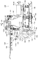
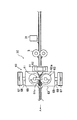
《ステイプルユニットの詳細説明》
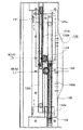
次に、前記ステイプルユニット100につき、特に、図2(主断面該当の側面図)、図3(図2のa矢視方向平面図)及び図4(図2のb矢視方向背面図)を参照して詳細に説明する。
【0034】
ステイプラ(綴じ手段)101は、ホルダ102を介して移動台103上に固定されている。
【0035】
移動台103は、処理トレイ130上に積載されるシートの後端縁に対して平行に固定された1組のスタッド軸104,105を有し、各スタッド軸104,105には、それぞれに転動コロ106,107が回動自在に組み付けられており、該各転動コロ106,107は、固定台108に対して同様に平行状態で穿設形成された一連の穴状ガイドレール108a,108b,108c内に移動可能に係合してある。
【0036】
各転動コロ106,107は、共に一連の穴状ガイドレール108a,108b,108cの穴幅よりも大径のフランジ106a,107aを有し、一方、ステイプラ101を保持する移動台103の下面側には、3ヵ所に支持コロ109が設けらており、該移動台103は、一連の穴状ガイドレール108a,108b,108cに沿って固定台108上を移動する。
【0037】
ここで、前記一連の穴状ガイドレール108a,108b,108cは、図3から明らかなように、主ガイドレール穴部分(108a)と、該部分の左端部側から分岐して平行する左端ガイドレール穴部分(108b)及び右端部側から分岐して平行する右端ガイドレール穴部分(108c)とからなる形状に形成されている。
【0038】
従って、該各部のレール穴形状のために、ステイプラ101が左方端部側に位置するときには、転動コロ106がレール穴部分108bの左端部内に、転動コロ107がレール穴部分108aの左端部内にそれぞれ移動されて、右方側に所定角度だけ傾斜された状態の右傾姿勢に維持され、また、中間部に位置するときには、各転動コロ106,107が共にレール穴部分108a内にあって非傾斜状態の平行姿勢に維持され、さらに、右方端部側に位置するときには、転動コロ107がレール穴部分108cの右端部内に、転動コロ106がレール穴部分108aの右端部内にそれぞれ移動されて、左方側に所定角度だけ傾斜された状態の左傾姿勢に維持されることになり、これらの姿勢変更の作用は不図示の作動カムによって行われる。
【0039】
なお、ステイプルユニット100には、ステイプラ101のホームポジションを検知する不図示の位置センサが設けられており、通常の場合、ステイプラ101は、左方端側のホームポジションで待機している。
【0040】
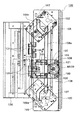
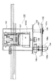
《ステイプラ移動機構の詳細説明》
次に、前記ステイプラ101の移動機構について詳細に説明する。
【0041】
前記移動台103の一方の転動コロ106には、フランジ106aの下方でピニオンギア106bが一体に形成され、かつ上方にベルトプーリ106cが一体化して設けられている。ピニオンギア106bは、台面上の駆動モータM100の出力プーリとベルトプーリ106cとの間に張架した駆動ベルトを介して連繋されると共に、前記レール穴に添わせて固定台108に固定したラックギア110に噛合させてあり、移動台103は、駆動モータM100の正逆回転に対応してステイプラ101と共々にシート幅方向へ移動可能にされる。
【0042】
また、移動台103の下面から下方へ伸びるスタッド軸111には、ストッパ倒しコロ112が設けられており、該ストッパ倒しコロ112は、その詳細については後述するが、前記処理トレイ130の後端ストッパ131とステイプラ101との衝接を避けるために、該後端ストッパ131を回動させる役割りを担っている。
【0043】
《後端ストッパの詳細説明》
次に、前記処理トレイ130上でのシートPの後端縁を突き当て支持する後端ストッパ131について詳細に説明する。
【0044】
後端ストッパ131は、処理トレイ130の積載面に対して垂直に立ち上げて形成され、シートPの後端縁を突き当て支持する突当て支持面131aを有しており、該突当て支持面131aは、処理トレイ130の下面側で枢支ピン131bを中心に矢印で示す下方側へ揺回動可能にされている。
【0045】
また、前記ストッパ倒しコロ112が当接して押圧作動されるカム面132aを備えた主リンク132は、突当て板136に突き当てて位置されると共に、不図示のフレーム等に固定した軸134を中心に引っ張りばね135に抗して揺回動可能にされると共に、上端部のピン132bに対しては、一端部を後端ストッパ131にピン131cで枢支した連結リンク133の他端部長孔に摺動可能に連繋させてある。
【0046】
従って、この場合、移動台103の移動に伴い、ステイプラ101と干渉関係におかれる後端ストッパ131については、該移動台103のストッパ倒しコロ112が主リンク132のカム面132aを押圧することで、図に2点鎖線で示す不干渉位置へ揺回動され、これによってステイプラ101との衝接が回避される。
【0047】
そして、後述するステイプル処理の終了後、移動台103がホームポジション位置に復帰することで、後端ストッパ131もまた元の状態に復帰する。この場合、ストッパ倒しコロ112については、ステイプラ101の作動中、後端ストッパ131を回避位置に保持させておくために、移動台103の移動方向に複数個(ここでは3個)が配設されている。
【0048】
また、ステイプラ101を保持するホルダ102の両側面には、後端ストッパ131の突き当て支持面131aと同様な形状の支持面をもつステイプルストッパ(図2に二点鎖線で表示)113が付設されており、後端ストッパ131が回避位置にあってもシート後端縁の支持が可能にされている。
【0049】
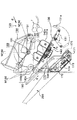
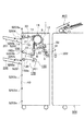
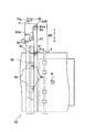
《処理トレイユニットの概要説明》
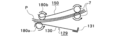
次に、前記処理トレイ130を含む処理トレイユニット129につき、図5に基づいて詳細に説明する。
【0050】
処理トレイユニット129は、処理トレイ130と、後端ストッパ131と、整合手段140と、揺動ガイド150と、引込みパドル160と、出没トレイ170と、それに、束排出ローラ対180とによって構成されている。
【0051】
この場合、前記処理トレイ130については、シート束の排出方向に対して下流側(図5の左上方側)を上方に、上流側(図5の右下方側)を下方に位置させることで傾斜状態に設定しており、上流側である下方端部には、上述の後端ストッパ131が配置され、中間部には、その左右位置を占めて後述する引込みパドル160を含んだ整合手段140が配置され、また、下流側である上方端部、詳しくは実質的にユニット構成の上方領域部分には、後述する引込みパドル160と束排出ローラ対180とを含んだ揺動ガイド150が配置され、さらに、下流側である上方端部、詳しくは実質的にユニット構成の下方領域部分でかつ前記スタックトレイ200の間にあっては、後述する出没トレイ170が配置されている。
【0052】
そして、前記第1排出ローラ対7から排出されるシートPは、自身の自重及び後述する引込みパドル160の作用によって、該シートPの後端縁が後端ストッパ131の突当て支持面131aに突き当てられるまで、処理トレイ130上を滑走する。
【0053】
さらに、処理トレイ130の上方端部には、先にも述べたように、束排出ローラ対180を構成する一方の下排出ローラ180aが配置され、かつ前記揺動ガイド150の下面前端部には、該下排出ローラ180aに離接自在に当接される他方の上排出ローラ180bが配置されており、これらの各排出ローラ対180a,180bは、駆動モータM180で正逆回転可能にされている。
【0054】
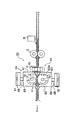
《整合手段の詳細説明》
次に、前記整合手段140につき、図5及び該図5のc矢視図である図6に基づいて詳細に説明する。
【0055】
整合手段140を構成する1組の整合部材141,142は、前記処理トレイ130面上で図の下方部と上方部(シートPの両側端に対応)とに独立して対向配置されると共に、一方の下方側での第1の整合部材141、及び他方の上方側での第2の整合部材142は、それぞれにシート側端面を押圧して支持するための、処理トレイ130面に対して垂直な各整合面141a,142aと、シート裏面を支持するためのラックギア部141b,142bとを有しており、該各ラックギア部141b,142bは、処理トレイ130面に開穿した上下方向(シートPの幅方向に対応)に平行な1組のガイド溝130a,130bを通して下面側に配置される。
【0056】
すなわち、これを要約すると、処理トレイ130に対して、その上面側に各整合面141a,142aが対向して配置され、かつその下面側に各ラックギア部141b,142bが整合方向に移動可能なように組み付けられている。
【0057】
そして、各ラックギア部141b,142bに対しては、それぞれの各駆動モータM141,M142によって正逆回転可能に駆動される個々のピニオンギア143,144が噛合されており、これによって第1,第2の整合部材141,142がそれぞれに整合方向へ移動可能にされることになる。ここで、第1,第2の各整合部材141,142に対しては、それぞれのホームポジションを検知するための不図示の位置センサが配置されており、通常の場合、第1の整合部材141が下方端部、第2の整合部材142が上方端部に設定された各ホームポジション位置に待機している。
【0058】
《揺動ガイドの詳細説明》
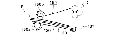
次に、前記揺動ガイド150について詳細に説明する。
【0059】
揺動ガイド150は、先に述べたように下流側(図5の左側)に対応する下面前端部にあって、前記束排出ローラ対180の下排出ローラ180aに当接する上排出ローラ180bを枢着すると共に、上流側(図5の右側)に対応する下面後端部の支持軸151で枢支して揺動自在に支持されており、揺動ガイドモータM150による回転カム152の制御駆動で揺動可能にされると共に、ここでは、下排出ローラ180aに上排出ローラ180bを当接させた閉口状態(図5に二点鎖線で表示)がホームポジションとされ、これを検知する不図示の位置センサが設けられる。
【0060】
そして、通常の場合、個々の各シートPが処理トレイ130上に排出される際には、開口状態(下排出ローラ180aに対して上排出ローラ180bが離間、揺動ガイド150の上方への揺動)に移行されて、該シートPの排出と整合との各動作、ならびに次に述べる引き込みパドル動作を支障なく行い得るようにし、また、処理トレイ130上での処理を終了したシート束を前記スタックトレイ200上へ排出する際には、閉口状態(下排出ローラ180aに対して上排出ローラ180bを当接、揺動ガイド150の下方への揺動)に移行する。
【0061】
《引き込みパドルの詳細説明》
次に、前記引き込みパドル160について詳細に説明する。
【0062】
引き込みパドル160は、前記処理トレイ130の上方にあって駆動軸161に固定され、駆動モータM160によって適切なタイミングで図5における反時計方向に回転駆動されるようになっており、各パドルの長さが処理トレイ130面までの間隔よりも若干長めに設定されると共に、そのホームポジションは、前記第1排出ローラ対7から処理トレイ130上へのシートPの排出の障害にならない位置(図5の実線表示位置)に設定されている。
【0063】
そして、この状態で処理トレイ130上へのシートPの排出がなされると、引き込みパドル160が反時計方向に回転駆動されることで、該処理トレイ130上に排出されるシートP、ひいては該シートPの後端縁が後端ストッパ131の突当て支持面131aに突き当てられるまで引き込むのであり、その後、所定時間を待って不図示の位置センサで検知される前記ホームポジション位置にタイミングよく停止する。
【0064】
《出没トレイの詳細説明》
次に、前記出没トレイ170につき、図5及び該図5のd矢視図である図7に基づいて詳細に説明する。
【0065】
出没トレイ170は、束排出ローラ対180の内、下排出ローラ180aの下側に位置されており、処理トレイ130の傾斜にほぼ沿わせた態様でシート束の排出方向(図5,7のX方向)に進退して出没作動される。
【0066】
すなわち、突出位置では、先端がスタックトレイ200の上部側に突出(図5に二点鎖線で表示)され、退避位置(ホームポジション位置)では、先端が下排出ローラ180aよりも内側に引き込まれて退避する(図5の実線表示位置)もので、突出状態では、処理トレイ130上に排出されるシートPの重心が該位置を超えることのないように、換言すると、突出位置でシートPの先端突出部側が下方へ垂れ下がらないように位置設定されている。
【0067】
そして、この出没トレイ170は、支持フレーム171に固定された1対のガイドレール172,172上に摺動可能に支持されており、回転軸174を中心にして回転される回転カムコロ173が、出没トレイ170の下面溝175内に係合されていることから、駆動モータM170による該回転カムコロ173の回転作動に伴って上述の如くに出没操作されるもので、常態では、不図示の位置センサで検知される前記ホームポジション位置に待機する。
【0068】
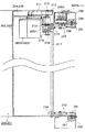
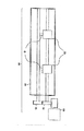
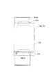
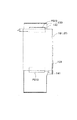
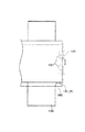
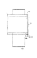
《スタッスタックトレイ及びサンプルトレイの詳細説明》
次に、前記スタックトレイ200及びサンプルトレイ201につき、図8及び図9に基づいて詳細に説明する。
【0069】
スタックトレイ200及びサンプルトレイ201は、状況に応じてそれぞれに使い分けられるもので、下方に配されるスタックトレイ200が、コピー出力、プリンタ出力等におけるシート束を受け取るときに選択され、上方に配されるサンプルトレイ201が、サンプル出力、割り込み出力、スタックトレイのオーバーフロー時の出力、ファンクション出力、ジョブ混載時の出力等でのシートを受け取るときに選択される。
【0070】
そして、これらのスタックトレイ200及びサンプルトレイ201は、それぞれにトレイベースプレート202,203に保持されると共に、該各ベースプレート202,203に取付け枠板204,205を介して固定したステッピングモータM200,M201を用いることで、個々に独立して上下の昇降方向へ自走可能にされており、この場合、これらの双方共に、ほぼ同一の態様に構成されることから、ここでは、主にスタックトレイ200側の場合についてのみ特定して述べる。
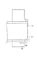
【0071】
すなわち、前記シート処理装置1の両端部には、1対のフレーム250,250が上下方向に設けられると共に、該フレーム250,250に対してそれぞれに上下方向のガイドレール部を兼ねるラックギア部材251,251が取り付けられており、前記トレイベースプレート202の一方(シート幅方向を基準にして左端側に対応)から延長された後端部と、これに対向(同様に右端側に対応)する取付け枠板204から延長された後端部とにそれぞれ回転自在に設けられている1対のガイドコロ206,207を用い、該各ガイドコロ206,207を対応する各ガイドレール部内に嵌挿させることで、前記スタックトレイ200を上下に昇降可能に保持させ、かつ一方のフレーム250の折り返された端縁に規制部材208を係合させることで、シート幅方向のガタつきを拘束して規制するようにしている。
【0072】
一方、ステッピングモータM200の回転出力は、タイミングベルト211を介して駆動軸213のプーリ212に伝達される。そして、駆動軸213には、ばね216で付勢されて軸方向に摺動のみ可能にしたラチエットホイール215が設けられており、該ラチエットホイール215は、軸上の駆動ギア214に一方向係合させてある。
【0073】
また、駆動ギア214に対しては、従動軸217上の両端部に配した各アイドラギア218,218の一方が噛合され、かつ該各アイドラギア218,218は、それぞれに昇降ギア219,219を介して前記ラックギア部材251,251に噛合させる。つまり、前記スタックトレイ200は、これらのギアトレーンからなる駆動系を介して上下方向に昇降自在にされる。
【0074】
また、前記駆動軸213上の駆動ギア214に一方向付勢係合されるラチエットホイール215は、前記スタックトレイ200の下降時にあって、例えば、異物等を挟んで駆動系が破損したりすることのないように設けられるもので、ここでは、ばね216に所要程度の付勢力を付与しておき、該スタックトレイ200の上昇時においてのみ、あらかじめ設定されている条件対応にばね216の付勢力に抗し空回りすることで防護するようになっており、この空回りの状況、つまり、異常が発生した場合には、直ちにステッピングモータM200の駆動を停止させるべく、アイドラギア218のフランジ部に形成したクロックスリット等をセンサS201によって検出させるようになっている。なお、センサS201に関しては、通常動作時における脱調検知のためにも用いられる。
【0075】
続いて、前記スタックトレイ200及びサンプルトレイ201の昇降位置制御のための各センサ配置(図9に詳細を表示)について述べる。
【0076】
センサS202は、サンプルトレイ201の積載エリア検知のためのセンサであり、該サンプルトレイ201の上昇限位置検知センサS203aから処理トレイシート面検知センサS205までのエリアに属する範囲に位置していることを検知する。
【0077】
センサS203bは、第2の排出ローラ対9からサンプルトレイ201上に排出されるシートPが所定枚数に達したことを検知のためのセンサであり、ここでは、ノンソートシート面検知センサS204からシート積載枚数1000枚相当の位置に配置される。
【0078】
センサS203cは、処理トレイ130からサンプルトレイ201上に排出されるシートPが所定枚数に達したことを検知のためのセンサであり、同様に、シート面検知センサS205からシート積載枚数2000枚相当の位置に配置される。
【0079】
センサS203dは、スタックトレイ200が処理トレイ130からシートPを受け取るときの積載量の高さを制限するためのセンサであり、シート面検知センサS205からシート積載枚数2000枚相当の位置に配置される。
【0080】
センサS203eは、スタックトレイ200の下降限位置を設定するセンサである。
【0081】
また、スタックトレイ200及びサンプルトレイ201には、それぞれにシート有無検知センサ206a,206bが配置されている。
【0082】
そして、これらの各センサの内で、シート面検知センサS204,S205のみが、シートPの一方の側縁から他方の側縁への光透過によってその有無を検知する光透過型に設定されており、ここでは、そのシート面検知手法として、各シート面検知センサS204,S205の下方から、これを覆う位置まで各トレイ200,201を上昇させた状態がイニシャルであり、シート積載後にセンサ光軸が現れるまで下降させ、その後、再びセンサ光軸を覆うまで上昇させることを繰り返すのである。
【0083】
《パンチユニットの詳細説明》
次に、前記パンチユニット50につき、図10ないし図14に基づいて詳細に説明する。
【0084】
パンチユニット50は、穿孔手段60と横レジ検知手段80とによって構成されている。
【0085】
穿孔手段60には、所要組み数、ここでは左右1対のパンチ部材61と、該各パンチ部材61に組み合わされる各ダイス部材62とが左右方向(シートの幅方向に対応)に所定のパンチ間隔でケーシング63内に配置されると共に、その軸上の各連動ギア64,65が相互に噛合されており、パンチングモータ66の駆動で相互に矢印B,Cで示す方向に同期して回転可能に構成され、常態では、図10のホームポジション位置に待機する。
【0086】
この状態で、前記シート検知センサ31(図1及び図13,14参照)が導入されるシートPの後端を検知した後に、所定のタイミングでパンチングモータ66を駆動させることにより、パンチ部材61のパンチ突出片61aとダイス部材62のダイス穴部62bとが噛み合い係合されてシートPの対応部分に所期通りのパンチ穴を穿孔する。そして、この場合、パンチ部材61とダイス部材62との回転速度を前記第1の搬送ローラ対3(図1参照)の回転速度、ひいては、シートPの矢印A方向の搬送速度に一致させることで、搬送途上での同時パンチングが可能である。
【0087】
一方、これらのパンチ部材61及びダイス部材62を抱持するパンチケーシング63は、上下位置にあって支持軸69,69で回転自在に支持された各ガイドコロ68,68を有しており、該各ガイドコロ68,68をシートPの幅方向に平行なそれぞれの各ガイドレール67,67に嵌挿させて該当方向への移動を可能にすると共に、図13,14に示すように、一方の端部側面に形成したラックギア63aに対して、不図示の穿孔手段移動モータで回転駆動されるピニオンギア70を噛合させ、さらに、該端面に受光部71aをもつ穿孔手段イニシャル位置検知センサ71を配してある。
【0088】
このため、穿孔手段60は、穿孔手段移動モータの駆動でシートPの搬送方向Aに直交する矢印D,E方向(シートPの幅方向)に移動され、該移動に伴い穿孔手段イニシャル位置検知センサ71によって装置本体側の穿孔手段イニシャル位置規定部52を検知し得るもので、この場合、穿孔手段イニシャル位置は、シートPの斜行や横レジのずれ量に相当するシート基準位置の数mm手前側に設定する。
【0089】
また、横レジ検知手段80は、前記穿孔手段60の一端部側に併設されて、側縁のラックギア82aに不図示の横レジ移動モータで回転駆動されるピニオンギア83を噛合させることで、同様にシートPの搬送方向Aに直交する矢印D,E方向(シートPの幅方向)に移動可能なセンサアーム82を有しており、該センサアーム82のシートPに近付けた一端側には、該シートPの一方の側縁を検出する受光部81aをもつ横レジ検知センサ81が設けられ、他端側には、受光部81aに対向する受光部84aをもつ横レジイニシャル位置検知センサ84が設けられている。
【0090】
このため、横レジ検知手段80は、前記穿孔手段60の場合と同様に、横レジ移動モータの駆動でシートPの搬送方向Aに直交する矢印D,E方向(シートPの幅方向)に移動され、該移動に伴い横レジイニシャル位置検知センサ84によってパンチケーシング63の該当端面相当の横レジイニシャル位置規定部63bを検知し得るもので、この場合、横レジ検知センサ81を矢印D方向に移動させることにより、選択されたシートサイズに対応する位置に該横レジ検知センサ81をセットできる。
【0091】
ここで、シートの側端部を検知する際は、前記シート検知センサ31がシート先端を検知した後、所定のタイミングで穿孔手段移動モータを駆動し、穿孔手段60、及び横レジ検知センサ81を矢印方向に移動させ、該横レジ検知センサ81の受光部81aがシートの側端部によって遮られることで、これをシートの側端部と検知して停止する。
【0092】
すなわち、これによって穿孔位置をシートの側端部側に揃えることが可能になるのである。
【0093】
《シート処理装置の全体の作用説明》
次に、本シート処理装置の主要な各部の作用(動作)について述べる。
【0094】
《整合動作の説明》
図15は、シート束の各整合部材による整合動作準備の態様を示す平面説明図である。図16は、1部目(奇数部目)の整合動作状態を示す平面説明図、図17は、2部目(偶数部目)の整合動作状態を示す平面説明図である。図18は、シート束の仕分け積層状態を示す側面説明図、図19は、一例による整合不良の態様を示す部分説明図である。
【0095】
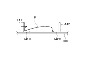
上記画像形成装置300側から、最初の画像形成されたシートが処理トレイ130上に排出される際にあって、図15に示されているように、それまでホームポジションで待機していた各整合部材141,142は、該排出動作の事前に、排出されるシート幅に対して若干余裕のある整合待機位置PS11,PS21へ移動して待機する。
【0096】
先に述べたように、処理トレイ130上に排出されるシートPが、その後端縁をストッパ131に突き当てることで支持され、かつシートPの下面が、各整合部材141,142の支持面141C,142C(図19を参照)に接した時点で、これらの各整合部材141,142は、図16に示されているように、整合位置PS12,PS22へ作動して、該排出されたシートPを第1の整合位置190へ移動かつ整合させる。
【0097】
その後、一方の整合部材141は、次に排出されるシートPに備えるために、一旦、整合待機位置PS11へ復帰した上で、次のシートPの排出を待ち、他方の整合部材142は、整合位置PS22で停止したまま待機することで、整合基準位置の役割を果たす。この状態で、該シートPの排出完了に伴い、先に整合待機位置PS11に復帰されている一方の整合部材141は、再度、整合位置PS12へ作動して、同様に、シートPを第1の整合位置190で整合する。
【0098】
以上の動作が、排出されてくる最終シートPまで続けられ、このようにして該当する1部目のシート束Paの排出ならびに整合が完了すると、後述の各処理ならびに束排出がなされ、これがスタックトレイ200へ移送される。
【0099】
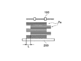
引続き、次の2部目に該当するシートPが処理トレイ130上に排出されてシート束Paを形成する。この場合にも、各整合部材141,142は、1部目の場合と同様に作用してシートPを整合するが、このとき、各整合部材141,142の対応する各整合位置は、図17に示されているように、一方の整合部材141が整合位置PS13に、他方の整合部材142が整合位置PS23にそれぞれ位置されており、従って、この2部目のシート束Paの整合位置は、1部目での第1の整合位置に対して所定量(距離L)だけずらされた(仕分けされた)第2の整合位置191へ移されることになる。
【0100】
以後、シート束Pa毎、つまり、奇数部目と偶数部目とでそれぞれに整合位置190,191を変えながらスタックトレイ200上への束積載を行うことにより、図18に示すように、オフセット距離Lの仕分けがなされる。
【0101】
そして、このオフセット距離Lは、ソートモードと、ステイプルソートモードとでそれぞれに変化させる。すなわち、例えば、ステイプルソートモードでは、積載後に隣り合った針同士の重なりが防げるだけの量L1に設定し、ソートモードでは、確実に束識別が可能な量L2に設定してある。また、この場合、それぞれの各量の関係をL1<L2となるように設定することで、ステープルソートモード時の高速化を図り得るのである。
【0102】
また、上記のように、整合時にあって各整合部材141,142に対し、それぞれの整合待機位置PS11,PS21を設定することにより、図19に示すようなシートPに対する整合不良等を生じさせる惧れがない。
【0103】
《ステープル動作の説明》
図20ないし図22は、個々に異なった位置(中央部位置、右隅部位置及び左隅部位置)でのステープル状態をそれぞれに示す各平面説明図である。
【0104】
ステープルモード時にあって、ステープラ101は、整合されたシートPに対して所望のクリンチ位置であらかじめ待機しており、束毎の最終シートPの排出ならびに整合が完了した時点で、所期通りのステイプル動作を行う。
【0105】
そして、この場合にも、ステープラ101は、シート束Pa毎の前記オフセット移動(移動量L1)に同期してオフセット移動を行うもので、各図中、二点鎖線が第1の整合位置、実線が第2の整合位置に対応する。このとき、排出位置よりも左側に整合位置がある場合には、整合部材142が往復移動して、整合基準位置である整合部材141側ヘシートPを移送し、また、排出位置よりも右側に整合位置がある場合には、整合部材141が往復移動して、整合部材142側へシートPを移送する。
【0106】
また、ステイプラ101が、それぞれの各綴じモード(中央部2ヶ所位置の綴じモード、右隅部斜め位置の綴じモード及び左隅部斜め位置の綴じモード)に対応して、向きを変えたり、移動したりするそれぞれの各動作については、先に述べた通りである。
【0107】
《ステープルモード時の束排出動作の説明》
1ヶ所ステープルソートモード時には、上記整合動作が終了した時点で、ステープル動作を開始する。そして、整合動作中、またはステープル動作中に揺動ガイド150の降下が始まり、該ステープル動作の終了と前後して束排紙上ローラ180bが、シート束Pa上に当接されるように、揺動ガイドモータM150の速度制御が行われる。
【0108】
揺動ガイド150の降下開始タイミングは、処理トレイ130上のシート束Paの積載枚数によって可変である。すなわち、シート束Paが少数枚である場合には、束排出上ローラ180bがシート束Pa上に当接するまでの移動距離が長いことと、ステープラ101の動作時間が短いことから、整合動作中に揺動ガイド150の降下が始まり、シート束Paの枚数が多い場合には、束排出上ローラ180bがシート束Pa上に当接するまでの移動距離が短いことと、ステープラ101の動作時間が長いことから、揺動ガイド150の降下開始は、ステープル動作開始とほぼ同時に行う。
【0109】
束排紙上ローラ180bがシート束Paに当接してから、束排紙上ローラ180bのバウンドが収まるまでの所定時間を経過させた後に、ステープル動作が終了したか否かを判断し、ステープル動作終了ならば、束排紙モータM180が回転し始め、シート束Paがスタッカトレイ200に排出されてゆき、ステープル動作が完了していない場合は、ステープル動作終了待ちの状態となる。
【0110】
このとき、シート束Paの排出速度については、次のように制御する。すなわち、束搬送開始後は高速で搬送するが、シート束Paの後端が束排紙ローラ180を抜ける前に減速して、スタッカトレイ200上にシート束Paを排出する際には、該スタッカトレイ200上への積載に適した速度になるようにする。
【0111】
また、出没トレイ170は、束排出中、シート束Paの後端が束排出ローラ180のニップ部を抜けるまでにホームポジションに戻って待避状態となり、かつ束排出が終了すると、該出没トレイ170は、再度、突出状態となって、次のシート束Paの受け入れを可能にする。
【0112】
一方、2ヶ所ステープルソートモード時には、ステープラ101による1ヶ所目のステープル動作が終了し、該ステープラ101が2ヶ所目の綴じ位置に移動するときに、揺動ガイド150の降下が開始する。そして、2ヶ所目をステープルしている間は、束排紙上ローラ180bがシート束Paに当接した状態で待機しており、該2ヶ所目のステープル終了と同時に束排出動作を開始する。以後の動作は一ヶ所綴じの場合と同じである。
【0113】
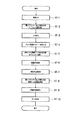
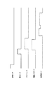
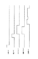
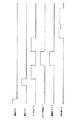
ちなみに、図35には、1ヶ所少数枚ステープルモード時での束排出動作のタイミング図を、図36には、1ヶ所多数枚ステープルモード時での束排出動作のタイミング図を、図37には、2ヶ所ステープルモード時での束排出動作のタイミング図をそれぞれに示してあり、また、図38には、同上ステープルモード時での束排出動作のフローチャートを示してある。
【0114】
《スタックトレイ、サンプルトレイの動作説明》
次に、上記図9を用いてスタックトレイ200、及びサンプルトレイ201の動作について説明する。
【0115】
動作開始前、これらの各トレイ200,201は、該当するそれぞれの各紙面検知センサS205,S204位置で待機している。
【0116】
処理トレイ130で整合されたシート束Paは、順次にスタックトレイ200に束排出されてくる。該排出されてくるシート束Paは、その排出方向後端が束積載ガイド40に突き当てられるように、その排出速度の制御がなされる。
【0117】
束排出動作が終了すると、スタックトレイ200が降下を開始し、シート検知センサS206aがオンしたところから、所定量相当に降下したところで一旦、停止する。その後、スタックトレイ200は上昇し、シート検知センサS206aが再度、OFFされた(光軸が遮断された)ところで停止して待機し、次のシート束Paを受け入れ可能にする。
【0118】
そして、前記スタックトレイ200は、処理トレイ130側からシート束Paが排出される毎に上記の動作を繰り返すが、スタックトレイ200上に積載可能なシート束数には限りがあり、この限界束数(積載規定束数)を超えてシート束Paが積載された場合は、以下の動作を行う。
【0119】
すなわち、この状態では、スタックトレイ200のベースプレート211がセンサS203dの位置に達する。ここで、該センサS203dがONすると、満載状態のスタックトレイ200は、下限センサS203e側に向けてさらに下降し、これと同時に、サンプルトレイ201は、その積載面が紙面検知センサS205にかかるまで下降する。これによって、積載規定束数を超えるシート束Paが連続して排出されてきたとしても、スタックトレイ200に代えてサンプルトレイ201上に積載されるようになる。
【0120】
さらに、束排出が続けられて、サンプルトレイ201のトレイ面がセンサS203Cの位置に達すると、該サンプルトレイ201の積載限界に達したものと判断し、画像形成装置300に対して積載束数の超過を意味するアラームを発することになり、該画像形成装置300では、このアラームを受けて画像形成動作を一時的に中断する。
【0121】
そして、このアラーム状態は、スタックトレイ200またはサンプルトレイ201に設けられている各シート検知センサS206a,S206bの何れかがOFFされて、該スタックトレイ200またはサンプルトレイ201の何れかが、後続するシート束Paを受け入れ得る状態になるまで続く。
【0122】
すなわち、例えば、スタックトレイ200側のシート検知センサS206aがOFFされた場合には、まず、サンプルトレイ201の積載面を紙面検知センサS204が検出するまでの間、該サンプルトレイ201を上昇させ、続いて、紙面検知センサS205がスタックトレイ200の積載面を検出するまでの間、該スタックトレイ200を上昇させる。この状態で、処理トレイ130側からのシート束Paの受け入れが可能となるために、アラーム状態を解除し、画像形成装置300に対してレディ信号を出力する。
【0123】
また、サンプルトレイ201側のシート検知センサS206bが先にOFFされた場合には、紙面検知センサS205がサンプルトレイ201の積載面を検知するまでの間、該サンプルトレイ201を上昇させる。従って、この状態でも、処理トレイ130側からのシート束Paの受け入れが可能となるために、同様にアラーム状態を解除し、画像形成装置300に対してレディ信号を出力する。
【0124】
《ノンソートモード時でのシートの流れの説明》
次に、ノンソートモード時でのシートの流れについて説明する。
【0125】
図23は、ノンソートモード時でのシートの流れを示す動作説明図である。
【0126】
ユーザによって、画像形成装置300の排紙モードの設定が、ノンソートモードに指定された場合には、入口ローラ対2、第1の搬送ローラ対3、及びバッファローラ5のそれぞれが図示矢印に示す搬送方向に回転され、画像形成装置300側から搬送されてくるシートPを搬送する。
【0127】
この場合、第1の切替えフラッパ11は、シートPをノンソートパス21側に受け入れるべく切替えられており、該ノンソートパス21を通して搬送されるシートPの後端がノンソートパスセンサ33で検知されると、第2の排出ローラ対9が積載に適した速度で回転され、該シートPをサンプルトレイ200上に排出して積載させる。
【0128】
《ステープルソートモード時でのシートの流れの説明》
次に、ステープルソートモード時でのシートの流れについて説明する。
【0129】
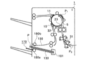
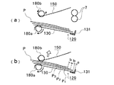
図24及びないし図28は、ステープルソートモード時でのシートの流れを順次に示す動作説明図であり、図29ないし図31(a),(b) は、同上シートの整合動作を順次に示す動作説明図である。
【0130】
ユーザによって、画像形成装置300の排紙モードの設定が、ステープルソートモードに指定された場合には、上記ノンソートモードの場合と同様に、入口ローラ対2、第1の搬送ローラ対3、及びバッファローラ5のそれぞれが図示矢印に示す搬送方向に回転され、画像形成装置300側から搬送されてくるシートPを搬送する。
【0131】
この場合、第1の切替えフラッパ10、及び第2の切替えフラッパ11は、それぞれにシートPをソートパス22側に受け入れるべく切替えられており、シートPの後端がローラ14を抜けたところで、第1の排出ローラ対7の回転駆動によって該シートPを処理トレイ130上に排出させる。このとき、出没トレイ170が作動されて突出位置にあるために、該処理トレイ130上にシートPが排出されても、シートPの垂れ下がりや戻り不良が防止され、併せて、処理トレイ130上でのシートの整列性(整合性)が高められる。
【0132】
続いて、このように処理トレイ130上に排出されたシートPは、自重によって後端ストッパ131側(先に述べているので省略)へ移動し始めると共に、これに加えて、ホームボジションで停止していたパドル160が、モータM160によって反時計方向に回転され、該回転されているパドル160のシートP面に与える擦過作用に伴い、該シートPの後端ストッパ131側への移動を効果的に助長する。
【0133】
また、この状態でシートPの後端が後端ストッパ131に突き当てられると、パドル160の回転が停止され、引続き、各整合部材141,142の作動によって排出されたシートPの整合がなされる。その後、ステープラ101によるステープル動作、ならびに束排出動作が行なわれ、このようにして順次に処理されたシート束Paが処理トレイ200上に排出かつ積載される。
【0134】
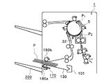
一方、その間に、画像形成装置300から排出されてきたシートP1は、図25に示されているように、第1の切替えフラッパ10のバッファパス23側への切り替えによってバッファローラ5に巻き付けられ、バッファパスセンサ32から所定距離進んだところで停止する。
【0135】
さらに、後続のシートP2の先端が入口センサ31から所定距離進んだところで、図26に示すように、バッファローラ5の回転に伴い、1枚目のシートP1よりも2枚目のシートP2の方が所定距離先行するように重ねあわされた上で、図27に示すように、バッファローラ5に再び巻き付けられ、かつここでもバッファパスセンサ32から所定距離搬送したところで停止する。
【0136】
続いて、図28に示すように、3枚目のシートP3の先端が、入口センサ31から所定距離進んだところで、バッファローラ5が再び回転され、該シートP3をシートP1、シートP2に対して所定距離ずらして重ね合わせると共に、第1の切替えフラッパ10が再度、ソートパス22側に切り替えられ、このようにして重ね合わされた3枚の各シートPをソートパス22に搬送する。
【0137】
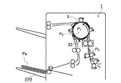
そして、この時点では、先のシート束Paの束排出動作が終了もしくはほぼ終了しており、ここでは、図29に示されているように、揺動ガイド150が下降されたままの状態で、第1の排出ローラ対7の回転駆動、ならびにローラ180a、180bの正転駆動によって重ね合わされた3枚の各シートPを処理トレイ130上に受け入れる。
【0138】
また、図30に示されているように、3枚の各シートPの後端が第1の排紙ローラ対7を抜けて、完全に処理トレイ130上へ受け入れられたところでローラ180a、180bが逆転すると共に、該各シートPの後端が後端ストッパ131に突き当てられる前に、図31(a) に示すように、揺動ガイド150が上昇されて束排出上ローラ180bをシート面から離す。
【0139】
引続き、4枚目以降のシートPについては、1部目のシート排出動作と同様にソートパス22を通って処理トレイ130上に排出される。また、3部目以降のシート束Paは、2部目と同じ動作をし、設定部数対応にスタックトレイ200上に積載する。
【0140】
ここで、前記複数枚のシートPの搬送に際して、該各シートPは、図31(b) に示すように、搬送方向に沿ってオフセットされている。すなわち、シートP2は、シートP1に対してストッパ131側とは逆側にオフセットされ、かつ、シートP3は、シートP2に対して同様にオフセットされている。
【0141】
《ソートモード時でのシートの流れの説明》
次に、ソートモード時でのシートの流れについて説明する。
【0142】
図32及び図33は、ソートモード時でのシートの流れを順次に示す動作説明図である。
【0143】
ユーザによって、画像形成装置300の排紙モードの設定が、ソートモードに指定された場合には、上記ステープルソートモードに指定された場合と同様に、入口ローラ対2、第1の搬送ローラ対3、及びバッファローラ5のそれぞれが図示矢印に示す搬送方向に回転され、画像形成装置300側から搬送されてくるシートPを処理トレイ130上に順次に積載し、以後、ここでも同様な作用が実行される。
【0144】
《シートの割り込みモード時の説明》
次に、シートの割り込みモード時の作用について説明する。
【0145】
ユーザによって、割り込みモードが選択されると、上記ノンソートモードの場合と同様に、シートPは、順次にノンソートパス21側に導かれた上で、第2の排出ローラ対9からサンプルトレイ201上に積載されてゆく。
【0146】
規定枚数のシートPが排出されたところで、該サンプルトレイ201が降下を開始し、シート検知センサS206bがONしたところから所定量降下したところで一旦、停止する。その後、サンプルトレイ201は上昇し、紙面検知センサS206bが再度、OFFされたところで停止して、次のシートPの受け入れを可能にする。
【0147】
そして、第2の排出ローラ対9から規定枚数のシートPが排出される毎に上記の動作を繰り返すが、サンプルトレイ201に積載可能なシート枚数には限りがあり、この限界枚数(積載規定枚数)を超えてシートPが積載された場合には、以下の動作を行う。
【0148】
すなわち、この状態では、サンプルトレイ201のベースプレート211はセンサS203bの位置に達する。センサS203bがONすると、該サンプルトレイ201は、画像形成装置300にアラームを発して、その複写動作を中断させる。
【0149】
次いで、サンプルトレイ201上のシートPが取り除かれ、シート検知センサS206bがOFFされると、該サンプルトレイ201は、所定の位置まで上昇し、画像形成装置300側からのシートPの受け入れが可能な状態となり、前記アラームを解除することで、該画像形成装置300が画像形成を再開する。
【0150】
《パンチモードの説明》
次に、図34のフローチャートに基づいてパンチモードの説明を行う。
【0151】
まず、装置の電源がオンされると(ST−1)、穿孔手段移動モータにより穿孔手段60が図13の矢印Eの方向に移動する。その後、穿孔手段イニシャル位置検知センサ71が穿孔位置規定部52を検出すると、該穿孔手段移動モータが停止して、ここでの穿孔手段60のホームポジション停止制御が完了する(ST−2)。
【0152】
次いで、横レジ移動モータによってセンサアーム82が図13に示すE方向に移動し、横レジイニシャル位置検知センサ84が横レジイニシャル位置規定部63bを検出すると、該横レジ移動モータは停止し、センサアーム82のホームポジション停止制御が完了して入力待ちの状態になる(ST−3)。
【0153】
ここで、ユーザによって、パンチモードが指定され、スタート信号が入力(ST−4)されることで、穿孔手段60が選択されたシートサイズに対応する位置に移動してセットされる(ST−5)。
【0154】
この状態で、画像形成装置300で画像形成(ST−6)されたシートPが搬送されてくると、センサアーム82は図13の矢印D方向に移動し、横レジ検知センサ81を画像形成装置300から搬送されてくるシートPの側端縁付近で停止させる。
【0155】
また、シート検知センサ31が搬送されてくるシートPの先端縁を検出(ST−7)すると、穿孔手段60は、図13の矢印E方向に移動し、横レジ検知センサ81がシートPの側端縁を検出した位置で停止する(ST−8)。
【0156】
引続き、該シート検知センサ31がシートPの後端縁を検出(ST−9)すると、該検出位置から所定距離相当分だけ搬送した後に、パンチ駆動モータ66が回転し、パンチ61、ダイス62によって搬送途上のシートPの後端該当部にパンチ穴が穿孔される(ST−10)のである。
【0157】
その後の動作は、ノンソートモード、ソートモード、ステープルソートモードと同様である。
【0158】
《本実施形態における制御回路の説明》
次に、本実施形態に適用される制御回路の構成及び作用について説明する。
【0159】
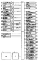
図39は、本実施形態の制御装置の回路構成を示すブロック図である。
【0160】
本実施形態において、制御回路は、マイクロプロセッサ(CPU)401を中心に構成されている。CPU401は、不図示のバックアップ用のEEPROM及び制御シーケンスソフトの格納されたROMを有しており、該CPU401の入出力ポートには、各種負荷に対応するそれぞれの各センサ、及びドライブ回路等が接続されると共に、画像形成装置300とのデータ通信を制御するための通信用IC402を介してフィニッシャ1が接続される。
【0161】
ここで、ソート・ノンソート切替えソレノイドSL1は、ドライバD1によって駆動され、同様に、バッファソレノイドSL2は、ドライバD2によって駆動される。
【0162】
入口モータM1(DCブラシレスモータ)は、モータ一体型ドライバによって駆動制御され、CPU401からのモータ回転数の基準となる基準クロック、ON・OFF、回転方向切替え、ブレーキ、ロック等の各駆動信号が入力される。バッファモータM2(ステッピングモータ)は、ステッピングモータドライバD4によって定電流駆動制御される。同様に、排紙モータM3(ステッピングモータ)は、ステッピングモータドライバD5によって定電流駆動制御される。
【0163】
パンチャ回転駆動モータ66(ステッピングモータ)は、ステッピングモータドライバD6によって定電流駆動制御される。パンチャシフト駆動モータM300(ステッピングモータ)は、ステッピングモータドライバD7によって定電流駆動制御される。
【0164】
パンチャ屑搬送モータM301(DCブラシモータ)は、ドライバD8によって駆動制御され、CPU401からON・OFF信号が入力される。パンチャセンサシフト駆動モータM302(ステッピングモータ)はドライバD9によって定電流駆動制御される。
【0165】
パドル位置決めソレノイドSL3は、ドライバD1Oによって駆動される。基準壁移動モータM141(ステッピングモータ)は、ステッピングモータドライバD11によって定電流駆動制御され、同様に、整合壁移動モータM142(ステッピングモータ)は、ステッピングモータドライバD12によって定電流駆動制御される。
【0166】
パドルモータM160(DCブラシレスモータ)は、モータ一体型ドライバによって駆動制御され、CPU401からのモータ回転のON・OFF、回転方向切替え等の各駆動信号が入力される。出没トレイ駆動モータM170(ステッピングモータ)は、ステッピングモータドライバD14によって定電流駆動制御さる。
【0167】
束排出モータM180(DCブラシモータ)は、ドライバD15とコントローラC15とによって駆動制御されており、コントローラC15には、CPU401からモータ回転数の基準となる基準クロック、ON・OFF等の各駆動信号が入力される。同様に、揺動ガイドモータM150(DCブラシモータ)は、ドライバD16とコントローラC16によって駆動制御されており、コントローラC16には、CPU401からモータ回転数の基準となる基準クロック、ON・OFF等の各駆動信号が入力される。
【0168】
ステイプラ移動モータM100(ステッピングモータ)は、ステッピングモータドライバD17によって定電流駆動制御され、ステイプラモータM101(DCブラシモータ)は、ドライバD18とコントローラC18によって駆動制御されており、コントローラC18には、CPU401からモータ回転数の基準となる基準クロック、ON・OFF等の各駆動信号が入力される。
【0169】
サンプルトレイシフトモータM201(ステッピングモータ)は、ステッビングモータドライバD19によって定電流駆動制御され、同様に、スタックトレイシフトモータM200(ステッピングモータ)は、ステッピングモータドライバD20によって定電流駆動制御される。
【0170】
前記各ドライバD1〜D20は、その全てがCPU401の入出力ポートに接続されており、該CPU401からの対応する各出力信号によって動作制御される。
【0171】
そして、前記制御回路の入出力ポートには、入口センサ31、バッファパスセンサ32、ノンソートパスセンサ33、ソートパスセンサ34及び排紙センサ35が接続されると共に、同様に、横レジセンサ81及び横レジイニシャル位置検知センサ84と、各センサとが接続されて、装置内におけるシートの挙動及び各種可動負荷の挙動を制御ならびにモニタするために用いられる。
【0172】
上記各種のセンサとしては、次の各センサである。
【0173】
すなわち、パンチャHPセンサS106、パンチャ回転HPセンサS108、パンチャ屑満タン検知センサS110、基準壁HPセンサS111、整合壁HPセンサS112、束排出揺動閉検知センサS113、シャッタHPセンサS114、束排出揺動ガイドHP検知センサS115、束排出揺動モータクロック検知センサS116、束排出モータクロック検知センサS117、出没トレイダウン検知センサS118、束排出完了センサS119、ステイプラHPセンサS120、ステイプラホームセンサS121、ステイプラ針無センサS122、ステイプラカートリッジセンサS123、ステイプラセルフプライミングセンサS124及びドアスイッチ作動検知センサS128である。
【0174】
そして、スタックトレイ空回り検知センサS201a、スタックトレイ上位置検知センサS202a、スタックトレイ下位置検知センサS203d、スタックトレイ下限検知センサS203e、スタックトレイ紙面検知センサS205、スタックトレイ紙有無検知センサS206の各センサのそれぞれであり、また、サンプルトレイ空回り検知センサS201b、サンプルトレイ上位置検知センサS202b、サンプルトレイ上限検知センサS203a、サンプルトレイ下位置検知センサS203b、サンプルトレイ下限検知センサS203c、サンプルトレイ紙面検知センサS204、サンプルトレイ紙有無検知センサS206bの各センサのそれぞれである。
【0175】
【発明の効果】
以上、実施の形態によって詳述したように、本発明によれば、排出されるシートを受け入れる第1の積載トレイ手段と、第1の積載トレイ手段上のシート束を整合する整合手段と、整合手段によって整合されたシート束を綴じ処理する綴じ手段と、綴じ手段によって綴じられたシート束を第2の積載トレイ手段上に移送する移送手段とを備えるシート処理装置及びこれを備える画像形成装置の構成において、移送動作制御手段によって、移送手段の移送動作開始を整合手段による整合動作中、または綴じ手段による綴じ動作中に行わせるべく制御するようにしたので、シート束の束処理速度を向上でき、併せて、シート束の束排出の安定性が得られるという利点を有しており、この結果、シート処理装置自体の所要シート処理性能を効果的かつ格段に高めることができる。
【0176】
一方、前記装置構成において、第1の積載トレイ手段上に受け入れるシートの枚数を計数する計数手段と、計数手段の計数結果に対応して移送動作制御手段による動作開始タイミングを可変にするタイミング制御手段とによる構成、移送手段が、第1の積載トレイ手段上のシート束を第2の積載トレイ手段上に搬送する搬送手段と、搬送手段をシート束に当接させる当接作動手段と、当接作動手段による当接動作終了時点から搬送手段による搬送開始時点までの時間を制御する当接起動制御手段とによる構成、それに、当接作動手段の移動速度を制御する当接速度制御手段の構成をそれぞれに備えるときは、上記シート処理装置における作用をより一層、効果的に助長し得る。
【0177】
また、本発明によれば、処理トレイ上でのシートの積載量に対応して、揺動動作の開始、ひいては束排出動作の開始を制御しているために、シート束の束排出の安定性を確保できるほか、綴じモードに対応して揺動動作の開始タイミングを制御できて、綴じ処理の品位向上に役立つという利点があり、さらには、揺動動作の速度制御を可能にしていることから、該揺動動作を所定時間で終了させ得てタイミング制御の信頼性が向上されると共に、束処理時間の短縮が可能である等の優れた特徴がある。
【図面の簡単な説明】
【図1】本発明の実施形態を適用したシート処理装置の概略構成を模式的に示す全体断面図である。
【図2】同上ステイプルユニットの主断面該当のステイプラ及び処理トレイ部の断面図である。
【図3】図2のa矢視方向該当のステイプラ移動機構の平面図である。
【図4】図2のb矢視方向該当のステイプラの背面図である。
【図5】同上整合手段の主断面該当の揺動ガイド及び処理トレイ部の断面図である。
【図6】図5のc矢視方向該当の処理トレイ及び整合壁移動機構の平面図である。
【図7】図5のd矢視方向該当の出没トレイの平面図である。
【図8】同上スタックトレイの移動機構部の平面図である。
【図9】同上スタックトレイ及びサンプルトレイ回りのセンサ配置図である。
【図10】同上パンチユニットの構成を示す側面図である。
【図11】同上パンチユニットの作動状態を示す側面図である。
【図12】同上パンチユニット部を示す平面図である。
【図13】同上パンチユニットでのシート先端部の検出状態を示す平面説明図である。
【図14】同上パンチユニットでのシート後端縁の検出状態を示す平面説明図である。
【図15】同上ノンソートモード時での各整合部材による整合動作準備の態様を示す平面説明図である。
【図16】同上ステイプルソートモード時での各整合部材による1部目(奇数部目)の整合動作状態を示す平面説明図である。
【図17】同上ステイプルソートモード時での各整合部材による2部目(偶数部目)の整合動作状態を示す平面説明図である。
【図18】同上ソートモード時でのシート束の仕分けによる積層状態を示す側面説明図である。
【図19】同上ソートモード時でのシートの整合不良の態様を示す部分説明図である。
【図20】同上ステイプルソートモード時での中央部位置のステープル状態を示す平面説明図である。
【図21】同上ステイプルソートモード時での右隅部位置のステープル状態を示す平面説明図である。
【図22】同上ステイプルソートモード時での左隅部位置のステープル状態を示す平面説明図である。
【図23】同上ノンソートモード時でのシートの流れを示す動作説明図である。
【図24】同上ステープルソートモード時でのシートの流れを示す動作説明図である。
【図25】同上ステープルソートモード時でのシートの流れを示す動作説明図である。
【図26】同上ステープルソートモード時でのシートの流れを示す動作説明図である。
【図27】同上ステープルソートモード時でのシートの流れを示す動作説明図である。
【図28】同上ステープルソートモード時でのシートの流れを示す動作説明図である。
【図29】同上シートの整合動作の第1段階を示す動作説明図である。
【図30】同上シートの整合動作の第2段階を示す動作説明図である。
【図31】同上シートの整合動作を順次に示す動作説明図である。
【図32】同上ソートモード時でのシートの流れを示す動作説明図である。
【図33】同上ソートモード時でのシートの流れを示す動作説明図である。
【図34】同上パンチモード時でのパンチ動作のフローチャートである。
【図35】同上1ヶ所少数枚ステープルモード時での束排出動作のタイミングを示すタイミングチャートである。
【図36】同上1ヶ所多数枚ステープルモード時での束排出動作のタイミングを示すタイミングチャートである。
【図37】同上2ヶ所ステープルモード時での束排出動作のタイミングを示すタイミングチャートである。
【図38】同上ステープルモード時での束排出動作のフローチャートである。
【図39】同上本実施形態における制御装置の回路構成を示すブロック図である。
【図40】同上本実施形態によるシート処理装置を備える画像形成装置(複写装置)システムの1例による概略構成を模式的に示す全体断面図である。
【符号の説明】
1 シート処理装置(フィニッシャ)
2 入口ローラ対
3 第1の搬送ローラ対
5 大径ローラ(バッファローラ)
6 第2の搬送ローラ対
7 第1の排出ローラ対
9 第2の排出ローラ対
10 第2の切替えフラッパ
11 第1の切替えフラッパ
12,13,14コロ
21 ノンソートパス
22 ソートパス
23 バッファパス
31 入口側のシート検知センサ
32,33 パス内のシート検知センサ
40 束積載ガイド
50 パンチユニット
52 穿孔手段イニシャル位置規定部
60 穿孔手段
61 パンチ部材
61a パンチ突出片
62 ダイス部材
62b ダイス穴部
63 ケーシング
63a ラックギア
63b 横レジイニシャル位置規定部
64,65 連動ギア
66 パンチングモータ
67 ガイドレール
68 ガイドコロ
69 支持軸
70 ピニオンギア
71 穿孔手段イニシャル位置検知センサ
71a 受光部
80 横レジ検知手段
81 横レジ検知センサ
81a 受光部
82 センサアーム
82a ラックギア
83 ピニオンギア
84 横レジイニシャル位置検知センサ
84a 受光部
100 ステイプルユニット
101 ステイプラ(綴じ手段)
102 ホルダ
103 移動台
104,1051組のスタッド軸
106,107転動コロ
106a フランジ
106b ピニオンギア
106c ベルトプーリ
108 固定台
108a,108b,108c一連の穴状ガイドレール
109 支持コロ
110 ラックギア
111 スタッド軸
112 ストッパ倒しコロ
113 ステイプルストッパ
129 処理トレイユニット
130 中間トレイ(処理トレイ,第1の積載トレイ)
130a,130b1組のガイド溝
131 後端ストッパ
131a 突当て支持面
131b 枢支ピン
131c ピン
132 主リンク
132a カム面
132b ピン
133 連結リンク
134 軸
135 引っ張りばね
136 突当て板
131 後端ストッパ
131 後端ストッパ
131 後端ストッパ
140 整合手段
141,1421組の整合部材
141a,142a整合面
141b,142bラックギア部
141,1421組の整合部材
143,144ピニオンギア
150 揺動ガイド
151 支持軸
152 回転カム
160 引込みパドル
161 駆動軸
170 出没トレイ
171 支持フレーム
172 ガイドレール
173 回転カムコロ
174 回転軸
175 下面溝
180 束排出ローラ対
180a 下排出ローラ
180b 上排出ローラ
200 スタックトレイ(第2の積載トレイ)
201 サンプルトレイ
202,203トレイベースプレート
204,205取付け枠板
206,207ガイドコロ
208 規制部材
211 タイミングベルト
212 プーリ
213 駆動軸
214 駆動ギア
215 ラチエットホイール
216 ばね
217 従動軸
218 アイドラギア
219 昇降ギア
250 フレーム
251 ラックギア部材
300 画像形成装置(複写装置)
301 搬送装置
302 排出ローラ対
310 制御装置(移送動作制御手段)
400 原稿読取り部
401 原稿載置台
402 光源
403 レンズ系
500 給紙部
501,502カセット
503 ペデスタル
504 デッキ
600 画像形成部
601 感光体ドラム
602 一次帯電器
603 露光部
604 現像器
605 転写用帯電器
606 分離用帯電器
607 クリーナ
608 定着器
P,P1,P2,P3シート
Pa シート束[0001]
BACKGROUND OF THE INVENTION
The present invention relates to a sheet processing apparatus for processing such as sorting and binding of sheets after image formation in image formation on a sheet surface by a copying machine, an LBP, or the like, and an image forming apparatus including the sheet processing apparatus. is there.
[0002]
[Prior art]
Conventionally, as this type of image forming apparatus, a first processing unit (hereinafter referred to as a “processing tray”) that staples an image-formed sheet bundle as necessary, and the sheet bundle is received and stored for each bundle. As for the technology relating to the sheet processing apparatus combined with the second processing means (hereinafter referred to as “stack tray”), many of them are already included, including the technology disclosed in Japanese Patent Laid-Open No. 2-144370, for example. Proposed.
[0003]
That is, the sheet processing apparatus according to this proposal has a processing tray that receives sheets discharged after image formation on the image forming apparatus side, and a stack tray that receives a sheet bundle after processing. In the periphery, a stapler as a binding unit for binding the sheet bundle and a jogger as an alignment unit for aligning received sheets while moving in a direction orthogonal to the discharge direction are arranged. .
[0004]
Here, the sheet bundle aligned and stapled on the processing tray is sequentially discharged onto the stack tray by the bundle discharge roller pair. On the other hand, since the store sorts the sheet bundle to be discharged onto the stack tray 702, the sheet bundle is moved in the width direction for each bundle, and the sheet surface needs to be aligned with the bundle discharge roller pair, so that it can move in the vertical direction. The stack tray is lowered while sorting the sheet bundle in the front-rear direction. In this case, with respect to the sheet on the processing tray and the sheet bundle of the stack tray, the rear edge of the sheet bundle is appropriately abutted against the member surface.
[0005]
[Problems to be solved by the invention]
However, in the above-described conventional apparatus, it is necessary to increase the sheet bundle discharge processing speed, and the upper bundle discharge roller is lowered simultaneously with the end of the alignment operation, and then the binding process is performed. There are some problems.
[0006]
That is,
(a) Since the bundle discharge roller is brought into contact with the sheet bundle surface before the binding operation, the sheet bundle is likely to be misaligned prior to performing the binding operation.
(b) Even after the bundle discharge roller comes into contact with the sheet bundle surface, the bundle discharge roller continues to bounce for a while, and if the binding operation is performed while the bounce continues, the number of stacked bundles is large. May cause interference between the sheet bundle and the stapler,
Etc.
[0007]
The present invention has been made to solve such a conventional problem, and an object of the present invention is to provide a first processing means (processing tray) for performing sheet alignment and binding processing, and the processing. In a sheet processing apparatus combined with second processing means (stack tray) for receiving and storing subsequent sheet bundles for each bundle, so as to improve sheet bundle bundle processing speed and to obtain bundle discharge stability. It is to provide a sheet processing apparatus and an image forming apparatus including the sheet processing apparatus.
[0008]
[Means for Solving the Problems]
In order to achieve the above objective, Tomorrow First stacking tray means for receiving discharged sheets, aligning means for aligning the sheet bundle on the first stacking tray means, and binding means for binding the sheet bundle aligned by the aligning means; The sheet bundle bound by the binding means is transferred onto the second stacking tray means. Consists of roller pairs A sheet processing apparatus having transfer means, The transfer means is configured to bring one of the pair of rollers into contact with the sheet bundle from a position separated from the sheet bundle on the first stacking tray means and transfer the sheet bundle onto the second stacking tray means. Perform the action It is characterized by comprising transfer operation control means for starting the transfer operation of the transfer means during the alignment operation by the alignment means or during the binding operation by the binding means.
[0009]
Therefore, in the sheet processing apparatus according to the first aspect of the invention, the transfer operation control unit controls the start of the transfer unit during the alignment operation by the alignment unit or the binding operation by the binding unit. The sheet bundle bundle processing speed is improved and the stability of sheet bundle bundle discharge is obtained. As a result, the productivity of the sheet processing apparatus itself can be effectively improved.
[0010]
In the invention, it is preferable that the transfer operation control unit is configured such that the sheet number of the sheet bundle transferred by the transfer unit is The more the number of rollers is, the more the timing of bringing one of the roller pairs into contact with the sheet bundle is delayed. The operation start timing of the transfer means is variable.
[0011]
In addition, the present invention Is , The transfer operation control means sets the operation start timing of the transfer means during the alignment operation by the alignment means when the number of sheets of the sheet bundle transferred by the transfer means is equal to or less than a predetermined number, and is transferred by the transfer means. When the number of sheets in the sheet bundle exceeds a predetermined number, the operation start timing of the transfer unit is set to be during the binding operation by the binding unit. It is characterized by that.
[0012]
Further, the present invention provides the above One side of roller pair Rocking to support Element And the swing Element Oscillate One side of the roller pair Contact operation means for contacting the sheet bundle, and contact activation control means for controlling a time from a contact operation end time by the contact operation means to a transport start time by the transport means. It is a feature.
[0013]
The present invention also provides: The contact activation control means includes The contact operating means To control the end of the abutment operation by the end of the binding operation by the binding means. It is characterized by that.
[0014]
Furthermore, the present invention Is Image reading means for reading an image on the original surface, image transfer means for transferring the image read by the image reading means to the target surface of the sheet, and image fixing means for fixing the image transferred by the image transfer means In the image forming apparatus for forming an image on the target surface of the sheet, for discharging the sheet image-formed on the target surface Any of the above The sheet processing apparatus described above is provided.
[0015]
Therefore, above Either In By providing the described sheet processing apparatus, the function as the image forming apparatus is effectively improved, and high productivity is achieved.
[0016]
DETAILED DESCRIPTION OF THE INVENTION
Hereinafter, preferred embodiments of a sheet processing apparatus and an image forming apparatus including the same according to the present invention will be described in detail with reference to FIGS.
[0017]
First, an image forming apparatus according to the present invention, here, an image forming apparatus including a sheet processing apparatus will be described.
[0018]
FIG. 40 is an overall cross-sectional view schematically showing a schematic configuration of an example of an image forming apparatus (copying apparatus) system including a sheet processing apparatus according to this embodiment.
[0019]
In the apparatus configuration shown in this figure, an image forming apparatus (copying apparatus) 300 includes a control apparatus (including a transfer operation control unit) 310, and the
[0020]
Here, the
[0021]
The operation of the
[0022]
When a sheet feeding signal is output from the
[0023]
The sheet P fed from the
[0024]
Thereafter, the sheet P is conveyed to the
[0025]
Next, the sheet processing apparatus according to the present invention will be described.
[0026]
<Overview of the entire sheet processing apparatus>
First, the main components of the sheet processing apparatus will be described.
[0027]
FIG. 1 is an overall cross-sectional view schematically showing a schematic configuration of a sheet processing apparatus according to the present embodiment.
[0028]
In the configuration of the sheet processing apparatus (hereinafter referred to as “finisher”) 1 shown in FIG. 1,
[0029]
[0030]
6, a second conveying
[0031]
[0032]
180b is supported by the
[0033]
<Detailed description of staple unit>
Next, with respect to the
[0034]
A stapler (binding means) 101 is fixed on the moving table 103 via a
[0035]
The moving table 103 has a pair of
[0036]
Each of the rolling
[0037]
Here, as is apparent from FIG. 3, the series of hole-shaped
[0038]
Therefore, when the
[0039]
The
[0040]
《Detailed explanation of stapler moving mechanism》
Next, the moving mechanism of the
[0041]
One rolling
[0042]
Further, a
[0043]
《Detailed explanation of rear end stopper》
Next, the trailing
[0044]
The trailing
[0045]
Further, the
[0046]
Therefore, in this case, with respect to the
[0047]
Then, after the stapling process, which will be described later, is finished, the
[0048]
Further, a staple stopper (indicated by a two-dot chain line in FIG. 2) 113 having a support surface having the same shape as the abutting
[0049]
<Overview of processing tray unit>
Next, the
[0050]
The
[0051]
In this case, the
[0052]
Then, the sheet P discharged from the first
[0053]
Further, as described above, one
[0054]
<< Detailed explanation of matching means >>
Next, the alignment means 140 will be described in detail with reference to FIG. 5 and FIG. 6 which is a view taken in the direction of arrow c in FIG.
[0055]
A pair of aligning
[0056]
That is, in summary, the
[0057]
The
[0058]
《Detailed explanation of swing guide》
Next, the
[0059]
As described above, the
[0060]
In a normal case, when each individual sheet P is discharged onto the
[0061]
《Detailed description of retractable paddle》
Next, the pull-in
[0062]
The pull-in
[0063]
Then, when the sheet P is discharged onto the
[0064]
《Detailed description of haunting tray》
Next, the in / out
[0065]
The in / out
[0066]
That is, at the protruding position, the tip protrudes to the upper side of the stack tray 200 (indicated by a two-dot chain line in FIG. 5), and at the retracted position (home position position), the tip is drawn inward from the
[0067]
The in / out
[0068]
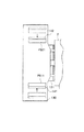
《Detailed explanation of stack stack tray and sample tray》
Next, the
[0069]
The
[0070]
The
[0071]
That is, a pair of
[0072]
On the other hand, the rotation output of the stepping motor M200 is transmitted to the
[0073]
The
[0074]
In addition, the
[0075]
Next, each sensor arrangement (details are shown in FIG. 9) for controlling the raising and lowering positions of the
[0076]
The sensor S202 is a sensor for detecting the stacking area of the
[0077]
The sensor S203b is a sensor for detecting that a predetermined number of sheets P are discharged from the second
[0078]
The sensor S203c is a sensor for detecting that a predetermined number of sheets P are discharged from the
[0079]
The sensor S203d is a sensor for limiting the height of the stacking amount when the
[0080]
The sensor S203e is a sensor that sets the lower limit position of the
[0081]
The
[0082]
Of these sensors, only the sheet surface detection sensors S204 and S205 are set to a light transmission type that detects the presence or absence of light by transmitting light from one side edge of the sheet P to the other side edge. Here, as the sheet surface detection method, the state in which the
[0083]
<Detailed description of punch unit>
Next, the
[0084]
The
[0085]
The punching means 60 includes a predetermined number of punches, in this case, a pair of left and
[0086]
In this state, after detecting the trailing edge of the sheet P to which the sheet detection sensor 31 (see FIGS. 1, 13, and 14) is introduced, the punching
[0087]
On the other hand, a
[0088]
For this reason, the punching means 60 is moved in the directions of arrows D and E (width direction of the sheet P) perpendicular to the conveyance direction A of the sheet P by driving of the punching means moving motor, and the punching means initial position detection sensor is accompanied with the movement. 71, the punching means initial
[0089]
In addition, the lateral
[0090]
For this reason, as in the case of the punching means 60, the lateral registration detection means 80 moves in the directions of arrows D and E (the width direction of the sheet P) perpendicular to the conveyance direction A of the sheet P by driving the lateral registration movement motor. In accordance with this movement, the lateral regi- nal
[0091]
Here, when detecting the side edge portion of the sheet, after the
[0092]
In other words, this makes it possible to align the punching position with the side end portion of the sheet.
[0093]
<< Explanation of the overall operation of the sheet processing apparatus >>
Next, the operation (operation) of each main part of the sheet processing apparatus will be described.
[0094]
<Explanation of matching operation>
FIG. 15 is an explanatory plan view showing an aspect of preparation for alignment operation by each alignment member of the sheet bundle. FIG. 16 is an explanatory plan view showing the alignment operation state of the first part (odd number part), and FIG. 17 is an explanatory plan view showing the alignment operation state of the second part (even number part). FIG. 18 is an explanatory side view showing the sorting and stacking state of the sheet bundle, and FIG. 19 is a partial explanatory view showing an example of misalignment according to an example.
[0095]
When the first image-formed sheet is discharged onto the
[0096]
As described above, the sheet P discharged onto the
[0097]
Thereafter, in order to prepare for the next sheet P to be discharged, one
[0098]
The above operations are continued until the final sheet P to be discharged, and when the discharge and alignment of the first sheet bundle Pa corresponding to the completion are completed in this way, each processing and bundle discharge described later are performed, and this is the stack tray. 200.
[0099]
Subsequently, the sheet P corresponding to the next second set is discharged onto the
[0100]
Thereafter, by stacking the sheets on the
[0101]
The offset distance L is changed between the sort mode and the staple sort mode. That is, for example, in the staple sort mode, the amount L1 is set so as to prevent the adjacent needles from overlapping after loading, and in the sort mode, the amount L2 is set so as to reliably identify the bundle. Further, in this case, the speed of the staple sort mode can be increased by setting the relationship between the respective amounts so that L1 <L2.
[0102]
Further, as described above, by setting the respective alignment standby positions PS11 and PS21 for the
[0103]
<Description of staple operation>
20 to 22 are explanatory plan views showing staple states at different positions (center position, right corner position, and left corner position), respectively.
[0104]
In the stapling mode, the
[0105]
Also in this case, the
[0106]
Further, the
[0107]
<Explanation of bundle ejection operation in staple mode>
In the single staple sort mode, the stapling operation is started when the alignment operation is completed. Then, the
[0108]
The lowering start timing of the
[0109]
After a predetermined time elapses from when the bundle discharge
[0110]
At this time, the discharge speed of the sheet bundle Pa is controlled as follows. That is, the sheet is conveyed at a high speed after the bundle conveyance is started, but is decelerated before the trailing end of the sheet bundle Pa passes through the
[0111]
Further, during the bundle discharge, the retracting
[0112]
On the other hand, in the two-point staple sort mode, the first staple operation by the
[0113]
Incidentally, FIG. 35 shows a timing chart of the bundle discharging operation in the single-sheet few-sheet staple mode, FIG. 36 shows a timing chart of the bundle discharging operation in the one-sheet multiple-sheet staple mode, and FIG. A timing chart of the bundle discharging operation in the two-place staple mode is shown, respectively, and FIG. 38 shows a flowchart of the bundle discharging operation in the staple mode.
[0114]
《Explanation of stack tray and sample tray operation》
Next, operations of the
[0115]
Prior to the start of operation, each of these
[0116]
The sheet bundle Pa aligned in the
[0117]
When the bundle discharging operation is completed, the
[0118]
The
[0119]
That is, in this state, the
[0120]
Further, when the stack discharge is continued and the tray surface of the
[0121]
In this alarm state, any one of the sheet detection sensors S206a and S206b provided in the
[0122]
That is, for example, when the sheet detection sensor S206a on the
[0123]
When the sheet detection sensor S206b on the
[0124]
《Explanation of sheet flow in non-sort mode》
Next, the flow of sheets in the non-sort mode will be described.
[0125]
FIG. 23 is an operation explanatory diagram showing the flow of sheets in the non-sort mode.
[0126]
When the user sets the paper discharge mode of the
[0127]
In this case, the
[0128]
<Description of sheet flow in staple sort mode>
Next, the flow of sheets in the staple sort mode will be described.
[0129]
24 and 28 are operation explanatory diagrams sequentially showing the flow of sheets in the staple sort mode, and FIGS. 29 to 31 (a) and (b) sequentially show the alignment operation of the sheets. It is operation | movement explanatory drawing.
[0130]
When the user sets the paper discharge mode of the
[0131]
In this case, the
[0132]
Subsequently, the sheet P thus discharged onto the
[0133]
In this state, when the trailing edge of the sheet P is abutted against the trailing
[0134]
On the other hand, the sheet P1 discharged from the
[0135]
Further, when the leading edge of the succeeding sheet P2 advances a predetermined distance from the
[0136]
Subsequently, as shown in FIG. 28, when the leading end of the third sheet P3 advances a predetermined distance from the
[0137]
At this point in time, the bundle discharging operation of the previous sheet bundle Pa is completed or almost finished. Here, as shown in FIG. 29, the
[0138]
In addition, as shown in FIG. 30, when the trailing edge of each of the three sheets P passes through the first
[0139]
Subsequently, the fourth and subsequent sheets P are discharged onto the
[0140]
Here, when transporting the plurality of sheets P, the sheets P are offset along the transport direction as shown in FIG. 31 (b). That is, the sheet P2 is offset to the opposite side to the
[0141]
<Description of sheet flow in sort mode>
Next, the flow of sheets in the sort mode will be described.
[0142]
32 and 33 are operation explanatory diagrams sequentially showing the flow of sheets in the sort mode.
[0143]
When the user sets the paper discharge mode of the
[0144]
<Explanation of sheet interrupt mode>
Next, the operation in the interrupt mode of the seat will be described.
[0145]
When the interrupt mode is selected by the user, as in the non-sort mode, the sheets P are sequentially guided to the
[0146]
When the specified number of sheets P are discharged, the
[0147]
The above operation is repeated each time a specified number of sheets P are discharged from the second pair of
[0148]
That is, in this state, the
[0149]
Next, when the sheet P on the
[0150]
<Description of punch mode>
Next, the punch mode will be described based on the flowchart of FIG.
[0151]
First, when the apparatus is turned on (ST-1), the punching means 60 is moved in the direction of arrow E in FIG. Thereafter, when the punching means initial
[0152]
Next, when the lateral registration movement motor moves the
[0153]
Here, when the punch mode is designated by the user and the start signal is input (ST-4), the punching means 60 is moved and set to a position corresponding to the selected sheet size (ST-5). ).
[0154]
In this state, when the sheet P on which the image is formed (ST-6) by the
[0155]
When the leading edge of the sheet P conveyed by the
[0156]
Subsequently, when the
[0157]
Subsequent operations are the same as those in the non-sort mode, the sort mode, and the staple sort mode.
[0158]
<< Description of Control Circuit in Present Embodiment >>
Next, the configuration and operation of the control circuit applied to this embodiment will be described.
[0159]
FIG. 39 is a block diagram showing a circuit configuration of the control device of the present embodiment.
[0160]
In the present embodiment, the control circuit is configured around a microprocessor (CPU) 401. The
[0161]
Here, the sort / non-sort switching solenoid SL1 is driven by the driver D1, and similarly, the buffer solenoid SL2 is driven by the driver D2.
[0162]
The inlet motor M1 (DC brushless motor) is driven and controlled by a motor-integrated driver, and receives drive signals from the
[0163]
The puncher rotation drive motor 66 (stepping motor) is driven with a constant current by a stepping motor driver D6. The puncher shift drive motor M300 (stepping motor) is controlled to be driven at a constant current by a stepping motor driver D7.
[0164]
The puncher waste conveyance motor M301 (DC brush motor) is driven and controlled by a driver D8, and an ON / OFF signal is input from the
[0165]
The paddle positioning solenoid SL3 is driven by a driver D1O. The reference wall moving motor M141 (stepping motor) is controlled by constant current drive by the stepping motor driver D11. Similarly, the alignment wall moving motor M142 (stepping motor) is controlled by constant current drive by the stepping motor driver D12.
[0166]
The paddle motor M160 (DC brushless motor) is driven and controlled by a motor-integrated driver, and receives driving signals from the
[0167]
The bundle discharging motor M180 (DC brush motor) is driven and controlled by a driver D15 and a controller C15. The controller C15 receives a reference clock from the
[0168]
The stapler moving motor M100 (stepping motor) is controlled to be driven by a constant current by a stepping motor driver D17, and the stapler motor M101 (DC brush motor) is controlled to be driven by a driver D18 and a controller C18. A reference clock, which is a reference for the motor rotation speed, and driving signals such as ON / OFF are input.
[0169]
The sample tray shift motor M201 (stepping motor) is controlled by constant current drive by a stepping motor driver D19. Similarly, the stack tray shift motor M200 (stepping motor) is controlled by constant current drive by a stepping motor driver D20.
[0170]
All of the drivers D1 to D20 are connected to the input / output ports of the
[0171]
An
[0172]
The various sensors are the following sensors.
[0173]
That is, a puncher HP sensor S106, a puncher rotation HP sensor S108, a puncher debris full sensor S110, a reference wall HP sensor S111, an alignment wall HP sensor S112, a bundle discharge swing close detection sensor S113, a shutter HP sensor S114, a bundle discharge swing Motion guide HP detection sensor S115, bundle discharge swing motor clock detection sensor S116, bundle discharge motor clock detection sensor S117, retracted tray down detection sensor S118, bundle discharge completion sensor S119, stapler HP sensor S120, stapler home sensor S121, stapler needle A sensorless sensor S122, a stapler cartridge sensor S123, a stapler self-priming sensor S124, and a door switch operation detection sensor S128.
[0174]
The stack tray idle detection sensor S201a, stack tray upper position detection sensor S202a, stack tray lower position detection sensor S203d, stack tray lower limit detection sensor S203e, stack tray paper surface detection sensor S205, and stack tray paper presence / absence detection sensor S206. Sample tray idle detection sensor S201b, sample tray upper position detection sensor S202b, sample tray upper limit detection sensor S203a, sample tray lower position detection sensor S203b, sample tray lower limit detection sensor S203c, sample tray paper surface detection sensor S204, Each of the sensors of the sample tray paper presence / absence detection sensor S206b.
[0175]
【The invention's effect】
As described above in detail according to the embodiment, according to the present invention, the first stacking tray unit that receives discharged sheets, the aligning unit that aligns the sheet bundle on the first stacking tray unit, and the alignment A sheet processing apparatus including a binding unit that binds the sheet bundle aligned by the unit, and a transfer unit that transfers the sheet bundle bound by the binding unit onto the second stacking tray unit, and an image forming apparatus including the sheet processing apparatus. In the configuration, since the transfer operation control unit controls the start of the transfer operation of the transfer unit during the alignment operation by the alignment unit or the binding operation by the binding unit, the bundle processing speed of the sheet bundle can be improved. In addition, there is an advantage that stability of sheet bundle bundle discharge is obtained, and as a result, whether the required sheet processing performance of the sheet processing apparatus itself is effective. It is possible to significantly increase.
[0176]
On the other hand, in the apparatus configuration, the counting means for counting the number of sheets received on the first stacking tray means, and the timing control means for changing the operation start timing by the transfer operation control means in accordance with the counting result of the counting means. And a transfer means, a conveying means for conveying the sheet bundle on the first stacking tray means onto the second stacking tray means, an abutting operation means for bringing the conveying means into contact with the sheet bundle, and abutting The contact activation control means for controlling the time from the end of the contact operation by the actuating means to the start time of the transfer by the transport means, and the structure of the contact speed control means for controlling the moving speed of the contact actuating means. When each is provided, the operation of the sheet processing apparatus can be promoted more effectively.
[0177]
In addition, according to the present invention, since the start of the swinging operation and, in turn, the start of the bundle discharging operation is controlled in accordance with the sheet stacking amount on the processing tray, the stability of discharging the bundle of sheet bundles is controlled. In addition, it is possible to control the start timing of the swinging operation corresponding to the binding mode, which helps to improve the quality of the binding process, and further enables the speed control of the swinging operation. The swinging operation can be completed in a predetermined time, so that the reliability of timing control is improved and the bundle processing time can be shortened.
[Brief description of the drawings]
FIG. 1 is an overall cross-sectional view schematically showing a schematic configuration of a sheet processing apparatus to which an embodiment of the present invention is applied.
FIG. 2 is a cross-sectional view of a stapler and a processing tray corresponding to a main cross section of the staple unit.
FIG. 3 is a plan view of a stapler moving mechanism corresponding to the direction of arrow a in FIG. 2;
4 is a rear view of the stapler corresponding to the direction of arrow b in FIG. 2;
FIG. 5 is a cross-sectional view of a swing guide and a processing tray corresponding to the main cross section of the aligning means.
6 is a plan view of a processing tray and an alignment wall moving mechanism corresponding to a direction indicated by an arrow c in FIG. 5;
7 is a plan view of an appearing tray corresponding to a direction indicated by an arrow d in FIG.
FIG. 8 is a plan view of the moving mechanism portion of the stack tray.
FIG. 9 is a sensor layout diagram around the stack tray and the sample tray.
FIG. 10 is a side view showing the configuration of the punch unit.
FIG. 11 is a side view showing an operating state of the punch unit.
FIG. 12 is a plan view showing the punch unit portion.
FIG. 13 is an explanatory plan view showing a state of detection of the leading edge of the sheet in the punch unit.
FIG. 14 is an explanatory plan view showing a detection state of the trailing edge of the sheet in the punch unit.
FIG. 15 is an explanatory plan view showing an aspect of preparation for alignment operation by each alignment member in the non-sort mode.
FIG. 16 is an explanatory plan view showing the alignment operation state of the first part (odd part) by each alignment member in the staple sort mode.
FIG. 17 is an explanatory plan view showing an alignment operation state of the second part (even number part) by each alignment member in the staple sort mode.
FIG. 18 is an explanatory side view showing a stacked state by sorting sheet bundles in the sort mode.
FIG. 19 is a partial explanatory view showing an aspect of sheet misalignment in the sort mode.
FIG. 20 is an explanatory plan view showing a staple state at the center position in the staple sort mode.
FIG. 21 is an explanatory plan view showing a staple state at the right corner position in the staple sort mode.
FIG. 22 is an explanatory plan view showing a staple state at the left corner position in the staple sort mode.
FIG. 23 is an operation explanatory view showing the flow of sheets in the non-sort mode.
FIG. 24 is an operation explanatory diagram showing the flow of sheets in the staple sort mode.
FIG. 25 is an operation explanatory diagram showing the flow of sheets in the staple sort mode.
FIG. 26 is an operation explanatory diagram showing the flow of sheets in the staple sort mode.
FIG. 27 is an operation explanatory diagram showing the flow of sheets in the staple sort mode.
FIG. 28 is an operation explanatory diagram showing the flow of sheets in the staple sort mode.
FIG. 29 is an operation explanatory view showing a first stage of the sheet alignment operation.
FIG. 30 is an operation explanatory diagram illustrating a second stage of the sheet alignment operation.
FIG. 31 is an operation explanatory diagram sequentially illustrating the sheet alignment operation.
FIG. 32 is an operation explanatory diagram showing the flow of sheets in the sort mode.
FIG. 33 is an operation explanatory diagram showing the flow of sheets in the sort mode.
FIG. 34 is a flowchart of the punching operation in the same punch mode.
FIG. 35 is a timing chart showing the timing of a bundle discharging operation in the one-piece small number staple mode.
FIG. 36 is a timing chart showing the timing of the bundle discharging operation in the one-multiple staple mode.
FIG. 37 is a timing chart showing the timing of the bundle discharging operation in the two-place staple mode.
FIG. 38 is a flowchart of a bundle discharging operation in the staple mode.
FIG. 39 is a block diagram showing a circuit configuration of a control device according to the present embodiment;
FIG. 40 is an overall cross-sectional view schematically showing a schematic configuration of an example of an image forming apparatus (copying apparatus) system including a sheet processing apparatus according to the present embodiment;
[Explanation of symbols]
1 Sheet processing equipment (finisher)
2 Inlet roller pair
3 First conveying roller pair
5 Large diameter roller (buffer roller)
6 Second transport roller pair
7 First discharge roller pair
9 Second discharge roller pair
10 Second switching flapper
11 First switching flapper
12, 13, 14 rollers
21 Non-sort path
22 Sort path
23 Buffer path
31 Entrance side sheet detection sensor
32, 33 Sheet detection sensor in path
40 bundle loading guide
50 punch unit
52 Drilling means initial position defining portion
60 Drilling means
61 Punch material
61a Punch protruding piece
62 Die parts
62b Die hole
63 Casing
63a rack gear
63b Horizontal Residual Initial Positioning Section
64, 65 interlocking gear
66 Punching motor
67 Guide rail
68 Guide Roller
69 Support shaft
70 pinion gear
71 Drilling means initial position detection sensor
71a Light receiver
80 Side register detection means
81 Side register detection sensor
81a Light receiver
82 Sensor arm
82a rack gear
83 Pinion gear
84 Lateral initial position detection sensor
84a Light receiver
100 Staple unit
101 Stapler (binding means)
102 Holder
103 Moving platform
104,1051 stud shafts
106,107 Rolling roller
106a flange
106b Pinion gear
106c belt pulley
108 fixed base
108a, 108b, 108c series of hole-shaped guide rails
109 Support roller
110 rack gear
111 Stud shaft
112 Stopper roll
113 Staple stopper
129 Processing tray unit
130 Intermediate tray (processing tray, first stacking tray)
130a, 130b1 set of guide grooves
131 Rear end stopper
131a Abutting support surface
131b pivot pin
131c pin
132 Main link
132a Cam surface
132b pin
133 Link
134 axes
135 tension spring
136 butt plate
131 Rear end stopper
131 Rear end stopper
131 Rear end stopper
140 Alignment means
141, 1421 sets of alignment members
141a, 142a alignment surface
141b, 142b rack gear section
141, 1421 sets of alignment members
143,144 pinion gear
150 Swing guide
151 Support shaft
152 Rotating cam
160 retractable paddle
161 Drive shaft
170 Haunting tray
171 Support frame
172 Guide rail
173 Rotating cam roller
174 axis of rotation
175 Bottom groove
180 Bundle discharge roller pair
180a Lower discharge roller
180b Upper discharge roller
200 stack tray (second loading tray)
201 Sample tray
202, 203 tray base plate
204, 205 mounting frame plate
206, 207 guide rollers
208 Restriction member
211 Timing belt
212 pulley
213 Drive shaft
214 Drive gear
215 ratchet wheel
216 Spring
217 driven shaft
218 idler gear
219 Lifting gear
250 frames
251 Rack gear member
300 Image forming device (copier)
301 Conveyor
302 discharge roller pair
310 Control device (transfer operation control means)
400 Document reader
401 Document table
402 Light source
403 lens system
500 Paper feeder
501,502 cassette
503 pedestal
504 decks
600 Image forming unit
601 Photosensitive drum
602 Primary charger
603 Exposure section
604 Developer
605 Transfer charger
606 Separation charger
607 cleaner
608 Fixing device
P, P1, P2, P3 sheets
Pa sheet bundle
Claims (6)
前記第1の積載トレイ手段上のシート束を整合する整合手段と、
前記整合手段によって整合されたシート束を綴じ処理する綴じ手段と、
前記綴じ手段によって綴じられたシート束を第2の積載トレイ手段上に移送するローラ対から構成される移送手段と、
を有するシート処理装置において、
前記移送手段は、前記ローラ対の一方を前記第1の積載トレイ手段上のシート束と離間する位置から前記シート束に当接させ、シート束を前記第2の積載トレイ手段上に移送する移送動作を行い、
前記整合手段による整合動作中、または前記綴じ手段による綴じ動作中に、前記移送手段の移送動作を開始させる移送動作制御手段を備える、
ことを特徴とするシート処理装置。First stacking tray means for receiving discharged sheets;
Alignment means for aligning the sheet bundle on the first stacking tray means;
Binding means for binding the sheet bundle aligned by the alignment means;
Transfer means composed of a pair of rollers for transferring the sheet bundle bound by the binding means onto the second stacking tray means;
In a sheet processing apparatus having
The transfer means is configured to bring one of the pair of rollers into contact with the sheet bundle from a position separated from the sheet bundle on the first stacking tray means and transfer the sheet bundle onto the second stacking tray means. Perform the action
A transfer operation control means for starting the transfer operation of the transfer means during the alignment operation by the alignment means or during the binding operation by the binding means;
A sheet processing apparatus.
前記揺動部材を揺動させて前記ローラ対の一方を前記シート束に当接させる当接作動手段と、
前記当接作動手段による当接動作終了時点から、前記搬送手段による搬送開始時点までの時間を制御する当接起動制御手段と、を備える、
ことを特徴とする請求項1ないし3の何れか1項に記載のシート処理装置。A swing member that supports one of the pair of rollers ;
A contact actuating means for swinging the swinging member so that one of the roller pair contacts the sheet bundle;
Contact activation control means for controlling a time from a contact operation end time by the contact operation means to a transfer start time by the transfer means,
The sheet processing apparatus according to claim 1, wherein the sheet processing apparatus is a sheet processing apparatus.
前記画像読取り手段によって読み取られた画像をシートの対象面に転写する画像転写手段と、
前記画像転写手段によって転写された画像を定着処理する画像定着手段と、を有して、
シートの対象面に画像形成を行う画像形成装置において、
前記対象面に画像形成されたシートを排出するための前記請求項1ないし5の何れか1項に記載のシート処理装置、を備える、
ことを特徴とする画像形成装置。Image reading means for reading an image on a document surface;
Image transfer means for transferring the image read by the image reading means to the target surface of the sheet;
Image fixing means for fixing the image transferred by the image transfer means,
In an image forming apparatus that forms an image on a target surface of a sheet,
The sheet processing apparatus according to any one of claims 1 to 5, for discharging a sheet having an image formed on the target surface.
An image forming apparatus.
Priority Applications (1)
| Application Number | Priority Date | Filing Date | Title |
|---|---|---|---|
| JP13900998A JP4046848B2 (en) | 1998-05-20 | 1998-05-20 | Sheet processing apparatus and image forming apparatus having the same |
Applications Claiming Priority (1)
| Application Number | Priority Date | Filing Date | Title |
|---|---|---|---|
| JP13900998A JP4046848B2 (en) | 1998-05-20 | 1998-05-20 | Sheet processing apparatus and image forming apparatus having the same |
Publications (3)
| Publication Number | Publication Date |
|---|---|
| JPH11334973A JPH11334973A (en) | 1999-12-07 |
| JPH11334973A5 JPH11334973A5 (en) | 2007-06-14 |
| JP4046848B2 true JP4046848B2 (en) | 2008-02-13 |
Family
ID=15235357
Family Applications (1)
| Application Number | Title | Priority Date | Filing Date |
|---|---|---|---|
| JP13900998A Expired - Fee Related JP4046848B2 (en) | 1998-05-20 | 1998-05-20 | Sheet processing apparatus and image forming apparatus having the same |
Country Status (1)
| Country | Link |
|---|---|
| JP (1) | JP4046848B2 (en) |
Families Citing this family (3)
| Publication number | Priority date | Publication date | Assignee | Title |
|---|---|---|---|---|
| JP4719637B2 (en) * | 2005-08-11 | 2011-07-06 | キヤノン株式会社 | Sheet processing apparatus and image forming apparatus |
| JP5995647B2 (en) * | 2012-10-12 | 2016-09-21 | ニスカ株式会社 | Sheet storage device and image forming system using the same |
| JP6704619B2 (en) * | 2015-12-24 | 2020-06-03 | キヤノンファインテックニスカ株式会社 | Sheet ejection device, image forming system and sheet post-processing device |
-
1998
- 1998-05-20 JP JP13900998A patent/JP4046848B2/en not_active Expired - Fee Related
Also Published As
| Publication number | Publication date |
|---|---|
| JPH11334973A (en) | 1999-12-07 |
Similar Documents
| Publication | Publication Date | Title |
|---|---|---|
| JP3526226B2 (en) | Sheet processing apparatus and image forming apparatus having the same | |
| JP3728178B2 (en) | Sheet processing apparatus and image forming apparatus | |
| JPH11147648A (en) | Sheet processing apparatus and image forming apparatus having the same | |
| JP3363725B2 (en) | Sheet punching device, sheet processing device, and image forming device | |
| JPH11147641A (en) | Sheet processing apparatus and image forming apparatus having the same | |
| JPH10279170A (en) | Sheet punching device, sheet post-processing device, and image forming device | |
| JP3051685B2 (en) | Sheet processing apparatus and image forming apparatus having the same | |
| JP3728039B2 (en) | Sheet processing apparatus and image forming apparatus having the same | |
| JP3542474B2 (en) | Sheet processing apparatus and image forming apparatus having the same | |
| JP3799124B2 (en) | Sheet post-processing apparatus and image forming apparatus | |
| JP4208370B2 (en) | Sheet processing apparatus and image forming apparatus having the same | |
| JP3352345B2 (en) | Sheet processing apparatus and image forming apparatus having the same | |
| JP2000169036A (en) | Sheet processing apparatus and image forming apparatus having the same | |
| JP4046848B2 (en) | Sheet processing apparatus and image forming apparatus having the same | |
| JP3193894B2 (en) | Sheet processing apparatus and image forming apparatus having the same | |
| JPH11147654A (en) | Sheet processing apparatus and image forming apparatus having the same | |
| JP3453502B2 (en) | Sheet processing apparatus and image forming apparatus having the same | |
| JP3416691B2 (en) | Sheet processing apparatus and image forming apparatus having the same | |
| JP3296763B2 (en) | Sheet processing apparatus and image forming apparatus having the same | |
| JP2000143056A (en) | Sheet processing apparatus and image forming apparatus having the same | |
| JP4474471B2 (en) | Sheet processing device | |
| JP4136276B2 (en) | Sheet processing apparatus and image forming apparatus | |
| JP3740302B2 (en) | Sheet processing apparatus and image forming apparatus having the same | |
| JP4124889B2 (en) | Image forming apparatus | |
| JPH11320494A (en) | Sheet punching apparatus, sheet processing apparatus having the same, and image forming apparatus |
Legal Events
| Date | Code | Title | Description |
|---|---|---|---|
| A621 | Written request for application examination |
Free format text: JAPANESE INTERMEDIATE CODE: A621 Effective date: 20050519 |
|
| A521 | Written amendment |
Free format text: JAPANESE INTERMEDIATE CODE: A523 Effective date: 20070424 |
|
| A977 | Report on retrieval |
Free format text: JAPANESE INTERMEDIATE CODE: A971007 Effective date: 20070521 |
|
| A131 | Notification of reasons for refusal |
Free format text: JAPANESE INTERMEDIATE CODE: A131 Effective date: 20070529 |
|
| A521 | Written amendment |
Free format text: JAPANESE INTERMEDIATE CODE: A523 Effective date: 20070730 |
|
| TRDD | Decision of grant or rejection written | ||
| A01 | Written decision to grant a patent or to grant a registration (utility model) |
Free format text: JAPANESE INTERMEDIATE CODE: A01 Effective date: 20071120 |
|
| A61 | First payment of annual fees (during grant procedure) |
Free format text: JAPANESE INTERMEDIATE CODE: A61 Effective date: 20071121 |
|
| FPAY | Renewal fee payment (event date is renewal date of database) |
Free format text: PAYMENT UNTIL: 20101130 Year of fee payment: 3 |
|
| R150 | Certificate of patent or registration of utility model |
Free format text: JAPANESE INTERMEDIATE CODE: R150 |
|
| FPAY | Renewal fee payment (event date is renewal date of database) |
Free format text: PAYMENT UNTIL: 20101130 Year of fee payment: 3 |
|
| FPAY | Renewal fee payment (event date is renewal date of database) |
Free format text: PAYMENT UNTIL: 20111130 Year of fee payment: 4 |
|
| FPAY | Renewal fee payment (event date is renewal date of database) |
Free format text: PAYMENT UNTIL: 20121130 Year of fee payment: 5 |
|
| FPAY | Renewal fee payment (event date is renewal date of database) |
Free format text: PAYMENT UNTIL: 20131130 Year of fee payment: 6 |
|
| LAPS | Cancellation because of no payment of annual fees |