JP4124889B2 - Image forming apparatus - Google Patents
Image forming apparatus Download PDFInfo
- Publication number
- JP4124889B2 JP4124889B2 JP32091698A JP32091698A JP4124889B2 JP 4124889 B2 JP4124889 B2 JP 4124889B2 JP 32091698 A JP32091698 A JP 32091698A JP 32091698 A JP32091698 A JP 32091698A JP 4124889 B2 JP4124889 B2 JP 4124889B2
- Authority
- JP
- Japan
- Prior art keywords
- sheet
- bundle
- unit
- processing
- stacking
- Prior art date
- Legal status (The legal status is an assumption and is not a legal conclusion. Google has not performed a legal analysis and makes no representation as to the accuracy of the status listed.)
- Expired - Lifetime
Links
Images


Description
【0001】
【発明の属する技術分野】
本発明は、画像形成装置に係り、詳細には、例えば、排出されるシートを処理するものに関する。
【0002】
【従来の技術】
従来、画像形成されたシートを整合し、針綴じ等のシート処理(後処理ともいう)を行うための第1のシート積載部(以下処理トレイ)と、シート束を束毎に受け取って積載する第2のシート積載部(以下スタックトレイ)と、を組み合わせた装置については、例えば(特開平2−144370号公報)に開示された技術を含めて、既に多数提案され、実施されている。その中で、スタックトレイ上での束識別を可能にするため、又は、針綴じ部の積載高さが増大し、シート束の上面が均一面にならなくなることを防止するために、シート束を所定量交互にずらして積載するオフセット積載も考案されている。
【0003】
【発明が解決しようとする課題】
しかしながら、前記オフセット積載の実施の形態として、スタックトレイ自身がシフトするタイプにおいては、スタックトレイ上での積載容量が少数であれば有効であったが、近年の大容量化、多数枚処理においては、スタックトレイをシフトするための負荷が増大し、また、シート束の積載状態を維持させるためにも、束のくずれや、落下等の視点で、更なる改良が望まれている。
【0004】
また、処理トレイ上でのシート束の整合位置を、1束毎に交互に異ならせ、その位置からシート束を束排出することにより、スタックトレイ上でのオフセットを可能にするタイプも考案されているが、シート束の整合位置が異なるため、シート処理手段(後処理手段)を、シート束のオフセット量に合わせて移動させる必要があり、後処理手段部における構成が複雑になる。
【0005】
また、シート束の整合位置が異なることにより、その他の機構による整合条件が異なってしまい(例えば、シートの排出位置に対する整合時の、シート移動量や、シート整合方向、その他の負荷条件)、適正なシート整合が得られない虞れがある。
【0006】
本発明は、スタックトレイ上でのシート束のオフセット積載を可能にしつつ、シートの整合不良の回避構成の簡易化を図った画像形成装置を提供することを目的とするものである。
【0007】
【課題を解決するための手段】
本発明は、シートに画像を形成する画像形成手段と、前記画像形成手段により画像形成されたシートを排出する排出手段と、前記排出手段から排出されるシートを積載する第1の積載手段と、前記第1の積載手段上に積載されたシート束を搬送する束搬送手段と、前記束搬送手段により束搬送されるシート束を積載する第2の積載手段と、前記第1の積載手段に積載されたシート束の異なる処理位置に、所定の後処理を行うことが可能なシート束処理手段と、シートサイズ及び前記処理位置に応じて、前記第1の積載手段上の、前記束搬送手段によるシート束の搬送方向と交差する方向の異なる整合位置にシートを整合する整合手段と、前記シート束処理手段による前記後処理後、前記搬送方向と交差する方向に前記第1の積載手段に積載されたシート束をシフトする束シフト手段と、前記束搬送手段、前記束シフト手段及び前記シート束処理手段の動作を制御する制御手段と、を備え、前記整合手段は、前記搬送方向と交差する方向において第1のシート幅を有するサイズのシートの場合、一束ごとに前記整合位置を前記搬送方向と交差する方向に変えてシートを整合し、前記第1のシート幅よりも小さい第2のシート幅を有するサイズのシートの場合、束ごとに前記整合位置を変えることなくシートを整合し、前記制御手段は、前記第1の積載手段上に積載されたシートのサイズ及び処理位置に応じた前記整合手段による整合動作後に前記シート束処理手段による前記後処理を実行させ、さらに、前記第2のシート幅を有するサイズのシートの場合は前記後処理実行後、前記シフト手段により一束おきにシフト動作を実行させた後、前記束搬送手段によりシート束を前記第2の積載手段へ搬送させ、前記第1のシート幅を有するサイズのシートの場合は前記後処理実行後、前記シフト手段によるシフト動作を行うことなく、前記束搬送手段によりシート束を前記第2の積載手段へ搬送させることを特徴とする。
【0011】
また本発明は、前記シート束処理手段は、シート束綴じ手段であることを特徴とする。
【0012】
また本発明は、前記束シフト手段は、整合手段を兼ねていることを特徴とする。また本発明は、前記制御手段は、前記第1の積載手段上のシートのシートサイズ、前記シート束処理手段による処理位置に応じて、前記束シフト手段によるシート束のシフト方向、若しくは移動量を選択することを特徴とする。
【0013】
[作用]
以上構成に基づき、第1の積載手段に排出・積載されたシート束は、整合手段による整合、束シフト手段による束シフト、シート束処理手段によるシート処理、等が行われ、その作用を次に示す。
【0014】
(a)、第1の積載トレイにおけるシート束の整合位置は同じにし、シート束の整合終了後、整合方向へシート束を束シフトした後、第2の積載トレイへ束搬送する束と、束シフトせずに束搬送する束と、を交互に行うことにより、第2の積載手段へのオフセット積載を可能にしつつ、シート束の整合性の悪化も防止される。
【0015】
(b)、(a)と同様に、シート束の整合終了後、針綴じ等の処理動作を行った後に、束シフトする束と、束シフトしない束と、を交互に束搬送し、スタックトレイ上にオフセット積載する。
【0016】
(c)、(b)と同様、若しくは、束シフト後に処理動作を行った束と、束シフトせずに、処理動作を行った束と、を交互に束搬送し、スタックトレイ上にオフセット積載する。
【0017】
(d)、整合手段が束シフト手段を兼ねることにより、より安価な装置の構成を提供できる。
【0018】
【発明の実施の形態】
以下、本発明に係るシート処理装置及びこれを備える画像形成装置の好ましい実施形態例につき、図1ないし図26を参照して詳細に説明する。
【0019】
先ず最初に、本発明に係る画像形成装置、ここでは、シート処理装置を備える画像形成装置について説明する。
【0020】
図26に基づいて、原稿搬送装置、シート処理装置を備える画像形成装置の構成を説明する。
【0021】
原稿搬送装置(シート材搬送装置)であるADF2は、上方に原稿トレイ4を有し、その下方には、駆動ローラ36及び他方のターンローラ37に巻回された幅広ベルトが配置されている。原稿トレイ4上の原稿(シート材)Pは、順次その最上紙から分離手段により分離・給送され、複写機本体の読取位置(画像読み取り部)であるプラテンガラス(プラテン)3に搬送される。
【0022】
幅広ベルトは、プラテン3上に正逆回転自在に当接していて、上記原稿トレイ4から搬送されたシート材原稿Pを、プラテン3の上の所定位置に載置したり、プラテン3上のシート材原稿Pを排紙トレイ10上に搬出する。なお、原稿Pは、上から順に1ページ(2ページ)、3ページ(4ページ)・‥の順番で原稿トレイ4に載置される。
【0023】
画像形成装置本体としての複写機本体1’は、画像入力部200’(以下リーダ部という)と画像出力部300(以下プリンタ部という)により構成されている。
【0024】
リーダ部200’は、原稿Pに記録された画像情報を光学的に読み取り、光電変換して画像データとして入力するものであり、プラテン3と、ランプ202、ミラー203とを有するスキャナーユニット204と、ミラー203a、レンズ205a、イメージセンサ205b等とを有している。プリンタ部300は、周知の静電潜像画像形成を用いた画像形成手段である。
【0025】
次に、画像出力部であるプリンター部300の説明をする。
【0026】
800は上段カセットで、カセット内のシート材は分離爪と給送ローラ801の作用によって1枚ずつ分離給送されてレジストローラ806に導かれる。802は下段カセットで、カセット内のシート材は分離爪と給送ローラ803の作用によって1枚ずつ分離給送されてレジストローラ806に導かれる。804は、手差しガイドで、1枚ずつシート材がローラ805を介してレジストローラ806に導かれる。808はシート材積載装置(デッキタイプ)で、モータ等により昇降する中板808aを備え、中板上のシート材は、給送ローラ809と分離爪の作用により1枚ずつ分離給送されて搬送ローラ810に導かれる。
【0027】
812は感光ドラム、814は現像器、815は転写帯電器、816は分離帯電器であり、画像形成部を構成する。
【0028】
817は画像形成されたシート材を搬送する搬送ベルト、818は定着装置、819は搬送ローラ、820はフラッパである。画像形成されたシート材は、フラッパ820によって本体排出ローラ(本体排出手段)821に導かれ、下流側のシート処理装置に排出される。
【0029】
プラテン上に配置された1枚の原稿に対して、設定されたコピー枚数に応じて、感光ドラム812上に像が形成され、コピー枚数分のシート材がカセット800、802、デッキ808のいずれかから、画像が感光ドラムに形成される毎に給送される。感光ドラム812上の像とシート材の位置合わせは、レジストローラ806によって行われる。
【0030】
必要枚数のコピーが形成されると、その原稿はプラテン上から排出され、次の原稿がプラテン上に位置決めされる。以下、同様である。
【0031】
900は中間トレイであって、シート材の両面に像を形成する場合、あるいはシート材の片面に重ねて像を形成する(多重)場合に、一度、画像が形成されたシート材を中間トレイ900へストックする。901は搬送ローラ、902は搬送ベルト、903はフラッパ、904は搬送ベルト、905は搬送ローラである。両面コピーの場合にはパス906を通って中間トレイ900にシート材を導く。
【0032】
シート材は画像面が上を向いている。多重コピーの場合はパス907を通って中間トレイ900にシート材を導く。シート材は画像面が下を向いている。
【0033】
中間トレイ900に積載されたシート材は、補助ローラ909、910、正逆転分離ローラ対911の作用によって下方から1枚ずつ分離されて再給送される。再給送されたシート材は搬送ローラ913、914、915及びローラ810、レジストローラ806を介して画像形成部へ導かれる。画像形成後は、前述と同様に排出される。
【0034】
プラテン上に配置された1枚の原稿に対して設定されたコピー枚数に応じて、先ず片面のコピーがなされ、それらは中間トレイ900に積載される。その後、プラテン上の原稿の表裏を反転させて再びプラテン上に導き、この像をコピー枚数分だけ読み取る。読み取られた像は読み取り毎に中間トレイ900から再給送されるシート材に形成される。一方、原稿を原稿自動給送装置によって1循する毎にコピーを1組だけ作成する方法もある。この方法によれば、複数部のコピーを作成する場合でも、ページ順の揃ったコピー群が順に得られるので、ソーターが無くても必要な部数のコピーが区分けして得られる。この方法で両面コピーをするときは、1枚の原稿の両面を続けて読み取ってシート材の表裏に続けてコピーして排出し、その後、次の原稿の両面についても同様にして、このことを何度も繰り返せば、区分けされた両面コピー群が得られる。
【0035】
複写機本体から排出される画像形成済みのシートは、本体排出ローラ(本体排出手段)302によりシート処理装置(フィニッシャともいう)1に排出される。
【0036】
複写機本体1’から搬入されたシートは、ノンソートモードの場合には、バッファローラ5、フラッパ11、ノンソートモードパス21を介し、排出ローラ9によりサンプルトレイ201に排出される。また、ソートモードの時には、バッファローラ5,フラッパ10、ソートモードパス22を介し、排出ローラ7により中間トレイとしての処理トレイ130上に一時的に積載される。処理トレイ130上のシート束は、不図示の整合部材によりシート搬送方向と交差する方向の両側部が整合され、また、必要に応じて、シート後端部がステイプラ100(101)により綴じ処理された後に、束排出ローラ対180により、スタックトレイ200上に排出される。
【0037】
続いて、本発明に係るシート処理装置について説明する。
【0038】
〈シート処理装置の全体の概要説明〉
まず、本シート処理装置の主要な各部構成について述べる。
【0039】
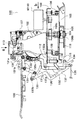
図1は、本実施の形態によるシート処理装置の概略構成を模式的に示す全体断面図である。
【0040】
この図に示すシート処理装置(以下「フィニッシャ」という)1の構成において、符号2は、前記画像形成装置300の排出ローラ対302から排出されてくるシートPを受け入れる入口ローラ対、3は、受け入れたシートPを搬送する第1搬送ローラ対であって、31は、該シートPの通過を検知する入口側でのシー卜検知センサである。また、50は、搬送されてくるシートの後端部付近に穴あけをするパンチユニットである。5は、搬送途上に配置される比較的大径のローラ(以下「バッファローラ」という)であり、外部周囲に配した各押付けコロ12,13,14でロール面にシートPを押し付けて搬送する。
【0041】
11は、第1切替えフラッパであって、ノンソートパス21とソートパス22とを選択的に切り替える。10は、第2切替えフラッパであって、ソートパス22とシートPを一時的に蓄えるためのバッファパス23との切り替えを行う。33は、ノンソートパス21内のシートPを検知するセンサ、32は、バッファパス23内のシートPを検知するセンサである。
【0042】
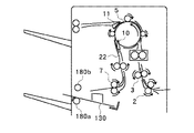
6は、ソートパス22の第2搬送ローラ対であり、129は、シートPを一時的に集積し、該集積されるシートPを整合すると共に、ステイプルユニット100(綴じ手段)のステイプラ101によってステイプル処理を行うために設けられる中間トレイ(以下「処理トレイ」という)130を含む処理トレイユニットである。処理トレイ(第1の積載トレイ)130の排出端側には、束排出ローラ対(移送手段)を構成する一方の排出ローラ、ここでは、固定側としての下排出ローラ180aが配されている。7は、ソートパス22に配されてシートPを処理トレイ(第1の積載トレイ)130上に排出させるための第1排出ローラ対、9は、ノンソートパス21に配されてシートPをサンプルトレイ201上に排出させるための第2排出ローラ対である。
【0043】
180bは、揺動ガイド150に支持されていて、該揺動ガイド150が閉じ位置にきたときに、前記下排出ローラ180aに加圧的に当接されて処理トレイ130上のシートPをスタックトレイ(第2の積載トレイ)200上に束排出するための上排出ローラである。40は、スタックトレイ200及びサンプルトレイ201上に積載されるシート束の後端(束排出方向に対して後端)縁を支持する束積載ガイドであり、ここでは、シート処理装置1の外装を兼ねている。
【0044】
〈ステイプルユニットの詳細説明〉
次に、本発明の主要部の一方を構成する前記ステイプルユニット(綴じ手段)100につき、特に、図2(主断面該当の側面図)、図3(図2のa矢視方向平面図)及び図4(図2のb矢視方向背面図)を参照して詳細に説明する。
【0045】
ステイプラ(綴じ手段)101は、ホルダ102を介して移動台103上に固定されている。
【0046】
移動台103は、処理トレイ130上に積載されるシートの後端縁に対して平行に固定された1組のスタッド軸104,105を有し、各スタッド軸104,105には、それぞれに転動コロ106,107が回動自在に組み付けられており、該各転動コロ106,107は、固定台108に対して同様に平行状態で穿設形成された一連の穴状ガイドレール108a,108b,108c内に移動可能に係合してある。
【0047】
各転動コロ106,107は、共に一連の穴状ガイドレール108a,108b,108cの穴幅よりも大径のフランジ106a,107aを有し、一方、ステイプラ101を保持する移動台103の下面側には、3ヵ所に支持コロ109が設けらており、該移動台103は、一連の穴状ガイドレール108a,108b,108cに沿って固定台108上を移動する。
【0048】
ここで、前記一連の穴状ガイドレール108a,108b,108cは、図3から明らかなように、主ガイドレール穴部分(108a)と、該部分の左端部側から分岐して平行する左端ガイドレール穴部分(108b)及び右端部側から分岐して平行する右端ガイドレール穴部分(108c)とからなる形状に形成されている。従って、該各部のレール形状のために、ステイプラ101が左方端部側に位置するときには、転動コロ106がレール穴部分108bの左端部内に、転動コロ107がレール穴部分108aの左端部内にそれぞれ移動されて、右方側に所定角度だけ傾斜された状態の右傾姿勢に維持され、また、中間部に位置するときには、各転動コロ106,107が共にレール穴部分108a内にあって非傾斜状態の平行姿勢に維持され、さらに、右方端部側に位置するときには、転動コロ107がレール穴部分108cの右端部内に、転動コロ106がレール穴部分108aの右端部内にそれぞれ移動されて、左方側に所定角度だけ傾斜された状態の左傾姿勢に維持されることになり、これらの姿勢変更の作用は不図示の作動カムによって行われる。
【0049】
なお、ステイプルユニット100には、ステイプラ101のホームポジションを検知する不図示の位置センサが設けられており、通常の場合、ステイプラ101は、左方端側のホームポジションで待機している。
【0050】
〈ステイプラ移動機構の詳細説明〉
次に、前記ステイプラ101の移動機構について詳細に説明する。
【0051】
前記移動台103の一方の転動コロ106には、フランジ106aの下方でピニオンギア106bが一体に形成され、かつ上方にベルトプーリ106cが一体化して設けられている。ピニオンギア106bは、台面上の駆動モータM100の出力プーリとベルトプーリ106cとの間に張架した駆動ベルトを介して連繋されると共に、前記レール穴に添わせて固定台108に固定したラックギア110に噛合させてあり、移動台103は、駆動モータM100の正逆回転に対応してステイプラ101と共々にシート幅方向へ移動可能にされる。
【0052】
また、移動台103の下面から下方へ伸びるスタッド軸111には、ストッパ倒しコロ112が設けられており、該ストッパ倒しコロ112は、その詳細については後述するが、前記処理トレイ130の後端ストッパ131とステイプラ101との衝接を避けるために、該後端ストッパ131を回動させる役割りを担っている。
【0053】
〈後端ストッパの詳細説明〉
次に、前記処理トレイ130上でのシートPの後端縁を突き当て支持する後端ストッパ131について詳細に説明する。
【0054】
後端ストッパ131は、処理トレイ130の積載面に対して垂直に立ち上げて形成され、シートPの後端縁を突き当て支持する突当て支持面13laを有しており、該突当て支持面13laは、処理トレイ130の下面側で枢支ピン131bを中心に矢印で示す下方側へ揺回動可能にされている。また、前記ストッパ倒しコロ112が当接して押圧作動されるカム面132aを備えた主リンク132は、突当て板136に突き当てて位置されると共に、不図示のフレーム等に固定した軸134を中心に引っ張りばね135に抗して揺回動可能にされると共に、上端部のピン132bに対しては、一端部を後端ストッパ131にピン13lcで枢支した連結リンク133の他端部長孔に摺動可能に連繋させてある。
【0055】
従って、この場合、移動台103の移動に伴い、ステイプラ101と干渉関係におかれる後端ストッパ131については、該移動台103のストッパ倒しコロ112が主リンク132のカム面132aを押圧することで、図に2点鎖線で示す不干渉位置へ揺回動され、これによってステイプラ101との衝接が回避される。そして、後述するステイプル処理の終了後、移動台103がホームポジション位置に復帰することで、後端ストッパ131もまた元の状態に復帰する。ここで、ストッパ倒しコロ112については、ステイプラ101の作動中、後端ストッパ131を回避位置に保持させておくために、移動台103の移動方向に複数個(ここでは3個)が配設されている。
【0056】
また、ステイプラ101を保持するホルダ102の両側面には、後端ストッパ131の突き当て支持面13laと同様な形状の支持面をもつステイプルストッパ(図2に二点鎖線で表示)113が付設されており、後端ストッパ131が回避位置にあってもシート後端縁の支持が可能にされている。
【0057】
〈処理トレイユニットの概要説明〉
次に、前記処理トレイ130を含む処理トレイユニット129につき、図5及び図6に基づいて詳細に説明する。
【0058】
処理トレイユニット129は、処理トレイ130と、後端ストッパ131と、整合手段140と、揺動ガイド150と、引込みパドル160と、それに、束排出ローラ対180とによって構成されている。
【0059】
この場合、前記処理トレイ130については、シート束の排出方向に対して下流側(図の左上方側)を上方に、上流側(図の右下方側)を下方に位置させることで傾斜した状態に設定しており、上流側である下方端部には、上述の後端ストッパ131が配置され、中間部には、その左右位置を占めて後述する引込みパドル160を含んだ整合手段140が配置され、また、下流側である上方端部、詳しくは実質的にユニット構成の上方領域部分には、後述する引込みパドル160と束排出ローラ対180とを含んだ揺動ガイド150が配置されている。
【0060】
そして、前記第1排出ローラ対7から排出されるシートPは、自身の自重及び後述する引込みバドル160の作用によって、該シートPの後端縁が後端ストッパ131の突当て支持面13laに突き当てられるまで、処理トレイ130上を滑走する。
【0061】
さらに、処理トレイ130の上方端部には、先にも述べたように、束排出ローラ対180を構成する一方の下部排出ローラ180aが配置され、かつ前記揺動ガイド150の下面前端部には、該下部排出ローラ180aに離接自在に当接される他方の上部排出ローラ180bが配置されており、これらの各排出ローラ対180a,180bは、駆動モータM180で正逆回転可能にされている。
【0062】
〈整合手段の詳細説明〉
次に、本発明の主要部の他方を構成する前記整合手段140につき、図5、図6と、図5のC矢視図である図7及び図8に基づいて詳細に説明する。
【0063】
整合手段140を構成する1組の整合部材141,142は、前記処理トレイ130面上で図の下方部と上方部(シートPの両側端に対応)とに独立して対向配置されると共に、一方の下方側での第1の整合部材141、及び他方の上方側での第2の整合部材142は、それぞれにシート側端面を押圧して支持するための、処理トレイ130面に対して垂直な各整合面14la,142aと、シート裏面を支持するためのラックギア部14lb,142bとを有しており、該各ラックギア部14lb,142bは、処理トレイ130面に開穿した上下方向(シートPの幅方向に対応)に平行な1組のガイド溝130a,130bを通して下面側に配置される。
【0064】
すなわち、これを要約すると、処理トレイ130に対して、その上面側に各整合面14la,142aが対向して配置され、かつその下面側に各ラックギア部14lb,142bが整合方向に移動可能なように組み付けられている。
【0065】
そして、各ラックギア部141b,142bに対しては、それぞれの各駆動モータM141,M142によって正逆回転可能に駆動される個々のピニオンギア143,144が噛合されており、これによって第1,第2の整合部材141,142がそれぞれに整合方向へ移動可能にされることになる。ここで、第1,第2の整合部材141,142に対しては、それぞれのホームポジションを検知する不図示の位置センサが配置されており、通常の場合、第1の整合部材141が下方端部、第2の整合部材142が上方端部に設定された各ホームポジション位置に待機している。
【0066】
〈整合位置と束排出位置、綴じ処理位置の関係〉
次に、本発明の要部に係るシート束の整合位置、スタックトレイ200への束排出位置、綴じ処理位置の関係について説明する。
【0067】
前記構成に基づき、シート排出位置に対するシート束の整合方向、整合位置は、任意に設定可能であるのは明らかである。又、綴じ処理位置に関しては、本構成において、前述の通り右傾姿勢にて可能な位置、左傾姿勢にて可能な位置、平行姿勢にて可能な位置、の3つの領域に分けられる。上記条件と、シートサイズに応じて、本実施形態ではシート束の整合位置等を設定している。
【0068】
〈A4サイズ時(整合位置、綴じ位置、束排出位置が同じ)〉
比較的整合性が良好で、傾斜姿勢が可能で、かつ高生産性の要求される上記サイズにおいては、図6(a)のように、シート排出位置に対し、束毎に、図中左右に、交互に所定量分、整合位置を変更し、束整合を行う。その後、綴じ処理を行い、そのままの位置で束排出を行う。
【0069】
〈A4Rサイズ時(整合位置と綴じ位置が同じで、束排出位置が異なる)〉
整合性が悪く、かつ傾斜姿勢が一部可能なサイズにおいては、図6(b)のように、シート排出位置に対し、整合位置、整合方向を一定にして、束整合を行い、その後、綴じ処理を実行する。その後の動作において、そのまま束排出を行う束と、整合手段対を同一方向に所定量移動させて束シフトを行い、その後、束排出を行う束を交互に行う。
【0070】
なお、図6中の黒色矢印は、シート束の束シフト方向を示している。
【0071】
〈B5Rサイズ時(綴じ位置と束排出位置が同じで整合位置が異なる)〉
整合性が悪く、傾斜姿勢が不可能なサイズにおいては、図6(c)のように、シート排出位置に対し、整合位置、整合方向を一定にして束整合を行う。その後、整合手段対を同一方向、交互に移動量を変えながら束シフトを行う。その後、綴じ処理を行い、そのまま束排出を行いオフセット積載する。
【0072】
上記のように、処理トレイ130上のシート束を、束シフト後に束搬送(束排出)する第1のモード、束シフトをせずに束搬送する第2のモードとによって、スタックトレイ200に束排出するようにしているので、スタックトレイ200でのシート束をオフセット積載を可能にしつつ、シートの整合性を維持することができる。
【0073】
また、ステイプラ101による束処理後に、シート束を束シフトして束搬送する第1のモードと、束処理後のシート束を束シフトせずにそのまま束搬送する第2のモードによって、シート束をスタックトレイ200に束排出することで、スタックトレイ200のオフセット積載を可能にしつつ、シートの整合性を維持することができる。
【0074】
〈揺動ガイドの詳細説明〉
次に、前記揺動ガイド150について詳細に説明する。
【0075】
揺動ガイド150は、先に述べたように下流側(図5の左側)に対応する下面前端部にあって、前記束排出ローラ対180の下部排出ローラ180aに当接する上部排出ローラ180bを枢着すると共に、上流側(図5の右側)に対応する下面後端部の支持軸151で枢支して揺動自在に支持されており、駆動モータMl50による回転カム152の制御駆動で揺動可能にされると共に、ここでは、下部排出ローラ180aに上部排出ローラ180bを当接させた閉口状態がホームポジションとされ、これを検知する不図示の位置センサが設けられる。
【0076】
そして、通常の場合、個々の各シートPが処理トレイ130上に排出される際には、開口状態(下部排出ローラ180aに対して上部排出ローラ180bが離間、揺動ガイド150の上方への揺動)に移行されて、該シートPの排出と整合との各動作、ならびに次に述べる引き込みパドル動作を支障なく行い得るようにし、また、処理トレイ130上での処理を終了したシート束を前記スタックトレイ200上へ排出する際には、閉口状態(下部排出ローラ180aに対して上部排出ローラ180bを当接、揺動ガイド150の下方への揺動)に移行する。
【0077】
〈引き込みパドルの詳細説明〉
次に、前記引き込みパドル160について詳細に説明する。
【0078】
引き込みパドル160は、前記処理トレイ130の上方にあって駆動軸161に固定され、駆動モータMl60によって適切なタイミングで図5における反時計方向に回転駆動されるようになっており、各パドルの長さが処理トレイ130面までの間隔よりも若干長めに設定されると共に、そのホームポジションは、前記第1排出ローラ対7から処理トレイ130上へのシートPの排出の障害にならない位置(図5の実線表示位置)に設定されている。
【0079】
そして、この状態で処理トレイ130上へのシートPの排出がなされると、引き込みパドル160が反時計方向に回転駆動されることで、該処理トレイ130上に排出されるシートP、ひいては該シートPの後端縁が後端ストッパ131の突当て支持面13laに突き当てられるまで引き込むのであり、その後、所定時間を待って不図示の位置センサで検知される前記ホームポジション位置にタイミングよく停止する。
【0080】
〈スタックトレイ及びサンプルトレイの詳細説明〉
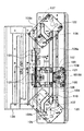
次に、前記スタックトレイ200及びサンプルトレイ201につき、図8及び図9に基づいて詳細に説明する。
【0081】
スタックトレイ200及びサンプルトレイ201は、状況に応じてそれぞれに使い分けられるもので、下方に配されるスタックトレイ200が、コピー出力、プリンタ出力等におけるシート束を受け取るときに選択され、上方に配されるサンプルトレイ201が、サンプル出力、割り込み出力、スタックトレイのオーバーフロー時の出力、ファンクション出力、ジョブ混載時の出力等でのシートを受け取るときに選択される。
【0082】
そして、これらのスタックトレイ200及びサンプルトレイ201は、それぞれにトレイベースプレート202,203に保持されると共に、該各ベースプレート202,203に取付け枠板204,205を介して固定したステッピングモータM200,M201を用いることで、個々に独立して上下の昇降方向へ自走可能にされており、この場合、双方共に、ほば同一の態様に構成されることから、ここでは、主にスタックトレイ200側についてのみ述べる。
【0083】
すなわち、前記シート処理装置1の両端部には、1対のフレーム250,250が上下方向に設けられると共に、該フレーム250,250に対してそれぞれに上下方向のガイドレール部を兼ねるラックギア部材251,251が取り付けられており、前記トレイベースプレート202の一方(シート幅方向を基準にして左端側に対応)から延長された後端部と、これに対向(同様に右端側に対応)する取付け枠板204から延長された後端部とにそれぞれ回転自在に設けられている1対のガイドコロ206を用い、該各ガイドコロ206を対応する各ガイドレール部内に嵌挿させることで、前記スタックトレイ200を上下に昇降可能に保持させ、かつ一方のフレーム250の折り返された端縁に規制部材208aを係合させることで、シート幅方向のガタつきを拘束して規制するようにしている。
【0084】
一方、ステッピングモータM200の回転出力は、タイミングベルト211を介して駆動軸213のプーリ212に伝達される。そして、駆動軸213には、ばね216で付勢されて軸方向に摺動のみ可能にしたラチエットホイール215が設けられており、該ラチエットホイール215は、軸上の駆動ギア214に一方向係合させてある。また、駆動ギア214に対しては、従動軸208上の両端部に配したアイドラギア207,207の一方が噛合され、かつ該各アイドラギア207,207は、それぞれに昇降ギア209,209を介して前記ラックギア部材251,251に噛合させる。つまり、前記スタックトレイ200は、これらのギアトレーンからなる駆動系を介して上下方向に昇降自在にされる。
【0085】
また、前記駆動軸213上の駆動ギア214に一方向付勢係合されるラチエットホイール215は、前記スタックトレイ200の下降時にあって、例えば、異物等を挟んで駆動系が破損したりすることのないように設けられるもので、ここでは、ばね216に所要程度の付勢力を付与しておき、該スタックトレイ200の上昇時においてのみ、あらかじめ設定されている条件対応にばね216の付勢力に抗し空回りすることで防護するようになっており、この空回り状況、つまり異常が発生した場合には、直ちにステッピングモータM200の駆動を停止させるべく、アイドラギア207,207のフランジ部に形成したクロックスリット等をセンサS201によって検出させるようになっている。なお、センサS201に関しては、通常動作時における脱調検知のためにも用いられる。
【0086】
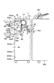
続いて、前記スタックトレイ200及びサンプルトレイ201の昇降位置制御のための各センサ配置について述べる。
【0087】
センサS202は、サンプルトレイ201の積載エリア検知のためのセンサであり、該サンプルトレイ201の上昇限位置検知センサS203aから処理トレイシート面検知センサS205までのエリアに属する範囲に位置していることを検知する。
【0088】
センサS203bは、第2の排出ローラ対9からサンプルトレイ201上に排出されるシートPが所定枚数に達したことを検知のためのセンサであり、ここでは、ノンソートシート面検知センサS204からシート積載枚数1000枚相当の位置に配置される。
【0089】
センサS203cは、処理トレイ130からサンプルトレイ201上に排出されるシートPが所定枚数に達したことを検知のためのセンサであり、同様に、シート面検知センサS205からシート積載枚数2000枚相当の位置に配置される。
【0090】
センサS203dは、スタックトレイ200が処理トレイ130からシートPを受け取るときの積載量の高さを制限するためのセンサであり、シート面検知センサS205からシート積載枚数2000枚相当の位置に配置される。
【0091】
センサS203eは、スタックトレイ200の下降限位置を設定するセンサである。
【0092】
また、スタックトレイ200及びサンプルトレイ201には、それぞれにシート有無検知センサ206a,206bが配置されている。
【0093】
そして、これらの各センサの内で、シート面検知センサS204,S205のみが、シートPの一方の側縁から他方の側縁への光透過によってその有無を検知する光透過型に設定されており、ここでは、そのシート面検知手法として、各シー卜面検知センサS204,S205の下方から、これを覆う位置まで各トレイ200,201を上昇させた状態がイニシャルであり、シート積載後にセンサ光軸が現れるまで下降させ、その後、再びセンサ光軸を覆うまで上昇させることを繰り返すのである。
【0094】
次に、本シート処理装置におけるシートPの流れにをシートサイズA4に説明する。
【0095】
〈ノンソートモード時のシートPの流れ〉
ユーザが、画像形成装置の排紙モードの設定をノンソートに指定したときは、図10に示されているように、シート処理装置1の第1切替えフラッパ11がノンソートパス21側にシートPを受け入れるべく切り替えられており、この状態で、入口ローラ対2、第1搬送ローラ対3、及びバッファローラ5がそれぞれに回転駆動され、画像形成装置300から排出されてくるシートPを装置内に取り込んでノンソートパス21に向けて搬送する。そして、ノンソートパスセンサ33によってシートPの後端が検知されると、第2排出ローラ対9は、積載に適した速度で回転駆動され、サンプルトレイ201上にシートPを排出して積載させる。
【0096】
〈ステイプルソートモード時のシートPの流れ〉
ユーザが、画像形成装置の排紙モードの設定をステイプルソートに指定したときは、図11に示されているように、シート処理装置1の第1切替えフラッパ11、及び第2切替えフラッパ10がソートパス22側にシートPを受け入れるべく切り替えられており、この状態で、入口ローラ対2、第1搬送ローラ対3、及びバッファローラ5がそれぞれに回転駆動され、画像形成装置300から排出されてくるシートPを装置内に取り込んでソートパス22に向けて搬送する。そして、シートPの後端が最終段のコロ14を抜けたところで、第1排出ローラ対7を構成する排出ローラ7aのローレットベルト8及びコロ7bによって処理トレイ130上に排出される。この場合、揺動ガイド150が上方に開くことで束排出ローラ対180の下部排出ローラ180aに対して上部排出ローラ108bが離間されており、かつ出没トレイ170が突出位置に突き出されているので、このように第1排出ローラ対7によってシートPを処理トレイ130上に排出させても、シートPの先端部の垂れ下がり、及び次に述べる戻り不良等を生じたりせず、該処理トレイ130上でのシートPの整列性が良好に高められる。
【0097】
処理トレイ130上に排出されたシートPは、自重によって後端ストッパ131側へ戻り始め、かつこれに加えて、ホームポジションで停止していたパドル160の反時計方向への回転に伴って該戻り作用が助長される。シートPの後端が後端ストッパ131に突き当てられて停止すると、パドル160の回転も停止され、ついで、整合部材141,142によるシートPの整合がなされ、その後、ステイプル動作によるシート束の綴じ、揺動ガイド150を閉じた状態での束排出ローラ対180による排出動作によって、該シート束がスタックトレイ200上に積載される。
【0098】
一方、その間に、画像形成装置300から排出されてくるシートPは、図12に示すように、第2切替えフラッパ10の切り替え作動でバッファローラ5に巻き付けられ、バッファパスセンサ32から所定距離だけ進んだところで、該バッファローラ5の停止で待機しており、次のシートPの先端が入口センサ31から所定距離だけ進んだ地点で、図13に示すように、バッファローラ5の回転に伴い、1枚目のシートP1よりも2枚目のシートP2の方が所定長さだけ先行して重ねあわされた状態で、図14に示すように、再びバッファローラ5に巻き付けるもので、さらに、3枚目のシートP3についても同様にバッファローラ5に巻き付けるのであり、その後、図15に示すように、第2切替えフラッパ10を再切り替えして、このように先端を所定長さずつずらせて重ねあわせた3枚のシートP1,P2,P3をソートパス22に搬送させる。
【0099】
この時点で、前記シート束の束排出動作は終了しており、ここでは、図16に示すように、揺動ガイド150が閉じられたまま、排出方向に正転している束排出ローラ対180a,180bが前記搬送されてくる3枚のシートP1,P2,P3を一旦、受け取る。そして、図17に示すように、3枚のシートPの終端が第1排出ローラ対7a,7bを抜けて処理トレイ130面上に接した時点において、束排出ローラ対180a,180bが逆転して迎え入れた3枚のシートPを戻すようにすると共に、該3枚のシートPの終端が後端ストッパ131面に突き当てられる以前、例えば、図18 ( b )に示すように、相互にずれ間隔b,bをもつ3枚のシートPの終端と後端ストッパ131面との間に間隔aを残して接近した時点で、図18 ( a )に示すように、揺動ガイド150を開いて束排出ローラ対180a,180b間を離間させる。そして、4枚目以降のシートPは、1部目の動作と同様にソートパス22を通って処理トレイ130上に排出される。3部目以降は、2部目と同じ動作を繰り返し、設定部数分相当にスタックトレイ200上に積載して処理を終了する。
【0100】
先に述べたように、前記複数枚の重ね搬送において、各シートPは、搬送方向にオフセットされている。つまり、シートP1 に対してシートP2 が下流側にオフセットされ、シートP2 に対してシートP3 が下流側にオフセットされる。ここで、シートPの相互間のオフセット量と揺動ガイド150のローラ対離間(上昇)開始タイミングは、束排出ローラ対180a,180b間の戻し速度によるシートPの整定時間にかかわっている。すなわち、画像形成装置300の処理能力によって決まるもので、本実施の形態では、シートPの搬送速度750mm/s、オフセット量b=20mm程度、束排出ローラ戻し速度500mm/sにおいて、束排出ローラの離間開始位置は、シートP1 の終端が後端ストッパ131面に突き当てられる40mm程度(間隔aの値)手前に達した時点にタイミングを設定している。
【0101】
〈ソートモードの説明〉
ユーザが、画像形成装置300の原稿読取り部400に原稿をセットした後、不図示の操作部上でソートモードを指定し、かつ不図示のスタートキーをオンする。これによって、入口ローラ対2及び第1搬送ローラ対3は、図19に示すように、ステイプルソートモードの場合と同様にシートPを搬送して処理トレイ130上に積載する。整合手段140は、該処理トレイ130上のシート束を整合しながら、処理トレイ130上で少数枚を積載した後、図20に示すように、揺動ガイド150が閉じ方向に降りてきて、該少数枚のシート束を束搬送する。
【0102】
次に、搬送されてくるシートPは、ここでも、ステイプルソートモードの場合と同様にバッファローラ5に巻き付けられ、束排出終了後の処理トレイ130上に排出される。ここで、該束排出される少数枚束の枚数としては、実験結果によって20枚以下であることが望ましい。この枚数については、
原稿枚数≧束排出する枚数≦20枚
を満足する枚数になるように設定する。
【0103】
よって、プログラムを組むときに束排出する枚数を5枚に設定したならば、原稿枚数が4枚のときは4枚ずつ束排出する。また、原稿枚数が5枚以上の場合、例えば、14枚であったならば、5枚+5枚+4枚に分けて、それぞれに整合しかつ束排出する。
【0104】
1部目の束排出が全て終了したならば、左方側の整合部材141は、右方側の整合部材142と共に移動し、2部目の整合位置を一部目の整合位置に対してオフセットさせる(この動作の詳細については後述する)。2部目は、オフセットした位置で整合され、かつ1部目と同様に少数枚ずつ束排出される。2部目が終了したならば、各整合部材141,142は、先の1部目を整合した位置に戻って3部目を整合する。このようにして、図21に示すように、シート束の相互をずらせながら全ての設定部数を終了させる。
【0105】
〈整合及びステイプル動作の説明〉
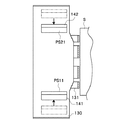
先ず、処理トレイ130上にシートPが1枚も無い場合、つまり、そのジョブの最初のシートP(3枚)が排出される際には、図22に示すように、ホームポジションで待機していた左方、右方の各整合部材141,142は、事前にそれぞれ排出されるシートPの幅に対して若干外側に逃げた位置PS11,PS21に移動させておく。
【0106】
上述の如く、3枚のシートPは、後端が後端ストッパ131、下面が各整合部材141,142の支持面141c,142cでそれぞれに支持されると、図23に示すように、各整合部材141,142は、位置PS12,PS22に移動して、シートPを第1整合位置190に移動かつ整合させる。その後、一方の整合部材141は、続いて排出されるシートPに備えて位置PS11に戻って待機し、シート排出がなされると、再び位置PS12に移動して、該排出されたシートPを第1整合位置190に移動かつ整合させる。
【0107】
このとき、他方の整合部材142は、位置PS22で停止し続けることで、基準位置としての役割りを果す。以上の動作が、その束の最終シートPに至るまで続けられる。従って、このように整合動作がなされるために、例えば、図24に示すような移動中のシートPの端部が、支持面142cの端部等に衝接して座屈を生じたりすることはない。
【0108】
整合が完了した1部目のシート束は、必要に応じて束シフトステイプルされ、かつ束排出されてスタックトレイ200に移送かつ積載される。
【0109】
続いて、2部目のシートP(3枚)が処理トレイ130に排出されるが、このとき、各整合部材141,142は、1部目と同様に位置PS11,PS21で待機してはいても、その整合位置は第2整合位置191に移る。この第2整合位置191は、図25に示すように、第1整合位置190に対して所定量Lだけ右方に位置する。
【0110】
すなわち、これ以降、シート束毎に整合位置を変えながらスタックトレイ200上に束積載が行われて、オフセット量Lによる仕分け積載が可能になるのである。
【0111】
ここで、前記オフセット量Lについては、ソートモードとステイプルモードとで変化させてもよい。例えば、ステイプルモード時には、束積載後に隣接する束の綴じ針同士の重なりを防げる量L1 (約15mm)とし、ソートモードでは、束識別の視認性が向上される量L2 (約20〜30mm)とすることにより、ステイプルモード時の整合移動距離が短縮されて処理速度の向上を図り得る。
【0112】
次に、ステイプルモード時にあって、ステイプラ101は、整合されるシート束に対する所望のクリンチ位置にあらかじめ待機しており、束の最終シートPの排出とその整合が完了した時点でステイプルするものである。なお、前記のようにシート束の整合位置は、束毎にオフセット量L対応に変化するが、これに応じてステイプラ101も移動する。
【0113】
また、ステイプラ101が、綴じモード(左方側端部の斜め綴じ、右方側端部の斜め綴じ、2ヶ所綴じ)に対応して向き替え移動する構成については、先に述べた通りである。しかし、該構成では、同一のステイプル姿勢(水平及び各傾斜状態)を維持できる範囲にも限りがあり、さらには、ステイプルを行うシート幅は多数存在し、異なる綴じモードに対して、同一の整合位置ではステイプルできない場合があるため、各綴じモードに対応して前記第1、第2の各整合位置190,191を変えてもよい。
【0114】
【発明の効果】
以上説明したように、本発明によれば、第1の積載手段上のシート束を、シート束整合位置、もしくは、シート束処理位置に対して交互に束シフトさせ、シート束の束排出位置を変更して束排出するようにしたので、従来からの、第2の積載手段のオフセットによるオフセット積載による束識別性や、第2の積載手段上のオフセット積載性を損なうことなく、各種サイズのシートでも、その整合性を維持でき、かつ、安価な装置構成を実現できる。
【図面の簡単な説明】
【図1】本発明のシート処理装置の全体構成を示す正面図。
【図2】同じくステイプラと処理トレイ部の側面図。
【図3】同じく図2のa視図でステイプラ移動機構の平面図。
【図4】同じく図2のb視図でステイプラの背面図。
【図5】同じく揺動ガイドと処理トレイの縦断側面図。
【図6】同じく整合手段と綴じ手段との配置関係示す平面説明図。
【図7】同じく処理トレイ、整合部材移動機構の背面図。
【図8】同じくスタックトレイ移動機構の平面図。
【図9】同じくスタックトレイまわりのセンサ配置図。
【図10】同じくノンソートモード時のシート処理装置の動作図。
【図11】同じくステイプルソートモード時のシート処理装置の動作図。
【図12】同じくステイプルソートモード時のシート処理装置の動作図。
【図13】同じくステイプルソートモード時のシート処理装置の動作図。
【図14】同じくステイプルソートモード時のシート処理装置の動作図。
【図15】同じくステイプルソートモード時のシート処理装置の動作図。
【図16】同じくステイプルソートモード時のシート処理装置の動作図。
【図17】同じくステイプルソートモード時のシート処理装置の動作図。
【図18】同じくステイプルソートモード時のシート処理装置の動作図。
【図19】同じくソートモード時のシート処理装置の動作図。
【図20】同じくソートモード時のシート処理装置の動作図。
【図21】同じくソートモード時のシート束の積載図。
【図22】同じくシート束の整合動作を示す処理トレイの平面図。
【図23】同じくシート束の整合動作を示す処理トレイの平面図。
【図24】同じくシート束の整合動作を示す処理トレイの平面図。
【図25】同じくシート束の整合動作を示す処理トレイの平面図。
【図26】本発明に係るシート処理装置が適用された画像形成装置の概要を示す縦断正面図。
【符号の説明】
P シート
130 処理トレイ(第1の積載手段)
140 整合手段
141 手前整合部材(整合手段)
142 奥整合部材(整合手段)
180 束排出ローラ対(束搬送手段)
180a 下束排出ローラ
180b 上束排出ローラ
200 スタックトレイ(第2のシート積載手段)
201 サンプルトレイ
300 画像形成装置本体
302 排出ローラ対(本体排出手段)
600 画像形成部(画像形成手段)
310 画像形成装置本体の制御装置(制御手段)[0001]
BACKGROUND OF THE INVENTION
The present inventionImage formationFor example, for example,, ExhaustProcess the issued sheetRumoRelated to.
[0002]
[Prior art]
Conventionally, a first sheet stacking unit (hereinafter referred to as a processing tray) for aligning image-formed sheets and performing sheet processing (also referred to as post-processing) such as staple binding, and sheet bundles are received and stacked for each bundle. Many devices including a second sheet stacking unit (hereinafter referred to as a stack tray) have already been proposed and implemented, including the technique disclosed in, for example, Japanese Patent Laid-Open No. 2-144370. Among them, in order to make it possible to identify the bundle on the stack tray, or to prevent the stacking height of the staple binding portion from increasing and the upper surface of the sheet bundle from becoming a uniform surface, Offset loading, in which a predetermined amount is alternately shifted, is also devised.
[0003]
[Problems to be solved by the invention]
However, as an embodiment of the offset stacking, the stack tray itself isshiftIn the type, it was effective if the stacking capacity on the stack tray was small, but in the recent increase in capacity and processing of a large number of sheets, the load for shifting the stack tray increased, and the sheet bundle In order to maintain the loading state, further improvements are desired from the viewpoint of bundle breakage, dropping, and the like.
[0004]
Also, a type has been devised in which the alignment position of the sheet bundle on the processing tray is alternately changed for each bundle, and the sheet bundle is discharged from that position to enable offset on the stack tray. However, since the alignment position of the sheet bundle is different, it is necessary to move the sheet processing means (post-processing means) in accordance with the offset amount of the sheet bundle, and the configuration of the post-processing means section becomes complicated.
[0005]
In addition, the alignment conditions of other mechanisms differ depending on the alignment position of the sheet bundle (for example, the amount of movement of the sheet, the alignment direction of the sheet, and other load conditions during alignment with respect to the sheet discharge position). There is a possibility that accurate sheet alignment cannot be obtained.
[0006]
The present invention simplifies the configuration for avoiding misalignment of sheets while enabling offset stacking of sheet bundles on the stack tray.Image formationThe object is to provide an apparatus.
[0007]
[Means for Solving the Problems]
The present inventionAn image forming unit that forms an image on a sheet, a discharging unit that discharges a sheet formed by the image forming unit, and the discharging unit.A first stacking unit for stacking discharged sheets, and a sheet bundle stacked on the first stacking unit;CarryA bundle conveying means for sending;A second stacking unit that stacks the sheet bundle conveyed by the bundle conveying unit;Sheet bundle stacked on the first stacking meansIt is possible to perform predetermined post-processing at different processing positionsSheet bundle processing means;An alignment unit that aligns sheets at different alignment positions on the first stacking unit in a direction that intersects with the conveyance direction of the sheet bundle by the bundle conveyance unit according to the sheet size and the processing position; and the sheet bundle processing A bundle shifting means for shifting the sheet bundle stacked on the first stacking means in a direction crossing the transport direction after the post-processing by means;The bundle conveying unit, the bundle shifting unit, and the sheet bundle processing unitBehaviorControl means for controllingIn the case of a sheet having a size having a first sheet width in a direction intersecting the transport direction, the aligning unit aligns the sheets by changing the alignment position in a direction intersecting the transport direction for each bundle, In the case of a sheet having a second sheet width smaller than the first sheet width, the sheets are aligned without changing the alignment position for each bundle, and the control unit stacks the sheets on the first stacking unit. The post-processing by the sheet bundle processing means is executed after the aligning operation by the aligning means according to the size and processing position of the sheet, and the post-processing is performed in the case of a sheet having a size having the second sheet width. After execution, the shift unit causes the shift operation to be performed every other bundle, and then the bundle conveying unit conveys the sheet bundle to the second stacking unit, so that the first sheet width is increased. After the size of the case of sheet the post execution that, without performing the shift operation by the shift means, to convey the sheet bundle to the second stacking means by the bundle conveying meansIt is characterized by that.
[0011]
Also bookThe inventionThe sheet bundle processing means is a sheet bundle binding means.It is characterized by that.
[0012]
The present invention also provides the bundle shifting means.IsIt is also characterized by serving as a combination means. Further, according to the present invention, the control unit determines a shift direction or a movement amount of the sheet bundle by the bundle shift unit according to a sheet size of the sheet on the first stacking unit and a processing position by the sheet bundle processing unit. It is characterized by selecting.
[0013]
[Action]
Based on the above configuration, the sheet bundle discharged and stacked on the first stacking unit is subjected to alignment by the alignment unit, bundle shift by the bundle shift unit, sheet processing by the sheet bundle processing unit, and the like. Show.
[0014]
(A),The alignment position of the sheet bundle in the first stacking tray is the same, and after the alignment of the sheet bundle is completed, the sheet bundle is shifted in the alignment direction, and then the bundle conveyed to the second stacking tray is not shifted. By alternately performing the bundles to be conveyed, offset stacking on the second stacking unit can be performed, and deterioration of sheet bundle alignment can be prevented.
[0015]
(B), (a)In the same manner as described above, after completion of alignment of the sheet bundle, after performing processing operations such as staple binding, the bundle that is bundle-shifted and the bundle that is not bundle-shifted are alternately bundled and stacked on the stack tray.
[0016]
(C), (b)In the same manner as above, or a bundle that has been processed after the bundle shift and a bundle that has been processed without the bundle shift are alternately conveyed and offset-stacked on the stack tray.
[0017]
(D),Since the aligning means also serves as the bundle shifting means, it is possible to provide a more inexpensive apparatus configuration.
[0018]
DETAILED DESCRIPTION OF THE INVENTION
Hereinafter, preferred embodiments of a sheet processing apparatus and an image forming apparatus including the same according to the present invention will be described in detail with reference to FIGS.
[0019]
First, an image forming apparatus according to the present invention, here, an image forming apparatus including a sheet processing apparatus will be described.
[0020]
Based on FIG. 26, the configuration of an image forming apparatus including a document conveying device and a sheet processing device will be described.
[0021]
The
[0022]
The wide belt is in contact with the
[0023]
A copying machine main body 1 'as an image forming apparatus main body includes an image input unit 200' (hereinafter referred to as a reader unit) and an image output unit 300 (hereinafter referred to as a printer unit).
[0024]
The
[0025]
Next, the
[0026]
[0027]
812 is a photosensitive drum,
[0028]
Reference numeral 817 denotes a conveyance belt that conveys a sheet material on which an image is formed, 818 denotes a fixing device, 819 denotes a conveyance roller, and 820 denotes a flapper. The sheet material on which the image is formed is guided to a main body discharge roller (main body discharge means) 821 by a flapper 820 and discharged to a downstream sheet processing apparatus.
[0029]
Depending on the set number of copies for a single document placed on the platen, the photosensitive drum812An image is formed on the sheet, and sheet materials for the number of copies are fed from any of the
[0030]
When the required number of copies is formed, the document is discharged from the platen, and the next document is positioned on the platen. The same applies hereinafter.
[0031]
An
[0032]
The sheet material has the image surface facing upward. In the case of multiple copying, the sheet material is guided to the
[0033]
The sheet materials stacked on the
[0034]
First, one-sided copying is performed according to the number of copies set for one document placed on the platen, and these are stacked on the
[0035]
An image-formed sheet discharged from the copying machine main body is discharged to a sheet processing apparatus (also referred to as a finisher) 1 by a main body discharge roller (main body discharge means) 302.
[0036]
In the non-sort mode, the sheet carried from the copying machine
[0037]
Next, the sheet processing apparatus according to the present invention will be described.
[0038]
<Overview of the entire sheet processing apparatus>
First, the main components of the sheet processing apparatus will be described.
[0039]
FIG. 1 is an overall cross-sectional view schematically showing a schematic configuration of a sheet processing apparatus according to the present embodiment.
[0040]
In the configuration of the sheet processing apparatus (hereinafter referred to as “finisher”) 1 shown in FIG. 1,
[0041]
[0042]
[0043]
180b is supported by the
[0044]
<Detailed description of staple unit>
Next, regarding the staple unit (binding means) 100 constituting one of the main parts of the present invention, in particular, FIG. 2 (a side view corresponding to the main cross section), FIG. 3 (a plan view in the direction of arrow a in FIG. 2) and This will be described in detail with reference to FIG. 4 (a rear view in the direction of arrow b in FIG. 2).
[0045]
A stapler (binding means) 101 is fixed on the moving table 103 via a
[0046]
The moving table 103 has a pair of
[0047]
Each of the rolling
[0048]
Here, as is apparent from FIG. 3, the series of hole-shaped
[0049]
The
[0050]
<Detailed explanation of stapler moving mechanism>
Next, the moving mechanism of the
[0051]
One rolling
[0052]
Further, a
[0053]
<Detailed explanation of rear end stopper>
Next, the trailing
[0054]
The trailing
[0055]
Therefore, in this case, with respect to the
[0056]
Further, a staple stopper (indicated by a two-dot chain line in FIG. 2) 113 having a support surface having the same shape as the abutting support surface 13la of the
[0057]
<Overview of processing tray unit>
Next, the
[0058]
The
[0059]
In this case, the
[0060]
Then, the sheet P discharged from the first
[0061]
Further, as described above, one
[0062]
<Detailed description of alignment means>
Next, the aligning means 140 constituting the other main part of the present invention will be described in detail with reference to FIGS. 5 and 6 and FIGS. 7 and 8 that are C arrow views of FIG.
[0063]
A pair of aligning
[0064]
That is, in summary, the alignment surfaces 14la and 142a are arranged to face the
[0065]
The
[0066]
<Relationship between alignment position, bundle discharge position, and binding position>
Next, the relationship among the sheet bundle alignment position, the bundle discharge position to the
[0067]
Obviously, based on the above configuration, the alignment direction and alignment position of the sheet bundle with respect to the sheet discharge position can be arbitrarily set. Further, as described above, the binding processing position is divided into three areas, that is, a position that can be moved in the right tilt position, a position that can be moved in the left tilt position, and a position that can be moved in the parallel position. In this embodiment, the alignment position of the sheet bundle is set according to the above conditions and the sheet size.
[0068]
<A4 size (alignment position, binding position, bundle discharge position are the same)>
In the above-mentioned size, which has relatively good alignment, can be tilted, and requires high productivity, as shown in FIG. Alternately, bundle alignment is performed by changing the alignment position by a predetermined amount. Thereafter, the binding process is performed, and the bundle is discharged at the same position.
[0069]
<A4R size (the alignment position and the binding position are the same, but the bundle discharge position is different)>
For sizes that are poorly aligned and can be partly tilted, bundle alignment is performed with the alignment position and alignment direction fixed at the sheet discharge position, as shown in FIG. 6B, and then binding is performed. Execute the process. In the subsequent operation, the bundle to be discharged as it is and the aligning means pair are moved in the same direction by a predetermined amount to perform the bundle shift, and then the bundle to be discharged is alternately performed.
[0070]
Note that black arrows in FIG. 6 indicate the bundle shift direction of the sheet bundle.
[0071]
<B5R size (the binding position is the same as the bundle discharge position but the alignment position is different)>
When the size is poor and the tilting posture is impossible, bundle alignment is performed with the alignment position and alignment direction being constant with respect to the sheet discharge position as shown in FIG. Thereafter, the bundle shift is performed while changing the movement amount of the matching means pair in the same direction and alternately. Thereafter, the binding process is performed, the bundle is discharged as it is, and the offset stacking is performed.
[0072]
As described above, the sheet bundle on the
[0073]
Further, after the bundle processing by the
[0074]
<Detailed explanation of swing guide>
Next, the
[0075]
As described above, the
[0076]
In a normal case, when each individual sheet P is discharged onto the
[0077]
<Detailed description of retractable paddle>
Next, the pull-in
[0078]
The pull-in
[0079]
Then, when the sheet P is discharged onto the
[0080]
<Detailed explanation of stack tray and sample tray>
Next, the
[0081]
The
[0082]
The
[0083]
That is, a pair of
[0084]
On the other hand, the rotation output of the stepping motor M200 is transmitted to the
[0085]
In addition, the
[0086]
Next, sensor arrangements for controlling the raising / lowering positions of the
[0087]
The sensor S202 is a sensor for detecting the stacking area of the
[0088]
The sensor S203b is a sensor for detecting that a predetermined number of sheets P are discharged from the second
[0089]
The sensor S203c is a sensor for detecting that a predetermined number of sheets P are discharged from the
[0090]
The sensor S203d is a sensor for limiting the height of the stacking amount when the
[0091]
The sensor S203e is a sensor that sets the lower limit position of the
[0092]
The
[0093]
Of these sensors, only the sheet surface detection sensors S204 and S205 are set to a light transmission type that detects the presence or absence of light by transmitting light from one side edge of the sheet P to the other side edge. Here, as the sheet surface detection method, the state in which the
[0094]
Next, the flow of the sheet P in the sheet processing apparatus will be described as a sheet size A4.
[0095]
<Flow of sheet P in non-sort mode>
When the user specifies non-sort as the paper discharge mode setting of the image forming device,101, the
[0096]
<Flow of sheet P in staple sort mode>
When the user specifies the paper discharge mode setting of the image forming apparatus to staple sort,11As shown in FIG. 4, the
[0097]
The sheet P discharged onto the
[0098]
On the other hand, the sheet P discharged from the
[0099]
At this point, the sheet bundle bundle discharging operation has been completed.16As shown in FIG. 3, the bundle
[0100]
As described above, in the overlap conveyance of the plurality of sheets, each sheet P is offset in the conveyance direction. That is, the sheet P1 Against sheet P2 Is offset downstream and the sheet P2 Against sheet PThree Is offset downstream. Here, the offset amount between the sheets P and the roller pair separation (rise) start timing of the
[0101]
<Description of sort mode>
After the user sets a document on the
[0102]
Next, the conveyed sheet P is again wound around the
Number of documents ≥ number of sheets to be discharged ≤ 20
Is set so that the number of images satisfies.
[0103]
Therefore, if the number of bundles to be ejected is set to 5 when creating a program, if the number of documents is 4,4 pieces eachBunch out. Further, when the number of documents is 5 or more, for example, if it is 14 sheets, it is divided into 5 sheets + 5 sheets + 4 sheets, aligned and discharged in a bundle.
[0104]
When the first set of bundles has been completely discharged, the
[0105]
<Description of alignment and stapling operation>
First, when there is no sheet P on the
[0106]
As described above, when the three sheets P are supported by the
[0107]
At this time, the
[0108]
The first sheet bundle that has been aligned is bundle-shifted and stapled as necessary, and the bundle is discharged and transferred to and stacked on the
[0109]
Subsequently, the second copy sheet P (three sheets) is discharged to the
[0110]
That is, after that, bundle stacking is performed on the
[0111]
Here, the offset amount L may be changed between the sort mode and the staple mode. For example, in the staple mode, an amount L that can prevent the binding needles of adjacent bundles from being stacked after stacking the bundles.1 (Approx. 15 mm), and in sort mode, the amount L for improving the visibility of bundle identification2 By setting (about 20 to 30 mm), the alignment moving distance in the staple mode can be shortened and the processing speed can be improved.
[0112]
Next, in the stapling mode, the
[0113]
In addition, the configuration in which the
[0114]
【The invention's effect】
As described above, according to the present invention, the sheet bundle on the first stacking unit is alternately shifted with respect to the sheet bundle alignment position or the sheet bundle processing position, and the sheet bundle bundle discharge position is set. Since the bundle is discharged after being changed, sheets of various sizes can be used without impairing the conventional bundle identification by offset stacking by the offset of the second stacking means and the offset stackability on the second stacking means. However, the consistency can be maintained and an inexpensive apparatus configuration can be realized.
[Brief description of the drawings]
FIG. 1 is a front view showing an overall configuration of a sheet processing apparatus according to the present invention.
FIG. 2 is a side view of the stapler and the processing tray portion.
3 is a plan view of the stapler moving mechanism as seen from a in FIG.
4 is a rear view of the stapler in the same view as in FIG. 2b.
FIG. 5 is a longitudinal side view of the swing guide and the processing tray.
FIG. 6 is an explanatory plan view showing the positional relationship between the matching means and the binding means.
FIG. 7 is a rear view of the processing tray and alignment member moving mechanism.
FIG. 8 is a plan view of the stack tray moving mechanism.
FIG. 9 is a sensor layout diagram around the stack tray.
FIG. 10 is an operation diagram of the sheet processing apparatus in the non-sort mode.
FIG. 11 is an operation diagram of the sheet processing apparatus in the staple sort mode.
FIG. 12 is an operation diagram of the sheet processing apparatus in the staple sort mode.
FIG. 13 is an operation diagram of the sheet processing apparatus in the staple sort mode.
FIG. 14 is an operation diagram of the sheet processing apparatus in the staple sort mode.
FIG. 15 is an operation diagram of the sheet processing apparatus in the staple sort mode.
FIG. 16 is an operation diagram of the sheet processing apparatus in the staple sort mode.
FIG. 17 is an operation diagram of the sheet processing apparatus in the staple sort mode.
FIG. 18 is an operation diagram of the sheet processing apparatus in the staple sort mode.
FIG. 19 is an operation diagram of the sheet processing apparatus in the sort mode.
FIG. 20 is an operation diagram of the sheet processing apparatus in the sort mode.
FIG. 21 is a stacking diagram of sheet bundles in the same sort mode.
FIG. 22 is a plan view of the processing tray showing the sheet bundle aligning operation.
FIG. 23 is a plan view of the processing tray showing the sheet bundle aligning operation.
FIG. 24 is a plan view of the processing tray showing the sheet bundle aligning operation.
FIG. 25 is a plan view of the processing tray showing the sheet bundle aligning operation.
FIG. 26 is a longitudinal front view showing an outline of an image forming apparatus to which the sheet processing apparatus according to the invention is applied.
[Explanation of symbols]
P sheet
130 processing tray (first loading means)
140 Alignment means
141 Front alignment member (alignment means)
142 Back alignment member (alignment means)
180 Bundle discharge roller pair (Bundle transport means)
180a Lower bundle discharge roller
180b Upper bundle discharge roller
200 Stack tray (second sheet stacking means)
201 Sample tray
300 Image forming apparatus main body
302 discharge roller pair (main body discharge means)
600 Image forming unit (image forming means)
310 Control Device (Control Unit) of Image Forming Apparatus Main Body
Claims (4)
前記画像形成手段により画像形成されたシートを排出する排出手段と、
前記排出手段から排出されるシートを積載する第1の積載手段と、
前記第1の積載手段上に積載されたシート束を搬送する束搬送手段と、
前記束搬送手段により束搬送されるシート束を積載する第2の積載手段と、
前記第1の積載手段に積載されたシート束の異なる処理位置に、所定の後処理を行うことが可能なシート束処理手段と、
シートサイズ及び前記処理位置に応じて、前記第1の積載手段上の、前記束搬送手段によるシート束の搬送方向と交差する方向の異なる整合位置にシートを整合する整合手段と、
前記シート束処理手段による前記後処理後、前記搬送方向と交差する方向に前記第1の積載手段に積載されたシート束をシフトする束シフト手段と、
前記束搬送手段、前記束シフト手段及び前記シート束処理手段の動作を制御する制御手段と、を備え、
前記整合手段は、前記搬送方向と交差する方向において第1のシート幅を有するサイズのシートの場合、一束ごとに前記整合位置を前記搬送方向と交差する方向に変えてシートを整合し、前記第1のシート幅よりも小さい第2のシート幅を有するサイズのシートの場合、束ごとに前記整合位置を変えることなくシートを整合し、
前記制御手段は、前記第1の積載手段上に積載されたシートのサイズ及び処理位置に応じた前記整合手段による整合動作後に前記シート束処理手段による前記後処理を実行させ、
さらに、前記第2のシート幅を有するサイズのシートの場合は前記後処理実行後、前記シフト手段により一束おきにシフト動作を実行させた後、前記束搬送手段によりシート束を前記第2の積載手段へ搬送させ、前記第1のシート幅を有するサイズのシートの場合は前記後処理実行後、前記シフト手段によるシフト動作を行うことなく、前記束搬送手段によりシート束を前記第2の積載手段へ搬送させることを特徴とする画像形成装置。 Image forming means for forming an image on a sheet;
A discharge means for discharging the sheet image-formed by the image forming means;
First stacking means for stacking sheets discharged from the discharge means;
A bundle conveying means for feeding transportable sheet bundle stacked on the first stacking means,
A second stacking unit that stacks the sheet bundle conveyed by the bundle conveying unit;
Sheet bundle processing means capable of performing predetermined post-processing at different processing positions of the sheet bundle stacked on the first stacking means;
An aligning unit that aligns sheets at different alignment positions on the first stacking unit in a direction that intersects with the conveying direction of the sheet bundle by the bundle conveying unit according to the sheet size and the processing position;
A bundle shifting means for shifting the sheet bundle loaded on the first stacking means in a direction intersecting the transport direction after the post-processing by the sheet bundle processing means;
Control means for controlling the operation of the bundle conveying means, the bundle shifting means and the sheet bundle processing means,
In the case of a sheet having a size having a first sheet width in a direction intersecting the transport direction, the aligning unit aligns the sheets by changing the alignment position in a direction intersecting the transport direction for each bundle, In the case of a sheet having a second sheet width smaller than the first sheet width, the sheets are aligned without changing the alignment position for each bundle,
The control unit causes the sheet bundle processing unit to perform the post-processing after the alignment operation by the alignment unit according to the size and processing position of the sheets stacked on the first stacking unit;
Further, in the case of a sheet having a size having the second sheet width, after the post-processing is performed, the shift unit performs a shift operation every other bundle, and then the bundle conveying unit performs the sheet bundle. In the case of a sheet having a size having the first sheet width conveyed to the stacking unit, the sheet stacking unit performs the second stacking by the bundle transport unit without performing the shift operation by the shift unit after performing the post-processing. an image forming apparatus comprising Rukoto is conveyed to the unit.
Priority Applications (1)
| Application Number | Priority Date | Filing Date | Title |
|---|---|---|---|
| JP32091698A JP4124889B2 (en) | 1998-11-11 | 1998-11-11 | Image forming apparatus |
Applications Claiming Priority (1)
| Application Number | Priority Date | Filing Date | Title |
|---|---|---|---|
| JP32091698A JP4124889B2 (en) | 1998-11-11 | 1998-11-11 | Image forming apparatus |
Related Child Applications (1)
| Application Number | Title | Priority Date | Filing Date |
|---|---|---|---|
| JP2008067307A Division JP4474471B2 (en) | 2008-03-17 | 2008-03-17 | Sheet processing device |
Publications (3)
| Publication Number | Publication Date |
|---|---|
| JP2000143082A JP2000143082A (en) | 2000-05-23 |
| JP2000143082A5 JP2000143082A5 (en) | 2007-10-18 |
| JP4124889B2 true JP4124889B2 (en) | 2008-07-23 |
Family
ID=18126712
Family Applications (1)
| Application Number | Title | Priority Date | Filing Date |
|---|---|---|---|
| JP32091698A Expired - Lifetime JP4124889B2 (en) | 1998-11-11 | 1998-11-11 | Image forming apparatus |
Country Status (1)
| Country | Link |
|---|---|
| JP (1) | JP4124889B2 (en) |
Families Citing this family (3)
| Publication number | Priority date | Publication date | Assignee | Title |
|---|---|---|---|---|
| JP4750302B2 (en) * | 2001-03-13 | 2011-08-17 | キヤノン株式会社 | Sheet processing apparatus and image forming apparatus |
| JP5074354B2 (en) * | 2008-11-06 | 2012-11-14 | 株式会社リコー | Paper stacking apparatus and image forming apparatus |
| JP6541345B2 (en) | 2014-12-24 | 2019-07-10 | キヤノン株式会社 | Recording material processing apparatus and image forming apparatus |
-
1998
- 1998-11-11 JP JP32091698A patent/JP4124889B2/en not_active Expired - Lifetime
Also Published As
| Publication number | Publication date |
|---|---|
| JP2000143082A (en) | 2000-05-23 |
Similar Documents
| Publication | Publication Date | Title |
|---|---|---|
| JP3526226B2 (en) | Sheet processing apparatus and image forming apparatus having the same | |
| JP3740280B2 (en) | Sheet processing apparatus and image forming apparatus having the same | |
| JP3728178B2 (en) | Sheet processing apparatus and image forming apparatus | |
| JP3302307B2 (en) | Sheet processing apparatus and image forming apparatus having the same | |
| US7887037B2 (en) | Sheet process apparatus | |
| JP3559718B2 (en) | Sheet processing apparatus and image forming apparatus having the same | |
| JPH11147641A (en) | Sheet processor and image forming device provided with this sheet processor | |
| JP3051685B2 (en) | Sheet processing apparatus and image forming apparatus having the same | |
| JP3728039B2 (en) | Sheet processing apparatus and image forming apparatus having the same | |
| JP4208370B2 (en) | Sheet processing apparatus and image forming apparatus having the same | |
| JP4474471B2 (en) | Sheet processing device | |
| JP3352345B2 (en) | Sheet processing apparatus and image forming apparatus having the same | |
| JP4124889B2 (en) | Image forming apparatus | |
| JP4217314B2 (en) | Sheet processing apparatus and image forming apparatus having the same | |
| JPH11147654A (en) | Sheet processing device and image forming device provided with the device | |
| JP2000143056A (en) | Sheet processing device and image forming device provided with the same | |
| JP2000169036A (en) | Sheet treatment device and picture image forming device furnished with it | |
| JP4077961B2 (en) | Sheet processing apparatus and image forming apparatus having the same | |
| JP3193894B2 (en) | Sheet processing apparatus and image forming apparatus having the same | |
| JP3296763B2 (en) | Sheet processing apparatus and image forming apparatus having the same | |
| JP3453502B2 (en) | Sheet processing apparatus and image forming apparatus having the same | |
| JP4136276B2 (en) | Sheet processing apparatus and image forming apparatus | |
| JP3296136B2 (en) | Image forming system and finisher | |
| JP3302305B2 (en) | Sheet processing apparatus and image forming apparatus having the same | |
| JP3416691B2 (en) | Sheet processing apparatus and image forming apparatus having the same |
Legal Events
| Date | Code | Title | Description |
|---|---|---|---|
| A521 | Written amendment |
Free format text: JAPANESE INTERMEDIATE CODE: A523 Effective date: 20051107 |
|
| A621 | Written request for application examination |
Free format text: JAPANESE INTERMEDIATE CODE: A621 Effective date: 20051107 |
|
| A521 | Written amendment |
Free format text: JAPANESE INTERMEDIATE CODE: A523 Effective date: 20070905 |
|
| A977 | Report on retrieval |
Free format text: JAPANESE INTERMEDIATE CODE: A971007 Effective date: 20071001 |
|
| A131 | Notification of reasons for refusal |
Free format text: JAPANESE INTERMEDIATE CODE: A131 Effective date: 20071009 |
|
| A521 | Written amendment |
Free format text: JAPANESE INTERMEDIATE CODE: A523 Effective date: 20071207 |
|
| A02 | Decision of refusal |
Free format text: JAPANESE INTERMEDIATE CODE: A02 Effective date: 20080115 |
|
| A521 | Written amendment |
Free format text: JAPANESE INTERMEDIATE CODE: A523 Effective date: 20080317 |
|
| A911 | Transfer to examiner for re-examination before appeal (zenchi) |
Free format text: JAPANESE INTERMEDIATE CODE: A911 Effective date: 20080321 |
|
| TRDD | Decision of grant or rejection written | ||
| A01 | Written decision to grant a patent or to grant a registration (utility model) |
Free format text: JAPANESE INTERMEDIATE CODE: A01 Effective date: 20080415 |
|
| A01 | Written decision to grant a patent or to grant a registration (utility model) |
Free format text: JAPANESE INTERMEDIATE CODE: A01 |
|
| A61 | First payment of annual fees (during grant procedure) |
Free format text: JAPANESE INTERMEDIATE CODE: A61 Effective date: 20080507 |
|
| R150 | Certificate of patent or registration of utility model |
Free format text: JAPANESE INTERMEDIATE CODE: R150 |
|
| FPAY | Renewal fee payment (event date is renewal date of database) |
Free format text: PAYMENT UNTIL: 20110516 Year of fee payment: 3 |
|
| FPAY | Renewal fee payment (event date is renewal date of database) |
Free format text: PAYMENT UNTIL: 20120516 Year of fee payment: 4 |
|
| FPAY | Renewal fee payment (event date is renewal date of database) |
Free format text: PAYMENT UNTIL: 20120516 Year of fee payment: 4 |
|
| FPAY | Renewal fee payment (event date is renewal date of database) |
Free format text: PAYMENT UNTIL: 20130516 Year of fee payment: 5 |
|
| FPAY | Renewal fee payment (event date is renewal date of database) |
Free format text: PAYMENT UNTIL: 20140516 Year of fee payment: 6 |
|
| EXPY | Cancellation because of completion of term |