JP4046847B2 - Magnetic resonance imaging system - Google Patents
Magnetic resonance imaging system Download PDFInfo
- Publication number
- JP4046847B2 JP4046847B2 JP12919398A JP12919398A JP4046847B2 JP 4046847 B2 JP4046847 B2 JP 4046847B2 JP 12919398 A JP12919398 A JP 12919398A JP 12919398 A JP12919398 A JP 12919398A JP 4046847 B2 JP4046847 B2 JP 4046847B2
- Authority
- JP
- Japan
- Prior art keywords
- subject
- tomographic plane
- magnetic field
- movement
- imaging
- Prior art date
- Legal status (The legal status is an assumption and is not a legal conclusion. Google has not performed a legal analysis and makes no representation as to the accuracy of the status listed.)
- Expired - Fee Related
Links
Images

Landscapes
- Magnetic Resonance Imaging Apparatus (AREA)
Description
【0001】
【発明の属する技術分野】
本発明は、核磁気共鳴(NMR)現象を利用して被検体の任意断層面を透視撮像し画像表示する磁気共鳴イメージング装置に関し、特に、被検体の動きに対応して透視撮像の断層面位置を自動的に変え常に関心部位を画像として捕らえることができる磁気共鳴イメージング装置に関する。
【0002】
【従来の技術】
磁気共鳴イメージング装置は、核磁気共鳴(NMR)現象を利用して被検体中の所望の検査部位における原子核スピンの密度分布、緩和時間分布を計測して、この計測データから被検体の任意断層面を画像表示するものである。従来の磁気共鳴イメージング装置は、被検体が配置される空間に静磁場を発生する手段と、この静磁場へ加えられる傾斜磁場を発生する手段と、上記被検体の検査すべきスライス位置に対応した周波数の高周波パルス磁界を発生して照射する手段と、この照射により上記被検体のスライス位置から発生されるNMR信号を検出する手段とを備え、被検体の任意断層面を透視撮像するようになっていた。
【0003】
そして、上記磁気共鳴イメージング装置による被検体の任意断層面の透視撮像は、医師等の術者が被検体の病変部へ穿刺針や生検針を進める際の穿刺位置や進入方向をリアルタイムに確認したり、或いは被検体の関節部の動態検査を行うのに用いられている。この場合、透視撮像における撮像断層面の設定は、透視撮像中において固定としておくか、又は操作器により被検体テーブルを移動させ被検体を動かして変化させるか、或いは操作器により撮像断層面自体を平行移動又は回転させて変化させていた。
【0004】
【発明が解決しようとする課題】
しかし、このような従来の磁気共鳴イメージング装置においては、撮像断層面の設定を固定としておくか、又は被検体テーブルの移動により被検体を動かして変化させるか、或いは操作器により撮像断層面自体を平行移動又は回転させて変化させていたので、被検体の呼吸動や関節部の動き等の小さい変化に対しては撮像断層面の設定を追従させることができなかった。即ち、術者が被検体の病変部へ穿刺針や生検針を進める際、又は被検体の関節部の動態検査を行う際に、撮像断層面を被検体の呼吸動や関節部の動き等の小さい変化に対して自動的に追従させることはできなかった。したがって、被検体の動きに対応して関心部位の画像が見えたり、見えなかったりすることがあった。このことから、透視撮像の途中で撮像断層面の設定をし直すこともあり、円滑な撮像ができないと共に検査時間がかかり且つ被検体の負担も大きくなるものであった。
【0005】
そこで、本発明は、このような問題点に対処し、被検体の動きに対応して透視撮像の断層面位置を自動的に変え常に関心部位を画像として捕らえることができる磁気共鳴イメージング装置を提供することを目的とする。
【0006】
【課題を解決するための手段】
上記目的を達成するために、本発明による磁気共鳴イメージング装置は、被検体が配置される空間に静磁場を発生すると共に、この静磁場へ加えられる傾斜磁場を発生する磁場発生手段と、上記被検体の検査すべきスライス位置に対応した周波数の高周波パルス磁界を発生して照射する送信系と、この照射により上記被検体のスライス位置から発生されるNMR信号を検出する受信系と、この検出されたNMR信号を処理し画像表示する信号処理系とを備え、被検体の任意断層面を透視撮像する磁気共鳴イメージング装置において、上記被検体の動きを検出する手段を設け、この動き検出手段により被検体の動きを検出した位置で撮像位置決め画像を得ると共に、そのときの被検体の透視撮像の断層面を設定しておき、上記動き検出手段からの検出信号を上記信号処理系で参照し、上記検出信号を用いて該検出信号に対応する被検体の動き量を演算し、この被検体の動き量を用いて透視撮像の断層面位置を推定し、被検体の動きに対応して透視撮像の断層面位置を自動的に変えるようにしたものである。
【0007】
【発明の実施の形態】
以下、本発明の実施の形態を添付図面に基づいて詳細に説明する。
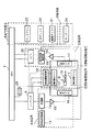
図1は本発明による磁気共鳴イメージング装置の実施の形態を示すブロック図である。この磁気共鳴イメージング装置は、NMR現象を利用して被検体中の所望の検査部位における原子核スピンの密度分布、緩和時間分布を計測して、この計測データから被検体の任意断層面を画像表示するもので、図1に示すように、静磁場発生磁石1と、傾斜磁場発生系2と、シーケンサ3と、送信系4と、受信系5と、信号処理系6と、中央処理装置(CPU)7と、操作部8とを有し、さらに動き検出手段9を備えて成る。
【0008】
上記静磁場発生磁石1は、被検体10が配置される空間において該被検体10の周りにその体軸方向又は体軸と直交する方向に均一な静磁場を発生する手段となるもので、上記被検体10の周りのある広がりをもった空間に永久磁石方式又は常電導方式或いは超電導方式の静磁場発生手段が配置されている。
【0009】
傾斜磁場発生系2は、上記静磁場発生磁石1で発生された静磁場へ加えられる傾斜磁場を発生する手段となるもので、X,Y,Zの三軸方向の傾斜磁場コイル11,11,…と、これらの傾斜磁場コイル11を駆動する傾斜磁場電源12とから成る。そして、後述のシーケンサ3からの命令に従ってそれぞれの傾斜磁場コイル11の傾斜磁場電源12を駆動することにより、X,Y,Zの三軸方向に傾斜磁場Gs(スライス方向傾斜磁場)、Gp(位相エンコード方向傾斜磁場)、Gf(周波数エンコード方向傾斜磁場)を被検体10に印加するようになっている。これらの傾斜磁場の印加方法により、上記被検体10に対するスライス位置や断層面を設定することができる。
【0010】
シーケンサ3は、上記被検体10の生体組織を構成する原子の原子核にNMRを起こさせる高周波パルスと傾斜磁場をある所定のパルスシーケンスで繰り返し印加し、被検体10の関心部位について計測データを収集するための制御手段となるもので、CPU7の制御で動作し、被検体10の断層像のデータ収集に必要な種々の命令を、上記傾斜磁場発生系2並びに後述の送信系4及び受信系5に送るようになっている。
【0011】
送信系4は、上記シーケンサ3から命令される高周波パルスにより被検体10の生体組織を構成する原子の原子核にNMRを起こさせるために該被検体の検査すべきスライス位置に対応した周波数の高周波パルス磁界を発生して照射する手段となるもので、高周波発振器13と変調器14と高周波増幅器15と照射コイル16とから成る。そして、上記高周波発振器13から出力された高周波パルスをシーケンサ3の命令に従って変調器14で振幅変調し、この振幅変調された高周波パルスを高周波増幅器15で増幅した後に、被検体10に近接して配置された照射コイル16に供給することにより、電磁波が上記被検体10に照射されるようになっている。
【0012】
受信系5は、上記送信系4の照射コイル16からの高周波パルス磁界の照射により上記被検体10のスライス位置から生体組織の原子核のNMRにより発生されるエコー信号(NMR信号)を検出する手段となるもので、受信コイル17と増幅器18と直交位相検波器19とA/D変換器20とから成る。そして、上記照射コイル16から照射された電磁波による被検体10の応答の電磁波(NMR信号)は被検体10に近接して配置された受信コイル17で検出され、増幅器18及び直交位相検波器19を介して二系列の収集データとされ、A/D変換器20に入力してディジタル信号に変換され、そのディジタル信号が後述の信号処理系6に送られるようになっている。
【0013】
信号処理系6は、上記受信系5からのディジタル信号を入力して処理し画像表示する手段となるもので、CPU7と、磁気ディスク21及び光ディスク22などの記録装置と、CRTなどのディスプレイ23とから成る。そして、上記CPU7でフーリエ変換、補正係数演算、画像再構成などの処理を行い、被検体10の任意断層面の原子核スピンの密度分布、緩和時間分布の計測データに所要の演算を行い、得られた分布データを画像化してディスプレイ23に断層像として表示するようになっている。
【0014】
また、CPU7は、上記各構成要素の動作を制御するものである。さらに、操作部8は、上記信号処理系6で行う処理の制御情報を入力するもので、入力器としてキーボード8やマウス、トラックボールなどを備えている。
【0015】
以上のような装置構成により、被検体10の任意断層面の透視撮像は、該被検体10のスライス位置からのNMR信号の計測、画像再構成などの処理、画像表示を短時間で繰り返し行うことで実施される。
【0016】
ここで、本発明においては、上記被検体10の動きを検出する動き検出手段9が設けられ、この動き検出手段9からの検出信号はA/D変換器25を介して前記CPU7に入力されるようになっている。そして、動き検出手段9で被検体10の動きを定量的に検出し、このアナログの検出信号はA/D変換器25によりディジタル信号に変換されてCPU7に入力され、CPU7は入力したディジタルの検出信号を参照して被検体10の透視撮像の断層面位置を推定し、その制御信号をシーケンサ3へ送る。シーケンサ3は、上記CPU7からの制御信号に応じて前述のように傾斜磁場電源12を制御し、被検体10に対する断層面を自動的に変えるように動作する。
【0017】
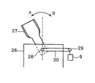
図2は、上記動き検出手段9の具体例を示す平面説明図である。この例は、被検体10の例えば頚部の動態検査を行う際に用いるもので、被検体10を寝載するテーブル26の一端部に、頭部を乗せる板状の頭受け台27を回転軸部28により矢印A,Bのように回動可能に設け、上記回転軸部28と動き検出手段9に設けられたプーリー29とをベルト30で連結し、該動き検出手段9としては例えばポテンショメータを用いたものである。そして、上記頭受け台27が回転軸部28を中心として矢印A,Bのように回動すると、その回動動作がベルト30を介してプーリー29に伝達され、このプーリー29の回転によりポテンショメータが回転され、該ポテンショメータにより上記頭受け台27の回動を定量的に検出するようになっている。この場合、上記頭受け台27上には被検体10の頭部が乗せられるので、その頭受け台27の回動により被検体10の頚部の動きを定量的に検出することができる。
【0018】
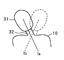
図3は、図2に示すテーブル26上に寝載された被検体10とその頚部に設定される透視撮像の断層面とを示す説明図である。このとき、被検体10の頭部31は図2に示す頭受け台27上に乗せられている。図3において、まず、被検体10の頭部31を頭受け台27ごと実線で示すように傾けると、その頚部32も同一方向に傾く。この位置で画像計測して、該位置における断層面Iaを実線で示すように設定する。次に、同じく頭部31を頭受け台27ごと破線で示すように傾けると、その頚部32も同一方向に傾く。この位置で画像計測して、該位置における断層面Ibを破線で示すように設定する。このとき、上記断層面Ia,Ibの設定時に、これらの位置に対応するポテンショメータ(9)からの検出信号が、被検体10の動きの情報としてA/D変換器25を介してCPU7に入力される。
【0019】
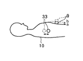
図4は、上記動き検出手段9の他の具体例を示す側面説明図である。この例は、被検体10の例えば腹部の病変部に穿刺針や生検針を進める際に用いるもので、被検体10の呼吸による病変部33の動きを検出する動き検出手段9として例えば呼吸動センサを腹部に取り付けたものである。この呼吸動センサは、被検体10の呼吸により内部の病変部33が例えば実線の位置と破線の位置のように動くのを、腹部の上面の実線の位置aと破線の位置bの動きで等価的に検出するもので、例えば腹部の周囲に巻き付けた部材の圧力変化や抵抗値変化などにより上記位置a,bの動きを検出するように構成されている。
【0020】
図5は、被検体10とその腹部の病変部33に設定される透視撮像の断層面とを示す平面説明図である。図4及び図5において、まず、被検体10が息をはいた状態では病変部33は実線の位置にあり、図5に示すようにこの位置で画像計測して該位置における断層面Iaを実線で示すように設定する。ここで、断層面Iaは、穿刺点34と実線で示す病変部33とを含む断面である。次に、被検体10が息をいっぱいに吸った状態では病変部33は破線の位置にあり、図5に示すようにこの位置で画像計測して該位置における断層面Ibを破線で示すように設定する。ここで、断層面Ibは、穿刺点34と破線で示す病変部33とを含む断面である。このとき、上記断層面Ia,Ibの設定時に、これらの位置に対応する呼吸動センサ(9)からの検出信号が、被検体10の動きの情報としてA/D変換器25を介してCPU7に入力される。
【0021】
次に、このように構成された磁気共鳴イメージング装置において透視撮像の断層面位置を推定して自動的に変える動作について、図6及び図7を参照して説明する。これらの図は、図2及び図3に示す被検体10の例えば頚部の動態検査を行う際の動作例を示すものである。
【0022】
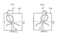
まず、図2において、テーブル26上に寝載された被検体10(図示せず)の頭部31を頭受け台27に乗せ、この頭受け台27を図2上で例えば矢印A方向に傾ける。このとき、上記被検体10の頚部32が矢印A方向に曲がる限度の位置まで傾ける。そして、この位置で画像計測し、図6(a)に示すような撮像位置決め画像IM1を得る。また、上記の撮像位置決め画像IM1から被検体10の頚部32についての透視撮像の断層面をIaのように設定する。この状態では、上記断層面Iaは、X,Yの直交座標軸のY軸に対する角度θaと、撮像中心からの距離Laとで規定される。さらに、このときの上記位置に対応する動き検出手段9(図2参照)からの検出信号の大きさをSaとする。
【0023】
次に、図2において、被検体10(図示せず)の頭部31を乗せた頭受け台27を例えば矢印B方向に傾ける。このとき、上記被検体10の頚部32が矢印B方向に曲がる限度の位置まで傾ける。そして、この位置で画像計測し、図6(b)に示すような撮像位置決め画像IM2を得る。また、上記の撮像位置決め画像IM2から被検体10の頚部32についての透視撮像の断層面をIbのように設定する。この状態では、上記断層面Ibは、X,Yの直交座標軸のY軸に対する角度θbと、撮像中心からの距離Lbとで規定される。さらに、このときの上記位置に対応する動き検出手段9(図2参照)からの検出信号の大きさをSbとする。
【0024】
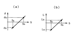
上記動き検出手段9からの検出信号Sa,Sbは、図1に示すA/D変換器25を介してCPU7へ入力される。これにより、CPU7は、上記の各情報Sa,Sb,θa,θb,La,Lbを用いて、図7(a)に示すように動き検出手段9からの検出信号の大きさSに対応する角度θを線形推定できるグラフを作成し、また、図7(b)に示すように検出信号の大きさSに対応する距離Lを線形推定できるグラフを作成する。
【0025】
このようなグラフを用いて、図2及び図3に示す被検体10の頚部32を矢印A,Bのように動かしながら透視撮像する際の断層面位置を、動き検出手段9からの検出信号Sを参照し、この検出信号Sの前述の図7(a),(b)のグラフ上の位置に対応する角度θ及び距離Lを線形推定することにより、図6と同様に角度θと距離Lとで規定されるものとして推定することができる。
【0026】
その後、このように推定された透視撮像の断層面位置の制御信号を図1に示すシーケンサ3へ送る。このシーケンサ3は、上記CPU7からの制御信号に応じて前述のように傾斜磁場電源12を制御し、被検体10に対する断層面を自動的に変える。これにより、被検体10の動きに対応して透視撮像の断層面位置を自動的に変え、常に関心部位を画像として捕らえることができる。
【0027】
なお、図7(a),(b)のグラフを作成する際に、情報Sa,Sbの点数を増やしてグラフを作成すれば、より精度の高い断層面位置の推定ができる。また、図6においては、断層面の位置決めを(a),(b)の2断面を使用して行ったが、これら2断面と直交するもう一つの断面を使用することにより、3次元画像への応用も可能である。
【0028】
また、図6及び図7は、図2及び図3に示す被検体10の例えば頚部の動態検査を行う際の動作例を示すものであるが、図4及び図5に示す被検体10の例えば腹部の病変部に穿刺針や生検針を進める際の動作例についても、上記と同様に撮像位置決め画像を得ると共に、動き検出手段9からの検出信号の大きさに対応して角度、距離などを線形推定できるグラフを作成すればよい。
【0029】
【発明の効果】
本発明は以上のように構成されたので、動き検出手段により被検体の動きを検出し、この動き検出手段により被検体の動きを検出した位置で撮像位置決め画像を得ると共に、そのときの被検体の透視撮像の断層面を設定しておき、信号処理系で上記動き検出手段からの検出信号を参照し、上記検出信号を用いて該検出信号に対応する被検体の動き量を演算し、この被検体の動き量を用いて透視撮像の断層面位置を推定し、被検体の動きに対応して透視撮像の断層面位置を自動的に変えることができる。これにより、例えば術者が被検体の病変部へ穿刺針や生検針を進める際、又は被検体の関節部の動態検査を行う際に、撮像断層面を被検体の呼吸動や関節部の動き等の小さい変化に対して自動的に追従させることができ、上記被検体の動きに対応して透視撮像の断層面位置を自動的に変え、常に関心部位を画像として捕らえることができる。このことから、従来のように透視撮像の途中で撮像断層面の設定をし直すことはなく、円滑な撮像ができると共に検査時間を短縮でき且つ被検体の負担も軽減することができる。
【図面の簡単な説明】
【図1】本発明による磁気共鳴イメージング装置の実施形態を示すブロック図である。
【図2】動き検出手段の具体例を示す平面説明図である。
【図3】テーブル上に寝載された被検体とその頚部に設定される透視撮像の断層面とを示す説明図である。
【図4】動き検出手段の他の具体例を示す側面説明図である。
【図5】被検体とその腹部の病変部に設定される透視撮像の断層面とを示す平面説明図である。
【図6】透視撮像の断層面位置を推定して自動的に変える動作を説明するもので、撮像位置決め画像を得る状態を示すものである。
【図7】動き検出手段からの検出信号の大きさに対応する角度又は距離を線形推定できるグラフを作成する状態を示すものである。
【符号の説明】
1…静磁場発生磁石
2…傾斜磁場発生系
3…シーケンサ
4…送信系
5…受信系
6…信号処理系
7…CPU
8…操作部
9…動き検出手段
10…被検体
25…A/D変換器
31…頭部
32…頚部
33…病変部
34…穿刺点
Ia,Ib…断層面
IM1,IM2…撮像位置決め画像[0001]
BACKGROUND OF THE INVENTION
The present invention relates to a magnetic resonance imaging apparatus that uses a nuclear magnetic resonance (NMR) phenomenon to perform radiographic imaging and display an image of an arbitrary tomographic plane of a subject, and in particular, tomographic plane position of fluoroscopic imaging corresponding to the movement of the subject. The present invention relates to a magnetic resonance imaging apparatus that can automatically change a region of interest and always capture a region of interest as an image.
[0002]
[Prior art]
The magnetic resonance imaging apparatus uses the nuclear magnetic resonance (NMR) phenomenon to measure the nuclear spin density distribution and relaxation time distribution at a desired examination site in the subject, and from this measurement data, the arbitrary tomographic plane of the subject is measured. Is displayed as an image. The conventional magnetic resonance imaging apparatus corresponds to a means for generating a static magnetic field in a space where the subject is arranged, a means for generating a gradient magnetic field applied to the static magnetic field, and a slice position of the subject to be examined. Means for generating and irradiating a high-frequency pulsed magnetic field of a frequency, and means for detecting an NMR signal generated from the slice position of the subject by the irradiation, so that an arbitrary tomographic plane of the subject is fluoroscopically imaged. It was.
[0003]
In addition, fluoroscopic imaging of an arbitrary tomographic plane of a subject by the magnetic resonance imaging apparatus confirms in real time the puncture position and entry direction when a surgeon such as a doctor advances a puncture needle or biopsy needle to a lesioned part of the subject. Or, it is used for examining the dynamics of the joint of the subject. In this case, the setting of the imaging tomographic plane in the fluoroscopic imaging is fixed during the fluoroscopic imaging, or the subject tomographic plane itself is moved by the operating unit by moving the subject table by the operating unit and moving the subject. It was changed by translation or rotation.
[0004]
[Problems to be solved by the invention]
However, in such a conventional magnetic resonance imaging apparatus, the setting of the imaging tomographic plane is fixed, or the subject is moved and changed by moving the subject table, or the imaging tomographic plane itself is changed by an operating device. Since it was changed by translation or rotation, the setting of the imaging tomographic plane could not be followed for small changes such as respiratory movement of the subject and movement of the joint. That is, when an operator advances a puncture needle or biopsy needle to a lesioned part of a subject, or when performing a dynamic examination of a joint part of a subject, the imaging tomographic plane is subjected to a subject's respiratory movement, joint movement, etc. It was not possible to automatically follow small changes. Therefore, the image of the region of interest may or may not be visible depending on the movement of the subject. For this reason, the imaging tomographic plane may be reset in the course of fluoroscopic imaging, so that smooth imaging cannot be performed, examination time is required, and the burden on the subject increases.
[0005]
Therefore, the present invention addresses such problems and provides a magnetic resonance imaging apparatus that can automatically change the position of the tomographic plane of fluoroscopic imaging in accordance with the movement of the subject and always capture the region of interest as an image. The purpose is to do.
[0006]
[Means for Solving the Problems]
In order to achieve the above object, a magnetic resonance imaging apparatus according to the present invention generates a static magnetic field in a space in which a subject is placed, and generates a gradient magnetic field applied to the static magnetic field, A transmission system that generates and irradiates a high-frequency pulse magnetic field having a frequency corresponding to a slice position to be examined of the specimen, a reception system that detects an NMR signal generated from the slice position of the subject by the irradiation, and the detection system and a signal processing system for processing and displaying image NMR signal in a magnetic resonance imaging apparatus for imaging diagnostic any tomographic plane of an object, a means for detecting the movement of the subject, the this movement detector with obtaining the captured positioning image at a position detecting the movement of the specimen, it may be set to fault plane fluoroscopic imaging of the subject at that time, from the movement detector The detection signal referred to above signal processing system, calculates the motion amount of the subject corresponding to the detection signal by using the detection signal, the fault plane position of the fluoroscopic imaging were estimated using a motion amount of the subject The tomographic plane position of the fluoroscopic imaging is automatically changed according to the movement of the subject.
[0007]
DETAILED DESCRIPTION OF THE INVENTION
Hereinafter, embodiments of the present invention will be described in detail with reference to the accompanying drawings.
FIG. 1 is a block diagram showing an embodiment of a magnetic resonance imaging apparatus according to the present invention. This magnetic resonance imaging apparatus uses the NMR phenomenon to measure the nuclear spin density distribution and relaxation time distribution at a desired examination site in the subject, and displays an arbitrary tomographic plane of the subject from this measurement data. As shown in FIG. 1, a static magnetic field generating magnet 1, a gradient magnetic field generating system 2, a
[0008]
The static magnetic field generating magnet 1 serves as a means for generating a uniform static magnetic field around the
[0009]
The gradient magnetic field generating system 2 serves as a means for generating a gradient magnetic field applied to the static magnetic field generated by the static magnetic field generating magnet 1, and the gradient
[0010]
The
[0011]
The transmission system 4 has a high frequency pulse having a frequency corresponding to a slice position to be examined in the subject in order to cause NMR in the atomic nucleus constituting the biological tissue of the
[0012]
The receiving system 5 has means for detecting an echo signal (NMR signal) generated by NMR of the nuclei of the living tissue from the slice position of the
[0013]
The signal processing system 6 serves as means for inputting and processing the digital signal from the receiving system 5 and displaying an image. The CPU 7, a recording device such as the magnetic disk 21 and the
[0014]
The CPU 7 controls the operation of each component described above. Furthermore, the operation unit 8 inputs control information for processing performed by the signal processing system 6, and includes a keyboard 8, a mouse, a trackball, and the like as input devices.
[0015]
With the above-described apparatus configuration, fluoroscopic imaging of an arbitrary tomographic plane of the subject 10 is performed by repeatedly performing NMR signal measurement from the slice position of the subject 10, processing such as image reconstruction, and image display in a short time. Will be implemented.
[0016]
Here, in the present invention, the motion detection means 9 for detecting the motion of the subject 10 is provided, and the detection signal from the motion detection means 9 is input to the CPU 7 via the A /
[0017]
FIG. 2 is an explanatory plan view showing a specific example of the
[0018]
FIG. 3 is an explanatory diagram showing the subject 10 lying on the table 26 shown in FIG. 2 and the tomographic plane of fluoroscopic imaging set on the neck. At this time, the
[0019]
FIG. 4 is an explanatory side view showing another specific example of the
[0020]
FIG. 5 is an explanatory plan view showing the subject 10 and the tomographic plane of fluoroscopic imaging set in the
[0021]
Next, an operation of estimating and automatically changing the position of the tomographic plane for fluoroscopic imaging in the magnetic resonance imaging apparatus configured as described above will be described with reference to FIGS. 6 and 7. These drawings show an operation example when performing a dynamic examination of, for example, the neck of the subject 10 shown in FIGS.
[0022]
First, in FIG. 2, a
[0023]
Next, in FIG. 2, the
[0024]
Detection signals Sa and Sb from the motion detection means 9 are input to the CPU 7 via the A /
[0025]
Using such a graph, the detection signal S from the motion detection means 9 indicates the position of the tomographic plane when performing fluoroscopic imaging while moving the
[0026]
Thereafter, the control signal of the tomographic plane position of the fluoroscopic imaging estimated in this way is sent to the
[0027]
When creating the graphs of FIGS. 7A and 7B, if the graph is created by increasing the points of the information Sa and Sb, the position of the tomographic plane can be estimated with higher accuracy. In FIG. 6, the tomographic plane is positioned using the two cross sections (a) and (b). By using another cross section orthogonal to these two cross sections, a three-dimensional image is obtained. Application is also possible.
[0028]
6 and 7 show an example of the operation of the subject 10 shown in FIGS. 2 and 3, for example, when performing a dynamic examination of the neck, for example, the subject 10 shown in FIGS. As for the operation example when the puncture needle or biopsy needle is advanced to the lesioned part of the abdomen, the imaged positioning image is obtained in the same manner as described above, and the angle, distance, etc. are set according to the magnitude of the detection signal from the motion detection means 9. A graph that can be linearly estimated may be created.
[0029]
【The invention's effect】
Since the present invention is configured as described above, the movement of the subject is detected by the motion detection means, and an imaging positioning image is obtained at the position where the movement of the subject is detected by the movement detection means, and the subject at that time The tomographic plane of the fluoroscopic imaging is set, the detection signal from the motion detection means is referred to in the signal processing system, the motion amount of the subject corresponding to the detection signal is calculated using the detection signal, and this The position of the tomographic plane for fluoroscopic imaging can be estimated using the amount of movement of the subject, and the position of the tomographic plane for fluoroscopic imaging can be automatically changed according to the movement of the subject. Thus, for example, when an operator advances a puncture needle or biopsy needle to a lesioned part of the subject, or when performing a dynamic examination of the joint part of the subject, the imaging tomographic plane is moved along the respiratory motion of the subject or the movement of the joint part. It is possible to automatically follow small changes such as the above, and automatically change the position of the tomographic plane of fluoroscopic imaging in accordance with the movement of the subject so that the region of interest can always be captured as an image. Therefore, the imaging tomographic plane is not reset during the fluoroscopic imaging as in the prior art, the imaging can be performed smoothly, the examination time can be shortened, and the burden on the subject can be reduced.
[Brief description of the drawings]
FIG. 1 is a block diagram showing an embodiment of a magnetic resonance imaging apparatus according to the present invention.
FIG. 2 is an explanatory plan view showing a specific example of motion detection means.
FIG. 3 is an explanatory diagram showing a subject lying on a table and a tomographic plane of fluoroscopic imaging set on the neck of the subject.
FIG. 4 is an explanatory side view showing another specific example of motion detection means;
FIG. 5 is an explanatory plan view showing a subject and a tomographic plane of fluoroscopic imaging set in a lesion part of the abdomen thereof.
FIG. 6 is a diagram for explaining an operation of estimating and automatically changing a tomographic plane position of fluoroscopic imaging, and showing a state of obtaining a captured positioning image.
FIG. 7 shows a state in which a graph capable of linearly estimating the angle or distance corresponding to the magnitude of the detection signal from the motion detection means is created.
[Explanation of symbols]
DESCRIPTION OF SYMBOLS 1 ... Static magnetic field generation magnet 2 ... Gradient magnetic
8 ...
Claims (1)
上記被検体の動きを検出する手段を設け、この動き検出手段により被検体の動きを検出した位置で撮像位置決め画像を得ると共に、そのときの被検体の透視撮像の断層面を設定しておき、上記動き検出手段からの検出信号を上記信号処理系で参照し、上記検出信号を用いて該検出信号に対応する被検体の動き量を演算し、この被検体の動き量を用いて透視撮像の断層面位置を推定し、被検体の動きに対応して透視撮像の断層面位置を自動的に変えるようにしたことを特徴とする磁気共鳴イメージング装置。Generates a static magnetic field in the space in which the subject is placed, and generates a gradient magnetic field applied to the static magnetic field, and a high-frequency pulse magnetic field having a frequency corresponding to the slice position of the subject to be examined And a transmission system for irradiating, a receiving system for detecting an NMR signal generated from the slice position of the subject by the irradiation, and a signal processing system for processing the detected NMR signal and displaying an image. In a magnetic resonance imaging apparatus for fluoroscopic imaging of an arbitrary tomographic plane of a specimen,
A means for detecting the movement of the subject is provided, and an imaging positioning image is obtained at a position where the movement of the subject is detected by the motion detection means, and a tomographic plane for fluoroscopic imaging of the subject at that time is set in advance. The detection signal from the motion detection means is referred to in the signal processing system, the motion amount of the subject corresponding to the detection signal is calculated using the detection signal, and fluoroscopic imaging is performed using the motion amount of the subject . A magnetic resonance imaging apparatus characterized in that a tomographic plane position is estimated and a tomographic plane position of fluoroscopic imaging is automatically changed in accordance with the movement of a subject.
Priority Applications (1)
| Application Number | Priority Date | Filing Date | Title |
|---|---|---|---|
| JP12919398A JP4046847B2 (en) | 1998-05-12 | 1998-05-12 | Magnetic resonance imaging system |
Applications Claiming Priority (1)
| Application Number | Priority Date | Filing Date | Title |
|---|---|---|---|
| JP12919398A JP4046847B2 (en) | 1998-05-12 | 1998-05-12 | Magnetic resonance imaging system |
Publications (3)
| Publication Number | Publication Date |
|---|---|
| JPH11318849A JPH11318849A (en) | 1999-11-24 |
| JPH11318849A5 JPH11318849A5 (en) | 2005-09-29 |
| JP4046847B2 true JP4046847B2 (en) | 2008-02-13 |
Family
ID=15003454
Family Applications (1)
| Application Number | Title | Priority Date | Filing Date |
|---|---|---|---|
| JP12919398A Expired - Fee Related JP4046847B2 (en) | 1998-05-12 | 1998-05-12 | Magnetic resonance imaging system |
Country Status (1)
| Country | Link |
|---|---|
| JP (1) | JP4046847B2 (en) |
Families Citing this family (5)
| Publication number | Priority date | Publication date | Assignee | Title |
|---|---|---|---|---|
| EP2446816A4 (en) * | 2009-06-25 | 2013-08-07 | Hitachi Medical Corp | MAGNETIC RESONANCE IMAGING DEVICE AND IMAGING WAFER DETERMINATION METHOD |
| JP6151697B2 (en) * | 2012-08-13 | 2017-06-21 | 株式会社日立製作所 | Magnetic resonance imaging apparatus and magnetic resonance imaging method |
| JP2015084893A (en) * | 2013-10-30 | 2015-05-07 | 株式会社日立メディコ | Magnetic resonance imaging apparatus and magnetic resonance imaging method |
| KR20180127350A (en) * | 2016-03-31 | 2018-11-28 | 스미또모 가가꾸 가부시키가이샤 | Compounds and thermoelectric conversion materials |
| EP4290262B1 (en) | 2022-06-08 | 2025-09-10 | Siemens Healthineers AG | Prospective slice tracking through interleaved perpendicular acquisitions of dynamic 2d cardiovascular mri |
-
1998
- 1998-05-12 JP JP12919398A patent/JP4046847B2/en not_active Expired - Fee Related
Also Published As
| Publication number | Publication date |
|---|---|
| JPH11318849A (en) | 1999-11-24 |
Similar Documents
| Publication | Publication Date | Title |
|---|---|---|
| Larson et al. | Design of an MRI-compatible robotic stereotactic device for minimally invasive interventions in the breast | |
| JP5542936B2 (en) | Apparatus and method for determining at least one electromagnetic quantity | |
| JP4632508B2 (en) | Ultrasonic puncture support device | |
| Tsekos et al. | A prototype manipulator for magnetic resonance-guided interventions inside standard cylindrical magnetic resonance imaging scanners | |
| JP5676616B2 (en) | Apparatus and method for catheter motion control and localization | |
| JPH10192268A (en) | Image diagnostic device of medical application | |
| Christoforou et al. | Robotic arm for magnetic resonance imaging guided interventions | |
| US20240036126A1 (en) | System and method for guiding an invasive device | |
| JP4032293B2 (en) | Ultrasound-magnetic resonance combined medical device | |
| JP2907963B2 (en) | Magnetic resonance monitoring therapy device | |
| Tsekos et al. | Development of a robotic device for MRI-guided interventions in the breast | |
| JP4046847B2 (en) | Magnetic resonance imaging system | |
| JP2004008398A (en) | Medical image diagnostic equipment | |
| JPH1133013A (en) | Transillumination imaging method using magnetic resonance imaging and its instrument | |
| JP2002085419A (en) | Puncture needle insertion control system using medical image diagnosing device | |
| JP3911602B2 (en) | Magnetic resonance imaging device | |
| JP3300895B2 (en) | Magnetic resonance imaging apparatus and table control method thereof | |
| JP4377645B2 (en) | Image-guided treatment instrument and magnetic resonance imaging apparatus | |
| JP4118119B2 (en) | Magnetic resonance imaging system | |
| JP6912341B2 (en) | Magnetic resonance imaging device, device position detection method using it, and image-guided intervention support device | |
| JP4074513B2 (en) | Magnetic resonance imaging system | |
| JP3971268B2 (en) | Magnetic resonance imaging system | |
| JP4219028B2 (en) | Magnetic resonance imaging system | |
| JP2614726B2 (en) | Nuclear magnetic resonance imaging equipment | |
| JP3749334B2 (en) | Magnetic resonance imaging system |
Legal Events
| Date | Code | Title | Description |
|---|---|---|---|
| A521 | Request for written amendment filed |
Free format text: JAPANESE INTERMEDIATE CODE: A523 Effective date: 20050509 |
|
| A621 | Written request for application examination |
Free format text: JAPANESE INTERMEDIATE CODE: A621 Effective date: 20050509 |
|
| A977 | Report on retrieval |
Free format text: JAPANESE INTERMEDIATE CODE: A971007 Effective date: 20070904 |
|
| A131 | Notification of reasons for refusal |
Free format text: JAPANESE INTERMEDIATE CODE: A131 Effective date: 20070911 |
|
| A521 | Request for written amendment filed |
Free format text: JAPANESE INTERMEDIATE CODE: A523 Effective date: 20071029 |
|
| TRDD | Decision of grant or rejection written | ||
| A01 | Written decision to grant a patent or to grant a registration (utility model) |
Free format text: JAPANESE INTERMEDIATE CODE: A01 Effective date: 20071120 |
|
| A61 | First payment of annual fees (during grant procedure) |
Free format text: JAPANESE INTERMEDIATE CODE: A61 Effective date: 20071121 |
|
| FPAY | Renewal fee payment (event date is renewal date of database) |
Free format text: PAYMENT UNTIL: 20101130 Year of fee payment: 3 |
|
| R150 | Certificate of patent or registration of utility model |
Free format text: JAPANESE INTERMEDIATE CODE: R150 |
|
| FPAY | Renewal fee payment (event date is renewal date of database) |
Free format text: PAYMENT UNTIL: 20101130 Year of fee payment: 3 |
|
| FPAY | Renewal fee payment (event date is renewal date of database) |
Free format text: PAYMENT UNTIL: 20111130 Year of fee payment: 4 |
|
| FPAY | Renewal fee payment (event date is renewal date of database) |
Free format text: PAYMENT UNTIL: 20111130 Year of fee payment: 4 |
|
| FPAY | Renewal fee payment (event date is renewal date of database) |
Free format text: PAYMENT UNTIL: 20121130 Year of fee payment: 5 |
|
| FPAY | Renewal fee payment (event date is renewal date of database) |
Free format text: PAYMENT UNTIL: 20131130 Year of fee payment: 6 |
|
| LAPS | Cancellation because of no payment of annual fees |