JP4032293B2 - Ultrasound-magnetic resonance combined medical device - Google Patents
Ultrasound-magnetic resonance combined medical device Download PDFInfo
- Publication number
- JP4032293B2 JP4032293B2 JP2002140458A JP2002140458A JP4032293B2 JP 4032293 B2 JP4032293 B2 JP 4032293B2 JP 2002140458 A JP2002140458 A JP 2002140458A JP 2002140458 A JP2002140458 A JP 2002140458A JP 4032293 B2 JP4032293 B2 JP 4032293B2
- Authority
- JP
- Japan
- Prior art keywords
- ultrasonic
- image
- imaging
- probe
- control means
- Prior art date
- Legal status (The legal status is an assumption and is not a legal conclusion. Google has not performed a legal analysis and makes no representation as to the accuracy of the status listed.)
- Expired - Fee Related
Links
Images


Description
【0001】
【発明の属する技術分野】
本発明は、超音波撮像及び/又は超音波治療と磁気共鳴撮像とを複合した超音波−磁気共鳴複合医療装置の技術に属する。
【0002】
【従来の技術】
超音波撮像装置は、被検体にプローブから超音波を照射し、被検体内部から発生する超音波の反射信号等を受信し、被検体内部を音響特性の違いに基づいて2次元又は3次元画像化したり、血流速度などの情報を画像化するなどにより、診断及び治療に供する。一方、磁気共鳴撮像装置(MRI装置)は、静磁場内で被検体に高周波磁場パルスを印加して被検体を構成する主要物質である水素(プロトン)や燐等の特定の核を励起し、これにより発生する核磁気共鳴信号を受信して、例えばプロトンの密度分布や励起状態の緩和現象の空間分布を2次元又は3次元画像化したり、各種の生体情報を画像化して診断及び治療に供する。
【0003】
これらの超音波撮像装置及びMRI装置は医療装置として広く利用され、かつ応用分野の開発が進んでいる。例えば、カテーテル等の侵襲デバイスのモニタリング、レーザファイバやマイクロ波電極等を病変部に挿入して治療を行なう治療器具のモニタリング、それらの治療効果を観察する技術、及び被検体の外部から収束超音波を病変部に照射して加熱治療する超音波治療、等々が提案されている。
【0004】
【発明が解決しようとする課題】
ところで、超音波医療装置においては、撮像用や治療用の超音波プローブを手で保持して被検体の体表面に当て、プローブを移動させたり傾けながら観察したい部位の断層像を任意に選択でき、かつ治療超音波ビームの向きを病変部位に調整できるから、極めて操作性に優れている。
【0005】
しかし、超音波撮像は、超音波プローブを被検体の外表面に当てて操作しなければならないから、超音波プローブの位置や傾きの操作範囲が制限され、任意の位置や方向の断層像を撮像することができず、例えば、所望部位の血管の断層像を得ることはできないという欠点がある。
【0006】
また、超音波治療は、超音波プローブから撮像よりも強力な超音波ビームを外部から生体内に照射し、病変部を加熱することにより治療を行なういわゆる非侵襲治療であるから、患者の負担が少ないという利点がある。
【0007】
しかし、超音波撮像は、病変部の位置(特に、深さ)を精度よく計測できないから、高強度の治療超音波ビームの収束位置を病変部に精度よく合わせる技術が課題となる。つまり、撮像プローブを手で移動させたり傾けたりして病変部を探り出せても、その病変部の3次元位置、特に病変部の深度の計測が困難であることから、治療超音波ビームの収束深度を精度よく調整することができない。
【0008】
一方、レーザやマイクロ波で病変部の治療を行なう場合は、その病変部にレーザファイバやマイクロ波電極が接しているから、例えばMRI撮像等でレーザファイバの先端等を含ませて撮像断面として設定することにより、治療部位を撮影断面に含ませることが行なわれている。
【0009】
要するに、MR撮像の撮像断面を画像上で設定するのは比較的容易であるが、超音波治療の場合は治療部位と超音波プローブは被検体の内外に隔てられているから、上述のMR撮像をそのまま適用することができない。したがって、超音波ビームの収束位置を何らかの方法で決めて、その収束位置をMR画像上等に何らかの方法で設定し、その位置を含む撮影断面をMRIで撮像するようにしてやる必要がある。
【0010】
しかし、超音波ビームの収束深度は、治療プローブの曲率半径、各振動子相互の超音波の遅延時間、超音波の周波数等によって変化するから、治療部位をMR撮影断面に含めるためには、試行錯誤や高度な熟練知識が必要であり、治療や診断を行なう術者にとっては煩雑な作業である。
【0011】
同様に、超音波撮像は、画像の解像度が本質的に超音波の波長に依存するから、組織の境界が不鮮明になるため、病変部の境界及び大きさを精度よく計測する必要がある超音波治療の場合に問題となるおそれがある。また、超音波治療を施した部位の治療の効果を計測する技術の確立が要望されている。
【0012】
一方、MRI装置は、コントラスト分解能が高く、現状では256、512等の解像度が用いられ、一部には1024の解像度も試みられており、組織の境界を鮮明に撮像することができる。また、MRI装置は、超音波撮像に比べて撮像断面の位置や向きを任意に設定可能であり、所望の血管断層像を撮像可能である。また、T1緩和時間やT2緩和時間が温度に相関すること、あるいは共鳴周波数が温度に相関することに鑑み、それらを計測して特定部位の温度変化を計測することができるなど、超音波医療装置とは異なる生体情報を得ることができる。
【0013】
しかし、MRI装置の場合の撮影断面は、撮像シーケンスの撮像断面に係るパラメータを設定する操作を画像上等で行なわなければならないなど、超音波撮像に比べて操作性が劣る。
【0014】
そこで、本発明は、超音波医療装置とMRI装置の長所を組み合わせ、操作性及び機能性に優れた複合医療装置を実現することを課題とする。
【0015】
【課題を解決するための手段】
本発明は、次に述べる手段により、上記課題を解決するものである。
【0016】
本発明は、超音波医療装置の操作性を保持しつつ、超音波医療装置と磁気共鳴撮像装置とを組み合わせて、機能性を高めることを本旨とする。すなわち、超音波プローブを駆動して前記被検体に撮像用超音波を照射させるとともに、該超音波プローブに受信される超音波信号を処理させるUS制御手段と、該受信処理された超音波信号に基づいて断層像を生成するUS画像生成手段とを有してなる超音波医療装置と、静磁場に置かれた被検体に設定断層面に応じて傾斜磁場と高周波パルスを印加する撮像シーケンスを実行するMR制御手段と、該撮像シーケンスの実行により前記被検体から発生する核磁気共鳴信号に基づいて断層像を生成するMR画像生成手段とを有してなる磁気共鳴撮像装置とを組合わせることを基本とする。この場合、US画像生成手段とMR画像生成手段で生成された画像を表示する表示手段は、個別に設けても、共用するようにしてもよい。
【0017】
特に、本発明は、超音波プローブに固定された位置及び姿勢の検出ポインタと、前記磁気共鳴撮像装置の装置本体に固定して設けられた基準ポインタと、前記検出ポインタと前記基準ポインタを受像する複眼カメラと、該複眼カメラの受像データに基づいて前記超音波プローブの位置及び姿勢をMRI装置の座標系(以下、MR座標系という。)に変換するプローブ位置演算手段とを備えることを特徴とする。つまり、基準ポインタはMRI装置本体に固定されているから、基準ポインタの座標系と被検体が置かれた静磁場空間のMR座標系は一義的に一致する。したがって、MR制御手段はプローブ位置演算手段により超音波プローブの位置及び姿勢をMR座標系で認識できる。
【0018】
その結果、例えば、US制御手段から撮像用の超音波ビームの焦点位置を取り込むことにより、その焦点位置を含む任意の向きの断面を撮像断面として容易に設定することができる。この場合、前記プローブ位置演算手段により変換された前記超音波プローブの位置及び姿勢と前記US制御手段から出力される前記超音波プローブの焦点位置とに基づいて前記MR画像の前記設定断層面を決定することができる。また、決定した設定断層面を前記MR制御手段に出力する協調制御手段を設けることができる。この協調制御手段は、パーソナルコンピュータにより実現できる。
【0019】
特に、超音波の撮像プローブを操作して病変部を発見した際、その時の撮像プローブの位置及び姿勢からUS断層像の断層面方向を割り出し、かつその時の撮像プローブの焦点位置により病変部の深さを求め、その病変部の3次元位置を求めることができる。つまり、MR制御手段は、撮像プローブの焦点位置である病変部を通る設定断層面について撮像シーケンスを実行する。そして、MR制御手段は、取得されたMR断層像に基づいて病変部の位置を精度よく検出する。ついで、検出された病変部の位置に基づいて、MR断層像データから治療用超音波ビームの収束点の位置を算出し、算出した収束点位置をUS制御手段に出力する。これにより、US制御手段は、治療用の超音波ビームの収束点を制御する。その結果、治療用の超音波ビームを病変部に精度よく照射できるから、治療の操作性が向上する。なお、治療プローブの位置及び傾きに追従してMR断層像が切替わるから、治療プローブを位置及び傾きを調整して病変部をMR画像に表示させるようにするだけで、治療対象の病変部に治療超音波ビームを照射できる。
【0020】
また、MR制御手段は、病変部を通る設定断層面について撮像シーケンスを実行し、その実行により表示手段に表示されたMR断層像に入力設定された治療点を表すマークを検出し、該マークの位置に基づいて画像データから治療用超音波ビームの収束点の位置を算出し、該算出された収束点位置を前記US制御手段に出力するようにしてもよい。
【0021】
さらに、US制御手段は、入力される治療用超音波ビームの収束点位置に基づいて、治療用超音波ビームの収束点位置を制御し、与えられる指令に応答して前記超音波プローブから治療用超音波を照射するものとし、これにあわせてMR制御手段は、治療用超音波ビームの収束点位置をUS制御手段に出力した後、該収束点を含む断層面についてT1又はT2強調画像の撮像シーケンスを実行させるようにすることが好ましい。また、MR制御手段は、T1又はT2強調画像の画像データに基づいてMR断層像の温度変化を計測し、該温度変化に応じてカラーマッピング画像を前記表示装置に表示させることが好ましい。これにより、術者は、治療の効果を容易に確認することができる。
【0022】
更に、超音波の撮像プローブを用いて術者が所望のUS断層像を観察可能にする一方で、その撮像プローブの動きに伴う位置と姿勢の変化を検出してUS断層像の位置変化を求め、そのUS断層像の位置変化に合わせて同一断面のMR像を撮像することができる。
【0023】
具体的には、US制御手段は、協調制御手段から出力されるMR座標系に変換された超音波プローブの位置と姿勢の座標データを取り込み、超音波3次元断層像の画像データにMR座標データを対応させて記憶させ、MR制御手段は、超音波3次元断層像に対応する領域のMR3次元画像を撮像する撮像シーケンスを実行し、撮像されたMR3次元画像に基づいて特定の組織(例えば、臓器)の境界を抽出し、該境界に係る画像データを前記表示手段に出力して、超音波3次元断層像に重ねて表示させることができる。これによれば、臓器等の境界の分解能が悪い超音波断層像を補完して、MR画像により臓器の境界を明瞭に表示することができる。
【0024】
また、同様にして取得された臓器等の特定の組織の境界に基づいて、US制御手段は、その境界内の超音波3次元断層像の画素データを抽出して表示手段に表示させるようにすることもできる。これによれば、臓器以外の組織からの信号を除去することができ、臓器内部の画質を向上させることが期待できる。
【0025】
【発明の実施の形態】
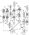
以下、本発明の一実施の形態について、図を用いて説明する。図1は、本発明の超音波−磁気共鳴複合医療装置(以下、US−MR複合医療装置と略称する。)の一実施の形態のブロック構成図である。
【0026】
まず、超音波医療装置の部分から説明する。超音波プローブ1は、撮像プローブ2と治療プローブ3が一体に形成され、プローブ支持部4を手で持って操作するように形成されている。撮像プローブ2は、周知の超音波診断装置に用いられるものと同様、例えばコンベックス型のように、複数の振動子を一列又は複数列に配列して形成されている。治療プローブ3は、複数の振動子を撮像プローブ2の両側に分けて、凹状の曲面を形成するように対称的に配列して形成されている。本実施形態では、撮像プローブ2と治療プローブ3の配列方向を直交させているがこれに限られるものではない。
【0027】
治療プローブ3には、治療パルス発生回路11で発生された超音波パルスが、治療波収束回路12と増幅器13を介して供給される。つまり、治療波収束回路12において各振動子に供給する超音波を適宜遅延させることによって、治療プローブ3から射出される超音波ビームの収束点(焦点)を所望の位置に制御するとともに、増幅器13によって高エネルギの駆動パルスに変換して各振動子に供給される。
【0028】
一方、撮像プローブ2には、撮像パルス発生回路21から発生された撮像用の超音波パルスが撮像波収束回路22においてフォーカス処理され、増幅器23において増幅された後、送受分離器24を介して供給される。撮像プローブ2により生体内から受信された超音波の受信信号は、送受分離器24を介して増幅器25に導かれて増幅された後、超音波(US)信号処理部26において整相処理される。超音波(US)画像生成部27は、US信号処理部26から出力される受信信号に基づいて超音波断層像を生成する。生成された断層像はUSモニタ28に表示される。これらの治療パルス発生回路11、治療波収束回路12、撮像パルス発生回路21、撮像波収束回路22、US信号処理部26、US画像生成部27は、コンピュータにより形成されるUS制御部30の指令によって制御される。また、操作者は、操作器31から制御部30に指令を入力するによって、各種の診断条件や治療条件を設定できるようになっている。
【0029】
次に、磁気共鳴撮像(MRI)装置の部分について説明する。MRI装置は、MR装置本体41と、MR装置本体41を制御するMR制御部42と、MR制御部42に指令を入力するMR操作器43と、MR装置本体41から出力される核磁気共鳴信号を処理するMR信号処理部44と、処理された核磁気共鳴信号に基づいてMR画像を再構成するMR画像生成部45と、再構成されたMR画像を表示するMRモニタ46とを有して構成されている。
【0030】
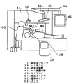
MR装置本体41は、図2に示すいわゆるオープンタイプのMRI装置を適用するのが好ましい。図示例は、垂直磁場方式の永久磁石型MRI装置である。図4を用いて、典型的なMR装置本体の概念を説明する。MR装置本体は、被検体401の周囲に静磁場を発生する磁石402と、この静磁場空間に傾斜磁場を印加する傾斜磁場コイル403と、この領域に高周波磁場パルスを印加するRFコイル404と、被検体401が発生するNMR信号を検出するRFコイル405を有して構成されている。傾斜磁場コイル403は、X、Y、Zの3軸方向の傾斜磁場コイルで構成され、傾斜磁場電源409からの信号に応じてそれぞれ傾斜磁場を発生する。RFコイル404はRF送信部410から供給される高周波磁場パルスによって高周波磁場を発生する。図2のオープン型のMRI装置本体41も、同様の機能を有する。そして、RFコイル405により受信される核磁気共鳴信号は、図1のMR信号処理部44に入力され、傾斜磁場電源409とRF送信部410は、図1のMR制御部42により制御される。MR制御部42は、撮像シーケンスに従ってMR装置本体41を駆動制御して所望のMR断層像を撮像するようになっている。
【0031】
次に、本発明の特徴に係る超音波医療装置とMRI装置の協調制御装置について説明する。協調制御装置は、超音波プローブの位置及び姿勢を検出する位置検出装置を含んで構成される。位置検出装置(例えば、Northern Digital Instrument 社のPOLARIS(商品名)を適用する。)は、超音波プローブ1に固定された検出ポインタ51と、MR装置本体41に固定された基準ポインタ52と、赤外線カメラ2個を備えた複眼カメラ53と、プローブ位置演算手段54とを有して構成される。
【0032】
位置検出装置としては、アクティブ型とパッシプ型があり、アクティブ型の検出ポインタ51と基準ポインタ52は、それぞれ少なくとも3個の赤外線発光ダイオードをマーカとし、そのマーカを例えば3角形の頂点に位置させて支持体に固定して形成される。バッシプ型の場合、検出ポインタ51と基準ポインタ52はそれぞれ少なくとも3個の反射球(例えば、直径10mm)をマーカとし、そのマーカを例えば3角形の頂点に位置させて支持体に固定して形成される。そして、複眼カメラ51に発光ダイオードを取り付けて形成される。
【0033】
複眼カメラ51は、連続的に検出ポインタ51と基準ポインタ52を受像し、受像データをプローブ位置演算手段54に出力する。プローブ位置演算手段54は、それぞれのマーカの3次元位置をリアルタイムで検出し、これに基づいて検出ポインタ51の6次元の動きを検出する。検出した6次元の動きを出力表示することもできる。位置の計測精度は、アクティブ型及びパッシブ型とも同等(例えば0.35mm)であり、また表示切り替え速度は20〜60Hzである。パッシブ型はポインタに電源を供給するラインが不要となるため使い勝手が良い。
【0034】
プローブ位置演算手段54により検出された検出ポインタ51の6次元の動き、つまり検出ポインタ51の位置及び姿勢の検出データは、協調制御手段55に入力される。協調制御手段55は、後述するように、US制御部30から超音波プローブ1の焦点深度を取り込み、検出ポインタ51の位置及び姿勢の検出データに基づいて、その焦点位置を通る断層面を設定し、MR制御部42に出力する。この時の断層面の方向は、超音波プローブ1の断層面の方向に一致させても良く、また術者の指定する任意の方向に設定することができる。
【0035】
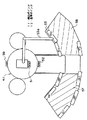
このような位置検出装置を、オープン型MRI装置を用いたUS−MR複合医療装置に適用する場合、図2及び図3に示す配置構成が好ましい。すなわち、基準ポインタ52はMR装置本体41のガントリー41aの正面及び裏面に固定する。これにより、基準ポインタ52の座標系を静磁場のMR座標系に一義的に一致させることができる。複眼カメラ53は、ガントリー41aの頂部中心に回動自由に支持されたアームに連結された複数のアームからなる支持アーム53aに吊り下げて設ける。これにより、複眼カメラ53は、図3の平面図に示すように、ガントリー41aを中心とした円弧状の領域内の任意の位置に移動させることができる。
【0036】
図3において、術者100は把持した超音波プローブ1に検出ポインタ51が固定して設けられている。超音波プローブ1は超音波装置本体33に接続され、術者100の操作により被検体401の所望の部位の断層撮像又は治療をすることができるようになっている。また、MRモニタ46はMR装置本体41のガントリー頂部に回動自由に支持された複数のアームからなる支持アーム46aに吊り下げて設けられている。
【0037】
このように構成されるUS−MR複合装置の協調制御手段55の詳細構成を、動作例とともに次に説明する。
(超音波治療の実施の形態)
図2に示すように、術者100が超音波プローブ1を手に持ち被検体401にあてる。この場合、超音波プローブ1を非磁性の支持部材で支持し固定するようにしても良い。そして、術者100は、超音波プローブ1の位置や傾きを操作して、被検体401の撮影断面を決めて超音波撮像を開始する。これにより、USモニタ28に断層像が表示される。術者100は超音波プローブ1の位置と姿勢を変えながら治療対象の病変部を探す。このとき、プローブ位置演算手段54により複眼カメラ53から出力される受像データに基づいて、検出ポインタ51の位置と姿勢が検出される。
【0038】
協調制御手段55は、US制御部30からその時の撮像プローブ2の焦点深さを取り込み、検出ポインタ51の位置と姿勢及び焦点深さとから、術者が認識した病変部の3次元位置をMR座標系について算出する。そして、その病変部を含み、例えば超音波断層像と同じ方向の断層面のMR像を撮像するようにMR制御部42に指令を出力する。MR撮像断面は、超音波プローブ1又はUS操作器31等に設けた操作スイッチにより、超音波プローブ1と平行な断面、超音波ビームと同一な面、又はそれらの断面に垂直な断面を選択できる。これにより、術者は、症例や病変部位に応じて断面を切り替えながらモニタできる。
【0039】
MR制御部42は、撮像シーケンスの断層面を協調制御手段55から指令された設定断層面に決定し、MR装置本体41を駆動制御する。これにより、MRモニタ46に術者100が認識した病変部を含む断層像が表示される。通常、病変部は直径2〜3cmの球状又は楕円球状である。このMR撮像処理は、超音波プローブ1の動きに追従してリアルタイムで行なわれる。つまり、術者100は超音波プローブ1を動かすことによって、MR断層面の設定を自由に、かつ簡単に行なえる。
【0040】
MRIの撮像シーケンスは、例えばフロロスコピィシーケンスを適用し、協調制御手段55から出力される設定断面の指令は、例えば0.5秒以内ごとに更新され、MRI断層像に反映される。なお、撮像シーケンスは、周知のTRSGシーケンス、SGシーケンス、マルチショットEPIなどのフロロスコピィ用シーケンスを適用することができる。これらのシーケンスでは、0.5〜4秒ごとに画像を更新できる。なお、MR画像の典型的なスライス厚さは8mm程度である。
【0041】
このようにして、術者100が超音波プローブ1を動かすことによって、病変部を含むMR断層像がMRモニタ43に表示される。一方、このMR断層像によれば、病変部の体表面からの深さを精度よく計算によって求めることができる。そこで、MR制御部42は超音波プローブ1の断層面を基準にして、体表面から病変部までの距離を演算して協調制御手段55に出力する。協調制御手段55は、その距離を治療用超音波ビームの収束点データとしてUS制御部30に転送する。
【0042】
US制御部30は、治療用超音波ビームの収束点データに従って治療波収束回路12に指令を出し、治療プローブ3から照射される超音波ビームの収束位置を制御する。すなわち、治療プローブ3の振動子(圧電素子)は、図5に示すように、曲率Rの円弧状に配置され、収束点の距離Fにおいて超音波ビームが収束する。この距離Fは被検体401の内部であり、例えば病変部に調整される。この収束点の距離Fは、治療波遅延回路22において各振動子に供給する超音波のタイミング時間を変えることにより調整できる。
【0043】
この状態で、術者100は、超音波プロープ1の動きを止め、収束超音波を病変部に照射し、局部的な加熱治療を行なう。これにより、簡単に治療用超音波ビームの収束点を病変部に合わせて、その部位を加熱することにより治療できる。治療プローブ3から超音波ビームが照射されたことは、US制御部30又は協調制御手段55を介してMR制御部42に伝達される。
【0044】
これに応答して、MR制御部42は、同一断面について例えばT1強調画像もしくはT2強調画像の撮像シーケンスを実行させるとともに、MR信号処理部44とMR画像生成部45に指令を送って、病変部を含む領域の温度分布変化を求めて温度分布画像を生成させる。その温度分布画像は、MRモニタ46に表示される。本実施形態の場合は、T1強調画像もしくはT2強調画像を2〜7秒程度で繰り返し撮像することが好ましく、撮影マトリクスは128×128ないし256×256が一般的である。これにより、術者100は、超音波治療の効果を画像上で容易に確認することができる。その結果、不要な部分に治療を施すことを避けることができ、また治療により加熱された部位の冷却を確認して隣接病変部の治療を順次施して、病変部の治療を漏れなく施すことができる。また、治療後に、MRI撮像を施し、病変部(例えば、腫瘍)が消滅したか否かを判断することもできる。
【0045】
上述したように、本実施の形態の超音波治療法によれば、超音波医療装置の操作性の良さを失うことなく、MRI装置の高分解能と、距離計測の精度と、温度計測などの機能を有機的に利用して、使い勝手の良い治療装置を実現できる。
【0046】
また、図3に示したように、複眼カメラ53は、MR装置本体41の静磁場発生領域の中心から1〜1.5m離れた位置に、支持アーム53aで吊り下げ、自由に向きや位置を変えられるようにすることが好ましい。これにより、術者の操作の妨げになることを回避できるとともに、検出ポインタ51及び基準ポインタ52が術者や手術機器の陰にならないように、複眼カメラ53を移動させることができる。つまり、図中に示した2つの扇形領域57、58が、複眼カメラ53から検出ポインタ51と基準ポインタ52の双方を安定に検出できる範囲である。扇形領域57,58の半径は、170〜293 c mの範囲が適当である。また、複眼カメラ53の高さは、95〜107cm程度が適当である。この範囲で、カメラが稼動するように、支持アーム53aを形成する。また、複眼カメラ53からプローブ位置演算手段54に送る受像データの更新周期は、2〜20セット/秒程度が好ましい。この受像データは、複眼カメラ53から光ファイバーケーブルにより伝送することにより、MR装置のノイズの混入を防ぐことができる。
【0047】
なお、図3では、MR装置本体のベッドの一方のサイドのみについて、複眼カメラ53の位置を検討したが、非対称2本柱構成のMRI装置なので術者はベッドの反対側から被検体にアクセスもできる。その場合は、複眼カメラ53をベッドの反対側に移動することができる。これに対応させて、上述の基準ポインタ52とは別に、ベッドの反対側に基準ポインタ59を設置しておくのが好ましい。この場合、基準ポインタ52と59の3つのマーカ(反射球)の相対位置を、異なる配置にすることが好ましい。これにより、複眼カメラ53は、どの基準ポインタを受像している識別できる。これに応じて、プローブ位置演算手段54は、識別した基準ポインタの位置を自動的にメモリーから読み出し、MR座標系における撮影断面データを自動的に求めることができる。
【0048】
ところで、図1の実施形態の超音波治療装置において、撮像プローブ2と治療プローブ3の双方を備えた超音波プローブ1を用いる例を示した。しかし、撮像装置としてMRI装置が備えられているので、撮像プローブ2を省略することも可能である。つまり、図1の超音波プローブ1を治療プローブ3のみ備えたものとし、これに合わせて撮像用の機能を省略する。そして、位置検出装置により検出した超音波プローブ1の位置及び姿勢に従ってMRI装置によりMR断層像をMRモニタ46(又は、USモニタ28)に表示する。術者は専らMR像に基づいて病変部を探り、治療したい病変部をMRモニタ46(又は、USモニタ28)上でマーカなどにより指定する。これにより、MR制御部42は指定されたマーカの3次元位置、特に超音波プローブ1が当接された体表面から病変部までの距離を演算して協調制御装置55に送出する。協調制御手段55は、体表面から病変部までの距離に基づいて、超音波プローブ1の収束位置を演算してUS制御部30に送る。これに応じて、US制御部30は、治療波収束回路12に指令を送り、治療超音波ビームの収束位置を病変部に合わせるようにすることができる。
【0049】
また、治療プローブ3の超音波ビームの強度を撮像レベルに下げて、図1の実施の形態と同様に構成することもできる。この場合は、超音波撮像の画像の解像度は落ちるが、病変部の位置を探るには十分な場合がある。
(超音波3次元画像の生成法)
超音波の撮像プローブを用いて術者が所望の超音波(US)3次元像を撮像する一方で、その撮像プローブの動きに伴う位置と姿勢の変化を検出してUS3次元像に対応するMR3次元像を撮像し、それらの3次元像の優れた点を組み合わせて、診断に有意な3次元像を作成して術者に提供できる。例えば、MRIの3次元画像データから各組織の境界部を検出し、その境界座標を求めてUS像の3次元画像の境界を形成することができる。
【0050】
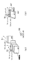
図6及び図7を参照して、具体的な実施形態を説明する。図6は、US3次元像を撮像する際の超音波プローブ1の操作法を説明する図である。同図(a)に示すように、超音波プローブ1を図示していない被検体の体表面に沿ってほぼ平行に移動させながら、US像を複数の3次元位置(xi、yi、zi)(但し、iは1〜nの自然数)で、複数枚a1〜anの撮像を実行する。これにより撮像された各US像データはメモリに記憶される。この場合、プローブ位置演算手段54は、超音波プローブ1に固定された検出ポインタ51と、基準ポインタ52の受像データに基づいて、US断層像の3次元位置及び方向(以下、US断層像位置データと称する)をMR座標系に変換し、協調制御手段55を介してUS制御部30に転送する。US制御部30は、US断層像位置データを各US断層像に対応付けて記憶させる。なお、図6(b)に示すように、超音波プローブ1の位置を変えずに姿勢(傾き角度)を変えて3次元撮像する場合も同様である。
【0051】
一方、MRI装置は、周知のT1強調画像又はT2強調画像を撮像する。撮像シーケンスは、例えば、ファーストスピンエコー法やグラディエントエコー法を用いる。画素数は、例えば、256×256×256とする。この場合、典型的な空間分解能は1mmである。MR画像では、T1値又はT2値が異なることにより、臓器(組織)ごとのコントラストが異なっている。このことを利用して、公知のリージョングローイング法によって臓器を抽出することができる。つまり、組織ごとに画素値が異なることを利用して、MR画像から特定の臓器の部分を抽出する。これにより抽出した臓器又は組織の辺縁の画素番号を得る。この画素番号は、MR座標系に一対一で対応付けることができる。
【0052】
ところで、プローブ位置演算手段54により、US画像上の画素位置(番号)とMR座標系の画素番号とを一対一で対応付けることができる。したがって、MR画像上で抽出した臓器の辺縁が、US画像上のどの位置にあたるかを決定できる。
【0053】
例えば、図7(a)に示すように、被検体401の3次元領域71について超音波プローブ1を操作して撮像を実行し、同図(b)に示すUS3次元像を取得したとする。3次元領域71の基準点71aを設定する。一方、MRI装置により同一の領域71について撮像し、同図(b)に示すMR3次元像を取得する。
【0054】
そして、MR3次元像に基づいて、断層像表示指定ライン72を設定して任意のスライス断面を決める。これに基づいて、断層像表示指定ライン72で設定されたUS断層像とMRI断層像を画像化する。これにより、臓器73を含む断層像が表示モニタに表示できる。
【0055】
この表示において、例えば、US断層像をグレースケールで表示する。そして、MR断層像の臓器73の辺縁画像を異なる色(例えば、黄色)で、US断層像に半透明で重ねて表示する。これにより、超音波断層像では判別できなかった臓器の輪郭うを、観察者は容易に識別できるようになる。したがって、観察者は、臓器の輪郭の他、超音波撮像特有の情報(例えば、局所部位の弾性率、血流によるドップラー現象による情報)等を、同一画面上で観察することができ、診断等に便利である。
【0056】
また、US画像の臓器73の内側の画素のみを抽出して得られるUS3次元画像を、パーシャルMIP(Maximum Intensity Method:最大値)処理、あるいはパーシャルボリュームレンダリング処理し、対象とする臓器内のUS画像を3次元情報を含む形で表示することができる。これによれば、US画像における生体深部での信号値が低いデータや、皮膚近傍の高信号のデータを除去することができ、それらのノイズ分を除去して画質を向上することが期待できる。なお、MIP処理、あるいはパーシャルボリュームレンダリング処理は、MRIやCT画像に対して広く行なわれている画像処理である。
(その他、変形例)
図4に示したRFコイル405としては、種々の形状のものが開発されており、撮影部位、撮影目的に応じて使い分けられる。例えば、表面コイルは、局所的な部位を高感度で撮影するRFコイルである。従来、局所コイルは、耳、顎関節、四肢の関節など、小視野で高画質が要求される部位の撮影用に用いられている。また、複数の小型表面コイルを隣接して配置し、高感度と視野拡大を図ったマルチプルアレイコイル(フェイズドアレイコイルとも呼ばれる)も開発されている。通常の頭部撮影や腹部撮影には、視野が広く感度分布が比較的均一なボリュームコイルが使われる。これには、マルチプルエレメントレゾネータ、スロッテドチューブレゾネータ、ソレノイドコイルが公知である。
【0057】
手術や穿刺、経皮的治療に使われるいわゆるI−MRI(Interventiona1 MRI,Intraoperative MRI)は、オープンタイプのMRI装置が使用される。オープンMRIには、ダブルドーナツ型や、C型、非対称2本支柱型がある。ダブルドーナツ型は、水平磁場を発生するドーナツ型磁石を2個、隙間を空けて並べた構造で、隙間の間で被検体の撮影を行う。C型と非対称2本支柱型は、ハンバーガー型の磁石で上下方向の静磁場を発生する。最もオープン性があるのは、非対称2本支柱型で、被検体の左右方向と頭頂部側の3方向からのアクセスが可能である。
【0058】
MRIの撮影断面をインタラクティブに設定する技術は、インタラクティブスキャンコントロールとして公知である。すなわち、MRIを用いた手術時の穿刺モニタリングや心臓撮影などでは、リアルタイムに撮影断面を任意に設定したい要望があり、これに対応する技術開発も行われつつある。撮影断面を任意に選択する手法として、グラフィカルユーザーインターフェースにMRI画像を表示して、画面上のボタンをクリックして、次の撮影断面を決定する例がある(Magnetic Resonance in Medicine:Rea1-time interactive MRl on a conventional scanner; AB. Kerr他、38巻、pp. 355-367(1997))。また、3次元マウスを使うなどの手法がある(USP-5512827)。また、位置決定デバイスを使ってMRIの撮影断面を決定する装置が開示されている(USP-5365927:位置センサの情報を使ってMRIの撮影を行なう)、(USP-6026315;2個の赤外線カメラと3個の反射球からなるポインタを使って撮影断面を決定する)。
【0059】
超音波装置において、収束超音波を照射し、生体内を加熱する技術は公知である。例えば、特開2001-46387号公報には、被検体内の治療部位を超音波画像で常にモニタしながら治療する超音波治療アプリケータが開示されている。
【0060】
また、生体内の加熱部位をモニタする技術は、MRIにより可能であることは公知である。つまり、MRIでは、生体内の温度をモニタでき、この機能を活用してレーザ照射治療のモニタや、RF(Radio Frequency)アブレーションのモニタをするようになりつつある。
【0061】
温度モニタの方法は、各種の提案がされているが、下記の信号強度法と位相法(PPS法:proton phase shift)が、多く検討されている。
(1)信号強度法:被検体の温度が変化するとT1値が変化することが知られている。また、レーザ蒸散法のように、局所的に高温度になる場合、生体のT2値や水分含有量が変化し信号値が変化する。この変化から、生体内の温度変化を定性的に把握できる。
(2)位相法:プロトンの共鳴周波数は、温度に比例する。その温度係数Cは−0.01(ppm/℃)である。GrE系シーケンスで生体の加熱前と加熱後に撮影した2つの画像の位相差分を求めると、差分後の位相θ(i,j)(rad)(i、jは画素番号)は、次式(1)で表わせる。
【0062】
θ(i,j)=γ・Bo・C・ΔT(i、j)・τ (1)
ここで、γは磁気回転比、Boは静磁場強度、ΔT(i、j)は加熱前後の生体の温度変化、τはエコー時間である。(1)式から、次式(2)により温度変化画像が得られる。温度変化画像の表示には、2次元カラーマップが使われている。
【0063】
ΔT(i、j)=θ(i,j)/(γ・Bo・C・τ) (2)
一方、MRAの血管撮影(MRA: MR angiography)では、位相画像から3次元的な構造を表示する方法として、最大投影値法(MIP: maximum intensity projection)などが、使われており、主に利用されている。また、最近では、ボリュームレンダリング(VR: volume rendering)法も試みられている。
【0064】
温度画像の公知例としては、例えば、著者:Paul Steiner MD, Rene Botnar PhD,Benjamin Dubno MD, Gesine G Zimmermann MD,G Scott Gazelle MD, Jorg F Debatin MD.題名:Radio-frequency-induced thermoablation: monitoring with T1-weighted and proton-frequency-shift MR imaging in an interventional 0.5-T environment.雑誌名:Radiology 206, 803-810,March (1998)がある。
【0065】
【発明の効果】
以上述べたように、本発明によれば、超音波医療装置とMRI装置の長所を組み合わせ、操作性及び機能性に優れた複合医療装置を実現できる。
【図面の簡単な説明】
【図1】本発明の超音波−磁気共鳴複合医療装置の一実施の形態のブロック構成図である。
【図2】本発明の超音波−磁気共鳴複合医療装置の一実施の形態の外観構成図である。
【図3】図2の超音波−磁気共鳴複合医療装置の一実施の形態の位置検出装置の設定法を説明する平面図である。
【図4】磁気共鳴装置の典型的な一例を説明する構成図である。
【図5】治療プローブの収束点の説明図である。
【図6】超音波撮像における3次元撮像の操作を説明する図である。
【図7】超音波撮像装置とMRI装置の複合画像を生成する例を説明する図である。
【符号の説明】
1 超音波プローブ
2 撮像プローブ
3 治療プローブ
4 プローブ支持部
12 治療波収束回路
13 撮像波収束回路
26 US信号処理部
27 US画像生成部
28 USモニタ
30 US制御部
41 MR装置本体
42 MR制御部
44 MR信号処理部
45 MR画像生成部
46 MRモニタ
51 検出ポインタ
52 基準ポインタ
53 複眼カメラ
54 プローブ位置演算手段
55 協調制御手段[0001]
BACKGROUND OF THE INVENTION
The present invention belongs to a technique of an ultrasonic-magnetic resonance composite medical device that combines ultrasonic imaging and / or ultrasonic therapy and magnetic resonance imaging.
[0002]
[Prior art]
The ultrasonic imaging apparatus irradiates a subject with ultrasonic waves from a probe, receives a reflected signal of an ultrasonic wave generated from the inside of the subject, and the inside of the subject is a two-dimensional or three-dimensional image based on a difference in acoustic characteristics. For diagnosis and treatment, for example, by imaging information such as blood flow velocity. On the other hand, a magnetic resonance imaging apparatus (MRI apparatus) excites specific nuclei such as hydrogen (proton) and phosphorus which are main substances constituting a subject by applying a high-frequency magnetic field pulse to the subject in a static magnetic field, The nuclear magnetic resonance signal generated thereby is received, and for example, the proton density distribution and the spatial distribution of the relaxation phenomenon of the excited state are imaged two-dimensionally or three-dimensionally, or various biological information is imaged for diagnosis and treatment. .
[0003]
These ultrasonic imaging apparatuses and MRI apparatuses are widely used as medical apparatuses, and developments in application fields are progressing. For example, monitoring of invasive devices such as catheters, monitoring of therapeutic instruments that perform treatment by inserting laser fibers or microwave electrodes into the lesion, techniques for observing the therapeutic effects, and focused ultrasound from outside the subject Ultrasound treatment, in which heat treatment is performed by irradiating the lesion area, etc. have been proposed.
[0004]
[Problems to be solved by the invention]
By the way, in an ultrasonic medical device, an ultrasonic probe for imaging or treatment can be held by hand and applied to the body surface of a subject, and a tomographic image of a part to be observed can be arbitrarily selected while moving or tilting the probe. In addition, since the direction of the therapeutic ultrasonic beam can be adjusted to the lesion site, it is extremely excellent in operability.
[0005]
However, since ultrasonic imaging requires operation by placing the ultrasonic probe on the outer surface of the subject, the operation range of the position and tilt of the ultrasonic probe is limited, and a tomographic image at an arbitrary position and direction is captured. For example, there is a drawback that a tomographic image of a blood vessel at a desired site cannot be obtained.
[0006]
In addition, the ultrasonic treatment is a so-called non-invasive treatment in which treatment is performed by irradiating a living body with an ultrasonic beam stronger than imaging from an ultrasonic probe and heating the affected part, so that the burden on the patient is reduced. There is an advantage of less.
[0007]
However, since ultrasonic imaging cannot accurately measure the position (especially depth) of a lesioned part, a technique for accurately matching the convergence position of a high-intensity therapeutic ultrasound beam to the lesioned part becomes a problem. In other words, even if the imaging probe can be moved or tilted by hand to find the lesion, it is difficult to measure the three-dimensional position of the lesion, particularly the depth of the lesion. The depth cannot be adjusted accurately.
[0008]
On the other hand, when a lesion is treated with a laser or microwave, since the laser fiber or microwave electrode is in contact with the lesion, for example, the tip of the laser fiber is included as an imaging section by MRI imaging or the like. Thus, the treatment site is included in the imaging section.
[0009]
In short, it is relatively easy to set the imaging section of MR imaging on the image, but in the case of ultrasonic therapy, the treatment site and the ultrasonic probe are separated from the inside and outside of the subject. Cannot be applied as is. Therefore, it is necessary to determine the convergence position of the ultrasonic beam by some method, set the convergence position on the MR image or the like by any method, and take an imaging section including the position by MRI.
[0010]
However, since the depth of convergence of the ultrasound beam varies depending on the radius of curvature of the treatment probe, the ultrasound delay time between each transducer, the ultrasound frequency, etc. Mistakes and highly skilled knowledge are necessary, and it is a complicated task for a surgeon who performs treatment and diagnosis.
[0011]
Similarly, in ultrasound imaging, since the resolution of the image depends essentially on the wavelength of the ultrasound, the boundary of the tissue becomes unclear, so it is necessary to accurately measure the boundary and size of the lesion. May be a problem for treatment. In addition, establishment of a technique for measuring the effect of treatment on a site subjected to ultrasonic treatment is desired.
[0012]
On the other hand, the MRI apparatus has a high contrast resolution. Currently, a resolution of 256, 512, etc. is used, and a resolution of 1024 has been tried in part, so that the boundary of the tissue can be clearly imaged. Further, the MRI apparatus can arbitrarily set the position and orientation of the imaging cross section as compared with the ultrasonic imaging, and can capture a desired vascular tomographic image. In addition, in view of the fact that the T1 relaxation time and the T2 relaxation time correlate with the temperature, or the resonance frequency correlates with the temperature, it is possible to measure the temperature change of the specific part by measuring them. Different biological information can be obtained.
[0013]
However, the imaging section in the case of the MRI apparatus is inferior in operability compared to ultrasonic imaging, for example, an operation for setting a parameter related to the imaging section of the imaging sequence must be performed on the image.
[0014]
Accordingly, an object of the present invention is to realize a composite medical apparatus that is excellent in operability and functionality by combining the advantages of an ultrasonic medical apparatus and an MRI apparatus.
[0015]
[Means for Solving the Problems]
The present invention solves the above problems by the following means.
[0016]
The present invention is intended to enhance functionality by combining an ultrasonic medical apparatus and a magnetic resonance imaging apparatus while maintaining the operability of the ultrasonic medical apparatus. That is, the ultrasonic probe is driven to irradiate the subject with imaging ultrasonic waves, and the US control means for processing the ultrasonic signal received by the ultrasonic probe, and the reception-processed ultrasonic signal An ultrasonic medical apparatus having a US image generation means for generating a tomographic image based on it and an imaging sequence for applying a gradient magnetic field and a high frequency pulse to a subject placed in a static magnetic field according to a set tomographic plane A magnetic resonance imaging apparatus comprising: an MR control means for performing the imaging sequence; and an MR image generation means for generating a tomographic image based on a nuclear magnetic resonance signal generated from the subject by execution of the imaging sequence. Basic. In this case, the display means for displaying the images generated by the US image generation means and the MR image generation means may be provided individually or shared.
[0017]
In particular, the present invention receives a detection pointer of a position and orientation fixed to an ultrasonic probe, a reference pointer fixed to an apparatus main body of the magnetic resonance imaging apparatus, the detection pointer, and the reference pointer. A compound eye camera, and probe position calculation means for converting the position and orientation of the ultrasonic probe into a coordinate system (hereinafter referred to as MR coordinate system) of the MRI apparatus based on image data received by the compound eye camera. To do. That is, since the reference pointer is fixed to the MRI apparatus main body, the coordinate system of the reference pointer and the MR coordinate system of the static magnetic field space where the subject is placed uniquely match. Therefore, the MR control means can recognize the position and orientation of the ultrasonic probe in the MR coordinate system by the probe position calculation means.
[0018]
As a result, for example, by acquiring the focal position of the imaging ultrasonic beam from the US control unit, a cross section in an arbitrary direction including the focal position can be easily set as the imaging cross section. In this case, the set tomographic plane of the MR image is determined based on the position and orientation of the ultrasonic probe converted by the probe position calculating means and the focal position of the ultrasonic probe output from the US control means. can do. In addition, the determined set fault plane Provide cooperative control means for outputting to the MR control means be able to . This cooperative control means can be realized by a personal computer.
[0019]
In particular, when a lesion is detected by operating an ultrasound imaging probe, the tomographic plane direction of the US tomogram is determined from the position and orientation of the imaging probe at that time, and the depth of the lesion is determined by the focal position of the imaging probe at that time. The three-dimensional position of the lesion can be obtained. That is, the MR control means executes the imaging sequence for the set tomographic plane passing through the lesion site that is the focal position of the imaging probe. And MR control means detects the position of a lesion part accurately based on the acquired MR tomogram. Next, the position of the convergence point of the therapeutic ultrasound beam is calculated from the MR tomographic image data based on the detected position of the lesioned part, and the calculated convergence point position is output to the US control means. Thus, the US control means controls the convergence point of the therapeutic ultrasonic beam. As a result, a therapeutic ultrasonic beam can be accurately irradiated onto the lesioned portion, so that the operability of the treatment is improved. In addition, since the MR tomographic image is switched following the position and inclination of the treatment probe, it is only necessary to adjust the position and inclination of the treatment probe so that the lesion is displayed on the MR image. A therapeutic ultrasound beam can be irradiated.
[0020]
Further, the MR control means executes an imaging sequence for the set tomographic plane passing through the lesion, detects a mark representing a treatment point input and set in the MR tomographic image displayed on the display means, and executes the imaging sequence. The position of the convergence point of the therapeutic ultrasound beam may be calculated from the image data based on the position, and the calculated convergence point position may be output to the US control means.
[0021]
Further, the US control means controls the convergence point position of the therapeutic ultrasonic beam based on the input convergence point position of the therapeutic ultrasonic beam, and responds to a given command from the ultrasonic probe for therapeutic use. In accordance with this, the MR control means outputs the convergence point position of the therapeutic ultrasound beam to the US control means, and then captures a T1 or T2-weighted image for the tomographic plane including the convergence point. It is preferable to execute the sequence. Further, it is preferable that the MR control means measures a temperature change of the MR tomogram based on the image data of the T1 or T2 weighted image and displays a color mapping image on the display device according to the temperature change. Thereby, the surgeon can easily confirm the effect of the treatment.
[0022]
Further, while allowing an operator to observe a desired US tomographic image using an ultrasonic imaging probe, changes in the position and posture of the US tomographic image are obtained by detecting changes in position and posture associated with the movement of the imaging probe. The MR image of the same cross section can be taken in accordance with the position change of the US tomographic image.
[0023]
Specifically, the US control unit takes in the coordinate data of the position and orientation of the ultrasonic probe converted into the MR coordinate system output from the cooperative control unit, and MR coordinate data into the image data of the ultrasonic three-dimensional tomographic image. The MR control means executes an imaging sequence for imaging an MR three-dimensional image of a region corresponding to the ultrasonic three-dimensional tomographic image, and a specific tissue (for example, based on the picked-up MR three-dimensional image) And the image data relating to the boundary can be output to the display unit and displayed on the ultrasonic three-dimensional tomographic image. According to this, it is possible to complement an ultrasonic tomographic image with a poor resolution of the boundary of an organ or the like, and to clearly display the boundary of the organ with an MR image.
[0024]
Further, based on the boundary of a specific tissue such as an organ obtained in the same manner, the US control means extracts pixel data of an ultrasonic three-dimensional tomographic image within the boundary and displays it on the display means. You can also According to this, it is possible to remove a signal from a tissue other than the organ and to improve the image quality inside the organ.
[0025]
DETAILED DESCRIPTION OF THE INVENTION
Hereinafter, an embodiment of the present invention will be described with reference to the drawings. FIG. 1 is a block diagram of an embodiment of an ultrasonic-magnetic resonance composite medical device (hereinafter abbreviated as US-MR composite medical device) of the present invention.
[0026]
First, the ultrasonic medical device will be described. The ultrasonic probe 1 is formed so that an
[0027]
The
[0028]
On the other hand, an imaging ultrasonic pulse generated from the imaging
[0029]
Next, the magnetic resonance imaging (MRI) apparatus will be described. The MRI apparatus includes an MR apparatus
[0030]
The MR apparatus
[0031]
Next, a cooperative control apparatus for an ultrasonic medical apparatus and an MRI apparatus according to features of the present invention will be described. The cooperative control device includes a position detection device that detects the position and orientation of the ultrasonic probe. A position detection device (for example, POLARIS (trade name) of Northern Digital Instrument Co., Ltd. is applied) includes a
[0032]
As the position detection device, there are an active type and a passive type. Each of the active
[0033]
The
[0034]
The six-dimensional movement of the
[0035]
When such a position detection apparatus is applied to a US-MR combined medical apparatus using an open MRI apparatus, the arrangement configuration shown in FIGS. 2 and 3 is preferable. That is, the
[0036]
In FIG. 3, the
[0037]
A detailed configuration of the cooperative control means 55 of the US-MR composite apparatus configured as described above will be described below together with an operation example.
(Embodiment of ultrasonic therapy)
As shown in FIG. 2, the
[0038]
The cooperative control means 55 takes in the focal depth of the
[0039]
The
[0040]
For example, a fluoroscopic sequence is applied as the MRI imaging sequence, and the command of the set cross section output from the cooperative control means 55 is updated every 0.5 seconds, for example, and reflected in the MRI tomographic image. As the imaging sequence, a well-known TRSG sequence, SG sequence, multi-shot EPI, or other fluoroscopic sequence can be applied. In these sequences, the image can be updated every 0.5 to 4 seconds. A typical slice thickness of the MR image is about 8 mm.
[0041]
In this way, when the
[0042]
The
[0043]
In this state, the
[0044]
In response to this, the
[0045]
As described above, according to the ultrasonic therapy method of the present embodiment, functions such as the high resolution of the MRI apparatus, the accuracy of distance measurement, and the temperature measurement without losing the operability of the ultrasonic medical apparatus. It is possible to realize an easy-to-use treatment device by using organically.
[0046]
As shown in FIG. 3, the compound-
[0047]
In FIG. 3, the position of the
[0048]
By the way, the example using the ultrasonic probe 1 provided with both the
[0049]
In addition, the intensity of the ultrasonic beam of the
(Method for generating ultrasonic three-dimensional image)
While an operator images a desired ultrasonic (US) three-dimensional image using an ultrasonic imaging probe, MR3 corresponding to the US three-dimensional image is detected by detecting a change in position and posture associated with the movement of the imaging probe. A three-dimensional image can be taken and a superior point of these three-dimensional images can be combined to create a three-dimensional image significant for diagnosis and provided to the operator. For example, the boundary portion of each tissue can be detected from the three-dimensional image data of MRI, and the boundary coordinates can be obtained to form the boundary of the three-dimensional image of the US image.
[0050]
A specific embodiment will be described with reference to FIGS. 6 and 7. FIG. 6 is a diagram for explaining an operation method of the ultrasonic probe 1 when capturing a US three-dimensional image. As shown in FIG. 5A, the US image is moved to a plurality of three-dimensional positions (xi, yi, zi) (x) while moving the ultrasonic probe 1 substantially parallel along the body surface of the subject not shown. However, i is a natural number of 1 to n), and imaging of a plurality of sheets a1 to an is executed. Thus, each US image data imaged is stored in the memory. In this case, the probe position calculation means 54 determines the three-dimensional position and direction of the US tomographic image (hereinafter referred to as US tomographic image position data) based on the
[0051]
On the other hand, the MRI apparatus captures a known T1-weighted image or T2-weighted image. For example, a fast spin echo method or a gradient echo method is used for the imaging sequence. The number of pixels is, for example, 256 × 256 × 256. In this case, a typical spatial resolution is 1 mm. In the MR image, the contrast for each organ (tissue) is different due to the different T1 value or T2 value. By utilizing this fact, an organ can be extracted by a known region growing method. That is, a specific organ portion is extracted from the MR image using the fact that the pixel values differ for each tissue. As a result, the pixel numbers of the edges of the extracted organ or tissue are obtained. This pixel number can be associated with the MR coordinate system on a one-to-one basis.
[0052]
By the way, the probe position calculation means 54 can associate the pixel position (number) on the US image with the pixel number of the MR coordinate system on a one-to-one basis. Therefore, it is possible to determine which position on the US image the edge of the organ extracted on the MR image is.
[0053]
For example, as shown in FIG. 7A, it is assumed that imaging is performed by operating the ultrasonic probe 1 on the three-
[0054]
Based on the MR three-dimensional image, a tomogram display designation line 72 is set to determine an arbitrary slice cross section. Based on this, the US tomographic image and the MRI tomographic image set in the tomographic image display designation line 72 are imaged. Thereby, a tomographic image including the
[0055]
In this display, for example, the US tomographic image is displayed in gray scale. Then, the marginal image of the
[0056]
Further, a US three-dimensional image obtained by extracting only the pixels inside the
(Other variations)
The
[0057]
An open type MRI apparatus is used for so-called I-MRI (Interventiona1 MRI, Intraoperative MRI) used for surgery, puncture, and percutaneous treatment. Open MRI includes a double donut type, a C type, and an asymmetric two-post type. The double donut type has a structure in which two donut-shaped magnets that generate a horizontal magnetic field are arranged with a gap therebetween, and the subject is imaged between the gaps. The C type and the asymmetric two-post type generate a static magnetic field in the vertical direction with a hamburger type magnet. The most open type is an asymmetrical two-column type, which can be accessed from the left and right directions of the subject and the three directions on the parietal side.
[0058]
A technique for interactively setting an MRI imaging section is known as interactive scan control. That is, in puncture monitoring at the time of surgery using MRI, cardiac imaging, and the like, there is a demand to arbitrarily set an imaging section in real time, and technical development corresponding to this is being performed. There is an example in which an MRI image is displayed on the graphical user interface and the next section is determined by clicking a button on the screen as a method for arbitrarily selecting the section (Magnetic Resonance in Medicine: Rea1-time interactive) MRl on a conventional scanner; AB. Kerr et al., 38, pp. 355-367 (1997)). Another method is to use a 3D mouse (USP-5512827). In addition, an apparatus for determining an MRI imaging cross section using a position determination device is disclosed (USP-5365927: MRI imaging is performed using information from a position sensor), (USP-6026315; two infrared cameras) And the cross section is determined using a pointer consisting of three reflecting spheres).
[0059]
A technique of irradiating convergent ultrasonic waves and heating the inside of a living body in an ultrasonic device is known. For example, Japanese Patent Laid-Open No. 2001-46387 discloses an ultrasonic therapy applicator that treats a treatment site in a subject while constantly monitoring the treatment site with an ultrasonic image.
[0060]
In addition, it is known that a technique for monitoring a heated part in a living body is possible by MRI. That is, in MRI, the temperature in a living body can be monitored, and this function is used to monitor laser irradiation treatment and RF (Radio Frequency) ablation.
[0061]
Various proposals have been made for methods of temperature monitoring, but the following signal intensity method and phase method (PPS method: proton phase shift) have been studied extensively.
(1) Signal intensity method: It is known that the T1 value changes when the temperature of the subject changes. In addition, when the temperature is locally high as in the laser transpiration method, the T2 value of the living body and the water content change, and the signal value changes. From this change, the temperature change in the living body can be grasped qualitatively.
(2) Phase method: The resonance frequency of proton is proportional to temperature. The temperature coefficient C is −0.01 (ppm / ° C.). When the phase difference between two images taken before and after heating the living body in the GrE system sequence is obtained, the phase θ (i, j) (rad) (i and j are pixel numbers) after the difference is expressed by the following formula (1 ).
[0062]
θ (i, j) = γ · Bo · C · ΔT (i, j) · τ (1)
Here, γ is the magnetic rotation ratio, Bo is the static magnetic field strength, ΔT (i, j) is the temperature change of the living body before and after heating, and τ is the echo time. From the equation (1), a temperature change image is obtained by the following equation (2). A two-dimensional color map is used to display the temperature change image.
[0063]
ΔT (i, j) = θ (i, j) / (γ · Bo · C · τ) (2)
On the other hand, in MRA angiography (MRA), the maximum intensity projection (MIP) method is used as a method for displaying a three-dimensional structure from a phase image. Has been. Recently, a volume rendering (VR) method has also been attempted.
[0064]
Known examples of temperature images include, for example, authors: Paul Steiner MD, Rene Botnar PhD, Benjamin Dubno MD, Gesine G Zimmermann MD, G Scott Gazelle MD, Jorg F Debatin MD. Title: Radio-frequency-induced thermoablation: monitoring with T1-weighted and proton-frequency-shift MR imaging in an interventional 0. 5-T environment. Journal name: Radiology 206, 803-810, March (1998).
[0065]
【The invention's effect】
As described above, according to the present invention, it is possible to realize a composite medical device excellent in operability and functionality by combining the advantages of an ultrasonic medical device and an MRI device.
[Brief description of the drawings]
FIG. 1 is a block configuration diagram of an embodiment of an ultrasonic-magnetic resonance composite medical device according to the present invention.
FIG. 2 is an external configuration diagram of an embodiment of the ultrasonic-magnetic resonance composite medical device of the present invention.
FIG. 3 is a plan view for explaining a setting method of the position detection device according to the embodiment of the ultrasonic-magnetic resonance composite medical device in FIG. 2;
FIG. 4 is a configuration diagram illustrating a typical example of a magnetic resonance apparatus.
FIG. 5 is an explanatory diagram of a convergence point of a treatment probe.
FIG. 6 is a diagram illustrating a three-dimensional imaging operation in ultrasonic imaging.
FIG. 7 is a diagram illustrating an example of generating a composite image of an ultrasonic imaging apparatus and an MRI apparatus.
[Explanation of symbols]
1 Ultrasonic probe
2 Imaging probe
3 treatment probe
4 Probe support
12 therapeutic wave convergence circuit
13 Imaging wave convergence circuit
26 US signal processor
27 US image generator
28 US monitor
30 US control unit
41 MR device body
42 MR controller
44 MR signal processor
45 MR image generator
46 MR monitor
51 Detection pointer
52 Reference pointer
53 Compound Eye Camera
54 Probe position calculation means
55 Cooperative control means
Claims (8)
静磁場に置かれた前記被検体に設定断層面に応じて傾斜磁場と高周波パルスを印加する撮像シーケンスを実行するMR制御手段と、該撮像シーケンスの実行により前記被検体から発生する核磁気共鳴信号に基づいて断層像を生成するMR画像生成手段とを有してなる磁気共鳴撮像装置と、
前記US画像生成手段と前記MR画像生成手段で生成された画像を表示する少なくとも1つの表示手段と、
前記超音波プローブに固定された位置及び姿勢の検出ポインタと、前記磁気共鳴撮像装置の装置本体に固定して設けられた基準ポインタと、前記検出ポインタと前記基準ポインタを受像可能に配置されたカメラと、該カメラの受像データに基づいて前記超音波プローブの位置及び姿勢を前記磁気共鳴撮像装置の座標系に変換するプローブ位置演算手段とを備え、
該プローブ位置演算手段により変換された前記超音波プローブの位置及び姿勢と前記US制御手段から出力される前記超音波プローブの焦点位置とに基づいて病変部の3次元位置を求め、該病変部を通る断層面を前記MR画像の前記設定断層面として決定する超音波−磁気共鳴複合医療装置。US control means for driving an ultrasonic probe to irradiate a subject with imaging ultrasonic waves and processing an ultrasonic signal received by the ultrasonic probe, and a tomography based on the received ultrasonic signal An ultrasonic medical device having US image generation means for generating an image;
MR control means for executing an imaging sequence for applying a gradient magnetic field and a high-frequency pulse to the subject placed in a static magnetic field according to a set tomographic plane, and a nuclear magnetic resonance signal generated from the subject by execution of the imaging sequence A magnetic resonance imaging apparatus having MR image generation means for generating a tomographic image based on
At least one display means for displaying an image generated by the US image generation means and the MR image generation means ;
A detection pointer of a position and orientation fixed to the ultrasonic probe, a reference pointer fixed to the main body of the magnetic resonance imaging apparatus, and a camera arranged to receive the detection pointer and the reference pointer And probe position calculation means for converting the position and orientation of the ultrasonic probe into the coordinate system of the magnetic resonance imaging apparatus based on the received image data of the camera,
Based on the position and orientation of the ultrasonic probe converted by the probe position calculation means and the focal position of the ultrasonic probe output from the US control means, a three-dimensional position of the lesion is obtained, and the lesion is An ultrasonic-magnetic resonance composite medical device that determines a tomographic plane to pass as the set tomographic plane of the MR image.
前記MR制御手段は、治療用超音波ビームの収束点位置を前記US制御手段に出力した後、該収束点を含む断層面についてT1又はT2強調画像の撮像シーケンスを実行させることを特徴とする請求項3又は4に記載の超音波−磁気共鳴複合医療装置。The US control unit controls the convergence point position of the therapeutic ultrasound beam based on the input convergence point position of the therapeutic ultrasound beam, and responds to a given command from the ultrasound probe to the therapeutic ultrasound beam. Irradiate sound waves,
The MR control unit outputs a convergence point position of a therapeutic ultrasonic beam to the US control unit, and then executes a T1 or T2-weighted image imaging sequence for a tomographic plane including the convergence point. Item 5. The ultrasonic-magnetic resonance composite medical device according to Item 3 or 4.
前記MR制御手段は、前記超音波3次元断層像に対応する領域のMR3次元画像を撮像する撮像シーケンスを実行し、該MR3次元画像に基づいて特定の組織の境界を抽出し、該境界に係る画像データを前記表示手段に出力して、前記超音波3次元断層像に重ねて表示させることを特徴とする請求項2に記載の超音波−磁気共鳴複合医療装置。The US control means takes in the coordinate data of the position and orientation of the ultrasonic probe converted into the MR coordinate system output from the cooperative control means, and corresponds the MR coordinate data to the image data of the ultrasonic three-dimensional tomographic image. Let me remember,
The MR control means executes an imaging sequence for imaging an MR three-dimensional image of a region corresponding to the ultrasonic three-dimensional tomographic image, extracts a boundary of a specific tissue based on the MR three-dimensional image, and relates to the boundary 3. The ultrasonic-magnetic resonance composite medical apparatus according to claim 2, wherein image data is output to the display means and displayed superimposed on the ultrasonic three-dimensional tomographic image.
前記MR制御手段は、前記超音波3次元断層像に対応する領域のMR3次元画像を撮像する撮像シーケンスを実行し、該MR3次元画像に基づいて特定の組織の境界を抽出して前記US制御手段に出力し、
前記US制御手段は、前記MR制御手段で抽出された特定の組織の境界内の前記超音波3次元断層像の画素データを抽出して前記表示手段に表示させることを特徴とする請求項2に記載の超音波−磁気共鳴複合医療装置。The US control means takes in the coordinate data of the position and orientation of the ultrasonic probe converted into the MR coordinate system output from the cooperative control means, and corresponds the MR coordinate data to the image data of the ultrasonic three-dimensional tomographic image. Let me remember,
The MR control unit executes an imaging sequence for capturing an MR three-dimensional image of a region corresponding to the ultrasonic three-dimensional tomographic image, extracts a specific tissue boundary based on the MR three-dimensional image, and extracts the US control unit. Output to
The said US control means extracts the pixel data of the said ultrasonic three-dimensional tomogram within the boundary of the specific tissue extracted by the said MR control means, It displays on the said display means. The ultrasonic-magnetic resonance composite medical device described.
Priority Applications (1)
| Application Number | Priority Date | Filing Date | Title |
|---|---|---|---|
| JP2002140458A JP4032293B2 (en) | 2002-05-15 | 2002-05-15 | Ultrasound-magnetic resonance combined medical device |
Applications Claiming Priority (1)
| Application Number | Priority Date | Filing Date | Title |
|---|---|---|---|
| JP2002140458A JP4032293B2 (en) | 2002-05-15 | 2002-05-15 | Ultrasound-magnetic resonance combined medical device |
Publications (3)
| Publication Number | Publication Date |
|---|---|
| JP2003325510A JP2003325510A (en) | 2003-11-18 |
| JP2003325510A5 JP2003325510A5 (en) | 2005-09-15 |
| JP4032293B2 true JP4032293B2 (en) | 2008-01-16 |
Family
ID=29701340
Family Applications (1)
| Application Number | Title | Priority Date | Filing Date |
|---|---|---|---|
| JP2002140458A Expired - Fee Related JP4032293B2 (en) | 2002-05-15 | 2002-05-15 | Ultrasound-magnetic resonance combined medical device |
Country Status (1)
| Country | Link |
|---|---|
| JP (1) | JP4032293B2 (en) |
Families Citing this family (16)
| Publication number | Priority date | Publication date | Assignee | Title |
|---|---|---|---|---|
| FR2869547B1 (en) * | 2004-04-29 | 2007-03-30 | Centre Nat Rech Scient Cnrse | DEVICE FOR POSITIONING ENERGY GENERATING MEANS OF AN ASSEMBLY FOR THE THERMAL TREATMENT OF BIOLOGICAL TISSUES |
| CN1814323B (en) * | 2005-01-31 | 2010-05-12 | 重庆海扶(Hifu)技术有限公司 | Focusing ultrasonic therapeutical system |
| CN100563752C (en) | 2005-01-31 | 2009-12-02 | 重庆融海超声医学工程研究中心有限公司 | The ultrasonic treatment unit of MRI guiding |
| JP4750429B2 (en) * | 2005-02-08 | 2011-08-17 | 株式会社日立メディコ | Image display device |
| JP2006263068A (en) * | 2005-03-23 | 2006-10-05 | Toshiba Corp | Ultrasonic diagnostic apparatus |
| JP4792578B2 (en) * | 2006-03-29 | 2011-10-12 | 国立大学法人岐阜大学 | Cut surface visualization device |
| JP5417609B2 (en) * | 2008-03-04 | 2014-02-19 | 株式会社日立メディコ | Medical diagnostic imaging equipment |
| WO2010073179A1 (en) * | 2008-12-23 | 2010-07-01 | Koninklijke Philips Electronics N.V. | Imaging system with reporting function and method of operation thereof |
| JP5430203B2 (en) * | 2009-03-31 | 2014-02-26 | キヤノン株式会社 | Image processing apparatus and image processing method |
| JP5513790B2 (en) * | 2009-07-06 | 2014-06-04 | 株式会社東芝 | Ultrasonic diagnostic equipment |
| JP5538861B2 (en) * | 2009-12-18 | 2014-07-02 | キヤノン株式会社 | Information processing apparatus, information processing method, information processing system, and program |
| US10267882B2 (en) | 2010-10-13 | 2019-04-23 | Toshiba Medical Systems Corporation | MRI T1 image-guided tissue diagnostics |
| USRE47604E1 (en) | 2010-10-13 | 2019-09-17 | Toshiba Medical Systems Corporation | Magnetic resonance imaging apparatus and method for color-coding tissue based on T1 values |
| CN103403567B (en) | 2011-03-01 | 2015-09-16 | 皇家飞利浦有限公司 | The acceleration MR temperature measuring relating to image ratio constraint reestablishing is drawn |
| DE102012221463B4 (en) | 2012-11-23 | 2023-09-28 | Siemens Healthcare Gmbh | Method and device for the rapid detection of areas of changed temperature |
| JP6615603B2 (en) * | 2015-12-24 | 2019-12-04 | キヤノンメディカルシステムズ株式会社 | Medical image diagnostic apparatus and medical image diagnostic program |
-
2002
- 2002-05-15 JP JP2002140458A patent/JP4032293B2/en not_active Expired - Fee Related
Also Published As
| Publication number | Publication date |
|---|---|
| JP2003325510A (en) | 2003-11-18 |
Similar Documents
| Publication | Publication Date | Title |
|---|---|---|
| EP3593725B1 (en) | System for detecting a moving target during a treatment sequence | |
| JP4612057B2 (en) | Focused ultrasound therapy system | |
| JP5522741B2 (en) | Method and apparatus for position tracking of therapeutic ultrasound transducers | |
| JP4032293B2 (en) | Ultrasound-magnetic resonance combined medical device | |
| US8364242B2 (en) | System and method of combining ultrasound image acquisition with fluoroscopic image acquisition | |
| JP5629101B2 (en) | Treatment support apparatus and treatment support system | |
| US20080287790A1 (en) | Imaging system and method of delivery of an instrument to an imaged subject | |
| CN111200972A (en) | Frameless ultrasound therapy | |
| JP2010269067A (en) | Treatment support device | |
| US7940972B2 (en) | System and method of extended field of view image acquisition of an imaged subject | |
| AU6369000A (en) | Ultrasonic guidance of target structures for medical procedures | |
| JP5255964B2 (en) | Surgery support device | |
| JP2011509109A (en) | Method and apparatus for estimating position and orientation of an object during magnetic resonance imaging | |
| JP2012045198A (en) | Treatment support device, and treatment support system | |
| US20090287089A1 (en) | Methods, devices and apparatus for imaging for reconstructing a 3-D image of an area of interest | |
| JP5470185B2 (en) | Medical image processing apparatus and treatment support system | |
| Payne et al. | A breast-specific MR guided focused ultrasound platform and treatment protocol: first-in-human technical evaluation | |
| JP5731267B2 (en) | Treatment support system and medical image processing apparatus | |
| JP2004358264A (en) | Ultrasonic therapeutic apparatus | |
| JP2013504361A (en) | Apparatus and method for non-invasive intracardiac electrocardiography using MPI | |
| JP2004008398A (en) | Medical image diagnostic apparatus | |
| JP2004344672A (en) | Ultrasonic treatment apparatus | |
| JP5463214B2 (en) | Treatment support apparatus and treatment support system | |
| JP2010075503A (en) | Multi-modality surgery supporting apparatus | |
| WO2021261092A1 (en) | Medical system and image-generating method |
Legal Events
| Date | Code | Title | Description |
|---|---|---|---|
| A521 | Written amendment |
Free format text: JAPANESE INTERMEDIATE CODE: A523 Effective date: 20050329 |
|
| A621 | Written request for application examination |
Free format text: JAPANESE INTERMEDIATE CODE: A621 Effective date: 20050329 |
|
| A977 | Report on retrieval |
Free format text: JAPANESE INTERMEDIATE CODE: A971007 Effective date: 20070619 |
|
| A131 | Notification of reasons for refusal |
Free format text: JAPANESE INTERMEDIATE CODE: A131 Effective date: 20070626 |
|
| A521 | Written amendment |
Free format text: JAPANESE INTERMEDIATE CODE: A523 Effective date: 20070824 |
|
| TRDD | Decision of grant or rejection written | ||
| A01 | Written decision to grant a patent or to grant a registration (utility model) |
Free format text: JAPANESE INTERMEDIATE CODE: A01 Effective date: 20070918 |
|
| A61 | First payment of annual fees (during grant procedure) |
Free format text: JAPANESE INTERMEDIATE CODE: A61 Effective date: 20071010 |
|
| FPAY | Renewal fee payment (event date is renewal date of database) |
Free format text: PAYMENT UNTIL: 20101102 Year of fee payment: 3 |
|
| R150 | Certificate of patent or registration of utility model |
Free format text: JAPANESE INTERMEDIATE CODE: R150 |
|
| FPAY | Renewal fee payment (event date is renewal date of database) |
Free format text: PAYMENT UNTIL: 20111102 Year of fee payment: 4 |
|
| FPAY | Renewal fee payment (event date is renewal date of database) |
Free format text: PAYMENT UNTIL: 20111102 Year of fee payment: 4 |
|
| FPAY | Renewal fee payment (event date is renewal date of database) |
Free format text: PAYMENT UNTIL: 20121102 Year of fee payment: 5 |
|
| FPAY | Renewal fee payment (event date is renewal date of database) |
Free format text: PAYMENT UNTIL: 20131102 Year of fee payment: 6 |
|
| LAPS | Cancellation because of no payment of annual fees |