JP4792578B2 - Cut surface visualization device - Google Patents
Cut surface visualization device Download PDFInfo
- Publication number
- JP4792578B2 JP4792578B2 JP2006089777A JP2006089777A JP4792578B2 JP 4792578 B2 JP4792578 B2 JP 4792578B2 JP 2006089777 A JP2006089777 A JP 2006089777A JP 2006089777 A JP2006089777 A JP 2006089777A JP 4792578 B2 JP4792578 B2 JP 4792578B2
- Authority
- JP
- Japan
- Prior art keywords
- cut surface
- data
- image data
- human body
- specified
- Prior art date
- Legal status (The legal status is an assumption and is not a legal conclusion. Google has not performed a legal analysis and makes no representation as to the accuracy of the status listed.)
- Active
Links
Images


Landscapes
- Processing Or Creating Images (AREA)
- Image Generation (AREA)
Description
本発明は、対象物に対して任意の切断面を指定することにより、前記対象物をかかる切断面で切断した場合の内部データを表示することができる切断面可視化装置に関する。 The present invention relates to a cut surface visualization device that can display internal data when an arbitrary cut surface is specified for an object and the object is cut by the cut surface.
対象物に、その切断面の画像を表示する技術が知られている。これによれば、対象物を実際に切断することなく、その内部の状態を見せることができる(例えば、非特許文献1参照)。更には、切断面を指定することが可能なものもある。 A technique for displaying an image of a cut surface on an object is known. According to this, the internal state can be shown without actually cutting the object (see, for example, Non-Patent Document 1). Furthermore, there are some that can specify a cut surface.
ここで、切断面を指定する一般的な手段としては、マウスやキーボードを用い、モニター等の表示装置に表示された対象物のボリュームデータを見ながら、論理的な操作を行うものがよく知られている。例えば、マウスやキーボードによりボリュームデータそのものを回転させておき、切断面を指定するための線分を描画し、その端点をマウスでクリックおよび移動することにより断面角度を指定したり、中間点をクリックおよび移動することにより断面位置を指定することが可能に構成されたものである。
ここで、対象物の切断面を指定するためには、断面の向き、断面の位置、及び、対象物と視点との位置関係を指定することが必要である。
これに対し、従来技術によれば、机等の平面の上で操作するため、マウスで一度に指定できるのも平面(二次元)に過ぎず、物体(三次元)に対しては何らかの約束事に基づいた逐次の操作が必要となり、操作方法を予め覚えたり、操作回数が多くなってしまう。すなわち、物体の切断面を指定する作業が大変煩雑となってしまうという不具合があった。
Here, in order to specify the cut surface of the object, it is necessary to specify the orientation of the cross section, the position of the cross section, and the positional relationship between the object and the viewpoint.
On the other hand, according to the prior art, since it operates on a plane such as a desk, it is only a plane (2D) that can be specified at once with the mouse, and there is some promise for an object (3D). The sequential operation based on this is necessary, and the operation method is learned in advance or the number of operations increases. That is, there has been a problem that the work of specifying the cut surface of the object becomes very complicated.
また、対象物そのものを見ることなく画面上を見ながらの指定操作であるために、3次元の対象物の所望の位置が指定されているのか否かが分かり難いという不具合もあった。
本発明は、このような課題を解決するために案出されたものであり、簡易な操作且つ分かり易く対象物の切断面を指定することが可能な切断面可視化装置を提供することを目的としている。
Further, since the designation operation is performed while looking on the screen without looking at the object itself, there is a problem that it is difficult to determine whether or not a desired position of the three-dimensional object is designated.
The present invention has been devised to solve such a problem, and an object of the present invention is to provide a cut surface visualization device capable of specifying a cut surface of an object in a simple operation and in an easy-to-understand manner. Yes.
この目的を達成するために、請求項1記載の切断面可視化装置は、対象物の任意の切断面の画像を表示可能な切断面可視化装置であって、前記対象物のボリュームデータ及び被指定物の表面形状データを記憶する記憶手段と、前記対象物の切断面を被指定物に対して指定する指定手段と、該指定手段による切断面の指定に基づいて、前記記憶手段に記憶されているボリュームデータより前記対象物の切断面の画像データを生成する生成手段と、該生成手段により生成された切断面の画像データを表示する表示手段と、観察者の視点を検出する視点検出手段とを備え、前記指定手段は、前記被指定物との相対位置および相対姿勢により対象物の切断面を指定する指定具を備え、前記生成手段は、前記視点検出手段により検出された視点に基づいて画像データに観察者の視点位置に応じた変形をするとともに、前記被指定物の表面形状データに基づいて画像データを変形し被指定物に投影した場合における切断面の画像の歪みを補正するものであり、前記表示手段は、前記指定具により被指定物に対して指定された切断面の位置に画像データを投影することにより表示するものであることを特徴としている。
In order to achieve this object, the cut surface visualization device according to
請求項2記載の切断面可視化装置は、請求項1記載の切断面可視化装置において、指定具は、観察者が保持する保持部と、該保持部に設けられた少なくとも一つの位置姿勢センサにより構成されていることを特徴としている。
The cut surface visualization device according to
請求項3記載の切断面可視化装置は、請求項1又は2に記載の切断面可視化装置において、記憶手段は、ボクセルデータにより構成されたボリュームデータを記憶するものであり、生成手段は、前記記憶手段に記憶されたボクセルデータから画像データを生成するものであることを特徴としている。
The cutting surface visualization device according to claim 3 is the cutting surface visualization device according to
請求項4記載の切断面可視化装置は、請求項2に記載の切断面可視化装置において、保持部は、該保持部を前記被指定物に直接あてがうことにより切断面を指定するものであることを特徴としている。
The cutting surface visualization device according to claim 4 is the cutting surface visualization device according to
請求項5記載の切断面可視化装置は、請求項1から4の何れかに記載の切断面可視化装置において、被指定物の位置および姿勢を検出する被指定物検出手段を更に備え、生成手段は、前記被指定物検出手段により検出された位置及び姿勢に基づいて、画像データを回転或いは平行移動して前記被指定物の位置及び姿勢に応じた補正をするものであることを特徴としている。
(作用)
請求項1から5に記載の切断面可視化装置によれば、いずれも、人間による指定具の操作により被指定物に対して対象物の切断面が指定される。このため、画面を見ながらの指定操作を解消され、事前に操作法を勉強したり、約束毎に沿った指定操作を行う煩雑さから解消される。また、被指定物に対して直接指定するために、切断面を把握し易くなる。
The cut surface visualization device according to
(Function)
According to the cut surface visualization device according to any one of
請求項1乃至請求項5に記載の切断面可視化装置によれば、いずれも、対象物を切断しなくても、その対象物の切断面の断面画像を表示することができるという効果がある。更に、その切断面の指定する作業を簡易且つ切断面の把握をし易くすることができるという効果もある。
According to the cut surface visualization device according to any one of
以下、添付図面を参照して、本発明の好適な実施の形態の例(実施例)について説明する。勿論、下記実施例により、本発明の技術的範囲は何ら限定されるものではない。
(実施例1)
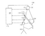
図1は、本発明の第1の実施例(実施例1)である切断面可視化装置100の構成概略図を示す図である。図1に示すように、切断面可視化装置100は、記憶手段および生成手段に対応する計算機110と、指定手段および指定具に対応する切断面指定具120と、表示手段に対応するプロジェクタ130と、視点検出手段に対応する視点検出センサ140と、被指定物検出手段に対応する被指定物検出センサ150とを備えている。切断面指定具120、プロジェクタ130、視点検出センサ140および被指定物検出センサ150はそれぞれ計算機110と電気的に接続されている。
Hereinafter, an example (example) of a preferred embodiment of the present invention will be described with reference to the accompanying drawings. Of course, the following examples do not limit the technical scope of the present invention.
Example 1
FIG. 1 is a diagram showing a schematic configuration of a cut
計算機110は、図示しないが演算部や記憶部等の通常パーソナルコンピュータが備えている機能を備えており、対象物のボリュームデータを記憶するとともに、切断面指定具120による対象物の切断面Aの指定に基づいて、ボリュームデータを加工し、その加工した切断面Aの画像データ(以下、切断面画像データという。)を表示するものである。ボリュームデータは、ボクセルデータで構成されており、本実施例においては、対象物として人体を用いておりボリュームデータが人体内の臓器・骨データにより構成されている例を示す。なお、本実施例では対象物(人体)に対して直接切断面Aを指定するのではなく、対象物と近似する形態を有する被指定物としての人体模型500を対象物のいわば代用として用いることにより対象物の切断面Aを指定している。
Although not shown, the
計算機110は、このボクセルデータより、切断面画像データを生成するのである。換言すれば、ボリュームデータから切断面Aに応じたピクセルデータを生成するのである。また、計算機110は、人体模型500の表面形状に関するデータ(表面形状データ)を記憶しており、この表面形状データに基づいて、切断面画像データを補正するように構成されている。
The
切断面指定具120は、対象物の切断面Aを人体模型500に対して指定するものであり、略コ字状に構成された保持部材121と、該保持部材121に取着され、切断面指定具120の位置および姿勢を検出するための切断面検出センサ122とによって構成されている。なお、この切断面検出センサ122が少なくとも1つの位置姿勢センサに対応する。保持部材121が略コ字状に構成されているので、保持部材121によって特定される面、すなわち人体模型500にて代用している対象物の切断面Aを観察者600に対し視覚を通して直感的に把握させることができるのである。したがって、切断面指定具120では、立体形状を有する対象物に対して任意の切断面を一度の操作で指定することができる。
The cutting
また、位置姿勢センサに対応する切断面検出センサ122によって切断面指定具120の位置および姿勢が検出されるので、同検出結果に基づいて、計算機110が切断面指定具120と人体模型500との相対位置および相対姿勢を計算することが可能となる。
In addition, since the position and orientation of the cutting
図2aおよび図2bは、切断面指定具120を用いて人体模型500に対し対象物の切断面Aを指定した場合の画像の表示について示す図である。切断面指定具120により図2aに示すような形で人体模型500に対する指定を行うと、計算機110によりその指定に対応して切断面Aの切断面画像データが表示されるのである。図2aでは切断面A以外の切断面も図示しているが、切断面指定具120を用いて人体模型500に対する適宜箇所の指定の度合いに応じて切断面画像データの表示の度合いが変更する。
FIGS. 2A and 2B are diagrams illustrating image display when the cutting plane A of the object is specified for the
また、図2bに示すように、人体模型500の一部(同図では胸部前側)に切断面指定具120によって指定される切断面が掛かるように位置させることにより、対象物における該一部のみの切断面画像データを人体模型500に表示させることも可能である。なお、この場合には、切断面指定具120を図面中下向きに連続的に移動或いは回転等させた場合でも、切断面検出センサ122が切断面指定具120の位置および姿勢の変化を検出し、位置或いは姿勢変化後における対象物の切断面の切断面画像データを人体模型500に表示することができる。
Further, as shown in FIG. 2b, by positioning the
このように観察者600が人体模型500に対して対象物の切断面Aを指定するにあたり、切断面指定具120を人体模型500に直接あてがうことにより人体模型500を通して対象物の切断面Aを指定することが可能となる。このため、例えば、マウス等を用いて指定する従来技術のように、何らかの約束毎に基づいた逐次の操作をしなくてもよいし、操作方法を覚えたり、操作回数が多くなるなどの煩雑さを解消することが可能となる。更には、画面を見ながらの操作しなくても良いため、観察者600に対して切断面Aを直感的に把握させやすくすることが可能となる。
Thus, when the
プロジェクタ130は、計算機110で計算されたピクセルデータを人体模型500の表面に投影することにより表示するものである。なお、人体模型500はプロジェクタ130の被投影物(スクリーン)としての機能も備えているので、表面には画像表示の妨げとなる模様などが存在しないものが好ましい。
The
このように人体模型500の表面に切断面画像データを表示することにより、観察者600は視覚的に人体模型500上で対象物の切断面画像を視認することができ、本実施例の切断面可視化装置100はあたかも対象物そのものを切断したかのような視覚的影響(画像)を観察者600に与えることができるのである。ここで、プロジェクタ130により表示される投影画像は、切断面画像データよりも大きくとられている。これにより、人体模型500を動かした場合にも、その人体模型500に対して切断面画像データを表示することが可能となるのである。換言すれば、人体模型500が固定されている場合(人体模型500が動かない場合)には、切断面画像データと投影画像とがほぼ同一の大きさであっても、支障は少ないと思われる。
Thus, by displaying the cut surface image data on the surface of the
また、プロジェクタ130には、このプロジェクタ130の位置及び姿勢を検出する手段(プロジェクタ検出手段)であるプロジェクタ検出センサ131が設けられている。このプロジェクタ検出センサ131の検出データ(出力信号)は、計算機110により、ボリュームデータから切断面画像データの生成に使用される。これにより、プロジェクタ130と人体模型500との相対位置および相対姿勢が分かるため、適切な画像データを人体模型500に投影することが可能となる。
Further, the
視点検出センサ140は、観察者600の視点を検出するものであり、観察者600自身が保持可能とされている(図示しないが眼鏡等に設けられると良い)。この視点検出センサ140の検出データ(視点)は計算機110に送信され、計算機110により、視点検出センサ140の検出結果に基づいて、ボリュームデータから切断面画像データの生成に使用される。ここで、前述の通り、プロジェクタ130による切断面画像データの表示は、人体模型500の表面への投影によって行われる。このため、視点検出センサ140の検出データに基づいて、画像データを生成することにより、観察者600の視点位置に基づいた画像を生成しかつ人体模型500上に投影することができるのである。
The
被指定物検出センサ150は、人体模型500の位置および姿勢を検出するものであり、この被指定物検出センサ150の検出データは、計算機110に送信される。この検出データは、計算機110により、切断面画像データの生成に使用される。この被指定物検出センサ150を設けない場合には、人体模型500が固定されないと適切な表示や切断面Aの指定を行うことができないが、被指定物検出センサ150を設けることによって、人体模型500を動かした場合にも、適切な表示や切断面Aの指定を行うことが可能となる。これにより、例えば、人体を表面(上面)側から見た切断面Aの他、人体模型500を裏返すことにより人体を裏面(下面)から見た切断面Aの投影が可能となるのである。
(作用)
次に、図3を参照して、上記のように構成された切断面可視化装置100における各センサ信号等のデータの流れについて説明する。図3に示すように、切断面可視化装置100においては、対象物である人体のボリュームデータに加え、人体模型500の表面形状データ(形状データ)、及びプロジェクタ検出センサ131の検出データが事前に記憶されている。これらは、いずれも定数であるからである。ここで、切断面指定具120により人体模型500に対して対象物の切断面Aが指定されると、切断面検出センサ122の検出データ(変数)、被指定物検出センサ150の検出データ(変数)および視点検出センサ140の検出データ(変数)に基づいて、ボリュームデータを加工して、切断面画像データを生成する。更に、視点検出センサ140の検出データ(変数)、被指定物検出センサ150の検出データ(変数)、及び、プロジェクタ検出センサ131の検出データに基づいて、切断面画像データを補正し、この補正された画像をプロジェクタ130から人体模型500の表面に投影して切断面を表示する。
The designated
(Function)
Next, with reference to FIG. 3, the flow of data such as each sensor signal in the cut
次に、図4を参照して、切断面可視化装置100の作用についてより詳細に説明すべく、かかる切断面可視化装置100において実行される処理について説明する。まず、事前記憶処理を実行する(S1)。このS1の処理においては、対象物のボリュームデータ等の事前に記憶すべきデータを記憶する。これらは変数でないので、一度記憶してしまえば、S1の処理を実行するに及ばない。
Next, processing executed in the cut
次に、第1段階切断面画像データ生成処理を実行する(S2)。S2の処理においては、被指定物検出センサ150の検出データおよび切断面検出センサ122の検出データに基づいて、計算機110により人体模型500と切断面指定具120との間の相対位置及び相対姿勢を算出し、その算出結果に基づいて対象物における切断位置を算出することによって第1段階の切断面画像データを生成する。ここで、算出に当たっては、視点検出センサ140の検出データより切断面指定具120のいずれより観察者600が切断面をみているかも考慮される。
Next, a first stage cut surface image data generation process is executed (S2). In the process of S <b> 2, based on the detection data of the specified
次に、第2段階切断面画像データ生成処理を実行する(S3)。このS3の処理においては、視点検出センサ140の検出データに基づいて、第1段階の切断面画像データを補正(変形)し、第2段階の切断面画像データを生成する。
Next, a second stage cut surface image data generation process is executed (S3). In the process of S3, the first-stage cut surface image data is corrected (deformed) based on the detection data of the
次に、第3段階切断面画像データ生成処理を実行する(S4)。このS4の処理においては、被指定物検出センサ150の検出データおよびプロジェクタ検出センサ131の検出データに基づいて、人体模型500とプロジェクタ130との相対位置を算出し、この算出結果に基づいて、第3段階の切断面画像データを補正(回転、並行移動等)させ、第3段階の切断面画像データを生成する。
Next, a third stage cut surface image data generation process is executed (S4). In the process of S4, the relative position between the
次に、第4段階切断面画像データ生成処理を実行する(S5)。このS5の処理においては、事前に入力された人体模型500の表面形状データに基づいて、第3段階の切断面画像データを補正(変形)し、第4段階の切断面画像データを生成する。これにより、人体模型500に投影した場合における切断面画像の歪みを補正することができる。
Next, a fourth stage cut surface image data generation process is executed (S5). In the process of S5, the third-stage cut surface image data is corrected (deformed) based on the surface shape data of the
次に、表示処理を実行する(S6)。このS6の処理においては、第4段階の切断面画像データをプロジェクタ130より人体模型500の表面に投影して表示するのである。これにより、対象物である人体をあたかも切断したかのような切断画像が人体模型500上に表れることとなる。
Next, display processing is executed (S6). In the process of S6, the cut surface image data in the fourth stage is projected from the
なお、切断面画像データの生成順序は、何ら限定されるものではない。例えば、S3の処理、S4の処理及びS5の処理は、相互に入れ替えてもよいし、S4の処理とS5の処理は同時に行っても良い。
(実施例2)
以下、図5乃至図7を参照して、本発明の第2の実施例(実施例2)について説明する。実施例2の切断面可視化装置200を説明するに当たっては、実施例1と異なる点に重点をおいて説明し、同一の部分の説明については、省略する。
Note that the generation order of the cut surface image data is not limited at all. For example, the processing of S3, the processing of S4, and the processing of S5 may be interchanged, or the processing of S4 and the processing of S5 may be performed simultaneously.
(Example 2)
Hereinafter, a second embodiment (embodiment 2) of the present invention will be described with reference to FIGS. In describing the cut
実施例2の切断面可視化装置200は、実施例1の切断面可視化装置が人体模型500に切断面画像データを表示するのに対して、モニタ210に切断面画像データを表示する点において異なる。
The cut
切断面可視化装置200は、計算機110と、切断面指定具120と、被指定物検出センサ150と、モニタ(表示手段に対応する)210とを備えている。計算機110は、対象物のボリュームデータを記憶しており、切断面指定具120の切断面検出センサ122と人体模型500の被指定物検出センサ150とにより、切断面指定具120と人体模型500との相対位置および相対姿勢に基づいて、モニタ210に表示する切断面画像データを生成するように構成されているものである。この場合における視点は、モニタ210に対して所定の角度および距離となる位置に規定されている。
The cut
図6は、切断面可視化装置200における各センサ信号等のデータ(情報)の流れを示す図であるが、この図6に示すように、切断面可視化装置200においては、平面であるモニタ210で表示するために、実施例1と比較して、人体模型500の表面形状データおよびプロジェクタの位置データが不必要となる。当然、画像の補正も行う必要はない。
FIG. 6 is a diagram showing a flow of data (information) such as each sensor signal in the cut
図7は、実施例2の切断面可視化装置において実行される処理を示す図であるが、この図7に示すように、切断面可視化装置200においては、実施例1におけるS3乃至S5の処理を実行する必要はなく、S1、S2、及びS6の処理が実行される。なお、S1の処理においては、プロジェクタ130の位置データや人体模型500の表面形状データを記憶する必要はないし、S6の処理においては、プロジェクタ130からの投影に代えて、モニタ210に表示する処理が実行される。
FIG. 7 is a diagram illustrating processing executed in the cut surface visualization apparatus according to the second embodiment. As illustrated in FIG. 7, the cut
以上、実施例に基づき、本発明を説明したが、上記実施例は、本発明の趣旨を逸脱しない範囲内で種々の改良変形が可能であることはいうまでもなく、本発明の技術的範囲には、これらの改良変形も含まれる。 The present invention has been described based on the embodiments. However, it goes without saying that the above embodiments can be variously improved and modified without departing from the spirit of the present invention. Includes these improved variants.
例えば、上記実施例によれば、被指定物検出センサ150を備えており、人体模型500と切断面指定具120との相対位置および相対姿勢に基づいて対象物の切断面Aを指定したり、プロジェクタ130より人体模型500に投影される画像データを生成(変形)している。しかしながら、人体模型500が固定されている場合には、必ずしも、被指定物検出センサ150を設けなくても良い。
For example, according to the above embodiment, the specified
また、実施例1および実施例2によれば、計算機110がボリュームデータとしてボクセルデータを記憶していたが、必ずしも、ボクセルデータに限られるものではなく、MRIやCT等の撮影画像をボリュームデータとして記憶するように構成されても良い。また、ボリュームデータは、内部構造データ(基本骨格データ)を構成するボクセルデータに加え、血流や内蔵の動き等のアニメーションデータにより構成されても良い。
Further, according to the first and second embodiments, the
更に、実施例1および実施例2においては、被指定物が手及び頭のない上半身の人体模型500により構成され、ボリュームデータが人体の切断面(臓器および血管等)のデータにより構成されていたが、必ずしも、これに限定されるものではない。例えば、全身の人型の模型であってもよい他、生身の人間であってもよい。また、対象物そのものに対して切断面指定具120を用いてその切断面を指定してもよい。この場合には対象物及び被指定物がそれぞれ他方の機能をも兼用するこことなる。
Further, in the first and second embodiments, the specified object is composed of the
更には、自動車用ガソリンエンジン等の工業製品であってもよい。この場合には、ボリュームデータが工業製品の内部構造データ(例えば、自動車エンジンにおけるピストンやバルブの駆動)に加え、エンジン外部から内部に供給される燃料の流れ、エンジン内への吸気やエンジン外への排気の流れ、更にはエンジン外周部分における気流或いは熱分布等のアニメーションデータにより構成されてもよい。このように本発明では、対象物の内部のみならず外部をも含めて対象物の断面という表現を用いている。 Furthermore, it may be an industrial product such as an automobile gasoline engine. In this case, the volume data is in addition to the internal structure data of industrial products (for example, driving of pistons and valves in an automobile engine), the flow of fuel supplied from the outside of the engine, the intake into the engine, and the outside of the engine Further, it may be constituted by animation data such as an air flow or heat distribution in the outer periphery of the engine. Thus, in the present invention, the expression of a cross section of an object including not only the inside of the object but also the outside is used.
更に、実施例1および実施例2においては、保持部材121が略コ字状に構成されているが、保持部材121の形状は何ら略コ字状に限定されるものではなく、略U字状、略L字状等種々の形状とすることが可能である。
Furthermore, in Example 1 and Example 2, the holding
更に、実施例1においては、プロジェクタ130が固定されていたが、プロジェクタ130が回転および移動するように構成しても良い。この場合、人体模型500を固定するようにしても良い。
Further, in the first embodiment, the
本発明は、医療教育用装置や患者への説明用装置等の医療分野に応用できる他、エンジンの内部構造の説明用装置等の工業分野にも応用可能である。 The present invention can be applied not only to the medical field such as a medical education apparatus and a patient explanation apparatus, but also to an industrial field such as an explanation apparatus for an internal structure of an engine.
100,200…切断面可視化装置、110…記憶手段および生成手段としての計算機、120…指定手段としての切断面指定具、121…保持部材、122…切断面検出センサ、130…表示手段としてのプロジェクタ、131…プロジェクタ検出センサ、140…視点検出センサ、150…被指定物検出センサ、210…表示手段としてのモニター、500…被指定物としての人体模型、600…観察者。 DESCRIPTION OF SYMBOLS 100,200 ... Cutting surface visualization apparatus, 110 ... Computer as a memory | storage means and a production | generation means, 120 ... Cutting surface designation tool as a designation | designated means, 121 ... Holding member, 122 ... Cutting surface detection sensor, 130 ... Projector as a display means 131 ... Projector detection sensor, 140 ... Viewpoint detection sensor, 150 ... Designated object detection sensor, 210 ... Monitor as display means, 500 ... Human body model as designated object, 600 ... Observer.
Claims (5)
前記対象物のボリュームデータ及び被指定物の表面形状データを記憶する記憶手段と、
前記対象物の切断面を被指定物に対して指定する指定手段と、
該指定手段による切断面の指定に基づいて、前記記憶手段に記憶されているボリュームデータより前記対象物の切断面の画像データを生成する生成手段と、
該生成手段により生成された切断面の画像データを表示する表示手段と、
観察者の視点を検出する視点検出手段とを備え、
前記指定手段は、前記被指定物との相対位置および相対姿勢により対象物の切断面を指定する指定具を備え、
前記生成手段は、前記視点検出手段により検出された視点に基づいて画像データに観察者の視点位置に応じた変形をするとともに、前記被指定物の表面形状データに基づいて画像データを変形し被指定物に投影した場合における切断面の画像の歪みを補正するものであり、
前記表示手段は、前記指定具により被指定物に対して指定された切断面の位置に画像データを投影することにより表示するものであることを特徴とする切断面可視化装置。 A cutting surface visualization device capable of displaying an image of an arbitrary cutting surface of an object,
Storage means for storing volume data of the object and surface shape data of the specified object;
Designating means for designating the cut surface of the object with respect to the designated object;
Generating means for generating image data of the cut surface of the object from the volume data stored in the storage means based on the designation of the cut surface by the specifying means;
Display means for displaying the image data of the cut surface generated by the generating means;
A viewpoint detection means for detecting an observer's viewpoint,
The designation means includes a designation tool for designating a cutting surface of an object by a relative position and a relative attitude with respect to the designated object,
The generation unit is configured to a deformation corresponding to the observer's viewpoint position to the image data based on the viewpoint detected by the viewpoint detection means, the deformed image data on the basis of the surface shape data of the object specified object It corrects the distortion of the image of the cut surface when projected onto the specified object.
The cutting surface visualization device, wherein the display means displays the image data by projecting it onto the position of the cutting surface specified for the specified object by the specifying tool.
生成手段は、前記記憶手段に記憶されたボクセルデータから画像データを生成するものであることを特徴とする請求項1または2に記載の切断面可視化装置。 The storage means stores volume data composed of voxel data,
The cutting surface visualization device according to claim 1 or 2, wherein the generation unit generates image data from voxel data stored in the storage unit.
生成手段は、前記被指定物検出手段により検出された位置及び姿勢に基づいて、画像データを回転或いは平行移動して前記被指定物の位置及び姿勢に応じた補正をするものであることを特徴とする請求項1から4の何れかに記載の切断面可視化装置。 A designated object detection means for detecting the position and orientation of the designated object;
The generation unit is configured to perform correction according to the position and orientation of the designated object by rotating or translating the image data based on the position and orientation detected by the designated object detecting unit. The cut surface visualization apparatus according to any one of claims 1 to 4.
Priority Applications (1)
| Application Number | Priority Date | Filing Date | Title |
|---|---|---|---|
| JP2006089777A JP4792578B2 (en) | 2006-03-29 | 2006-03-29 | Cut surface visualization device |
Applications Claiming Priority (1)
| Application Number | Priority Date | Filing Date | Title |
|---|---|---|---|
| JP2006089777A JP4792578B2 (en) | 2006-03-29 | 2006-03-29 | Cut surface visualization device |
Publications (2)
| Publication Number | Publication Date |
|---|---|
| JP2007265061A JP2007265061A (en) | 2007-10-11 |
| JP4792578B2 true JP4792578B2 (en) | 2011-10-12 |
Family
ID=38637979
Family Applications (1)
| Application Number | Title | Priority Date | Filing Date |
|---|---|---|---|
| JP2006089777A Active JP4792578B2 (en) | 2006-03-29 | 2006-03-29 | Cut surface visualization device |
Country Status (1)
| Country | Link |
|---|---|
| JP (1) | JP4792578B2 (en) |
Cited By (1)
| Publication number | Priority date | Publication date | Assignee | Title |
|---|---|---|---|---|
| CN104173073A (en) * | 2013-11-19 | 2014-12-03 | 上海联影医疗科技有限公司 | Three-dimensional positioning method |
Families Citing this family (1)
| Publication number | Priority date | Publication date | Assignee | Title |
|---|---|---|---|---|
| JP5024766B2 (en) * | 2008-03-11 | 2012-09-12 | 国立大学法人岐阜大学 | 3D display device |
Family Cites Families (3)
| Publication number | Priority date | Publication date | Assignee | Title |
|---|---|---|---|---|
| JP2000102036A (en) * | 1998-09-22 | 2000-04-07 | Mr System Kenkyusho:Kk | Composite actual feeling presentation system, composite actual feeling presentation method, man-machine interface device and man-machine interface method |
| JP4011340B2 (en) * | 2001-12-25 | 2007-11-21 | 株式会社日立メディコ | Surgery support system |
| JP4032293B2 (en) * | 2002-05-15 | 2008-01-16 | 株式会社日立メディコ | Ultrasound-magnetic resonance combined medical device |
-
2006
- 2006-03-29 JP JP2006089777A patent/JP4792578B2/en active Active
Cited By (1)
| Publication number | Priority date | Publication date | Assignee | Title |
|---|---|---|---|---|
| CN104173073A (en) * | 2013-11-19 | 2014-12-03 | 上海联影医疗科技有限公司 | Three-dimensional positioning method |
Also Published As
| Publication number | Publication date |
|---|---|
| JP2007265061A (en) | 2007-10-11 |
Similar Documents
| Publication | Publication Date | Title |
|---|---|---|
| JP3769316B2 (en) | Real-time three-dimensional indicating device and method for assisting operator in confirming three-dimensional position in subject | |
| Pai et al. | Augmented reality–based programming, planning and simulation of a robotic work cell | |
| US20170042631A1 (en) | Intra-operative medical image viewing system and method | |
| WO2022073290A1 (en) | Surgical robot, and graphical control device and graphic display method therefor | |
| US20160328887A1 (en) | Systems and methods for providing assistance for manipulating objects using virtual proxies and virtual replicas | |
| CN113194862A (en) | Setting up a surgical robot using an enhanced mirror display | |
| WO2012173141A1 (en) | Image processing apparatus, image processing method, and program | |
| JP6318542B2 (en) | Display control method, display control program, and information processing apparatus | |
| JP2011521318A (en) | Interactive virtual reality image generation system | |
| JP2014229057A (en) | Component assembly work support system and component assembly method | |
| JP5815513B2 (en) | Image processing apparatus and image processing method | |
| JP6576042B2 (en) | Display control apparatus and method, and program | |
| CA2796514A1 (en) | Method and device for representing synthetic environments | |
| US20150339859A1 (en) | Apparatus and method for navigating through volume image | |
| WO2021202609A1 (en) | Method and system for facilitating remote presentation or interaction | |
| CN111991084B (en) | Surgical robot, virtual imaging control method thereof and virtual imaging control device thereof | |
| JP2007272889A (en) | Image processing device | |
| EP2509013A1 (en) | 3D image navigation method | |
| JP2008085641A (en) | Three-dimensional image display | |
| JP4792578B2 (en) | Cut surface visualization device | |
| JP6112689B1 (en) | Superimposed image display system | |
| JPH06131442A (en) | Three-dimensional virtual image modeling device | |
| US9786090B2 (en) | System for colocating a touch screen and a virtual object, and device for manipulating virtual objects implementing such a system | |
| JP2005107972A (en) | Mixed reality presentation method and mixed reality presentation system | |
| US10854005B2 (en) | Visualization of ultrasound images in physical space |
Legal Events
| Date | Code | Title | Description |
|---|---|---|---|
| A521 | Written amendment |
Free format text: JAPANESE INTERMEDIATE CODE: A523 Effective date: 20080207 |
|
| A621 | Written request for application examination |
Free format text: JAPANESE INTERMEDIATE CODE: A621 Effective date: 20090121 |
|
| A131 | Notification of reasons for refusal |
Free format text: JAPANESE INTERMEDIATE CODE: A131 Effective date: 20110118 |
|
| A521 | Written amendment |
Free format text: JAPANESE INTERMEDIATE CODE: A523 Effective date: 20110318 |
|
| A131 | Notification of reasons for refusal |
Free format text: JAPANESE INTERMEDIATE CODE: A131 Effective date: 20110412 |
|
| A521 | Written amendment |
Free format text: JAPANESE INTERMEDIATE CODE: A523 Effective date: 20110610 |
|
| TRDD | Decision of grant or rejection written | ||
| A01 | Written decision to grant a patent or to grant a registration (utility model) |
Free format text: JAPANESE INTERMEDIATE CODE: A01 Effective date: 20110628 |
|
| A01 | Written decision to grant a patent or to grant a registration (utility model) |
Free format text: JAPANESE INTERMEDIATE CODE: A01 |
|
| R150 | Certificate of patent or registration of utility model |
Ref document number: 4792578 Country of ref document: JP Free format text: JAPANESE INTERMEDIATE CODE: R150 Free format text: JAPANESE INTERMEDIATE CODE: R150 |
|
| S111 | Request for change of ownership or part of ownership |
Free format text: JAPANESE INTERMEDIATE CODE: R313111 |
|
| R350 | Written notification of registration of transfer |
Free format text: JAPANESE INTERMEDIATE CODE: R350 |