JP4046833B2 - Concrete mixer - Google Patents
Concrete mixer Download PDFInfo
- Publication number
- JP4046833B2 JP4046833B2 JP04437398A JP4437398A JP4046833B2 JP 4046833 B2 JP4046833 B2 JP 4046833B2 JP 04437398 A JP04437398 A JP 04437398A JP 4437398 A JP4437398 A JP 4437398A JP 4046833 B2 JP4046833 B2 JP 4046833B2
- Authority
- JP
- Japan
- Prior art keywords
- mixing
- shaft
- arm
- cylindrical
- blade
- Prior art date
- Legal status (The legal status is an assumption and is not a legal conclusion. Google has not performed a legal analysis and makes no representation as to the accuracy of the status listed.)
- Expired - Fee Related
Links
Images

Landscapes
- Preparation Of Clay, And Manufacture Of Mixtures Containing Clay Or Cement (AREA)
- Mixers Of The Rotary Stirring Type (AREA)
Description
【0001】
【発明の属する技術分野】
本発明は、コンクリートミキサに関し、特に、高流動コンクリートの製造に適したものに関する。
【0002】
【従来の技術】
従来のコンクリートミキサとしては、例えば、特公平3−68805号公報に示すものがある。すなわち、底部に円筒内面を有する混合槽と、混合槽に円筒内面の円筒中心線上で設けられ、動力により回転可能なシャフトと、シャフトに固定され、混合槽の底部側に位置するとき、エッジが混合槽の一端側から中間部にかけて円筒内面に沿って螺旋状に伸びる第1混合羽根と、シャフトに固定され、混合槽の底部側に位置するとき、エッジが混合槽の他端側から中間部にかけて円筒内面に沿って第1混合羽根と反対回りに螺旋状に伸びる第2混合羽根と、シャフトの中間部に固定され、第1混合羽根と第2混合羽根とを連結する混合アームとを有し、混合槽の中にコンクリート材料を入れ、シャフトを回転させて、第1混合羽根と第2混合羽根とでコンクリート材料を混練りするようになっている。
【0003】
【発明が解決しようとする課題】
しかしながら、従来のコンクリートミキサでは、高流動コンクリートを製造するためその材料を混練りするとき、高流動コンクリートとして最適な状態まで混練りするのに一般のコンクリートを混練りするときの数倍もの時間がかかるという問題点があった。
【0004】
本発明は、このような従来の問題点に着目してなされたもので、短時間で高流動コンクリートを製造することができるコンクリートミキサを提供することを目的としている。
【0005】
【課題を解決するための手段】
上記目的を達成するために、本発明に係るコンクリートミキサは、底部に円筒内面を有する混合槽と、前記混合槽に前記円筒内面の円筒中心線上で設けられ、動力により回転可能なシャフトと、前記シャフトに固定され、前記混合槽の底部側に位置するとき、エッジが前記混合槽の一端側から中間部にかけて前記円筒内面に沿って螺旋状に伸びる第1混合羽根と、前記シャフトに固定され、前記混合槽の底部側に位置するとき、エッジが前記混合槽の他端側から中間部にかけて前記円筒内面に沿って前記第1混合羽根と反対回りに螺旋状に伸びる第2混合羽根と、前記シャフトの中間部に固定され、前記第1混合羽根と前記第2混合羽根とを連結する混合アームとを有するコンクリートミキサにおいて:アーム部と半円筒部とを有し、前記アーム部は前記シャフトの中間部に固定されて前記シャフトおよび前記混合アームに垂直に伸び、前記半円筒部は前記アーム部の両端に設けられ、前記半円筒部の円筒中心線は前記アーム部の上にあって前記円筒内面の円筒中心線と平行に伸びる第1補助混合具を有することを、特徴とする。
【0006】
本発明に係るコンクリートミキサでは、コンクリートを製造するとき、混合槽の中にコンクリート材料を入れ、シャフトを回転させて、第1混合羽根と第2混合羽根とでコンクリート材料を混練りする。このとき、シャフトの回転とともに、第1補助混合具が、アーム部の両端の半円筒部により混合槽の底部の円筒内面との間でコンクリート材料を押しつぶすようにしながら回転する。これにより、高流動コンクリート材料を混練りするとき、特に粉体の材料が充分に練られ、短時間で高流動コンクリートを練り上げることができる。本発明に係るコンクリートミキサは、高流動コンクリートに限らず、一般のコンクリートの製造に用いることができる。
【0007】
本発明に係るコンクリートミキサは、請求項1のコンクリートミキサにおいて、前記混合アームを貫通して前記混合アームの長さ方向にそれぞれ間隔をあけて前記混合アームに固定され、前記円筒内面の円筒中心線とそれぞれ平行に伸びる複数の第2補助混合具を有することを、特徴とする。
【0008】
本発明に係るコンクリートミキサでは、シャフトの回転とともに、第2補助混合具が第1混合羽根と第2混合羽根との間で回転し、第1混合羽根と第2混合羽根との間の混練りされにくいコンクリート材料を混練りする。これにより、短時間で高流動コンクリートを練り上げる効果を高めることができる。
【0009】
【発明の実施の形態】
以下、図面に基づき本発明の実施の形態について説明する。
図1〜図3は、本発明の実施の形態を示している。
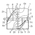
図1〜図3に示すように、コンクリートミキサ1は、混合槽2と、シャフト3と、第1混合羽根4と、第2混合羽根5と、3本の混合アーム6a,6b,6cと、第1補助混合具7と、第2補助混合具8とを有している。混合槽2は、底部に円筒内面2aを有し、コンクリート材料の投入口(図示せず)を上部に、排出口(図示せず)を下部に有している。シャフト3は、混合槽2の一端側2bおよび他端側2cの両端面を貫通して混合槽2に円筒内面2aの円筒中心線2d上で設けられ、混合槽2の外部でモータ(図示せず)により回転可能となっている。
【0010】
第1混合羽根4は、シャフト3に固定され、混合槽2の底部側に位置するとき、エッジ4aが混合槽2の一端側2bから中間部2eにかけて円筒内面2aに沿って螺旋状に伸びている。第2混合羽根5は、シャフト3に固定され、混合槽2の底部側に位置するとき、エッジ5aが混合槽2の他端側2cから中間部2eにかけて円筒内面2aに沿って第1混合羽根4と反対回りに螺旋状に伸びている。第1混合羽根4および第2混合羽根5には、表面に摩耗板9が張り付けられている。
【0011】
3本の混合アーム6a,6b,6cは、シャフト3の中央部とその両側にそれぞれ固定されている。中央部の混合アーム6aは、シャフト3を貫通させて、第1混合羽根4と第2混合羽根5とを連結している。両側の混合アーム6b,6cは、それぞれ第1混合羽根4、第2混合羽根5に接続されている。
【0012】
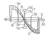
図2および図3に示すように、第1補助混合具7はアーム部7aと半円筒部7bとを有し、アーム部7aはシャフト3の中央部に固定されている。第1補助混合具7は、シャフト3を貫通してシャフト3および混合アーム6aに垂直に伸びている。半円筒部7bは、アーム部7aの両端に設けられている。図3に示すように、半円筒部7bの円筒中心線7cは、アーム部7aの上にあって円筒内面2aの円筒中心線2dと平行に伸びる。
【0013】
複数の第2補助混合具8は、それぞれ同じ長さの棒状部材から成る。各第2補助混合具8は、混合アーム6aを貫通して混合アーム6aの長さ方向にそれぞれ間隔をあけ、中央部で混合アーム6aに固定されている。各第2補助混合具8は、円筒内面2aの円筒中心線2dとそれぞれ平行に伸びている。
【0014】
次に、作用について説明する。
コンクリートミキサ1で高流動コンクリートを製造するとき、混合槽2の中に投入口から高流動コンクリート材料を入れる。高流動コンクリート材料は、セメント、水、砂、砂利、粉体および高性能減水剤から成る。高流動コンクリート材料の投入の配分および順番は、適宜、調製する。高流動コンクリート材料の投入後、モータでシャフト3を回転させて、第1混合羽根4と第2混合羽根5とで高流動コンクリート材料を混練りする。高流動コンクリート材料を混練りするとき、第1補助混合具7は、シャフト3および混合アーム6aに垂直に伸びているため、対向流の混合域の弱い部分を補う。
【0015】
シャフト3の回転とともに、第1補助混合具7は、アーム部7aの両端の半円筒部7bにより混合槽2の底部の円筒内面2aとの間で高流動コンクリート材料を押しつぶすようにしながら回転する。これにより、高流動コンクリート材料を混練りするとき、高性能減水剤の性能効果が発揮されて特に粉体の材料が充分に練られ、練り性能の向上によって通常の半分程度の短時間で高流動コンクリートを練り上げることができる。
【0016】
同時に、コンクリートミキサでは、シャフト3の回転とともに、複数の第2補助混合具8が第1混合羽根4と第2混合羽根5との間で回転し、第1混合羽根4と第2混合羽根5との間の混練りされにくい高流動コンクリート材料を混練りする。第2補助混合具8は、円筒内面2aの円筒中心線2dと平行に伸びて混合アーム6aに固定されているため、対向流の混合域の弱い部分を補い、効率よく混合する。これにより、短時間で高流動コンクリートを練り上げる効果を高めることができる。コンクリートミキサは、高流動コンクリートに限らず、他のタイプのコンクリートの製造にも用いることができる。
【0017】
なお、前述の実施の形態では、コンクリートミキサが一軸ミキサから成る場合について例示したが、コンクリートミキサとして二軸ミキサやパン型ミキサを採用可能なことはいうまでもない。
【0018】
【発明の効果】
本発明に係るコンクリートミキサによれば、第1補助混合具を有し、第1補助混合具はアーム部の両端に半円筒部を有するので、第1補助混合具が両端の半円筒部により混合槽の底部の円筒内面との間でコンクリート材料を押しつぶすようにしながら回転し、短時間で高流動コンクリートを練り上げることができる。
【0019】
特に、請求項2の本発明に係るコンクリートミキサによれば、第2補助混合具を有し、第2補助混合具は混合アームの長さ方向にそれぞれ間隔をあけて固定され、混合槽の底部の円筒内面の円筒中心線とそれぞれ平行に伸びるので、第1混合羽根と第2混合羽根との間の混練りされにくいコンクリート材料を混練りし、短時間で高流動コンクリートを練り上げる効果を高めることができる。
【0020】
【図面の簡単な説明】
【図1】本発明の実施の形態のコンクリートミキサの要部の正面図である。
【図2】図1のコンクリートミキサの混合槽を除いた要部の底面図である。
【図3】図1のコンクリートミキサの混合槽を除いた要部の側面図である。
【符号の説明】
1 コンクリートミキサ
2 混合槽
3 シャフト
4 第1混合羽根
5 第2混合羽根
6a,6b,6c 混合アーム
7 第1補助混合具
8 第2補助混合具[0001]
BACKGROUND OF THE INVENTION
The present invention relates to a concrete mixer, and more particularly to a concrete mixer that is suitable for producing high-fluidity concrete.
[0002]
[Prior art]
An example of a conventional concrete mixer is disclosed in Japanese Patent Publication No. 3-68805. That is, a mixing tank having a cylindrical inner surface at the bottom, a shaft provided on the cylindrical center line of the cylindrical inner surface of the mixing tank, rotatable by power, fixed to the shaft, and positioned on the bottom side of the mixing tank, the edge is A first mixing blade extending in a spiral shape along the inner surface of the cylinder from one end side to the middle part of the mixing tank and a shaft fixed to the bottom side of the mixing tank when the edge is positioned from the other end side of the mixing tank to the intermediate part And a second mixing blade that spirally extends in the opposite direction to the first mixing blade along the inner surface of the cylinder, and a mixing arm that is fixed to an intermediate portion of the shaft and connects the first mixing blade and the second mixing blade. Then, the concrete material is put into the mixing tank, the shaft is rotated, and the concrete material is kneaded by the first mixing blade and the second mixing blade.
[0003]
[Problems to be solved by the invention]
However, in the conventional concrete mixer, when kneading the material to produce high-fluidity concrete, it takes several times as long as kneading ordinary concrete to knead to the optimum state as high-fluidity concrete. There was a problem that it took.
[0004]
The present invention has been made paying attention to such a conventional problem, and an object thereof is to provide a concrete mixer capable of producing high-fluidity concrete in a short time.
[0005]
[Means for Solving the Problems]
In order to achieve the above object, a concrete mixer according to the present invention includes a mixing tank having a cylindrical inner surface at the bottom, a shaft provided on the cylindrical center line of the cylindrical inner surface of the mixing tank and rotatable by power, When fixed to the shaft and positioned on the bottom side of the mixing tank, the edge is fixed to the shaft, and a first mixing blade extending spirally along the inner surface of the cylinder from one end side to the intermediate part of the mixing tank, When located on the bottom side of the mixing tank, the second mixing blade spirally extending in the opposite direction to the first mixing blade along the cylindrical inner surface from the other end side of the mixing tank to the intermediate portion; In a concrete mixer having a mixing arm fixed to an intermediate portion of a shaft and connecting the first mixing blade and the second mixing blade: an arm portion and a semi-cylindrical portion, The middle part is fixed to the middle part of the shaft and extends perpendicularly to the shaft and the mixing arm, the semi-cylindrical part is provided at both ends of the arm part, and the cylindrical center line of the semi-cylindrical part is It has the 1st auxiliary | assistant mixing tool which is on and extends in parallel with the cylinder centerline of the said cylinder inner surface.
[0006]
In the concrete mixer according to the present invention, when producing concrete, the concrete material is put in the mixing tank, the shaft is rotated, and the concrete material is kneaded by the first mixing blade and the second mixing blade. At this time, with the rotation of the shaft, the first auxiliary mixing tool rotates while crushing the concrete material between the semi-cylindrical portions at both ends of the arm portion and the cylindrical inner surface at the bottom of the mixing tank. Thereby, when kneading | mixing a high fluidity concrete material, especially the material of a powder is fully kneaded and it can knead a high fluidity concrete in a short time. The concrete mixer which concerns on this invention can be used for manufacture of not only high fluid concrete but general concrete.
[0007]
A concrete mixer according to the present invention is the concrete mixer according to
[0008]
In the concrete mixer according to the present invention, as the shaft rotates, the second auxiliary mixing tool rotates between the first mixing blade and the second mixing blade, and kneading between the first mixing blade and the second mixing blade. Knead the hard-to-react concrete material. Thereby, the effect which kneads high fluidity concrete in a short time can be heightened.
[0009]
DETAILED DESCRIPTION OF THE INVENTION
Hereinafter, embodiments of the present invention will be described with reference to the drawings.
1 to 3 show an embodiment of the present invention.
As shown in FIGS. 1 to 3, the
[0010]
When the
[0011]
The three mixing
[0012]
As shown in FIGS. 2 and 3, the first
[0013]
The plurality of second
[0014]
Next, the operation will be described.
When producing high-fluidity concrete with the
[0015]
Along with the rotation of the
[0016]
At the same time, in the concrete mixer, as the
[0017]
In the above-described embodiment, the concrete mixer is composed of a single-shaft mixer. However, it goes without saying that a biaxial mixer or a pan-type mixer can be adopted as the concrete mixer.
[0018]
【The invention's effect】
According to the concrete mixer according to the present invention, the first auxiliary mixing tool has the semi-cylindrical parts at both ends of the arm portion, so the first auxiliary mixing tool is mixed by the semi-cylindrical parts at both ends. It rotates while crushing the concrete material between the cylindrical inner surface at the bottom of the tank, and high-fluidity concrete can be kneaded in a short time.
[0019]
In particular, the concrete mixer according to the present invention of claim 2 has the second auxiliary mixing tool, and the second auxiliary mixing tool is fixed at intervals in the length direction of the mixing arm, and the bottom of the mixing tank. Since it extends parallel to the cylinder center line of the inner surface of the cylinder, it is possible to knead the concrete material that is difficult to knead between the first mixing blade and the second mixing blade and enhance the effect of kneading the high-fluidity concrete in a short time. Can do.
[0020]
[Brief description of the drawings]
FIG. 1 is a front view of a main part of a concrete mixer according to an embodiment of the present invention.
FIG. 2 is a bottom view of the main part of the concrete mixer of FIG. 1 excluding the mixing tank.
FIG. 3 is a side view of the main part of the concrete mixer of FIG. 1 excluding the mixing tank.
[Explanation of symbols]
DESCRIPTION OF
Claims (2)
アーム部と半円筒部とを有し、前記アーム部は前記シャフトの中間部に固定されて前記シャフトおよび前記混合アームに垂直に伸び、前記半円筒部は前記アーム部の両端に設けられ、前記半円筒部の円筒中心線は前記アーム部の上にあって前記円筒内面の円筒中心線と平行に伸びる第1補助混合具を有することを、
特徴とするコンクリートミキサ。When the mixing tank having a cylindrical inner surface at the bottom, the shaft provided on the cylindrical inner line of the cylindrical inner surface of the mixing tank, rotatable by power, and fixed to the shaft, when located on the bottom side of the mixing tank, When the edge is fixed to the shaft and positioned on the bottom side of the mixing tank, the edge is located on the bottom side of the mixing tank. The first mixing blade extends spirally along the cylindrical inner surface from one end side to the middle of the mixing tank. A second mixing blade extending spirally in the opposite direction from the first mixing blade along the cylindrical inner surface from the other end side to the intermediate portion, and fixed to the intermediate portion of the shaft, and the first mixing blade and the first mixing blade In a concrete mixer having a mixing arm connecting two mixing blades,
An arm portion and a semi-cylindrical portion, the arm portion being fixed to an intermediate portion of the shaft and extending perpendicularly to the shaft and the mixing arm, the semi-cylindrical portions being provided at both ends of the arm portion, The cylindrical center line of the semi-cylindrical part has a first auxiliary mixing tool that extends above the arm part and extends parallel to the cylindrical center line of the cylindrical inner surface.
A featured concrete mixer.
Priority Applications (1)
| Application Number | Priority Date | Filing Date | Title |
|---|---|---|---|
| JP04437398A JP4046833B2 (en) | 1998-02-09 | 1998-02-09 | Concrete mixer |
Applications Claiming Priority (1)
| Application Number | Priority Date | Filing Date | Title |
|---|---|---|---|
| JP04437398A JP4046833B2 (en) | 1998-02-09 | 1998-02-09 | Concrete mixer |
Publications (2)
| Publication Number | Publication Date |
|---|---|
| JPH11221820A JPH11221820A (en) | 1999-08-17 |
| JP4046833B2 true JP4046833B2 (en) | 2008-02-13 |
Family
ID=12689713
Family Applications (1)
| Application Number | Title | Priority Date | Filing Date |
|---|---|---|---|
| JP04437398A Expired - Fee Related JP4046833B2 (en) | 1998-02-09 | 1998-02-09 | Concrete mixer |
Country Status (1)
| Country | Link |
|---|---|
| JP (1) | JP4046833B2 (en) |
Families Citing this family (4)
| Publication number | Priority date | Publication date | Assignee | Title |
|---|---|---|---|---|
| SK50152013A3 (en) * | 2013-05-06 | 2014-12-04 | Anton Hrdlička | Fermentation tank with mechanical cooling and / or degassing device |
| KR102040078B1 (en) * | 2017-12-19 | 2019-11-27 | 김명대 | Rotating drum for regeneration device of waste ascon |
| KR102355027B1 (en) * | 2020-10-20 | 2022-01-24 | 김용태 | Food Waste, Livestock Manure, Animal and Plant Residues, Sewage Sludge Decomposition Device |
| KR102355028B1 (en) * | 2020-10-20 | 2022-01-24 | 김용태 | Decomposition Device using Microorganisms for Food Waste, Livestock Manure, Animal and Plant Residues, Sewage Sludge and Method thereof |
-
1998
- 1998-02-09 JP JP04437398A patent/JP4046833B2/en not_active Expired - Fee Related
Also Published As
| Publication number | Publication date |
|---|---|
| JPH11221820A (en) | 1999-08-17 |
Similar Documents
| Publication | Publication Date | Title |
|---|---|---|
| KR960010200B1 (en) | Internal batch mixing machine | |
| JP2000317290A (en) | Mixing equipment | |
| US4478515A (en) | Mortar mixer with triple eight mixing action | |
| JP4046833B2 (en) | Concrete mixer | |
| CA2428700A1 (en) | Four wing, non-intermeshing rotors for synchronous drive to provide improved dispersive and distributive mixing in internal batch mixers | |
| JP2006346510A (en) | Twin screw mixer | |
| JP4059453B2 (en) | Biaxial concrete mixer | |
| JP3767724B2 (en) | Concrete mixing drum mixer | |
| JP4041572B2 (en) | Biaxial concrete mixer | |
| JP3432789B2 (en) | Rotary shaft cleaning ring for forced biaxial concrete mixer | |
| CN212021160U (en) | Compact ceramic pug mill | |
| CN211725595U (en) | Three-axis continuous mixing tank | |
| JPH10151334A (en) | Kneading rotor in kneading equipment | |
| JP2889758B2 (en) | Horizontal twin-screw kneader | |
| WO1998016305A1 (en) | Helical ribbon mixer | |
| CN209832167U (en) | A wear-resistant stirrer | |
| JP4424738B2 (en) | Kneading machine | |
| CN207972134U (en) | A kind of twin shaft concrete central mix plant | |
| CN218795229U (en) | Novel adhesive mixing machine for bonding neodymium iron boron magnetic powder | |
| JP2007106012A (en) | Mixing method of ready-mixed concrete using a twin screw mixer | |
| CN218249621U (en) | Horizontal double-shaft mixer | |
| CN221789107U (en) | Quick scraping device of vacuum homogenizing emulsifying machine | |
| JP4617248B2 (en) | 2-axis mixer | |
| CN223904218U (en) | Proportioning device for concrete processing | |
| CN222586188U (en) | Double-shaft mixer |
Legal Events
| Date | Code | Title | Description |
|---|---|---|---|
| A621 | Written request for application examination |
Free format text: JAPANESE INTERMEDIATE CODE: A621 Effective date: 20050201 |
|
| A977 | Report on retrieval |
Free format text: JAPANESE INTERMEDIATE CODE: A971007 Effective date: 20070612 |
|
| TRDD | Decision of grant or rejection written | ||
| A01 | Written decision to grant a patent or to grant a registration (utility model) |
Free format text: JAPANESE INTERMEDIATE CODE: A01 Effective date: 20071023 |
|
| A61 | First payment of annual fees (during grant procedure) |
Free format text: JAPANESE INTERMEDIATE CODE: A61 Effective date: 20071121 |
|
| FPAY | Renewal fee payment (event date is renewal date of database) |
Free format text: PAYMENT UNTIL: 20101130 Year of fee payment: 3 |
|
| R150 | Certificate of patent or registration of utility model |
Free format text: JAPANESE INTERMEDIATE CODE: R150 |
|
| FPAY | Renewal fee payment (event date is renewal date of database) |
Free format text: PAYMENT UNTIL: 20111130 Year of fee payment: 4 |
|
| FPAY | Renewal fee payment (event date is renewal date of database) |
Free format text: PAYMENT UNTIL: 20121130 Year of fee payment: 5 |
|
| FPAY | Renewal fee payment (event date is renewal date of database) |
Free format text: PAYMENT UNTIL: 20121130 Year of fee payment: 5 |
|
| FPAY | Renewal fee payment (event date is renewal date of database) |
Free format text: PAYMENT UNTIL: 20131130 Year of fee payment: 6 |
|
| R250 | Receipt of annual fees |
Free format text: JAPANESE INTERMEDIATE CODE: R250 |
|
| R250 | Receipt of annual fees |
Free format text: JAPANESE INTERMEDIATE CODE: R250 |
|
| R250 | Receipt of annual fees |
Free format text: JAPANESE INTERMEDIATE CODE: R250 |
|
| R250 | Receipt of annual fees |
Free format text: JAPANESE INTERMEDIATE CODE: R250 |
|
| LAPS | Cancellation because of no payment of annual fees |