JP4046832B2 - Engine control device - Google Patents
Engine control device Download PDFInfo
- Publication number
- JP4046832B2 JP4046832B2 JP03310798A JP3310798A JP4046832B2 JP 4046832 B2 JP4046832 B2 JP 4046832B2 JP 03310798 A JP03310798 A JP 03310798A JP 3310798 A JP3310798 A JP 3310798A JP 4046832 B2 JP4046832 B2 JP 4046832B2
- Authority
- JP
- Japan
- Prior art keywords
- value
- engine
- engine speed
- correction amount
- accelerator opening
- Prior art date
- Legal status (The legal status is an assumption and is not a legal conclusion. Google has not performed a legal analysis and makes no representation as to the accuracy of the status listed.)
- Expired - Fee Related
Links
- 239000000446 fuel Substances 0.000 claims description 40
- 230000004044 response Effects 0.000 claims description 2
- 238000000034 method Methods 0.000 description 29
- 230000008569 process Effects 0.000 description 29
- 230000008859 change Effects 0.000 description 19
- 238000010586 diagram Methods 0.000 description 12
- 238000002347 injection Methods 0.000 description 10
- 239000007924 injection Substances 0.000 description 10
- 230000000694 effects Effects 0.000 description 7
- 230000007812 deficiency Effects 0.000 description 3
- 238000010248 power generation Methods 0.000 description 3
- 230000002411 adverse Effects 0.000 description 2
- 238000002485 combustion reaction Methods 0.000 description 2
- 239000000498 cooling water Substances 0.000 description 2
- 230000002950 deficient Effects 0.000 description 2
- 238000005516 engineering process Methods 0.000 description 2
- 230000010354 integration Effects 0.000 description 2
- 230000009467 reduction Effects 0.000 description 2
- 229920006395 saturated elastomer Polymers 0.000 description 2
- 239000002826 coolant Substances 0.000 description 1
- 230000006866 deterioration Effects 0.000 description 1
- 239000011159 matrix material Substances 0.000 description 1
- 230000004043 responsiveness Effects 0.000 description 1
- 230000001052 transient effect Effects 0.000 description 1
Images


Landscapes
- Electrical Control Of Air Or Fuel Supplied To Internal-Combustion Engine (AREA)
Description
【0001】
【発明の属する技術分野】
本発明は、アクセル開度とエンジン回転数とに基づいてエンジンの出力目標値を設定し、この出力目標値に対応してエンジンに供給する燃料量及び空気量を制御するエンジンの制御装置に関する。
【0002】
【従来の技術】
最近では、スロットルバルブにアクチュエータを連設し、このアクチュエータを介してスロットル開度を電子的に制御する、いわゆる電子制御スロットル方式のエンジンが実用化されており、アクセル開度とエンジン回転数とからエンジン出力目標値を設定し、設定した主力目標値に応じて燃料噴射量を制御するとともに、スロットル開度を調整して吸入空気量を制御するようになっている。
【0003】
例えば、本出願人は、先に、特願平8−253563号において、アクセル開度とエンジン回転数とに基づいて目標出力条件を定め、この目標出力条件からスロットルバルブ、EGRバルブ、燃料噴射量、点火時期等を同時にフォーワード制御する技術を提案しており、この技術では、大幅な空燃比変化や大量EGR率に対処しつつ、運転者の要求出力に対する応答性を改善して良好な走行性能を得ることができる。
【0004】
【発明が解決しようとする課題】
しかしながら、通常、アイドル運転時にはアクセル開度が0(アクセルペダルの踏み込み量が0)であることから、アイドル運転時には、従来のアイドル制御を用いる等して非アイドル領域での制御とは別にしなければならず、制御システムが複雑化するばかりでなく、制御上の連続性が失われ、円滑さに欠けるという問題があった。
【0005】
この場合、従来のアイドル制御では、エンジン回転数の情報に基づいて、スロットルバルブや、スロットルバルブをバイパスするバイパス通路に介装した流量調整バルブ(スロットルバイパスバルブ)を制御し、その結果としての空気量変化を検出して燃料噴射量や点火時期を制御するようにしており、エンジン回転数低下→スロットル(バイパス)操作→空気量変化→燃料噴射量・点火時期変化→エンジン出力変化というプロセスを経るため、エンジン回転数が変化してから実際にエンジン出力が変化するまでの時間遅れが大きく、アイドル回転数の不安定化やフィーリングの悪化を招く。
【0006】
本発明は上記事情に鑑みてなされたもので、アクセル開度とエンジン回転数とに基づいてエンジンの出力制御を行う際、アイドル領域での安定性を確保するとともに、アイドル領域と非アイドル領域との制御の連続性を確保し、シンプルで高性能な制御を実現することのできるエンジンの制御装置を提供することを目的としている。
【0007】
【課題を解決するための手段】
請求項1記載の発明は、運転者の操作に応じたアクセル開度を、エンジンの暖機状態及び負荷状態に基づく補正量、及び、アイドル運転時の目標エンジン回転数と実エンジン回転数との偏差に基づく補正量によって補正し、上記各補正量を非アイドル運転時にも維持する手段と、補正後のアクセル開度とエンジン回転数とに基づいてエンジンの出力目標値を設定する手段と、上記出力目標値に対応してエンジンに供給する燃料量及び空気量を制御する手段とを備えたことを特徴とする。
【0008】
請求項2記載の発明は、運転者の操作に応じたアクセル開度とエンジン回転数とに基づいてエンジンの出力目標値を設定する手段と、上記出力目標値を、エンジンの暖機状態及び負荷状態に基づく補正量、及び、アイドル運転時の目標エンジン回転数と実エンジン回転数との偏差に基づく補正量によって補正し、上記各補正量を非アイドル運転時にも維持する手段と、補正後の出力目標値に対応してエンジンに供給する燃料量及び空気量を制御する手段とを備えたことを特徴とする。
【0009】
請求項3記載の発明は、請求項1又は請求項2記載の発明において、上記偏差に基づく補正量を、上記偏差に比例する補正量と上記偏差の積分値に比例する補正量とに分けて設定することを特徴とする。
【0010】
請求項4記載の発明は、請求項3記載の発明において、上記偏差が設定値以上の場合、上記積分値を前回の値に維持することを特徴とする。
【0011】
請求項5記載の発明は、請求項3又は請求項4記載の発明において、上記積分値を設定範囲に制限することを特徴とする。
【0012】
請求項6記載の発明は、請求項3,4,5のいずれか一に記載の発明において、非アイドル運転からアイドル運転に移行したとき、上記積分値に所定の増分値を加算することを特徴とする。
【0013】
請求項7記載の発明は、請求項6記載の発明において、上記増分値の加算を行ってから一定時間が経過するまでの間は、上記増分値を再加算しないことを特徴とする。
【0014】
請求項8記載の発明は、請求項6記載の発明において、上記増分値を、運転条件によって設定したヒステリシスに従って加算することを特徴とする。
【0015】
すなわち、請求項1記載の発明によるエンジンの制御装置では、運転者の操作に応じたアクセル開度を、エンジンの暖機状態及び負荷状態に基づく補正量、及び、アイドル運転時の目標エンジン回転数と実エンジン回転数との偏差に基づく補正量によって補正し、補正後のアクセル開度とエンジン回転数とに基づいてエンジンの出力目標値を設定し、この出力目標値に対応してエンジンに供給する燃料量及び空気量を制御する。
【0016】
また、請求項2記載の発明によるエンジンの制御装置では、運転者の操作に応じたアクセル開度とエンジン回転数とに基づいてエンジンの出力目標値を設定し、この出力目標値を、エンジンの暖機状態及び負荷状態に基づく補正量、及び、アイドル運転時の目標エンジン回転数と実エンジン回転数との偏差に基づく補正量によって補正し、補正後の出力目標値に対応してエンジンに供給する燃料量及び空気量を制御する。
【0017】
この場合、請求項1記載の発明におけるアクセル開度の補正量あるいは請求項2記載の発明における出力目標値の補正量は、非アイドル運転時にも維持され、アイドル領域と非アイドル領域との制御の連続性が確保される。
【0018】
また、アイドル運転時の目標エンジン回転数と実エンジン回転数との偏差に基づく補正量は、偏差に比例する補正量と偏差の積分値に比例する補正量とに分けて設定することができ、偏差が設定値以上の場合には積分値を前回の値に維持する、あるいは、積分値を設定範囲に制限することが望ましい。
【0019】
さらに、非アイドル運転からアイドル運転に移行したときには、積分値に所定の増分値を加算することが望ましく、この増分値の加算を行ってから一定時間が経過するまでの間は、増分値を再加算しない、あるいは、運転条件によって設定したヒステリシスに従って増分値を加算することが望ましい。
【0020】
【発明の実施の形態】
以下、図面を参照して本発明の実施の形態を説明する。図1〜図4は本発明の実施の第1形態に係わり、図1はアクセル開度補正部のブロック図、図2は燃料・吸気・EGR制御機能のブロック図、図3はアクセル開度補正ルーチンのフローチャート、図4はエンジン制御系の概略構成図である。
【0021】
図4において、符号1は、吸気管2の中途に介装されたスロットルバルブ3の開度がスロットルアクチュエータ20を介して電子的に制御される電子制御スロットル式エンジンであり、本形態においては、排気管4と上記吸気管2とを連通する排気還流管5にEGRバルブ21を介装し、排気ガスを吸気系に再循環するEGRを併用するエンジンである。
【0022】
上記エンジン1は、燃料噴射制御、吸気制御、EGR制御を総合的に行う電子制御ユニット(ECU)50によって制御される。このECU50は、マイクロコンピュータを中心として構成され、運転状態を検出するための各種センサ・スイッチ類や各種アクチュエータ類が接続されている。
【0023】
上記ECU50に接続されるセンサ類としては、所定のクランク角毎にパルス信号を出力するクランク角センサ10、車速を検出するための車速センサ11、図示しないアクセルペダルの踏み込み量に応じた電圧信号を出力するアクセル開度センサとアクセル全閉(アクセルペダルの踏み込み量が0)でONとなるアクセル全閉スイッチとからなるアクセルセンサ12、吸気管内圧力(マニホルド圧)を計測するための吸気管圧力センサ13、上記スロットルバルブ3下流の吸気管内のガス温度を計測するための吸気管ガス温度センサ14、スロットル通過空気流量を計測する吸入空気量センサ15等がある。
【0024】
また、上記ECU50に接続されるアクチュエータ類としては、上記スロットルバルブ3を駆動する上記スロットルアクチュエータ20、EGR量を可変するための上記EGRバルブ21、燃料を噴射する各気筒のインジェクタ22、気筒毎の点火プラグに連設される点火コイルの一次電流を断続するためのイグナイタ23等がある。
【0025】
上記ECU50では、各種センサ類によって検出した運転状態に基づき、運転者のアクセル操作に基づく要求負荷に対応する必要空気量及び必要燃料量を算出し、上記スロットルアクチュエータ20、上記インジェクタ22に、それぞれ相応する駆動信号を出力して必要空気量、必要燃料量を確保し、上記イグナイタ23に点火信号を出力して図示しない点火プラグをスパークさせ、最適な燃焼状態を維持するよう制御する。
【0026】
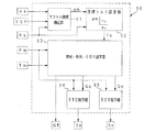
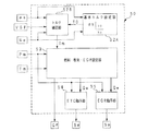
上記ECU50の燃料・吸気・EGR制御に係わる機能は、概略的には、図2に示すように、アクセル開度補正部51、目標トルク設定部52、燃料・吸気・EGR設定部53、電子制御スロットル(ETC)指示部54、EGR指示部55等から構成されている。
【0027】
上記アクセル開度補正部51では、アクセルセンサ12によって検出したアクセル開度αsをエンジン運転状態に応じて補正し、上記目標トルク設定部52で、エンジン回転数Neと補正後のアクセル開度αmとに基づいて目標エンジントルクTeを設定する。
【0028】
上記燃料・吸気・EGR設定部53では、目標エンジントルクTeに対応した基本燃料噴射量Gf及びEGR率を設定し、また、EGRバルブ通過ガス流量設定値(目標値)Qe、スロットル通過空気流量設定値(目標値)Qaを算出する。このEGRバルブ通過ガス流量設定値Qe、スロットル通過空気流量設定値Qaの算出は、例えば、基本燃料噴射量及びEGR率から吸気管内の圧力目標値を空気有効成分分圧とEGRガス有効成分分圧とに分けて設定し、以下の吸気系モデルに従って、空気有効成分分圧の推定値及びEGRガス有効成分分圧の推定値を算出することで行われる。
【0029】
すなわち、上記燃料・吸気・EGR設定部53では、EGRバルブ通過ガス流量設定値Qeを、EGRガス有効成分分圧の推定値とEGRガス有効成分分圧の制御目標値との偏差に基づいて算出するとともに、スロットルバルブ通過空気流量設定値Qaを、空気有効成分分圧の推定値と空気有効成分分圧の制御目標値との偏差、及び、EGRガス中の空気過不足成分に基づいて算出する。
【0030】
尚、有効成分とは、目標値(初期設定値)に呼応するための成分を示し、EGRガス有効成分は、制御空燃比が当量(理論空燃比)であれば、EGRガス中の非空気成分である不活性成分(理論空燃比での既燃ガスに相当する成分;H20,CO2,N2等からなる)と同じ値であるが、制御空燃比がリーンの場合、当量比分の空気を含み、EGRガス中の空気成分に不活性成分を加えた値となる。
【0031】
また、過不足成分は、有効分に対する過不足分を示し、定常状態では目標当量比と排気当量比とが同じであるため、過不足は生じないが、過渡的には、これから制御しようとする目標当量比と現在還流されてくるEGRガスの排気当量比とが一致しないことが多く、目標当量比>排気当量比の場合には、還流されてくるEGRガス中に過剰空気を生じ、目標当量比<排気当量比の場合には、還流されてくるEGRガス中に不足空気を生じる。従って、この過剰・不足空気分をスロットルバルブ・EGRバルブ制御で目標状態に制御するのである。
【0032】
ここで、上記燃料・吸気・EGR設定部53で用いる吸気系モデルは、エンジン1の吸気管2に介装されたスロットルバルブ3を通過する新気分の流量(スロットル通過空気流量)Qaと、排気管4から吸気管2への排気還流管5に介装されたEGRバルブ21を通過するEGRガス流量(EGRバルブ通過ガス流量)Qeとが吸気管2内に供給され、エンジン1のシリンダに流出しているとするモデルであり、スロットル通過空気流量QaとEGRバルブ通過ガス流量Qeとによって吸気管容積を充填する分の空気量を見込むことにより、アクセル操作量とエンジン回転数から設定した目標エンジントルクを過渡的に遅れなく実現することができる。
【0033】
吸気管内の空気有効成分は、スロットルバルブ3を通過する新気分と、EGRバルブ21を通過するEGRガス中の空気過不足成分との和から、シリンダ内へ流入する空気有効成分を除いたものであり、スロットル通過空気流量Qa、EGRガス中の空気過不足成分のEGRバルブ通過流量Qea、吸気管内の空気有効成分のシリンダ流入流量Qso、吸気管容積Vm、吸気管内ガス温度Tm、空気有効成分の気体定数Raを用いて気体の状態方程式を適用すると、吸気管内の空気有効成分分圧Pmoの時間変化量dPmo/dtは、以下の(1)式で表すことができる。
dPmo/dt=(Qa+Qea−Qso)・Ra・Tm/Vm …(1)
【0034】
また、吸気管内のEGRガス有効成分は、EGRバルブ21を通過するEGRガス有効成分からシリンダ内へ流入するEGRガス有効成分を除いたものであり、同様に、吸気管内のEGRガス有効成分分圧Pmeeの時間変化量dPmee/dtは、EGRガス有効成分のEGRバルブ通過流量Qee、EGRガス有効成分のシリンダ流入流量Qsee、EGRガス有効成分の気体定数Reにより、以下の(2)式で表すことができる。
dPmee/dt=(Qee−Qsee)・Re・Tm/Vm …(2)
【0035】
上記(1)式におけるEGRガスの空気過不足成分のEGRバルブ通過流量Qea、上記(2)式におけるEGRガス有効成分のEGRバルブ通過流量Qeeは、EGRバルブ通過ガス流量Qeに、EGRバルブ21入口におけるEGRガスの当量比Φとシリンダ内当量比の初期設定値である目標当量比Φiとの比を適用することにより、それぞれ、以下の(3),(4)式のように表すことができる。
Qea=(1−Φ/Φi)・Qe …(3)
Qee=(Φ/Φi)・Qe …(4)
【0036】
また、上記(1)式における空気有効成分のシリンダ流入流量Qso、上記(2)式におけるEGRガス有効成分のシリンダ流入流量Qseeは、それぞれ、1気筒当たりのストローク容積Vs、体積効率ηv、エンジンの気筒数Lを用いて、以下の(5),(6)式で表すことができる。
Qso=((Pmo・Vs)/(Ra・Tm))・ηv・(Ne・L/120) …(5)
Qsee=((Pmee・Vs)/(Re・Tm))・ηv・(Ne・L/120) …(6)
【0037】
従って、上記(1),(2)式に上記(3)〜(5)式を適用して式中の一部を以下の(7)〜(9)式で示す係数a,ba,beで置き換え、上記(1),(2)式をマトリックス形式で記述すると、以下の(10)式で示すようになり、スロットル通過空気流量Qa、EGRバルブ通過ガス流量Qe、及び、EGRガスの当量比Φと目標当量比Φiとの比に基づいて、吸気管内の状態を空気有効成分分圧Pmoの時間変化量とEGRガス有効成分分圧Pmeeの時間変化量とによって表現することができる。
a =(Vs/Vm)・ηv・(Ne・L/120) …(7)
ba=Ra・Tm/Vm …(8)
be=Re・Tm/Vm …(9)
【0038】
尚、上記吸気系モデルによるEGRバルブ通過ガス流量Qe、スロットル通過空気流量Qaの算出処理については、本出願人による特願平8−253563号に詳述されている。
【0039】
以上により、EGRバルブ通過ガス流量Qe、スロットル通過空気流量Qaを算出すると、ETC指示部54で、マニホルド圧Pmとスロットル通過空気流量設定値Qaとから、スロットルアクチュエータ20に対する操作量としてのスロットルアクチュエータ指示値(ETC指示値)Saを設定してスロットルアクチュエータ20へ出力し、また、EGR指示部34で、マニホルド圧PmとEGRバルブ通過ガス流量設定値Qeとから、EGRバルブ21に対する操作量としてのEGRバルブ指示値Seを設定してEGRバルブ21へ出力する。
【0040】
この場合、アイドル運転領域では、エンジン回転数Neと上記アクセル開度補正部51で補正されたアクセル開度αmとに基づく目標エンジントルクTeに対応してスロットル通過空気流量Qa、基本燃料噴射量Gfが設定され、エンジン回転数Neが目標回転数に制御されるが、アクセルペダルの踏み込みに応じた実アクセル開度αsに対する補正量は、非アイドル運転領域においても維持され、アイドル運転領域と非アイドル運転領域との制御の連続性が確保される。
【0041】
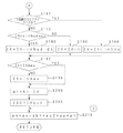
このため、上記アクセル開度補正部51の機能は、図1に示すように、アイドル判定部60、負荷状態判定部61、目標エンジン回転数設定部62、補正量設定部63、補正後アクセル開度算出部64から構成されており、アイドル判定部60で、エンジンが無負荷のアイドル状態を判定し、さらに、負荷状態判定部61で、エアコンプレッサの作動や発電量の増加等の補機類による負荷条件の変化を判定する。
【0042】
そして、アイドル運転状態のとき、目標エンジン回転数設定部62で負荷状態判定部61の判定結果に応じて目標エンジン回転数Nemを設定する。この目標エンジン回転数Nemは、エンジンの暖機状態に応じた目標エンジン回転数Neiに、負荷状態に応じた増加量DNeiを加算したものであり、負荷状態判定部61で負荷増加が無いと判定されたときには、Nem=Neiとなる。
【0043】
さらに、補正量設定部63で、エンジンの暖機状態に応じた補正量αb1や負荷状態に応じた補正量αb2を設定するとともに、目標エンジン回転数Nemと実エンジン回転数Neとの偏差に基づくフィードバック補正量(後述する回転差比例フィードバック補正量と回転差積分フィードバック補正量)αp,αiを設定する。
【0044】
補正後アクセル開度算出部64では、各補正量αb1,αb2,αp,αiを、アクセルセンサ12によって検出した実アクセル開度αsに加算して補正後アクセル開度αmを算出し、この補正後アクセル開度αmを目標トルク設定部52へ出力する。アイドル運転時には、実アクセル開度αsは0であり、実質的に各補正量αb1,αb2,αp,αiの和が補正後アクセル開度αmとして目標トルク設定部52へ出力され、補正後アクセル開度αmとエンジン回転数Neとによって設定される目標エンジントルクTeにより、スロットル通過空気流量Qa、基本燃料噴射量Gfが設定され、エンジン回転数Neが目標エンジン回転数Nemに収束するよう制御される。
【0045】
また、上記補正後アクセル開度算出部64では、アイドル判定部60でアイドル領域から非アイドル領域への移行が判定された場合においても、アイドル運転時に算出した各補正量を保持し、アクセルペダルの踏み込みに応じた実アクセル開度αsに各補正量を加算して補正後アクセル開度αmを算出し、目標トルク設定部52へ出力する。すなわち、アイドル領域及び非アイドル領域において、連続的なエンジン出力制御が行われることになる。
【0046】
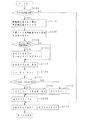
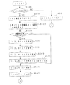
以下、ECU50によるアクセル開度補正処理の詳細について、図3のフローチャートに従って説明する。
【0047】
図1のアクセル開度補正ルーチンでは、まず、ステップS100で現在の運転状態がアイドル判定条件を満足するか否かを調べる。このアイドル判定条件は、例えば、車速センサ11による現在の車速VSPが設定車速VSET(例えば、4km/h)より低く、且つ、アクセルセンサ12のアクセル全閉スイッチがONになっているとき、アイドル運転状態と判定するものであり、アイドル判定条件を満足しないときには、上記ステップS100から後述するステップS210へジャンプし、アイドル判定条件を満足するとき、上記ステップS110からステップS110以降のアイドルスピードコントロール(ISC)制御処理へ進む。
【0048】
尚、アイドル判定条件として、アクセル全閉スイッチがONである条件に代え、アクセルセンサ12による実アクセル開度αsが設定値以下である条件を採用しても良い。
【0049】
ステップS110以降のISC制御処理では、ステップS110で、エンジンの暖機状態に応じてアクセル開度を補正するための暖機補正量αb1を設定するとともに、負荷状態に応じてアクセル開度を補正するための負荷補正量αb2を0に初期設定する。上記暖機補正量αb1は、機械的摩擦損失や燃焼効率が暖機状態によって変化することを補正するためのものであり、例えば冷却水温TWに基づいてマップ参照等により設定される。また、上記負荷補正量αb2は、エアコンの作動や発電量の増加等の補機類の駆動力変動に対応するものである。
【0050】
続くステップS120では、アイドル時の目標エンジン回転数をエンジンの暖機状態に応じて設定し、この暖機状態に応じた目標エンジン回転数Neiを、現時点での目標エンジン回転数Nemとして設定する(Nem=Nei)。暖機状態に応じた目標エンジン回転数Neiは、エンジンの暖機途上でエンジン回転数を暖機完了後よりも高めて暖機促進やアイドル回転数の安定化を図るためのものであり、例えば、冷却水温TWに基づいてマップ参照などにより設定される。
【0051】
その後、ステップS130へ進み、エアコンON等による負荷増加が有るか否かを調べ、負荷増加が無いときには、負荷補正量αb2及び目標エンジン回転数Nemを現状の設定値としたまま(αb2=0、Nem=Nei)ステップS150へジャンプし、負荷増加があるとき、ステップS140で、負荷補正量αb2を所定値αb2xとするとともに、負荷増加に対応して目標エンジン回転数を高めるための増加量DNeiを、暖機状態に応じた目標エンジン回転数Neiに加算して最終的な目標エンジン回転数Nemを設定し(Nem=Nei+DNei)、ステップS150へ進む。
【0052】
ステップS150では、目標エンジン回転数Nemとクランク角センサ10からの信号に基づく現在のエンジン回転数Neとの偏差Nedを算出し(Ned=Nem−Ne)、ステップS160で、目標エンジン回転数Nemと実エンジン回転数Neとの回転数差に比例してアクセル開度をフィードバック補正するための回転差比例フィードバック補正量αpを設定する(αp=Kp・Ned;但し、Kpはフィードバック比例ゲイン)。
【0053】
次に、ステップS170へ進み、目標エンジン回転数Nemと現在のエンジン回転数Neとの偏差Nedの絶対値が設定値Nedmaxを超えているか否かを調べる。そして、│Ned│<Nedmaxのときには、上記ステップS170からステップS180へ進んで、偏差Nedを積分した1制御周期前までの値IX(-1)に、今回の偏差Nedと制御周期dtを乗算した値を加算して積分値IXを更新し(IX=IX(-1)+Ned・dt)、ステップS200へ進む。
【0054】
一方、上記ステップS170において│Ned│≧Nedmaxのときには、上記ステップS170からステップS190へ進み、偏差Nedの積分を停止して1制御周期前の積分値IX(-1)を今回の積分値IXとし(IX=IX(-1))、ステップS200へ進む。
【0055】
ステップS200では、目標エンジン回転数Nemと実エンジン回転数Neとの回転数差の積分値に応じてアクセル開度をフィードバック補正するための回転差積分フィードバック補正量αiを、上記積分値IXにフィードバック積分ゲインKiを乗算して設定し(αi=Ki・IX)、ステップS210で、アクセルセンサ12によって検出したアクセル開度αsに、暖機補正量αb1、負荷補正量αb2、回転差比例フィードバック補正量αp、回転差積分フィードバック補正量αiを加算して補正後アクセル開度αmを求め(αm=αs+αb1+αb2+αp+αi)、ルーチンを抜ける。
【0056】
この場合、上記ステップS100のアイドル判定条件を満足し、ステップS110以降の処理を経て上記ステップS210へ進んだときには、アイドル運転状態で実質的にαs=0であるため、補正後アクセル開度αmは実質的にαm=αb1+αb2+αp+αiとなる。そして、この補正後アクセル開度αmとエンジン回転数Neとによって目標エンジントルクTeが設定され、スロットルバルブ3の開度が制御されて目標エンジン回転数NemへのISC制御が行われる。
【0057】
また、上記ステップS100のアイドル判定条件を満足せず、非アイドル運転状態で上記ステップS210へジャンプしたときには、アイドル状態で設定されて保存された各補正量がアクセルペダルの踏み込み量に応じた実アクセル開度αsに加算され、この補正後アクセル開度αmとエンジン回転数Neとによって設定される目標エンジントルクTeに基づいて、エンジンの出力制御が行われる。
【0058】
この場合、アクセル開度は、基本的にエンジン出力(仕事率)と略比例関係にあるため、以上のアクセル開度補正処理によって得られる結果は、エンジントルクで表現すれば、エンジン回転数が低い程エンジントルクを増加させ、エンジン回転数が高い場合にはエンジントルクの増加量が相対的に少なくなる。
【0059】
すなわち、アイドル時には、エンジン回転数の安定度が高く、エンジンブレーキ等への悪影響も少ない制御とすることができ、且つ、アイドル領域と非アイドル領域とで連続したシンプルで高性能な制御を実現することができる。
【0060】
図5及び図6は本発明の実施の第2形態に係わり、アクセル開度補正ルーチンのフローチャートである。
【0061】
本形態は、前述の第1形態に対し、一旦、ISC制御から抜けて新たにISC制御に入った場合に積分値IXを加算増分し、さらに、積分値IXの大きさに制限を設けるものである。
【0062】
このため、本形態では、第1形態のアクセル開度ルーチン(図3参照)に対し、ISC制御実行の判断や積分値の加算制限処理等を追加している。以下、図5及び図6に示す本形態のアクセル開度補正ルーチンについて説明する。尚、第1形態のアクセル開度補正ルーチンと同様のステップには同じ符号を付して詳細な説明は省略する。
【0063】
本形態のアクセル開度補正ルーチンでは、ステップS100でアイドル判定条件が満足されず、非アイドル運転状態のとき、ステップS100からステップS206へ分岐してISCフラグをクリアした後、補正後アクセル開度αmを算出するステップS210へジャンプし、アイドル判定条件を満足するときには、第1形態と同様、ステップS110〜S160で、暖機補正量αb1、負荷補正量αb2、目標エンジン回転数Nem、回転差比例フィードバック補正量αpを設定した後、ステップS160からステップS165へ進み、1回前のISCフラグがクリアされているか否かを調べる。
【0064】
そして、ISCフラグがクリアされていないときには、上記ステップS165からステップS170へ進み、第1形態と同様、目標エンジン回転数Nemと現在のエンジン回転数Neとの偏差Nedの絶対値が設定値Nedmaxを超えているか否かを調べ、その結果に応じてステップS180あるいはステップS190で積算値IXを更新する(IX=IX(-1)+Ned・dt、IX=IX(-1))。
【0065】
一方、上記ステップS165でISCフラグがクリアされているとき、すなわち、一旦ISC制御から抜けた後、新たにISC制御条件に入った場合には、上記ステップS165からステップS166へ分岐し、1制御周期前の積分値IX(-1)に増分値IXoを加算して今回の積分値IXを設定する(IX=IX(-1)+IXo)。この増分値IXoは、一定時間中は再度加算条件が成立しても加算しない、あるいは、増分値IXoを加算する条件としてエンジン回転数Ne等の運転条件に対するヒステリシスを設ける等して、加算の重複を回避することが望ましく、アイドル領域と非アイドル領域とを短時間で行き来するような場合、エンジン回転数の低下不良を防止することができる。
【0066】
上記ステップS180,S190,S166の各ステップで積分値IXを設定した後は、各ステップからステップS195へ進み、積分値IXが積分制限値IXmaxを超えているか否かを調べる。そして、IX<IXmaxのときには、ステップS195からステップS200へジャンプし、IX≧IXmaxのとき、ステップS195からステップS196へ進んで積分値IXを積分制限値IXmaxに飽和させ(IX=IXmax)、ステップS200へ進む。ステップS200では回転差積分フィードバック補正量αiを設定し、その後、ステップS205でISCフラグをセットすると、ステップS210で補正後アクセル開度αmを算出する。
【0067】
本形態では、新たにISC制御条件に入ったとき、積分値IXを増分値IXoだけ加算設定するため、目標エンジン回転数までの回転数低下を緩慢にする、いわゆるダッシュポット効果を得ることができ、また、積分値IXに制限を設けることで、エンジン回転数が目標エンジン回転数と大きく異なる時点での過度な積分を防止し、ハンチングを抑制することができる。
【0068】
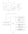
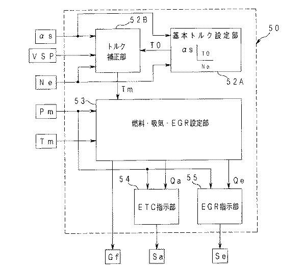
図7〜図11は本発明の実施の第3形態に係わり、図7は燃料・吸気・EGR制御機能のブロック図、図8はトルク補正部のブロック図、図9及び図10はトルク補正ルーチンのフローチャート、図11はトルク補正量の特性図である。
【0069】
本形態は、前述の各形態に対し、アクセルセンサ12によって検出したアクセル開度αs(すなわち運転者の操作に応じたアクセル開度)を補正せず、このアクセル開度αsとエンジン回転数Neとに基づいて基本トルク(目標エンジントルクの初期値)T0を設定した後、この基本トルクT0に、負荷の作動による消費トルクを補うトルク補正量を加算・補正してエンジン出力トルクを一定に制御するものである。
【0070】
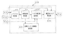
このため、本形態の燃料・吸気・EGR制御に係わる機能構成は、図7に示すように、前述の第1形態に対し、目標トルク設定部52に代えて基本トルク設定部52A、アクセル開度補正部51に代えてトルク補正部52Bを備え、トルク補正部52Bの機能は、図8に示すように、前述の第1形態に対し、補正量設定部63に代えてトルク補正量設定部63A、補正後アクセル開度算出部64に代えて補正後トルク算出部64Aを備えた構成となっている。
【0071】
すなわち、本形態では、基本トルク設定部52Aでエンジン回転数Neとアクセルセンサ12によって検出したアクセル開度αsとに基づいて基本トルクT0を設定し、この基本トルクT0をトルク補正部52Bへ出力する。トルク補正部52Bでは、アイドル判定部60でエンジンが無負荷のアイドル状態を判定するとともに、負荷状態判定部61でエアコンプレッサの作動や発電量の増加等の補機類による負荷条件の変化を判定し、アイドル運転状態のとき、目標エンジン回転数設定部62で負荷状態判定部61の判定結果に応じて目標エンジン回転数Nemを設定し、さらに、トルク補正量設定部63Aで、エンジンの暖機状態に応じたトルク補正量Tb1、負荷状態に応じたトルク補正量Tb2,Tb3を設定するとともに、目標エンジン回転数Nemと実エンジン回転数Neとの偏差に基づくトルクフィードバック補正量(後述する回転差比例トルクフィードバック補正量と回転差積分トルクフィードバック補正量)Tp,Tiを設定する。そして、補正後トルク算出部64Aで、各補正量Tb1,Tb2,Tb3,Tp,Tiを基本トルクT0に加算して補正後トルクTmを算出し、燃料・吸気・EGR設定部53へ出力する。燃料・吸気・EGR設定部53では、補正後トルクTmに対応した基本燃料噴射量Gf及びEGR率を設定し、EGRバルブ通過ガス流量設定値Qe、スロットル通過空気流量設定値Qaを算出する。
【0072】
この場合、前述の第1形態と同様、アイドル領域及び非アイドル領域において連続的なエンジン出力制御を行うべく、上記補正後トルク算出部64Aでは、アイドル判定部60でアイドル領域から非アイドル領域への移行が判定された場合においても、アイドル運転時に算出した各補正量を保持し、基本トルクT0に各補正量を加算して補正後トルクTmを算出し、燃料・吸気・EGR設定部53へ出力する。
【0073】
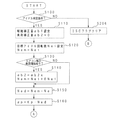
上記トルク補正部52Bにおけるトルク補正は、具体的には、図9及び図10に示すトルク補正ルーチンによって行われる。以下、このトルク補正ルーチンについて説明する。
【0074】
このルーチンでは、ステップS300で第1形態と同様のアイドル判定条件を満足するか否かを調べ、アイドル判定条件を満足せずに非アイドル運転状態のとき、ステップS490でISCフラグをクリアした後、補正後トルクTmを算出するステップS500へジャンプし、アイドル判定条件を満足するときには、ステップS300からステップS310以降へ進む。
【0075】
ステップS310では、エンジンの暖機状態に応じたトルク補正量Tb1を、例えば冷却水温TWに基づいてマップ参照等により設定し、ステップS320で、アイドル時の目標エンジン回転数をエンジンの暖機状態に応じて設定し、この暖機状態に応じた目標エンジン回転数Neiを現時点での目標エンジン回転数Nemとして設定する(Nem=Nei)。
【0076】
次に、ステップS330へ進み、エアコンON等による補機類の作動状態の変化があるか否かを調べ、補機類の作動状態の変化がないときには、目標エンジン回転数Nemを現状の設定値としたまま(Nem=Nei)ステップS370へジャンプし、補機類の作動状態に変化があるとき、ステップS340〜S360で、負荷状態に応じたトルク補正量を、補機類の消費トルクの変化に応じたトルク補正量Tb2と、補機類の消費仕事率(消費馬力)の変化に応じたトルク補正量Tb3とに分けて設定する。
【0077】
すなわち、各負荷のエンジン出力トルクへの影響は負荷毎に相違し、エンジン回転数に応じて変化する成分つまり馬力に直接影響する成分と、トルクに直接影響する成分とが重合し、両成分の影響比率は、それぞれの負荷で相違する。従って、複数の負荷が作動しているときには、それぞれの負荷によるトルク影響分(トルク補正量Tb2)及び馬力影響分(トルク補正量Tb3)を考慮し、負荷毎のトルク補正量を設定する。尚、図11は、エンジン回転数とトルク補正量(Tb2,Tb3)との関係を模式的に示したものである。
【0078】
詳細には、ステップS340で、補機類の消費トルクの変化に応じたトルク補正量Tb2(トータル量)を設定するとともに、この消費トルクの変化に対応して目標エンジン回転数を高めるための増加量DNei2を設定し、ステップS350で、補機類の消費仕事率(消費馬力)の変化に応じて仕事率補正量Wb3(トータル量)を求め、さらに、この消費仕事率の変化に対応して目標エンジン回転数を高めるための増加量DNei3を設定する。
【0079】
次いで、ステップS360へ進み、仕事率補正量Wb3とエンジン回転数Neとに基づいてマップ参照等により補機類の消費馬力の変化に応じたトルク補正量Tb3(トータル量)を設定すると、ステップS370で、目標エンジン回転数の増加分DNei2,DNei3を、暖機状態に応じた目標エンジン回転数Neiに加算して最終的な目標エンジン回転数Nemを設定し(Nem=Nei+DNei2+DNei3)、ステップS380以降へ進む。
【0080】
尚、ステップS340〜S360では、トルク補正量Tb2,Tb3を個別に算出しているが、両補正量Tb2,Tb3の合算値をエンジン回転数毎にマップ上に設定しても良い。
【0081】
ステップS380以降は、第1,2形態と同様の処理であり、ステップS380で目標エンジン回転数Nemと現在のエンジン回転数Neとの偏差Nedを算出し(Ned=Nem−Ne)、ステップS390で目標エンジン回転数Nemと実エンジン回転数Neとの回転数差に比例してトルク補正をフィードバックするための回転差比例トルクフィードバック補正量Tpを設定(Tp=KTp・Ned;但し、KTpはフィードバック比例ゲイン)した後、ステップS400へ進んで1回前のISCフラグがクリアされているか否かを調べる。
【0082】
そして、ISCフラグがクリアされているとき、すなわち、新たにISC制御条件に入った場合には、上記ステップS400からステップS410へ分岐し、偏差Nedを積分した1制御周期前の値IX(-1)に増分値IXoを加算して今回の積分値IXを設定する(IX=IX(-1)+IXo)。
【0083】
一方、上記ステップS400でISCフラグがクリアされていないときには、上記ステップS400からステップS420へ進み、目標エンジン回転数Nemと現在のエンジン回転数Neとの偏差Nedの絶対値が設定値Nedmaxを超えているか否かを調べ、その結果に応じてステップS430あるいはステップS440で積算値IXを更新する(IX=IX(-1)+Ned・dt、IX=IX(-1))。
【0084】
上記ステップS410,S420,S430の各ステップで積分値IXを設定した後は、各ステップからステップS450へ進み、積分値IXが積分制限値IXmaxを超えているか否かを調べる。そして、IX<IXmaxのときには、ステップS450からステップS470へジャンプし、IX≧IXmaxのとき、ステップS450からステップS460へ進んで積分値IXを積分制限値IXmaxに飽和させ(IX=IXmax)、ステップS470へ進む。
【0085】
ステップS470では、目標エンジン回転数Nemと実エンジン回転数Neとの回転数差の積分値に応じてトルク補正をフィードバックするための回転差積分フィードバック補正量Tiを、上記積分値IXにフィードバック積分ゲインKTiを乗算して設定し(Ti=KTi・IX)、その後、ステップS480でISCフラグをセットすると、ステップS500で、トルク補正量Tb1,Tb2,Tb3、回転差比例トルクフィードバック補正量Tp、回転差積分トルクフィードバック補正量Tiを基本トルクT0に加算して補正後トルクTmを求め(Tm=T0+Tb1+Tb2+Tb3+Tp+Ti)、ルーチンを抜ける。
【0086】
本形態では、前述の第1,2形態の効果に加え、補機類の消費トルクの変化や消費仕事率の変化に応じて適切に対応することができ、アイドル運転時の回転数安定性が高く、エンジンブレーキ等への悪影響も少ない。
【0087】
尚、以上の各形態では、スロットルアクチュエータ20によってスロットルバルブ3を駆動し、アイドル領域から非アイドル領域までの全運転領域における空気量を制御する例について説明したが、スロットルバルブ3をバイパスするバイパス通路に空気量を調整するISCバルブを介装し、アイドル判定時には、このISCバルブを介して要求される空気量を確保するようにしても良く、アイドル領域と非アイドル領域とでISCバルブからスロットルバルブへ制御対象が変わっても、空気量制御の連続性を確保することができる。
【0088】
【発明の効果】
以上説明したように本発明によれば、アイドル領域での安定性を確保すると共にアイドル領域と非アイドル領域との制御の連続性を確保し、シンプルで高性能な制御を実現することができる等優れた効果が得られる。
【図面の簡単な説明】
【図1】本発明の実施の第1形態に係わり、アクセル開度補正部のブロック図
【図2】同上、燃料・吸気・EGR制御機能のブロック図
【図3】同上、アクセル開度補正ルーチンのフローチャート
【図4】同上、エンジン制御系の概略構成図
【図5】本発明の実施の第2形態に係わり、アクセル開度補正ルーチンのフローチャート
【図6】同上、アクセル開度補正ルーチンのフローチャート(続き)
【図7】本発明の実施の第3形態に係わり、燃料・吸気・EGR制御機能のブロック図
【図8】同上、トルク補正部のブロック図
【図9】同上、トルク補正ルーチンのフローチャート
【図10】同上、トルク補正ルーチンのフローチャート(続き)
【図11】同上、トルク補正量の特性図
【符号の説明】
1 …エンジン
3 …スロットルバルブ
20 …スロットルアクチュエータ
51 …アクセル開度補正部
52 …目標トルク設定部
52A…基本トルク設定部
52B…トルク補正部
53 …燃料・吸気・EGR設定部[0001]
BACKGROUND OF THE INVENTION
The present invention relates to an engine control device that sets an engine output target value based on an accelerator opening and an engine speed, and controls a fuel amount and an air amount supplied to the engine in accordance with the output target value.
[0002]
[Prior art]
Recently, a so-called electronically controlled throttle type engine in which an actuator is connected to a throttle valve and the throttle opening is electronically controlled via this actuator has been put into practical use. From the accelerator opening and the engine speed, The engine output target value is set, the fuel injection amount is controlled according to the set main power target value, and the intake air amount is controlled by adjusting the throttle opening.
[0003]
For example, the applicant previously determined a target output condition based on the accelerator opening and the engine speed in Japanese Patent Application No. 8-253563, and based on this target output condition, the throttle valve, EGR valve, fuel injection amount were determined. In this technology, the ignition timing etc. are controlled forward at the same time. This technology improves the responsiveness to the driver's required output while dealing with a large change in air-fuel ratio and large EGR rate. Performance can be obtained.
[0004]
[Problems to be solved by the invention]
However, since the accelerator opening is normally 0 (the amount of depression of the accelerator pedal is 0) during idle operation, it must be separated from control in the non-idle region by using conventional idle control during idle operation. In addition to the complexity of the control system, there is a problem that continuity in control is lost and smoothness is lost.
[0005]
In this case, in the conventional idle control, the throttle valve and the flow rate adjustment valve (throttle bypass valve) interposed in the bypass passage that bypasses the throttle valve are controlled based on the information on the engine speed, and the resulting air The fuel injection amount and ignition timing are controlled by detecting the change in the amount of fuel, and the process goes through the process of engine speed reduction → throttle (bypass) operation → air amount change → fuel injection amount / ignition timing change → engine output change. For this reason, there is a large time delay from when the engine speed changes to when the engine output actually changes, leading to instability of the idling speed and deterioration of feeling.
[0006]
The present invention has been made in view of the above circumstances, and when performing engine output control based on the accelerator opening and the engine speed, while ensuring the stability in the idle region, the idle region and the non-idle region It is an object of the present invention to provide an engine control device that can ensure continuity of control and can realize simple and high-performance control.
[0007]
[Means for Solving the Problems]
According to the first aspect of the present invention, the accelerator opening according to the operation of the driver is calculated by calculating the correction amount based on the warm-up state and the load state of the engine, and the target engine speed and the actual engine speed during idle operation. Correct by the correction amount based on the deviation, Each of the above Means for maintaining the correction amount even during non-idle operation, means for setting the engine output target value based on the corrected accelerator opening and engine speed, and supplying the engine to the engine corresponding to the output target value And means for controlling the amount of fuel and the amount of air.
[0008]
According to a second aspect of the present invention, there is provided means for setting an engine output target value based on an accelerator opening and an engine speed according to a driver's operation, and the output target value is determined based on an engine warm-up state and a load. Correction based on the correction amount based on the state and the correction amount based on the deviation between the target engine speed and the actual engine speed during idle operation, Each of the above It is characterized by comprising means for maintaining the correction amount even during non-idle operation, and means for controlling the amount of fuel and air supplied to the engine in accordance with the corrected output target value.
[0009]
According to a third aspect of the present invention, in the first or second aspect of the invention, the correction amount based on the deviation is divided into a correction amount proportional to the deviation and a correction amount proportional to the integral value of the deviation. It is characterized by setting.
[0010]
The invention described in
[0011]
The invention described in
[0012]
A sixth aspect of the invention is characterized in that, in the invention according to any one of the third, fourth, and fifth aspects, when the non-idle operation is shifted to the idle operation, a predetermined increment value is added to the integral value. And
[0013]
A seventh aspect of the invention is characterized in that, in the sixth aspect of the invention, the increment value is not re-added until a predetermined time elapses after the increment value is added.
[0014]
The invention described in claim 8 is characterized in that, in the invention described in
[0015]
That is, in the engine control apparatus according to the first aspect of the present invention, the accelerator opening corresponding to the driver's operation is determined by the correction amount based on the warm-up state and the load state of the engine, and the target engine speed during idle operation. The engine output target value is set based on the corrected accelerator opening and engine speed, and supplied to the engine corresponding to this output target value. Control the amount of fuel and the amount of air.
[0016]
In the engine control apparatus according to the second aspect of the present invention, an engine output target value is set based on the accelerator opening and the engine speed according to the operation of the driver, and the output target value is Correction is made based on the correction amount based on the warm-up state and the load state, and the correction amount based on the deviation between the target engine speed and the actual engine speed during idle operation, and supplied to the engine corresponding to the corrected output target value Control the amount of fuel and the amount of air.
[0017]
In this case, the correction amount of the accelerator opening in the invention of
[0018]
Further, the correction amount based on the deviation between the target engine speed and the actual engine speed during idling can be set separately as a correction amount proportional to the deviation and a correction amount proportional to the integral value of the deviation, When the deviation is greater than or equal to the set value, it is desirable to maintain the integrated value at the previous value or limit the integrated value to the set range.
[0019]
Furthermore, it is desirable to add a predetermined increment value to the integral value when shifting from the non-idle operation to the idle operation, and the increment value is restarted until a certain time elapses after the addition of the increment value. It is desirable not to add, or to add an increment value according to hysteresis set according to operating conditions.
[0020]
DETAILED DESCRIPTION OF THE INVENTION
Embodiments of the present invention will be described below with reference to the drawings. 1 to 4 relate to a first embodiment of the present invention, FIG. 1 is a block diagram of an accelerator opening correction unit, FIG. 2 is a block diagram of a fuel / intake / EGR control function, and FIG. 3 is an accelerator opening correction. FIG. 4 is a schematic configuration diagram of an engine control system.
[0021]
In FIG. 4,
[0022]
The
[0023]
Sensors connected to the
[0024]
The actuators connected to the
[0025]
The
[0026]
The functions of the
[0027]
The accelerator
[0028]
The fuel / intake / EGR setting unit 53 sets the basic fuel injection amount Gf and the EGR rate corresponding to the target engine torque Te, and also sets the EGR valve passage gas flow rate setting value (target value) Qe and the throttle passage air flow rate setting. A value (target value) Qa is calculated. The calculation of the EGR valve passage gas flow rate setting value Qe and the throttle passage air flow rate setting value Qa is performed by, for example, calculating the target air pressure and the EGR gas effective component partial pressure from the basic fuel injection amount and the EGR rate. And the estimated value of the effective air component partial pressure and the estimated value of the EGR gas effective component partial pressure are calculated according to the following intake system model.
[0029]
That is, the fuel / intake / EGR setting unit 53 calculates the EGR valve passage gas flow rate setting value Qe based on the deviation between the estimated value of the EGR gas effective component partial pressure and the control target value of the EGR gas effective component partial pressure. At the same time, the throttle valve passing air flow rate set value Qa is calculated based on the deviation between the estimated value of the effective air component partial pressure and the control target value of the effective air component partial pressure, and the excess or insufficient air component in the EGR gas. .
[0030]
The effective component indicates a component for responding to the target value (initial setting value). The EGR gas effective component is a non-air component in the EGR gas if the control air-fuel ratio is equivalent (theoretical air-fuel ratio). Is the same value as the inert component (the component corresponding to the burned gas at the stoichiometric air-fuel ratio; composed of H20, CO2, N2, etc.), but when the control air-fuel ratio is lean, it contains air for an equivalent ratio, A value obtained by adding an inert component to an air component in the EGR gas.
[0031]
The excess / deficiency component indicates the excess / deficiency with respect to the effective component, and since the target equivalent ratio and the exhaust equivalent ratio are the same in the steady state, the excess / deficiency does not occur. In many cases, the target equivalent ratio does not match the exhaust equivalent ratio of the currently recirculated EGR gas. If target equivalent ratio> exhaust equivalent ratio, excess air is generated in the recirculated EGR gas, and the target equivalent If ratio <exhaust equivalent ratio, insufficient air is generated in the recirculated EGR gas. Therefore, the excess / deficient air is controlled to the target state by the throttle valve / EGR valve control.
[0032]
Here, the intake system model used in the fuel / intake / EGR setting unit 53 includes a flow rate of fresh air (throttle passage air flow rate) Qa passing through the
[0033]
The effective air component in the intake pipe is obtained by removing the effective air component flowing into the cylinder from the sum of the fresh air passing through the
dPmo / dt = (Qa + Qea−Qso) · Ra · Tm / Vm (1)
[0034]
The EGR gas effective component in the intake pipe is obtained by removing the EGR gas effective component flowing into the cylinder from the EGR gas effective component passing through the
dPmee / dt = (Qee−Qsee) · Re · Tm / Vm (2)
[0035]
The EGR valve passage flow rate Qea of the excess or insufficient air component of the EGR gas in the above equation (1), and the EGR valve passage flow rate Qee of the EGR gas effective component in the above equation (2) are the EGR valve passage gas flow rate Qe and the
Qea = (1-Φ / Φi) · Qe (3)
Qee = (Φ / Φi) ・ Qe (4)
[0036]
The cylinder inflow rate Qso of the effective air component in the above equation (1) and the cylinder inflow rate Qsee of the EGR gas effective component in the above equation (2) are respectively the stroke volume Vs per cylinder, the volume efficiency ηv, Using the number of cylinders L, it can be expressed by the following equations (5) and (6).
Qso = ((Pmo · Vs) / (Ra · Tm)) · ηv · (Ne · L / 120) (5)
Qsee = ((Pmee · Vs) / (Re · Tm)) · ηv · (Ne · L / 120) (6)
[0037]
Accordingly, the above equations (3) to (5) are applied to the above equations (1) and (2), and a part of the equations are expressed by the coefficients a, ba, and be expressed by the following equations (7) to (9). If the above equations (1) and (2) are described in a matrix format, the following equation (10) is obtained, and the equivalent ratio of the throttle-passing air flow rate Qa, EGR-valve passing gas flow rate Qe, and EGR gas: Based on the ratio between Φ and the target equivalent ratio Φi, the state in the intake pipe can be expressed by the time change amount of the air effective component partial pressure Pmo and the time change amount of the EGR gas effective component partial pressure Pmee.
a = (Vs / Vm) · ηv · (Ne · L / 120) (7)
ba = Ra · Tm / Vm (8)
be = Re · Tm / Vm (9)
[0038]
The calculation processing of the EGR valve passage gas flow rate Qe and the throttle passage air flow rate Qa by the intake system model is described in detail in Japanese Patent Application No. 8-253563 by the present applicant.
[0039]
When the EGR valve passage gas flow rate Qe and the throttle passage air flow rate Qa are calculated as described above, the
[0040]
In this case, in the idle operation region, the throttle passage air flow rate Qa and the basic fuel injection amount Gf correspond to the target engine torque Te based on the engine speed Ne and the accelerator opening degree αm corrected by the accelerator opening
[0041]
For this reason, as shown in FIG. 1, the functions of the accelerator
[0042]
When the engine is in the idling state, the target engine speed setting unit 62 sets the target engine speed Nem according to the determination result of the load state determination unit 61. This target engine speed Nem is obtained by adding the increase amount DNei according to the load state to the target engine speed Nei according to the warm-up state of the engine, and the load state determination unit 61 determines that there is no load increase. When it is done, Nem = Nei.
[0043]
Further, the correction
[0044]
The corrected accelerator opening
[0045]
Further, the corrected accelerator opening
[0046]
Hereinafter, the details of the accelerator opening correction process by the
[0047]
In the accelerator opening correction routine of FIG. 1, first, in step S100, it is checked whether or not the current operation state satisfies the idle determination condition. The idle determination condition is, for example, when the current vehicle speed VSP by the vehicle speed sensor 11 is lower than a set vehicle speed VSET (for example, 4 km / h) and the accelerator fully closed switch of the accelerator sensor 12 is ON. When the idle determination condition is not satisfied, the process jumps from step S100 to step S210, which will be described later. When the idle determination condition is satisfied, idle speed control (ISC) from step S110 to step S110 onward is performed. Proceed to the control process.
[0048]
As an idle determination condition, instead of the condition that the accelerator fully closed switch is ON, a condition that the actual accelerator opening αs by the accelerator sensor 12 is equal to or less than a set value may be adopted.
[0049]
In the ISC control process after step S110, in step S110, the warm-up correction amount αb1 for correcting the accelerator opening according to the warm-up state of the engine is set, and the accelerator opening is corrected according to the load state. Therefore, the load correction amount αb2 is initialized to zero. The warm-up correction amount αb1 is used to correct changes in mechanical friction loss and combustion efficiency depending on the warm-up state, and is set, for example, by referring to a map based on the cooling water temperature TW. The load correction amount αb2 corresponds to fluctuations in the driving force of auxiliary equipment such as the operation of an air conditioner and an increase in the amount of power generation.
[0050]
In the subsequent step S120, the target engine speed at idling is set according to the warm-up state of the engine, and the target engine speed Nei according to the warm-up state is set as the current target engine speed Nem ( Nem = Nei). The target engine speed Nei corresponding to the warm-up state is for increasing the engine speed during warm-up of the engine after completion of warm-up to promote warm-up and stabilize the idle speed. Further, it is set by referring to the map based on the cooling water temperature TW.
[0051]
Thereafter, the process proceeds to step S130, where it is checked whether or not there is an increase in load due to the air conditioner ON or the like. If there is no increase in load, the load correction amount αb2 and the target engine speed Nem are kept at the current set values (αb2 = 0, Nem = Nei) Jump to step S150, and when there is an increase in load, in step S140, the load correction amount αb2 is set to a predetermined value αb2x, and an increase amount DNei for increasing the target engine speed corresponding to the increase in load is set. The final target engine speed Nem is set by adding to the target engine speed Nei corresponding to the warm-up state (Nem = Nei + DNei), and the process proceeds to step S150.
[0052]
In step S150, a deviation Ned between the target engine speed Nem and the current engine speed Ne based on the signal from the crank angle sensor 10 is calculated (Ned = Nem−Ne). In step S160, the target engine speed Nem is calculated. A rotational difference proportional feedback correction amount αp for feedback correction of the accelerator opening is set in proportion to the rotational speed difference from the actual engine rotational speed Ne (αp = Kp · Ned; where Kp is a feedback proportional gain).
[0053]
Next, the process proceeds to step S170, and it is checked whether or not the absolute value of the deviation Ned between the target engine speed Nem and the current engine speed Ne exceeds the set value Nedmax. When | Ned | <Nedmax, the process proceeds from step S170 to step S180, and the value IX (-1) up to one control period before integrating the deviation Ned is multiplied by the current deviation Ned and the control period dt. The integrated value IX is updated by adding the values (IX = IX (−1) + Ned · dt), and the process proceeds to step S200.
[0054]
On the other hand, when | Ned | ≧ Nedmax in step S170, the process proceeds from step S170 to step S190, the integration of the deviation Ned is stopped, and the integral value IX (−1) one control period before is set as the current integral value IX. (IX = IX (-1)), the process proceeds to step S200.
[0055]
In step S200, the rotational difference integral feedback correction amount αi for feedback correction of the accelerator opening in accordance with the integral value of the rotational speed difference between the target engine rotational speed Nem and the actual engine rotational speed Ne is fed back to the integral value IX. The integral gain Ki is set by multiplication (αi = Ki · IX). In step S210, the accelerator opening αs detected by the accelerator sensor 12 is added to the warm-up correction amount αb1, the load correction amount αb2, and the rotation difference proportional feedback correction amount. The corrected accelerator opening αm is obtained by adding αp and the rotation difference integral feedback correction amount αi (αm = αs + αb1 + αb2 + αp + αi), and the routine is exited.
[0056]
In this case, when the idle determination condition of step S100 is satisfied and the process proceeds to step S210 through the processing after step S110, the corrected accelerator opening αm is substantially equal to αs = 0 in the idle operation state. It becomes substantially αm = αb1 + αb2 + αp + αi. Then, the target engine torque Te is set by the corrected accelerator opening αm and the engine speed Ne, the opening of the
[0057]
Further, when the idle determination condition of step S100 is not satisfied and the routine jumps to step S210 in the non-idle operation state, each correction amount set and stored in the idle state is an actual accelerator according to the depression amount of the accelerator pedal. The engine output is controlled based on the target engine torque Te that is added to the opening degree αs and is set by the corrected accelerator opening degree αm and the engine speed Ne.
[0058]
In this case, the accelerator opening is basically in a proportional relationship with the engine output (power), and therefore the result obtained by the accelerator opening correction process described above can be expressed in terms of engine torque with a low engine speed. When the engine torque is increased and the engine speed is high, the increase amount of the engine torque becomes relatively small.
[0059]
In other words, during idling, the engine speed can be controlled with high stability and less adverse effects on engine braking, etc., and simple and high-performance control can be realized continuously in the idle and non-idle areas. be able to.
[0060]
5 and 6 are flowcharts of an accelerator opening correction routine according to the second embodiment of the present invention.
[0061]
In this embodiment, in contrast to the first embodiment described above, when the ISC control is temporarily exited and the ISC control is newly entered, the integral value IX is added and incremented, and the size of the integral value IX is limited. is there.
[0062]
For this reason, in this embodiment, the determination of the ISC control execution, the integral value addition limiting process, and the like are added to the accelerator opening routine (see FIG. 3) of the first embodiment. Hereinafter, the accelerator opening correction routine of the present embodiment shown in FIGS. 5 and 6 will be described. In addition, the same code | symbol is attached | subjected to the step similar to the accelerator opening correction routine of a 1st form, and detailed description is abbreviate | omitted.
[0063]
In the accelerator opening correction routine of this embodiment, when the idle determination condition is not satisfied in step S100 and the non-idle operation state is established, the process branches from step S100 to step S206 to clear the ISC flag, and then the corrected accelerator opening αm When step S210 is calculated and the idle determination condition is satisfied, the warm-up correction amount αb1, the load correction amount αb2, the target engine speed Nem, the rotation difference proportional feedback are performed in steps S110 to S160 as in the first embodiment. After the correction amount αp is set, the process proceeds from step S160 to step S165 to check whether or not the previous ISC flag is cleared.
[0064]
When the ISC flag is not cleared, the process proceeds from step S165 to step S170, and the absolute value of the deviation Ned between the target engine speed Nem and the current engine speed Ne is equal to the set value Nedmax as in the first embodiment. In step S180 or step S190, the integrated value IX is updated in accordance with the result (IX = IX (-1) + Ned · dt, IX = IX (-1)).
[0065]
On the other hand, when the ISC flag is cleared in step S165, that is, when the ISC control condition is newly entered after exiting from ISC control, the process branches from step S165 to step S166, and one control cycle is performed. The increment value IXo is added to the previous integral value IX (-1) to set the current integral value IX (IX = IX (-1) + IXo). This increment value IXo is not added even if the addition condition is satisfied again for a certain period of time, or as a condition for adding the increment value IXo, a hysteresis is provided for the operating condition such as the engine speed Ne, etc. It is desirable to avoid this, and in the case of going back and forth between the idle region and the non-idle region in a short time, it is possible to prevent a decrease in the engine speed.
[0066]
After setting the integral value IX in each of the above steps S180, S190, and S166, the process proceeds from each step to step S195 to check whether the integral value IX exceeds the integral limit value IXmax. When IX <IXmax, the routine jumps from step S195 to step S200. When IX ≧ IXmax, the routine proceeds from step S195 to step S196, where the integral value IX is saturated to the integral limit value IXmax (IX = IXmax), and step S200. Proceed to In step S200, the rotational difference integral feedback correction amount αi is set. After that, when the ISC flag is set in step S205, the corrected accelerator opening αm is calculated in step S210.
[0067]
In this embodiment, when the ISC control condition is newly entered, the integral value IX is added and set by the increment value IXo, so that a so-called dashpot effect can be obtained that slows down the speed reduction to the target engine speed. In addition, by providing a limit on the integral value IX, excessive integration at a time when the engine speed is significantly different from the target engine speed can be prevented, and hunting can be suppressed.
[0068]
7 to 11 relate to a third embodiment of the present invention, FIG. 7 is a block diagram of a fuel / intake / EGR control function, FIG. 8 is a block diagram of a torque correction unit, and FIGS. 9 and 10 are torque correction routines. FIG. 11 is a characteristic diagram of the torque correction amount.
[0069]
The present embodiment does not correct the accelerator opening αs detected by the accelerator sensor 12 (that is, the accelerator opening according to the driver's operation) with respect to each of the above-described forms, and this accelerator opening αs and the engine speed Ne Is set to the basic torque (initial value of the target engine torque) T0, and then the engine output torque is controlled to be constant by adding and correcting a torque correction amount that compensates for the consumed torque due to the operation of the load to the basic torque T0. Is.
[0070]
For this reason, as shown in FIG. 7, the functional configuration relating to the fuel / intake / EGR control of the present embodiment is different from the above-described first embodiment in that a basic torque setting unit 52A, accelerator opening degree is used instead of the target
[0071]
That is, in this embodiment, the basic torque T0 is set based on the engine speed Ne and the accelerator opening degree αs detected by the accelerator sensor 12 by the basic torque setting unit 52A, and this basic torque T0 is output to the torque correction unit 52B. . In the torque correction unit 52B, the
[0072]
In this case, in the same manner as in the first embodiment described above, the corrected
[0073]
Specifically, the torque correction in the torque correction unit 52B is performed by a torque correction routine shown in FIGS. Hereinafter, this torque correction routine will be described.
[0074]
In this routine, it is checked in step S300 whether or not the same idle determination condition as in the first embodiment is satisfied. When the idle determination condition is not satisfied and the non-idle operation state is satisfied, the ISC flag is cleared in step S490. The process jumps to step S500 for calculating the corrected torque Tm, and when the idle determination condition is satisfied, the process proceeds from step S300 to step S310.
[0075]
In step S310, a torque correction amount Tb1 corresponding to the engine warm-up state is set by referring to a map or the like based on the coolant temperature TW, for example, and in step S320, the target engine speed during idling is set to the engine warm-up state. The target engine speed Nei corresponding to this warm-up state is set as the current target engine speed Nem (Nem = Nei).
[0076]
Next, the process proceeds to step S330, in which it is checked whether or not there is a change in the operating state of the auxiliary equipment due to the air conditioner ON or the like. (Nem = Nei) Jump to step S370, and when there is a change in the operating state of the accessories, the torque correction amount corresponding to the load state is changed in steps S340 to S360, and the change in the consumption torque of the auxiliary machinery And a torque correction amount Tb2 corresponding to a change in the power consumption (power consumption) of the auxiliary machinery.
[0077]
In other words, the effect of each load on the engine output torque differs depending on the load, and the component that changes according to the engine speed, that is, the component that directly affects the horsepower, and the component that directly affects the torque are superposed. The impact ratio is different for each load. Therefore, when a plurality of loads are operating, the torque correction amount for each load is set in consideration of the torque influence (torque correction amount Tb2) and the horsepower influence (torque correction amount Tb3) due to each load. FIG. 11 schematically shows the relationship between the engine speed and the torque correction amount (Tb2, Tb3).
[0078]
More specifically, in step S340, a torque correction amount Tb2 (total amount) corresponding to a change in consumption torque of the auxiliary equipment is set, and an increase for increasing the target engine speed in response to the change in consumption torque. The amount DNei2 is set, and in step S350, the power correction amount Wb3 (total amount) is obtained in accordance with the change in the power consumption (power consumption) of the auxiliary machines, and further, the change in the power consumption is responded to. An increase amount DNei3 for increasing the target engine speed is set.
[0079]
Next, the process proceeds to step S360, and when the torque correction amount Tb3 (total amount) corresponding to the change in the consumed horsepower of the auxiliary machinery is set by referring to the map or the like based on the power correction amount Wb3 and the engine speed Ne, step S370 is performed. Then, the increments DNei2 and DNei3 of the target engine speed are added to the target engine speed Nei corresponding to the warm-up state to set the final target engine speed Nem (Nem = Nei + DNei2 + DNei3). move on.
[0080]
In steps S340 to S360, the torque correction amounts Tb2 and Tb3 are calculated individually. However, the sum of the correction amounts Tb2 and Tb3 may be set on the map for each engine speed.
[0081]
Step S380 and subsequent steps are the same as those in the first and second embodiments. In step S380, a difference Ned between the target engine speed Nem and the current engine speed Ne is calculated (Ned = Nem−Ne). A rotation difference proportional torque feedback correction amount Tp for feeding back torque correction in proportion to the difference between the target engine speed Nem and the actual engine speed Ne is set (Tp = KTp · Ned; where KTp is feedback proportional) Then, the process proceeds to step S400 to check whether or not the previous ISC flag is cleared.
[0082]
When the ISC flag is cleared, that is, when the ISC control condition is newly entered, the process branches from step S400 to step S410, and the value IX (-1) one control cycle before integrating the deviation Ned. ) Is added with the increment value IXo to set the current integral value IX (IX = IX (−1) + IXo).
[0083]
On the other hand, when the ISC flag is not cleared in step S400, the process proceeds from step S400 to step S420, and the absolute value of the deviation Ned between the target engine speed Nem and the current engine speed Ne exceeds the set value Nedmax. In step S430 or step S440, the integrated value IX is updated in accordance with the result (IX = IX (-1) + Ned · dt, IX = IX (-1)).
[0084]
After setting the integral value IX in each of the above steps S410, S420, and S430, the process proceeds from each step to step S450 to check whether the integral value IX exceeds the integral limit value IXmax. When IX <IXmax, the routine jumps from step S450 to step S470. When IX ≧ IXmax, the routine proceeds from step S450 to step S460, where the integral value IX is saturated to the integral limit value IXmax (IX = IXmax), and step S470. Proceed to
[0085]
In step S470, the rotational difference integral feedback correction amount Ti for feeding back torque correction in accordance with the integral value of the rotational speed difference between the target engine rotational speed Nem and the actual engine rotational speed Ne is added to the integral value IX as a feedback integral gain. Set by multiplying by KTi (Ti = KTi · IX), and then set the ISC flag in step S480, then in step S500, torque correction amounts Tb1, Tb2, Tb3, rotation difference proportional torque feedback correction amount Tp, rotation difference The corrected torque Tm is obtained by adding the integral torque feedback correction amount Ti to the basic torque T0 (Tm = T0 + Tb1 + Tb2 + Tb3 + Tp + Ti), and the routine is exited.
[0086]
In this embodiment, in addition to the effects of the first and second embodiments described above, it is possible to appropriately respond to changes in the consumption torque of the auxiliary machinery and the change in consumption power, and the rotational speed stability during idling is improved. High and has little adverse effect on engine brakes.
[0087]
In each of the above embodiments, the
[0088]
【The invention's effect】
As described above, according to the present invention, the stability in the idle region can be ensured and the continuity of the control between the idle region and the non-idle region can be ensured, and simple and high-performance control can be realized. Excellent effect is obtained.
[Brief description of the drawings]
FIG. 1 is a block diagram of an accelerator opening correction unit according to a first embodiment of the present invention.
FIG. 2 is a block diagram of the fuel / intake / EGR control function.
FIG. 3 is a flowchart of an accelerator opening correction routine;
FIG. 4 is a schematic diagram of the engine control system
FIG. 5 is a flowchart of an accelerator opening correction routine according to the second embodiment of the present invention.
FIG. 6 is a flowchart of the accelerator opening correction routine (continuation).
FIG. 7 is a block diagram of a fuel / intake / EGR control function according to a third embodiment of the present invention;
FIG. 8 is a block diagram of the torque correction unit.
FIG. 9 is a flowchart of a torque correction routine as above;
FIG. 10 is a flowchart of the torque correction routine (continuation).
FIG. 11 is a characteristic diagram of torque correction amount as above.
[Explanation of symbols]
1 ... Engine
3 ... Throttle valve
20 ... Throttle actuator
51 ... accelerator opening correction unit
52 ... Target torque setting section
52A ... Basic torque setting section
52B ... Torque correction unit
53 ... Fuel / intake / EGR setting section
Claims (8)
補正後のアクセル開度とエンジン回転数とに基づいてエンジンの出力目標値を設定する手段と、
上記出力目標値に対応してエンジンに供給する燃料量及び空気量を制御する手段とを備えたことを特徴とするエンジンの制御装置。The accelerator opening according to the driver's operation is corrected by a correction amount based on the engine warm-up state and load state, and a correction amount based on the deviation between the target engine speed and the actual engine speed during idle operation. , Means for maintaining each correction amount even during non-idle operation,
Means for setting an engine output target value based on the corrected accelerator opening and engine speed;
An engine control apparatus comprising: means for controlling an amount of fuel and air supplied to the engine in response to the output target value.
上記出力目標値を、エンジンの暖機状態及び負荷状態に基づく補正量、及び、アイドル運転時の目標エンジン回転数と実エンジン回転数との偏差に基づく補正量によって補正し、上記各補正量を非アイドル運転時にも維持する手段と、
補正後の出力目標値に対応してエンジンに供給する燃料量及び空気量を制御する手段とを備えたことを特徴とするエンジンの制御装置。Means for setting an engine output target value based on the accelerator opening and the engine speed according to the driver's operation;
The output target value is corrected by a correction amount based on a warm-up state and a load state of the engine and a correction amount based on a deviation between the target engine speed and the actual engine speed during idle operation, and each of the correction amounts is Means to maintain even during non-idle operation;
An engine control apparatus comprising: means for controlling a fuel amount and an air amount supplied to the engine in correspondence with the corrected output target value.
Priority Applications (1)
| Application Number | Priority Date | Filing Date | Title |
|---|---|---|---|
| JP03310798A JP4046832B2 (en) | 1998-02-16 | 1998-02-16 | Engine control device |
Applications Claiming Priority (1)
| Application Number | Priority Date | Filing Date | Title |
|---|---|---|---|
| JP03310798A JP4046832B2 (en) | 1998-02-16 | 1998-02-16 | Engine control device |
Publications (2)
| Publication Number | Publication Date |
|---|---|
| JPH11229935A JPH11229935A (en) | 1999-08-24 |
| JP4046832B2 true JP4046832B2 (en) | 2008-02-13 |
Family
ID=12377450
Family Applications (1)
| Application Number | Title | Priority Date | Filing Date |
|---|---|---|---|
| JP03310798A Expired - Fee Related JP4046832B2 (en) | 1998-02-16 | 1998-02-16 | Engine control device |
Country Status (1)
| Country | Link |
|---|---|
| JP (1) | JP4046832B2 (en) |
Families Citing this family (1)
| Publication number | Priority date | Publication date | Assignee | Title |
|---|---|---|---|---|
| JP5304485B2 (en) * | 2009-06-30 | 2013-10-02 | ヤマハ株式会社 | Accelerator opening estimation device and engine sound generation device |
-
1998
- 1998-02-16 JP JP03310798A patent/JP4046832B2/en not_active Expired - Fee Related
Also Published As
| Publication number | Publication date |
|---|---|
| JPH11229935A (en) | 1999-08-24 |
Similar Documents
| Publication | Publication Date | Title |
|---|---|---|
| JP4583038B2 (en) | Supercharging pressure estimation device for an internal combustion engine with a supercharger | |
| US6497212B2 (en) | Control apparatus for a cylinder injection type internal combustion engine capable of suppressing undesirable torque shock | |
| EP1982063B1 (en) | Control apparatus for vehicle | |
| CN100396903C (en) | Engine power control device and method | |
| US20090217663A1 (en) | Method and device for controlling supercharging air of an internal combustion engine | |
| KR20060096306A (en) | Controller for internal combustion engine with supercharger | |
| US10690065B2 (en) | Control device of vehicle | |
| US7426434B2 (en) | Engine controller with an atmospheric pressure correction function | |
| US7457702B2 (en) | Estimated torque calculation device of internal combustion engine and method thereof | |
| JP5944037B1 (en) | Control device for an internal combustion engine with a supercharger | |
| WO2017189094A1 (en) | Physics-based vehicle turbocharger control techniques | |
| JPH1182090A (en) | Control device for internal combustion engine | |
| JP2861387B2 (en) | Air-fuel ratio control device for internal combustion engine | |
| JP4415509B2 (en) | Control device for internal combustion engine | |
| JP4046832B2 (en) | Engine control device | |
| JP3564520B2 (en) | Engine idle speed control device | |
| JP3817950B2 (en) | Engine control device | |
| JP6128425B2 (en) | Supercharger control device for internal combustion engine | |
| JP3601254B2 (en) | Engine idle speed control device | |
| JPH09303181A (en) | Idle operation control device for internal combustion engine | |
| JP4075080B2 (en) | Control device for automobile and control method thereof | |
| JP3762062B2 (en) | Engine control device | |
| JP4736485B2 (en) | Control device for internal combustion engine | |
| JP2000297663A (en) | Engine control device | |
| WO2020100519A1 (en) | Engine control device and engine control method |
Legal Events
| Date | Code | Title | Description |
|---|---|---|---|
| A621 | Written request for application examination |
Free format text: JAPANESE INTERMEDIATE CODE: A621 Effective date: 20050127 |
|
| A977 | Report on retrieval |
Free format text: JAPANESE INTERMEDIATE CODE: A971007 Effective date: 20070913 |
|
| A131 | Notification of reasons for refusal |
Free format text: JAPANESE INTERMEDIATE CODE: A131 Effective date: 20071002 |
|
| A521 | Written amendment |
Free format text: JAPANESE INTERMEDIATE CODE: A523 Effective date: 20071012 |
|
| TRDD | Decision of grant or rejection written | ||
| A01 | Written decision to grant a patent or to grant a registration (utility model) |
Free format text: JAPANESE INTERMEDIATE CODE: A01 Effective date: 20071106 |
|
| A61 | First payment of annual fees (during grant procedure) |
Free format text: JAPANESE INTERMEDIATE CODE: A61 Effective date: 20071121 |
|
| FPAY | Renewal fee payment (event date is renewal date of database) |
Free format text: PAYMENT UNTIL: 20101130 Year of fee payment: 3 |
|
| R150 | Certificate of patent or registration of utility model |
Free format text: JAPANESE INTERMEDIATE CODE: R150 |
|
| FPAY | Renewal fee payment (event date is renewal date of database) |
Free format text: PAYMENT UNTIL: 20111130 Year of fee payment: 4 |
|
| FPAY | Renewal fee payment (event date is renewal date of database) |
Free format text: PAYMENT UNTIL: 20121130 Year of fee payment: 5 |
|
| FPAY | Renewal fee payment (event date is renewal date of database) |
Free format text: PAYMENT UNTIL: 20121130 Year of fee payment: 5 |
|
| FPAY | Renewal fee payment (event date is renewal date of database) |
Free format text: PAYMENT UNTIL: 20131130 Year of fee payment: 6 |
|
| LAPS | Cancellation because of no payment of annual fees |