JP4044147B2 - Cryosurgical probe with disposable sheath - Google Patents
Cryosurgical probe with disposable sheath Download PDFInfo
- Publication number
- JP4044147B2 JP4044147B2 JP53035198A JP53035198A JP4044147B2 JP 4044147 B2 JP4044147 B2 JP 4044147B2 JP 53035198 A JP53035198 A JP 53035198A JP 53035198 A JP53035198 A JP 53035198A JP 4044147 B2 JP4044147 B2 JP 4044147B2
- Authority
- JP
- Japan
- Prior art keywords
- catheter
- sheath
- probe
- fluid
- thermally conductive
- Prior art date
- Legal status (The legal status is an assumption and is not a legal conclusion. Google has not performed a legal analysis and makes no representation as to the accuracy of the status listed.)
- Expired - Fee Related
Links
Images


Classifications
-
- A—HUMAN NECESSITIES
- A61—MEDICAL OR VETERINARY SCIENCE; HYGIENE
- A61B—DIAGNOSIS; SURGERY; IDENTIFICATION
- A61B18/00—Surgical instruments, devices or methods for transferring non-mechanical forms of energy to or from the body
- A61B18/02—Surgical instruments, devices or methods for transferring non-mechanical forms of energy to or from the body by cooling, e.g. cryogenic techniques
-
- A—HUMAN NECESSITIES
- A61—MEDICAL OR VETERINARY SCIENCE; HYGIENE
- A61B—DIAGNOSIS; SURGERY; IDENTIFICATION
- A61B17/00—Surgical instruments, devices or methods, e.g. tourniquets
- A61B17/42—Gynaecological or obstetrical instruments or methods
-
- A—HUMAN NECESSITIES
- A61—MEDICAL OR VETERINARY SCIENCE; HYGIENE
- A61B—DIAGNOSIS; SURGERY; IDENTIFICATION
- A61B18/00—Surgical instruments, devices or methods for transferring non-mechanical forms of energy to or from the body
- A61B18/02—Surgical instruments, devices or methods for transferring non-mechanical forms of energy to or from the body by cooling, e.g. cryogenic techniques
- A61B18/0206—Surgical instruments, devices or methods for transferring non-mechanical forms of energy to or from the body by cooling, e.g. cryogenic techniques ultrasonic, e.g. for destroying tissue or enhancing freezing
-
- A—HUMAN NECESSITIES
- A61—MEDICAL OR VETERINARY SCIENCE; HYGIENE
- A61B—DIAGNOSIS; SURGERY; IDENTIFICATION
- A61B18/00—Surgical instruments, devices or methods for transferring non-mechanical forms of energy to or from the body
- A61B18/18—Surgical instruments, devices or methods for transferring non-mechanical forms of energy to or from the body by applying electromagnetic radiation, e.g. microwaves
- A61B18/20—Surgical instruments, devices or methods for transferring non-mechanical forms of energy to or from the body by applying electromagnetic radiation, e.g. microwaves using laser
- A61B18/22—Surgical instruments, devices or methods for transferring non-mechanical forms of energy to or from the body by applying electromagnetic radiation, e.g. microwaves using laser the beam being directed along or through a flexible conduit, e.g. an optical fibre; Couplings or hand-pieces therefor
- A61B18/24—Surgical instruments, devices or methods for transferring non-mechanical forms of energy to or from the body by applying electromagnetic radiation, e.g. microwaves using laser the beam being directed along or through a flexible conduit, e.g. an optical fibre; Couplings or hand-pieces therefor with a catheter
-
- A—HUMAN NECESSITIES
- A61—MEDICAL OR VETERINARY SCIENCE; HYGIENE
- A61B—DIAGNOSIS; SURGERY; IDENTIFICATION
- A61B17/00—Surgical instruments, devices or methods, e.g. tourniquets
- A61B2017/00017—Electrical control of surgical instruments
- A61B2017/00022—Sensing or detecting at the treatment site
- A61B2017/00084—Temperature
-
- A—HUMAN NECESSITIES
- A61—MEDICAL OR VETERINARY SCIENCE; HYGIENE
- A61B—DIAGNOSIS; SURGERY; IDENTIFICATION
- A61B17/00—Surgical instruments, devices or methods, e.g. tourniquets
- A61B2017/0023—Surgical instruments, devices or methods, e.g. tourniquets disposable
-
- A—HUMAN NECESSITIES
- A61—MEDICAL OR VETERINARY SCIENCE; HYGIENE
- A61B—DIAGNOSIS; SURGERY; IDENTIFICATION
- A61B17/00—Surgical instruments, devices or methods, e.g. tourniquets
- A61B17/00234—Surgical instruments, devices or methods, e.g. tourniquets for minimally invasive surgery
- A61B2017/00292—Surgical instruments, devices or methods, e.g. tourniquets for minimally invasive surgery mounted on or guided by flexible, e.g. catheter-like, means
- A61B2017/00336—Surgical instruments, devices or methods, e.g. tourniquets for minimally invasive surgery mounted on or guided by flexible, e.g. catheter-like, means with a protective sleeve, e.g. retractable or slidable
-
- A—HUMAN NECESSITIES
- A61—MEDICAL OR VETERINARY SCIENCE; HYGIENE
- A61B—DIAGNOSIS; SURGERY; IDENTIFICATION
- A61B18/00—Surgical instruments, devices or methods for transferring non-mechanical forms of energy to or from the body
- A61B2018/00005—Cooling or heating of the probe or tissue immediately surrounding the probe
- A61B2018/00041—Heating, e.g. defrosting
-
- A—HUMAN NECESSITIES
- A61—MEDICAL OR VETERINARY SCIENCE; HYGIENE
- A61B—DIAGNOSIS; SURGERY; IDENTIFICATION
- A61B18/00—Surgical instruments, devices or methods for transferring non-mechanical forms of energy to or from the body
- A61B2018/00053—Mechanical features of the instrument of device
- A61B2018/00059—Material properties
- A61B2018/00089—Thermal conductivity
- A61B2018/00095—Thermal conductivity high, i.e. heat conducting
-
- A—HUMAN NECESSITIES
- A61—MEDICAL OR VETERINARY SCIENCE; HYGIENE
- A61B—DIAGNOSIS; SURGERY; IDENTIFICATION
- A61B18/00—Surgical instruments, devices or methods for transferring non-mechanical forms of energy to or from the body
- A61B2018/00053—Mechanical features of the instrument of device
- A61B2018/00059—Material properties
- A61B2018/00089—Thermal conductivity
- A61B2018/00101—Thermal conductivity low, i.e. thermally insulating
-
- A—HUMAN NECESSITIES
- A61—MEDICAL OR VETERINARY SCIENCE; HYGIENE
- A61B—DIAGNOSIS; SURGERY; IDENTIFICATION
- A61B18/00—Surgical instruments, devices or methods for transferring non-mechanical forms of energy to or from the body
- A61B2018/00053—Mechanical features of the instrument of device
- A61B2018/00166—Multiple lumina
-
- A—HUMAN NECESSITIES
- A61—MEDICAL OR VETERINARY SCIENCE; HYGIENE
- A61B—DIAGNOSIS; SURGERY; IDENTIFICATION
- A61B18/00—Surgical instruments, devices or methods for transferring non-mechanical forms of energy to or from the body
- A61B18/02—Surgical instruments, devices or methods for transferring non-mechanical forms of energy to or from the body by cooling, e.g. cryogenic techniques
- A61B2018/0212—Surgical instruments, devices or methods for transferring non-mechanical forms of energy to or from the body by cooling, e.g. cryogenic techniques using an instrument inserted into a body lumen, e.g. catheter
-
- A—HUMAN NECESSITIES
- A61—MEDICAL OR VETERINARY SCIENCE; HYGIENE
- A61B—DIAGNOSIS; SURGERY; IDENTIFICATION
- A61B18/00—Surgical instruments, devices or methods for transferring non-mechanical forms of energy to or from the body
- A61B18/02—Surgical instruments, devices or methods for transferring non-mechanical forms of energy to or from the body by cooling, e.g. cryogenic techniques
- A61B2018/0231—Characteristics of handpieces or probes
- A61B2018/0262—Characteristics of handpieces or probes using a circulating cryogenic fluid
-
- A—HUMAN NECESSITIES
- A61—MEDICAL OR VETERINARY SCIENCE; HYGIENE
- A61B—DIAGNOSIS; SURGERY; IDENTIFICATION
- A61B90/00—Instruments, implements or accessories specially adapted for surgery or diagnosis and not covered by any of the groups A61B1/00 - A61B50/00, e.g. for luxation treatment or for protecting wound edges
- A61B90/30—Devices for illuminating a surgical field, the devices having an interrelation with other surgical devices or with a surgical procedure
- A61B2090/306—Devices for illuminating a surgical field, the devices having an interrelation with other surgical devices or with a surgical procedure using optical fibres
-
- A—HUMAN NECESSITIES
- A61—MEDICAL OR VETERINARY SCIENCE; HYGIENE
- A61B—DIAGNOSIS; SURGERY; IDENTIFICATION
- A61B90/00—Instruments, implements or accessories specially adapted for surgery or diagnosis and not covered by any of the groups A61B1/00 - A61B50/00, e.g. for luxation treatment or for protecting wound edges
- A61B90/36—Image-producing devices or illumination devices not otherwise provided for
- A61B90/37—Surgical systems with images on a monitor during operation
- A61B2090/378—Surgical systems with images on a monitor during operation using ultrasound
-
- A—HUMAN NECESSITIES
- A61—MEDICAL OR VETERINARY SCIENCE; HYGIENE
- A61B—DIAGNOSIS; SURGERY; IDENTIFICATION
- A61B2218/00—Details of surgical instruments, devices or methods for transferring non-mechanical forms of energy to or from the body
- A61B2218/001—Details of surgical instruments, devices or methods for transferring non-mechanical forms of energy to or from the body having means for irrigation and/or aspiration of substances to and/or from the surgical site
- A61B2218/002—Irrigation
Description
発明の背景
本発明は、生体組織を凍結し、それにより破壊するのに用いられる冷凍外科用プローブの分野に関する。より詳細には、本発明は、閉ループ式ジュール−トムソン型冷凍装置により冷却される冷凍外科用プローブの分野に有用である。
ジュール−トムソン型冷凍装置は、高圧ガスを或る種の流れの絞り部が組み込まれた膨張要素中で膨張させることにより作動する。流れの絞り部は、小さなオリフィス、狭い毛細管、又は他の或る種の狭い通路である。代表的には、冷凍装置は、高圧ガス源と、熱交換器と、膨張要素と、伝熱又は熱伝達要素と、ガスを一構成要素から別の構成要素に導く種々の管又は導管とを有する。高圧ガスは、熱交換器を通ってガス温度を幾分下げ、次にガス温度は膨張要素内で一段と下げられる。というのは、断熱膨張が起こるからである。膨張して冷却されたガスは、伝熱要素に当てられ、ここでガスは周囲環境から伝達された熱を吸収する。ジュール−トムソン型冷凍装置の作動は、ガス中の汚染物、例えば水、油又は粒子によってひどい悪影響を受ける場合がある。かかる汚染物は、膨張要素内の流れ絞り部を詰まらせやすい。というのは、この流れ絞り部は一般に非常に小さいからである。
水及び油は、冷却作用の大部分が生じている流れ絞り部のところに選択的に集まるので特に有害な汚染物である。ガスが膨張して冷えると、同伴されている状態の水及び油の温度も下がり、その結果、水及び油が凍結又は凝固する。この凝固現象は、ちょうど流れ絞り部のところで生じる。その理由は、ここが冷却の実際に起きている場所だからである。水及び油は、少なくとも微量では周囲空気中に見受けられることが多く、従って、これらはもし冷凍装置の継手を切り離したり、或いは冷凍装置の部品を交換すれば、これらは冷凍装置中へ入り込む場合がある。
大抵のジュール−トムソン型装置は開ループ式のものであり、これはガスが膨張及び熱吸収後に大気中に排出されることを意味している。かかる装置の高圧ガス源は通常、高圧ガスシリンダである。使用を続けると、シリンダ内のガス量が減る。このような開ループ式装置は或る量の汚染物が入ってもかまわない。というのは、汚染物は使用中、ガスと一緒に装置から周囲環境中へ排出されるからである。もし部品の交換中に装置内に汚染物が入ったり、或いは装置の継手が別な理由で破損したとき、汚染物は主としてガスがその後に排出されるときに一気に流れ出る。
しかしながら、閉ループ式ジュール−トムソン型装置を使用することが可能であり、これはガスが膨張後に再加圧されて循環することを意味する。低圧ガスは、膨張要素内で膨張し、伝熱要素に当たり、そして熱を吸収した後、ガスを再加圧するのに用いることができる圧縮機に戻される。次に、再加圧ガスを循環させて熱交換器及び膨張要素中へ戻す。ガスが装置から排出されることはない。したがって、装置に入った汚染物は、この装置内に集まり、或る期間にわたって蓄積する。汚染レベルは最終的に、水及び油の凝固により膨張要素が詰まってしまうレベルまで高くなる場合がある。1995年10月12日に出願された米国特許出願第08/542,123号及び1996年8月15日に出願された米国特許出願第08/698,044号に開示されているような超小形の混合ガス利用ジュール−トムソン型冷凍装置を作動させる方法及び装置が開発された。なお、かかる米国特許出願の内容を本明細書の一部を形成するものとして引用する。かかる混合ガスを特に小形又は超小形冷凍装置内に用いる場合、装置内への空気の導入によりガス混合物の混合比が変わり、そしてガス混合物の冷却性能が著しく損なわれる場合がある。
これらの理由により、閉ループ式ジュール−トムソン型装置は汚染物の導入を防止するために永続的に封止される場合が多い。部品交換又は他の装置用継手の切離しは、永続的に封止された状態の装置では不可能である。装置の中にはセルフシール継手を用いるものがあり、かかる継手は切り離されると、装置を自動的に密閉する。この自動封止方式は、漏れ及び汚染の量を制限するが、幾分かの汚染は依然として生じる。代表的には、閉ループ式装置で用いられる継手は、切離しを繰り返し行うことができるようには設計されていないねじ込み式の取付け具又は管継手である。
汚染の問題は、外科用器具、例えば冷凍外科用プローブ内に用いられる閉ループ式混合ガス利用ジュール−トムソン型冷凍装置では一層厄介になる。かかる器具は代表的には、プローブに連結された圧縮機を有し、プローブは本質的に、ハンドルと、カニューレと、低温先端部とから成る。熱交換器は代表的にはハンドル内に設けられ、膨張要素は代表的には低温先端部内に設けられる。プローブカニューレ又は低温先端部は、種々の機能を実行するために種々の形状のもの、例えば平らな形状、円筒形又は薄刃形のものと互換性がなければならない。さらに、低温先端部は、互いに異なる患者に対して冷凍装置を繰り返し使用できるようにするため外科向きに殺菌可能でなければならない。
公知の冷凍外科用プローブは、このような理由により開ループ式装置である。開ループ式装置では、カニューレ又は低温先端部は、取外し、殺菌又は破棄が可能である。カニューレ又は低温先端部の取外し及び交換の際に汚染物が冷凍装置内に入り込むことは、開ループ式装置では大きな問題ではない。というのは、ガスの排出の際に汚染物を装置から一気に流し出すことができるからである。開ループ式装置は、ガスを連続的に交換する必要があるので無駄があって作動に費用がかかる。また、周囲環境にガスを排出することは、常に環境上安全であるとは限らない。閉ループ式装置は一層経済的であり、環境上安全である。もし公知の閉ループ式装置を外科用途に用いる場合、殺菌を目的とするカニューレ又は低温先端部の取外し及び交換により汚染物が装置内に入り、最終的には膨張要素が詰まってしまうことなる。閉ループ式外科用装置は理論的には、セルフシール継手を備えるのがよいが、汚染物は依然として或る期間にわたって蓄積することになる。さらに、セルフシール継手はOリング及び精密部品を有している。カニューレ又は低温先端部の殺菌により、Oリング及び精密部品を高温及び刺激の強い化学薬品に必然的にさらさざるを得ず、最終的には継手の封止性能が劣化することになる。
使い捨て可能な交換用カニューレ又は低温先端部を用いてもこのジレンマは解決されない。第1に、たとえ交換可能な部品を捨てて無菌の新品に変えても繰り返し切り離すことが必要であり、最終的結果として汚染物が蓄積する。第2に、大抵の使い捨て部品は、経済的理由によりプラスチック製である。プラスチックは一般に微量の水を含有している。もしプラスチック製部品が冷凍装置内のガスにさらされると、水は最終的にはプラスチックから溶脱して装置内のガスを汚染する場合がある。第3に、セルフシール継手を用いると装置のサイズ及び重さが増すと共に費用が相当増すのが通例であり、セルフシール継手の使用は使い捨て器具には望ましくない。第4に、使い捨て要素、例えばカニューレ又は低温先端部を捨てるたびに使い捨て要素内に入っている冷媒ガスが失われる。これにより、装置の冷却性能の劣化を回避するためにガスを交換する必要がある。使い捨て部品からのガスの排出又はガスを予め充填した交換用部品の使用は、装置の構造的複雑さ及びコストを著しく増すことになる。
さらに、代表的な冷凍外科用プローブは、低温先端部に近傍に設けられて低温先端部と連携して用いられる1又は2以上の補助器具、例えば温度センサ、ヒータ、超音波変換器、光学部品及び灌注及び吸引のための流体ポートを有していることであろう。再使用可能なプローブを用いると、これら補助器具を繰り返し殺菌することによりこれらの性能が劣化する場合がある。理想的なやり方は、これら補助器具を使い捨て要素内に組み込むことである。
最後に、冷凍外科用プローブを体腔又は器官中に挿入したときにプローブに沿う望ましくない部位の組織の凍結を防止するために冷凍外科用プローブのシャフトを断熱することが望ましい。有効な一断熱手段は、プローブシャフトに沿って真空空間を設けることである。しかしながら、かかる空間内に維持される真空のレベルは、金属、プラスチック及び真鍮製の継手のガス抜けのために時間の経過につれて下がることがある。このガス抜けは熱がプローブに加えられる殺菌処置中に増大する。したがって、真空断熱空間を使い捨て要素内へ組み込むことが望ましい。使い捨て要素は一度殺菌されるだけであり、次に、使い捨て要素を経済的に捨てることができ、真空レベルの低下度は最小限に抑えられる。
発明の概要
本発明は、閉ループ式ジュール−トムソン型冷凍外科用プローブに用いられる使い捨て可能な殺菌済シース及び使い捨て可能なシースとプローブの組合せに関する。シースは、プローブ上に滑らせて装着されるほど可撓性があり、それによりプローブは周囲環境から分離され外科用途に使用できる。シースは、冷凍外科用プローブのハンドル上にぴったりと嵌合するグリップと、グリップの基端部に取り付けられた伸長自在なシュラウドを有する。シュラウドは、ハンドルに取り付けられている冷媒用管及び器具用ケーブルを覆うよう長手方向に伸長でき、それによりこれら構成部品の無菌バリヤとなる。
シースは又、冷凍外科用プローブのカニューレにぴったりと嵌合するような寸法形状の中空多内腔カテーテルを有する。カテーテルは、熱伝導性のものではないので、周囲からガス混合物への熱の伝達を阻止すると共に望ましくない場所における組織の凍結を防止する。カテーテルの側部に沿って断熱手段、例えば真空空間を設けることによりカテーテルの熱伝導率を小さくすることができる。熱伝導性セグメントが金属キャップ又はチップの形態の多内腔カテーテルの末端部に取り付けられる。金属チップは、実行される冷凍外科手術に適した丸い形、平べったい形、尖った形、又は他の任意の形状であるのがよい。熱伝導性キャップ又はチップは、プローブの低温先端部にぴったりと嵌合し、これは、熱を標的組織から低温先端部に効果的に伝達し、低温先端部は、熱を膨張したガス混合物に伝達する。例えば温度センサ、ヒータ、超音波交換器、或いは視認、照明又はレーザ装置の光学部品のような種々の形態の補助器具をカテーテル又は導電性キャップに取り付けるのがよい。カテーテルの末端部近くに位置した器具とプローブとの接続は、カテーテルの壁を長手方向に貫通して延びる複数の内腔を経て行われる。流体通路をカテーテル内に設けるのがよく、これら流体通路をシースに連結され又はこれに取り付けられた流体源、例えばシースのグリップに取り付けられた生理的食塩水リザーバに連結するのがよい。
本発明の新規な特徴並びに本発明の自体の内容は、以下の説明と共に添付の図面を参照すると最もよく理解されよう。なお、図中、同一の部分には同一の符号が付けられている。
【図面の簡単な説明】
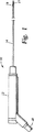
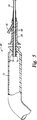
図1は、本発明に使用される形式の冷凍外科用プローブの側面図である。
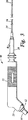
図2Aは、本発明の使い捨てシースの側面図である。
図2Bは、本発明の使い捨てシースの変形実施形態の側面図である。
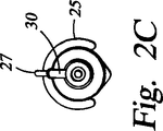
図2Cは、図2Bに示す使い捨てシースの変形実施形態の末端側端面図である。
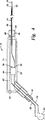
図3は、本発明に従って冷凍外科用プローブ上の定位置に配置された使い捨てシースの側面図である。
図4は、図1に示すような冷凍外科用プローブの略図である。
図5は、図2Aに示すような使い捨てシースの基端部の断面図である。
図6は、図1に示すような冷凍外科用プローブの末端側端面図である。
図7は、シュラウドを畳んだ状態の図1の使い捨てシース基端部の側面図である。
図8は、シュラウドを畳んだ状態の図7の使い捨てシース基端部の断面図である。
図9は、使い捨てシースのコネクタ本体の基端部の縦断面図である。
図10は、使い捨てシースのコネクタ本体の末端部の縦断面図である。
図11は、使い捨てシースのコネクタ本体の末端部の横断面図である。
図12Aは、冷凍外科用プローブのカニューレに取り付けられた使い捨てシースのカテーテルの横断面図である。
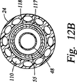
図12Bは、冷凍外科用プローブのカニューレに取り付けられていて、真空ジャケットを有する使い捨てシースのカテーテルの変形実施形態の横断面図である。
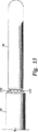
図13は、使い捨てシースのカテーテルの末端部の側面図である。
図14は、使い捨てシースのカテーテルの末端部の縦断面図である。
発明の詳細な説明
本発明は、閉ループ式混合ガス利用ジュール−トムソン型冷凍装置で動作する冷凍外科用プローブへの使い捨て可能なシースの使用に関する。かかる冷凍外科用プローブ10は、図1に示されている。プローブ10は主として、ハンドル12と、中空管状カニューレ14と、低温先端部16とから成る。ハンドル12は、効果的な封止を行いやすいよう金属製であるのがよい。ハンドルは、ハンドル12内部に真空を保持し、それにより断熱を可能にするようハンドルの筒体に真空ろう付けされたエンドキャップを有するのがよい。変形例として、ハンドル12に断熱材、例えばエーロゾルを詰め込んでもよい。冷凍装置の幾つかの構成要素、例えば熱交換器を、例えば温度センサ、ヒータ、照明用光学系、視認用光学系、レーザ光学系及び超音波交換器のような各種装置を支援する種々の補助器具と一緒にハンドル12内に収納するのがよい。ハンドル12の基端部から延びるアンビリカルコード18は、冷凍装置用の管類、電気部品の電力ケーブル、又は照明、視認及びレーザ機器を支援する光ファイバーケーブルを収容するのがよい。
冷凍装置の他の構成要素、例えば高圧ガス混合物をプローブハンドル12から低温先端部16に運ぶための高圧導管及び膨張したガス混合物を低温先端部16からプローブハンドル12に戻すための低圧導管を中空カニューレ14内に収容するのがよい。冷凍装置のさらに他の構成要素、例えばジュール−トムソン型膨張要素を低温先端部16内に収容するのがよい。通例、中空カニューレ14は、周囲組織から低温ガス混合物への熱の伝達を最少限に抑えるよう設計されている。これは、熱抵抗性材料、例えば剛性のプラスチックで作ったものであってもよく、或いは、熱伝達を阻止するよう内部又は外部に断熱材が施された金属で作ったものであってもよい。カニューレ14は、図示のように剛性の管であってもよく、或いは、用途に応じて一層可撓性があって異なる形状のものであってもよい。低温先端部16は、標的組織から膨張したガス混合物への熱伝達を最大限にするよう設計された伝熱要素である。これは、熱伝導性材料、例えば金属、好ましくは銀で作るのがよい。低温先端部16は、図示のようにカニューレ14の末端部に設けられたカップ状の要素であるのがよく、或いはこれは用途に応じて別の形状のものであってカニューレ14上のどこか別の場所に配置してもよい。低温先端部16を使い捨てシースの内側に嵌めるとサーマルグリースの流れを可能にする複数の溝17が低温先端部16に形成されている。冷凍外科用プローブ10は閉ループ式冷凍装置に用いられるので、これは汚染を防止するよう必然的に封止されることになる。この冷凍外科用プローブは、部品の交換ができるよう壊すことのできるジョイントを有するのがよいが、かかるジョイントはいずれも、通常の殺菌処置には適していない封止用部品を必然的に有することになる。
図2Aは、プローブ10の有効性を低下させないで無菌環境内でプローブ10を使用できるようにするためにプローブ10上に装着できる使い捨てで且つ殺菌可能なシース20を示している。シース20は容易に殺菌でき、しかも使い捨てできるほど安価に作れるので、プローブ10を殺菌する必要はない。使い捨てシース20は、プローブハンドル12上に嵌まるグリップ22を有し、このグリップは好ましくは、外科医にしっかりとした感触を与える波形部又は他の表面特徴を備えている。伸長自在なシュラウド23がグリップ22の基端部に取り付けられ、又は基端部上に形成されている。シュラウド23は、図2Aではアンビリカルコード18及びプローブハンドル12の基端部を覆う拡開又は伸長状態で示されている。グリップ22及びシュラウド23は、熱の不導体、例えばプラスチックで作られている。シュラウドは、プローブハンドル12及びアンビリカルコード18上に嵌まることができるよう或る程度の可撓性を有している。シース20は、末端側ヘ延びる中空管状カテーテル24を更に有している。中空カテーテル24は、冷凍外科用プローブ10のカニューレ部分14を覆うような寸法形状に設定されており、好ましくは外科環境におけるプローブ10の使用を邪魔しないようプローブカニューレ14上に締り嵌め状態になる。中空カテーテル24は、周囲組織からプローブカニューレ14への熱伝達を一段と阻止するよう熱抵抗性材料、例えばプラスチックで作られている。
熱伝導性セグメント、例えばカップ状チップ26が中空カテーテル24の末端部に取り付けられている。シースチップ26は、シースチップ26を介するプローブ低温先端部16への熱の伝達を最大限にするためにプローブ低温先端部16上にぴったりと嵌まるような寸法形状に設定されている。シースチップ26は、図示のようにカテーテル24の末端部上に設けれたカップ状の要素であってもよく、或いはプローブ低温先端部16の形状及び位置に適合するよう他の形状に作られると共に他の場所に配置された熱伝導性セグメントであってもよい。シースの熱伝導性セグメント、例えばシースチップ26を、熱を伝達しやすい材料、例えば金属で作る必要がある。シース20の構成要素は全て、封止関係をなして互いに取り付けられており、したがってシース20が無菌状態の時、このシースはプローブ10を無菌エンベロープの状態で覆い、プローブ10を外科環境で使えるのに適したものにする。冷凍外科と関連して用いられる種々の補助器具を、以下に説明するように中空カテーテル24又はシースチップ26内に設けるのがよい。これら器具としては、温度センサ、ヒータ、視認用光学系、照明用光学系、レーザ光学系及び超音波変換器が挙げられる。これら器具又はこれらの器具からの読みを表示する装置を動作させる制御装置を、外科医が観察しやすく且つ使用しやすいようプローブハンドル12内又はどこか別の場所に設けるのがよい。シースチップ26の近くに位置した器具とプローブハンドル12内又はその近くに位置した制御装置との接続は、以下に説明するように中空カテーテル24によって行うことができる。
シース20は、幾つかの機能を実行する実質的に剛性のコネクタ本体28を更に有するのがよい。コネクタ本体28は、中空カテーテル24をグリップ22に連結するための手段となる。これは、シース20をプローブ10に係止するための手段にもなることができる。さらに、コネクタ本体28は、シースチップ26の近くの補助器具をプローブハンドル12に接続するためのコネクタ、例えば電気接点又は光学部品のための取付け位置となることができる。
最後に、コネクタ本体28は、シースチップ26に隣接した領域への流体の出入れを行うのに用いることができるポート又は取付け具(又は、管継手)30、例えばルアー取付け具の取付け場所となることができる。この領域への流体の流れは、流体、例えば生理的食塩水を小さな開口部を有する体腔内に注入しなければならないような或る用途では必要となる場合がある。かかる用途の一例は、子宮内膜切除のための子宮内へのプローブカニューレ14の挿入である。チップ26の周りの領域への流体の流れ、例えばこの領域の灌注に適した生理的食塩水又は別の流体の流れは、取付け具30に取り付けられた注射器によって行うことができる。変形例として、図2B及び図2Cに示すように、曲げやすい生理的食塩水リザーバ25をグリップ22に取り付け、そして管27で取付け具30に連結するのがよい。生理的食塩水リザーバ25を握って絞ったり押すことにより、生理的食塩水を取付け具30内へ注入することができる。注入された流体は、プラグ(図示せず)をカニューレ14及びカテーテル24上に滑らせてカテーテル24と体腔の開口部とをぴったりと嵌合状態にすることにより体腔内に保持できる。同様に、バルーン(図示せず)をカテーテル24の周りに膨らませると、体腔の開口部に密着して封止することができる。チップ26の周りの領域からの流体の流れは、真空源を取付け具30に連結することによって達成できる。流体の流れは、中空カテーテル24を経てチップ領域と取付け具30との間を通過することができるが、これについては以下に説明する。
図2Aは又、シースグリップ22の末端部に形成されたフィンガストップ32及びコネクタ本体28の基端部に形成されたフィンガスライダ34を示している。以下に示すように、フィンガスライダ34をフィンガストップ32に向かって引っ張ると、コネクタ本体28をプローブハンドル2から掛け外すことができる。
図3は、プローブ10上に無菌カバーとして配置されていて、熱を標的組織からプローブ10の低温先端部16に効果的に伝達するための熱伝導性セグメントを備えた無菌シース20から成る本発明の組合せ式冷凍外科用器具40を示している。シース20のシュラウド23は、プローブハンドル12の基端部及びアンビリカルコード18上に伸長するほど可撓性であることは注目されるべきである。
図4は、本発明に組み込むことができる代表的なプローブ10の構成要素及び機能を図示するための縦断面図の形で表した冷凍外科用プローブ10の略図である。高圧ガス管36は、プローブ10内の冷凍装置構成要素への温かい高圧ガス混合物を提供し、低圧ガス管38は、プローブ10から戻る低温の低圧ガス混合物を受け取る。高圧ガス管36及び低圧ガス管38はそれぞれ、ガス圧縮機42の出口及び入口に連結されている。高圧管36は又、予冷熱交換器44を介して高圧通路に連結され、低圧管38は熱交換器44を介して低圧通路に連結されている。熱交換器44は、高圧ガスが低温先端部16のところで膨張する前に、低温低圧膨張ガス混合物との熱交換によって温かい高圧ガス混合物を予冷する。
熱交換器44の高圧出口46は、高圧導管48に連結され、この高圧導管48は中空カニューレ14を貫通して低温先端部16まで延びている。高圧導管48の末端部のところでは、低温先端部16内に或いはこの直ぐ隣にジュール−トムソン型膨張要素50が設けられている。高圧導管48を通って流れる高圧低温ガス混合物は、膨張要素50によって断熱膨張してガス混合物の温度を著しく下げる。次に、一層低温になった低圧ガス混合物を低温先端部16にあて、標的組織を熱伝導性シースチップ26を介して冷却する。分離板52が、低温先端部16の低圧領域をプローブカニューレ14から隔離している。低圧ガス混合物は、分離板52に設けられた開口部を通って戻り、プローブカニューレ14を経て熱交換器44の低圧入口54に戻る。カニューレ14を通る低圧ガス混合物の戻りは実際には、図4には示していない低圧導管を介して行うことができる。
雌型コネクタ取付け具56が、プローブ10とシース20の嵌合場所となるようプローブハンドル12の末端部に設けられている。雌型コネクタ56の外周部の周りには、内方に突出した係止又は掛止めフランジ58を設けるのがよい。シース20によって支持された補助器具と結合する1又は2以上のコネクタ要素60を雌型コネクタ56内に設けるのがよい。コネクタ要素60は、例えば温度センサ、ヒータ又は超音波変換器のような補助器具に用いられる電気接点であるのがよい。同様に、コネクタ要素60は、例えば視認用光学系、照明用光学系又はレーザ光学系のような補助器具に用いられる光学部品であるのがよい。コネクタ要素60は、器具用導体62によりディスプレイ又は制御装置64に接続されている。器具用導体62は適宜、電気導体又は光ファイバ束であるのがよい。分かりやすくするために、コネクタ要素60、導体62及びディスプレイ又は制御装置64が一組だけ示されているが、複数のかかる装置を任意の冷凍外科用器具40内に用いてもよいことは理解されるべきである。さらに、ディスプレイ又は制御装置64を例えばビデオ光学ビューイングシステムに適したものであるように器具40から遠隔地に設置してもよいことは理解されるべきである。位置合せ用リブ66を、プローブハンドル12の周囲に形成してプローブハンドル12とシースグリップ22の位置合せに役立つようにするのがよい。
図5は、プローブカニューレ14を通すことができるようにする長手方向ボア68がコネクタ本体28を貫通して設けられていることを示している。取付け具30は、ボア68内に延びる中空カテーテル24の外部に流体の流れを提供するようボア68と流体連通している。雄型コネクタ取付け具70が、プローブハンドル12の末端部の雌型コネクタ取付け具56と嵌合するようコネクタ本体28の基端部に設けられている。掛外し自在なラッチ72が、係止用フランジ58に係合するよう雄型コネクタ取付け具70に設けられている。また、コネクタ要素60をプローブハンドル12の雌型コネクタ取付け具56内に嵌めるために雄型コネクタ取付け具70には、1又は2以上のコネクタ要素74が設けられている。コネクタ要素74と補助器具との連結状態及び取付け具70から中空カテーテル24への流体流路の接続状態が、次の図に一層よく示されている。図6は、プローブハンドル12の端面図であり、雌型コネクタ取付け具56の内部を示している。複数のコネクタ要素60が、雌型取付け具56内に円をなす状態で示されている。
図7は、シュラウド23が収納又は収縮状態にあるシース20を示している。シースは、冷凍外科用プローブ10上に配置されるまで、通常この状態で輸送されたり保管される。シュラウド23をプローブハンドル12及びアンビリカルコード18上に引っ張りやすいようにするためにタブ78がシュラウド23の基端部に設けられている。図8は、シース20の一実施形態の細部を示す断面図である。プローブハンドル12の外部に設けられた位置合せ用リブ66と嵌合する位置合せ用溝76がシースグリップ22の内ボア内に示されている。コネクタ本体28を多部品組立体として構成するのがよいことが分かる。
図9は、コネクタ本体28の一実施形態の細部及びこれとシースグリップ22との接続状態を示している。コネクタ本体28は本質的に、末端セクション80、中間セクション82及び基端セクション84を有している。末端セクション80は、フィンガスライダ34を有し、末端セクション80の末端部は、中空カテーテル24に取り付けられている。中間セクション82は、末端セクション80の基端部内に設けられ、この中間セクションは末端セクション80を器具用コネクタ74に接続すると共に掛外し自在なラッチ72に接続する手段となる。中間セクション82は、ラッチ72に螺合した図示のようなバレル92からなるのがよい。コレット86が、バレル92とラッチ72との間に嵌め込まれている。コレット86は、スリーブ90に取り付けられ、このスリーブはコネクタ取付け具96に取り付けられている。器具用導体94は器具用コネクタ74に接続されている。器具用導体94は、長手方向ボア68を通って、又はこれと並んでカテーテル24まで延びている。
図10は、コネクタ本体28の末端セクション80の末端部の一実施形態の細部を示している。長手方向ボア68の末端部は、流体ボア100で終端し、この流体ボアは取付け具30の内ボア98と流体連通している。中空カテーテル24の基端部は、流体ボア100内に延び、流体ボア100の直径はカテーテル24の外径よりも大きい。これにより、流体ボア100内においてカテーテル24の回りには流体の流れ空間が生じる。流体ボア100の基端部102を長手方向ボア68内に設けられた肩で終端させるのがよい。逆に、流体ボア100の基端部102をエポキシシールで終端させるのがよい。プローブカニューレ14は、長手方向ボア68にぴったりと嵌まり込むことができる。コネクタ本体28の末端部を歪取りカラー106に嵌合させてカテーテル24をコネクタ本体28に締結するのがよい。カラー106内のスペース108をエポキシで満たして流体ボア100の末端部を成端加工するのがよい。
図11は、コネクタ本体28の末端部及び中空カテーテル24の基端部の断面図を示している。この図では、カテーテル24は多内腔カテーテルである。複数の内腔110が、カテーテル24の壁を長手方向に貫通して延びている。内腔110の中には、符号112で示すように流体の流れを導くのに用いられるものもあれば、符号114で示すように補助器具の信号を伝えるのに用いられるものもある。流体ボア100内でのみ、流体用内腔112はカテーテル24の外部に開口しており、カテーテル24の長さの残部に沿う流体用内腔112は外部には開口していない。器具用内腔114は、カテーテル24の長さ全体にわたって外部に対して閉じられている。流体用内腔112が流体ボア100内で外部に開口しているので、流体は取付け具30からカテーテル24の壁内に或いはカテーテル24の壁から取付け具30に流れることができる。中央ボア116が、プローブカニューレ14を受け入れるようカテーテル24を貫通している。
図12Aは、コネクタ本体24の前方に位置したカテーテル24及びプローブカニューレ14の横断面図を示している。カニューレ14は組をなす3本の同軸ステンレス鋼管48,55,57を有し、外側の管57はカテーテル24内に実質的にぴったりと嵌まっている。外側管57と低圧導管55との間には真空又は断熱空間118が形成されていることが分かる。低圧導管55は熱交換器44の低圧入口54に通じている。高圧導管48は低圧導管55内に位置している。
図12Bは、コネクタ本体28の前方に位置したカテーテル24及びプローブカニューレ14の変形実施形態の横断面図を示している。カニューレ14は、組をなす2本の同軸ステンレス鋼管48,55を有し、外側の管55は、カテーテル24内の内側の管117内に実質的にぴったりと嵌まっている。カテーテル24内では内側の管117とカテーテル24との間に真空ジャケット又は断熱空間118が形成されていることが分かる。ここでも上述した構成と同様に、低圧導管55は熱交換器44の低圧入口54に通じている。高圧導管48は低圧導管55内に位置している。
図13は、中空カテーテル24の末端部及びシースチップ26の側面図を示している。内腔110内の複数のポート120が、カテーテル24の末端部に形成されている。ポート120のうち幾つかは、シースチップ26に隣接した領域に流体を出入れするためのものである。別のポート120は、視認、照明又はレーザ装置を支援するための光学部品用に用いられる。さらに別のポート120は、シースチップ26内の温度センサ、ヒータ又は超音波変換器への電気接続のための接続端子として用いることができる。
図14は、カテーテル24の末端部及びシースチップ26の縦断面図を示している。補助器具用導体94は、内腔114を通ってカテーテル24の末端部に至り、この箇所においてポート120内の光学部品又はシースチップ26内の補助器具126につながっている。補助器具126は、温度センサ、ヒータ、組織インピーダンス測定部品、又は温度検出機能、インピーダンス測定機能及び加熱機能のうち2以上を果たす統合型部品であるのがよい。例えば、補助器具126は、ポリイミド樹脂フィルムから成る非常に薄い(0.003インチ(0.0762mm))シート相互間に積層された箔で構成されているヒータと抵抗温度検知器を一つにしたもの(ヒータと抵抗温度検知器の兼用装置)であってもよい。さらに、補助器具は超音波変換器であってもよい。シースチップ26内に設けられた補助器具126は、内側の熱伝導性層122と外側の熱伝導性層124との間にサンドイッチされたものであるのがよい。内側熱伝導性層122を銅で作るのがよく、外側熱伝導性層124をステンレス鋼で作るのがよい。所望ならば、エポキシを器具126と熱伝導性層122,124との間に注入するのがよい。外側の層124に設けられたエポキシ放出穴128がこの目的のために設けられている。もし断熱層を器具126と内側層122及び外側層124との間に設ける場合、断熱層はこれを通る熱伝達が可能なほど薄くなければならない。熱伝導性グリース130をシースチップ26内に設けてプローブチップ16とシースチップ26との間の熱接触を極力高めるのがよい。
詳細に図示説明した本発明は、上述の目的を完全に達成できると共に上述の利点を完全にもたらすことができるが、本願の開示内容は、本発明の現時点において好ましい実施形態の例示にすぎず、本発明の範囲に関し、特許請求の範囲に記載された限定以外に何ら限定がなされるものではない。Background of the Invention
The present invention relates to the field of cryosurgical probes used to freeze and thereby destroy biological tissue. More particularly, the present invention is useful in the field of cryosurgical probes cooled by a closed loop Joule-Thomson refrigeration system.
The Joule-Thomson refrigeration system operates by expanding high pressure gas in an expansion element that incorporates a sort of flow restriction. The flow restriction is a small orifice, narrow capillary, or some other narrow passage. Typically, a refrigeration system includes a high pressure gas source, a heat exchanger, an expansion element, a heat or heat transfer element, and various tubes or conduits that direct gas from one component to another. Have. The high pressure gas passes through the heat exchanger to lower the gas temperature somewhat, and then the gas temperature is further reduced in the expansion element. This is because adiabatic expansion occurs. The expanded and cooled gas is applied to a heat transfer element, where the gas absorbs heat transferred from the surrounding environment. The operation of the Joule-Thomson refrigeration system can be severely adversely affected by contaminants in the gas, such as water, oil or particles. Such contaminants tend to clog the flow restrictor in the expansion element. This is because the flow restriction is generally very small.
Water and oil are particularly harmful contaminants because they collect selectively at the flow restriction where the majority of the cooling action occurs. As the gas expands and cools, the temperature of the entrained water and oil also decreases, so that the water and oil freeze or solidify. This solidification phenomenon occurs just at the flow restrictor. The reason is that this is where cooling actually takes place. Water and oil are often found in the ambient air, at least in trace amounts, so they can enter the refrigeration system if the refrigeration unit joints are disconnected or refrigeration unit parts are replaced. is there.
Most Joule-Thompson type devices are of the open loop type, meaning that the gas is discharged into the atmosphere after expansion and heat absorption. The high pressure gas source of such devices is usually a high pressure gas cylinder. If you continue to use, the amount of gas in the cylinder will decrease. Such an open loop device may contain a certain amount of contaminants. This is because, during use, contaminants are exhausted from the device with the gas into the surrounding environment. If contaminants enter the device during component replacement, or if the device coupling breaks for another reason, the contaminants will flow out primarily when the gas is subsequently exhausted.
However, it is possible to use a closed loop Joule-Thomson type device, which means that the gas is repressurized and circulated after expansion. The low pressure gas expands in the expansion element, hits the heat transfer element, and after absorbing heat, is returned to a compressor that can be used to repressurize the gas. The repressurized gas is then circulated back into the heat exchanger and expansion element. No gas is exhausted from the device. Thus, contaminants entering the device collect within the device and accumulate over a period of time. The level of contamination may eventually increase to a level where the expansion element becomes clogged by water and oil solidification. Ultra-compact as disclosed in US patent application Ser. No. 08 / 542,123 filed Oct. 12, 1995 and US application Ser. No. 08 / 698,044 filed Aug. 15, 1996. A method and apparatus for operating a mixed gas Joule-Thompson type refrigeration apparatus have been developed. It should be noted that the contents of such US patent applications are cited as forming part of this specification. When such a mixed gas is used particularly in a small-sized or ultra-small refrigeration apparatus, introduction of air into the apparatus may change the mixing ratio of the gas mixture, and the cooling performance of the gas mixture may be significantly impaired.
For these reasons, closed loop Joule-Thompson devices are often permanently sealed to prevent the introduction of contaminants. Part replacement or disconnection of other device fittings is not possible with a permanently sealed device. Some devices use self-sealing joints that automatically seal the device when disconnected. This automatic sealing scheme limits the amount of leakage and contamination, but some contamination still occurs. Typically, the fittings used in closed loop devices are threaded fittings or pipe fittings that are not designed to allow repeated disconnection.
The contamination problem becomes even more troublesome with closed loop mixed gas based Joule-Thomson refrigeration devices used in surgical instruments such as cryosurgical probes. Such instruments typically have a compressor coupled to the probe, which essentially consists of a handle, a cannula and a cold tip. The heat exchanger is typically provided in the handle and the expansion element is typically provided in the cold tip. The probe cannula or cold tip must be compatible with various shapes, such as flat, cylindrical or thin blade shapes, to perform various functions. Furthermore, the cryogenic tip must be sterilizable for surgery to allow repeated use of the refrigeration device for different patients.
Known cryosurgical probes are open loop devices for this reason. In an open loop device, the cannula or cold tip can be removed and sterilized or discarded. The entry of contaminants into the refrigeration system during removal and replacement of the cannula or cold tip is not a major problem with open loop systems. This is because contaminants can be flushed out of the device at the time of gas discharge. Open loop devices are wasteful and expensive to operate because they require continuous gas exchange. Also, exhausting gas to the surrounding environment is not always environmentally safe. Closed loop devices are more economical and environmentally safe. If a known closed loop device is used for surgical applications, removal and replacement of the cannula or cold tip for sterilization can cause contaminants to enter the device and eventually clog the expansion element. A closed loop surgical device should theoretically have a self-sealing joint, but contaminants will still accumulate over a period of time. Furthermore, the self-sealing joint has an O-ring and precision parts. Sterilization of the cannula or cold tip inevitably exposes the O-ring and precision parts to high temperature and harsh chemicals, ultimately degrading the sealing performance of the joint.
Using a disposable replacement cannula or cold tip does not solve this dilemma. First, even if the replaceable part is discarded and replaced with a sterile new one, it must be repeatedly cut off, and the final result is the accumulation of contaminants. Secondly, most disposable parts are made of plastic for economic reasons. Plastics generally contain a small amount of water. If the plastic parts are exposed to gas in the refrigeration unit, the water may eventually leach out of the plastic and contaminate the gas in the unit. Third, the use of self-sealing joints typically increases the size and weight of the device and significantly increases costs, and the use of self-sealing joints is undesirable for disposable instruments. Fourth, each time the disposable element, such as a cannula or cold tip, is discarded, the refrigerant gas contained within the disposable element is lost. Thereby, it is necessary to exchange gas in order to avoid deterioration of the cooling performance of the apparatus. The discharge of gas from disposable parts or the use of replacement parts pre-filled with gas will significantly increase the structural complexity and cost of the device.
Further, a typical cryosurgical probe includes one or more auxiliary instruments provided near the low temperature tip and used in cooperation with the low temperature tip, such as a temperature sensor, a heater, an ultrasonic transducer, and an optical component. And have fluid ports for irrigation and aspiration. When reusable probes are used, their performance may be degraded by repeated sterilization of these auxiliary devices. The ideal way is to incorporate these auxiliary devices into the disposable element.
Finally, it is desirable to insulate the cryosurgical probe shaft to prevent undesired tissue freezing along the probe when the cryosurgical probe is inserted into a body cavity or organ. One effective means of thermal insulation is to provide a vacuum space along the probe shaft. However, the level of vacuum maintained in such a space may decrease over time due to outgassing of metal, plastic and brass fittings. This outgassing increases during the sterilization procedure where heat is applied to the probe. Therefore, it is desirable to incorporate a vacuum insulation space into the disposable element. The disposable element can only be sterilized once and then the disposable element can be economically discarded, and the degree of vacuum level reduction is minimized.
Summary of the Invention
The present invention relates to a disposable sterilized sheath for use in a closed loop Joule-Thomson cryosurgical probe and a combination of a disposable sheath and a probe. The sheath is so flexible that it can be slid onto the probe so that the probe is isolated from the surrounding environment and can be used for surgical applications. The sheath has a grip that fits snugly on the handle of the cryosurgical probe and an extendable shroud attached to the proximal end of the grip. The shroud can extend longitudinally to cover the refrigerant tube and instrument cable attached to the handle, thereby providing a sterile barrier for these components.
The sheath also has a hollow multi-lumen catheter sized and shaped to fit snugly into the cannula of the cryosurgical probe. Because the catheter is not thermally conductive, it prevents the transfer of heat from the environment to the gas mixture and prevents tissue freezing in undesirable locations. By providing thermal insulation means, such as a vacuum space, along the side of the catheter, the thermal conductivity of the catheter can be reduced. A thermally conductive segment is attached to the distal end of the multi-lumen catheter in the form of a metal cap or tip. The metal tip may be round, flat, pointed, or any other shape suitable for the cryosurgery performed. The thermally conductive cap or tip fits snugly into the cold tip of the probe, which effectively transfers heat from the target tissue to the cold tip, which cools the heat to the expanded gas mixture. introduce. Various forms of auxiliary devices such as temperature sensors, heaters, ultrasonic exchangers, or optical components of visual, illumination or laser devices may be attached to the catheter or conductive cap. The connection between the instrument and the probe located near the distal end of the catheter is made through a plurality of lumens extending longitudinally through the catheter wall. Fluid passages may be provided in the catheter and may be connected to a fluid source connected to or attached to the sheath, such as a saline reservoir attached to the grip of the sheath.
The novel features of the invention, as well as the content of the invention itself, are best understood with reference to the accompanying drawings, in conjunction with the following description. In addition, in the figure, the same code | symbol is attached | subjected to the same part.
[Brief description of the drawings]
FIG. 1 is a side view of a cryosurgical probe of the type used in the present invention.
FIG. 2A is a side view of the disposable sheath of the present invention.
FIG. 2B is a side view of an alternative embodiment of the disposable sheath of the present invention.
2C is a distal end view of an alternative embodiment of the disposable sheath shown in FIG. 2B.
FIG. 3 is a side view of a disposable sheath placed in place on a cryosurgical probe in accordance with the present invention.
FIG. 4 is a schematic diagram of a cryosurgical probe as shown in FIG.
FIG. 5 is a cross-sectional view of the proximal end of the disposable sheath as shown in FIG. 2A.
FIG. 6 is a distal end view of the cryosurgical probe as shown in FIG.
7 is a side view of the proximal end of the disposable sheath of FIG. 1 with the shroud folded.
8 is a cross-sectional view of the disposable sheath proximal end of FIG. 7 with the shroud folded.
FIG. 9 is a longitudinal sectional view of the proximal end portion of the connector main body of the disposable sheath.
FIG. 10 is a longitudinal sectional view of a distal end portion of the connector main body of the disposable sheath.
FIG. 11 is a cross-sectional view of the distal end of the connector body of the disposable sheath.
FIG. 12A is a cross-sectional view of a disposable sheath catheter attached to the cannula of a cryosurgical probe.
FIG. 12B is a cross-sectional view of an alternative embodiment of a disposable sheath catheter attached to a cannula of a cryosurgical probe and having a vacuum jacket.
FIG. 13 is a side view of the distal end of a disposable sheath catheter.
FIG. 14 is a longitudinal sectional view of the distal end of a disposable sheath catheter.
Detailed Description of the Invention
The present invention relates to the use of a disposable sheath for a cryosurgical probe operating on a closed loop mixed gas based Joule-Thomson refrigeration system. Such a
The hollow cannula includes other components of the refrigeration apparatus, such as a high pressure conduit for carrying the high pressure gas mixture from the probe handle 12 to the
FIG. 2A shows a disposable and
A thermally conductive segment, such as a cup-shaped
The
Finally, the
FIG. 2A also shows a
FIG. 3 illustrates the present invention comprising a
FIG. 4 is a schematic illustration of a
The
A female connector fitting 56 is provided at the distal end of the probe handle 12 so as to be a fitting place between the
FIG. 5 shows that a
FIG. 7 shows the
FIG. 9 shows details of an embodiment of the connector
FIG. 10 shows details of one embodiment of the distal end of the
FIG. 11 shows a cross-sectional view of the distal end of the
FIG. 12A shows a cross-sectional view of the
FIG. 12B shows a cross-sectional view of an alternative embodiment of the
FIG. 13 shows a side view of the distal end of the
FIG. 14 shows a longitudinal sectional view of the distal end portion of the
Although the invention shown and described in detail may fully achieve the above objectives and provide the above advantages, the disclosure herein is merely illustrative of the presently preferred embodiments of the invention, There is no limitation on the scope of the present invention other than the limitations described in the claims.
Claims (23)
冷凍外科用プローブのハンドル部分上に着脱自在に装着可能な中空グリップと、
前記中空グリップに取り付けられたカテーテルであって、冷凍外科用プローブのカニューレ部分上に着脱自在に配置可能なカテーテルと、
前記カテーテルに取り付けられた熱伝導性セグメントであって、冷凍外科用プローブの伝熱部分と熱接触状態で、該伝熱部分上に着脱自在に配置可能な熱伝導性セグメントと、
を有することを特徴とするシース。A sheath for use as a removable aseptic cover for a cryosurgical probe, the sheath comprising:
A hollow grip that can be detachably mounted on the handle portion of the cryosurgical probe;
A catheter attached to the hollow grip, the catheter being removably disposed on a cannula portion of a cryosurgical probe;
A thermally conductive segment attached to the catheter, wherein the thermally conductive segment is detachably disposed on the heat transfer portion in thermal contact with the heat transfer portion of the cryosurgical probe;
A sheath characterized by comprising:
冷凍外科用プローブカバーとして使用するためのシースと、
前記シース上の中空グリップと、
前記シース上のカテーテルであって、その近位端が前記中空グリップに取り付けられたカテーテルと、
前記シースカテーテルに取り付けられた熱伝導性セグメントと、
前記シースカテーテルの前記熱伝導性セグメント内の熱伝導性媒体と、
を有することを特徴とする装置。A device for use in performing cryosurgery,
A sheath for use as a cryosurgical probe cover;
A hollow grip on the sheath;
A catheter on the sheath, the proximal end of which is attached to the hollow grip;
A thermally conductive segment attached to the sheath catheter;
A thermally conductive medium in the thermally conductive segment of the sheath catheter;
A device characterized by comprising:
さらに前記コネクタ本体を通る管状流路を有する、
請求項2に記載の装置。A connector body attached to the hollow grip for attaching the sheath to a cryosurgical probe; the sheath catheter is attached to the connector body;
Furthermore, it has a tubular flow path through the connector body,
The apparatus of claim 2.
前記補助器具に連結されたコネクタ要素であって、前記補助器具の前記冷凍外科用プローブへの連結のために、前記コネクタ本体に取り付けられるコネクタ要素と、
をさらに有する請求項6に記載の装置。An auxiliary instrument attached to the sheath catheter adjacent to the thermally conductive segment, the auxiliary instrument performing an auxiliary function during cryosurgery;
A connector element coupled to the auxiliary instrument, the connector element being attached to the connector body for coupling the auxiliary instrument to the cryosurgical probe;
The apparatus of claim 6 further comprising:
前記コネクタ要素は、前記電気ヒータを温度制御装置に接続するようにした電気接点を有する、
請求項8に記載の装置。The auxiliary device has an electric heater,
The connector element has electrical contacts adapted to connect the electric heater to a temperature control device;
The apparatus according to claim 8.
前記コネクタ要素は、前記温度センサを温度読取り装置に接続するようにした電気接点を有する、
請求項8に記載の装置。The auxiliary device has a temperature sensor;
The connector element has electrical contacts adapted to connect the temperature sensor to a temperature reading device;
The apparatus according to claim 8.
前記コネクタ要素は、前記光学部品を光伝送装置に接続するようにした光ファイバを有する、
請求項8に記載の装置。The auxiliary device has an optical component,
The connector element includes an optical fiber adapted to connect the optical component to an optical transmission device;
The apparatus according to claim 8.
前記コネクタ要素は、前記インピーダンス測定部品をインピーダンス読取り装置に接続するようにした電気接点を有する、
請求項8に記載の装置。The auxiliary instrument has an impedance measurement component,
The connector element has electrical contacts adapted to connect the impedance measuring component to an impedance reader;
The apparatus according to claim 8.
前記カテーテルを貫通して形成された流体流路であって、前記第1の流体ポートと流通する流体流れ通路と、
前記カテーテル内に形成された第2の流体ポートであって、前記流体流れ通路と流通する第2の流体ポートとを、
有する請求項6に記載の装置。A first fluid port formed in the connector body;
A fluid flow path formed through the catheter, wherein the fluid flow path is in communication with the first fluid port;
A second fluid port formed in the catheter, the second fluid port communicating with the fluid flow passage;
The apparatus of claim 6.
前記第2の流体ポートは、流体出口を有し、
前記装置は、前記カテーテルに灌注用流体を供給するために、前記第1の流体ポートに接続された流体源をさらに有する、
請求項13に記載の装置。The first fluid port has a fluid inlet;
The second fluid port has a fluid outlet;
The apparatus further comprises a fluid source connected to the first fluid port for supplying irrigation fluid to the catheter.
The apparatus of claim 13.
前記第2の流体ポートは、流体入口を有し、
前記装置は、物質を前記カテーテル経由して吸引するために、前記第1の流体ポートに接続された真空源をさらに有する、
請求項13に記載の装置。The first fluid port has a fluid outlet;
The second fluid port has a fluid inlet;
The apparatus further comprises a vacuum source connected to the first fluid port for aspirating material through the catheter.
The apparatus of claim 13.
器具用導体を受け入れるように前記カテーテル内の少なくとも第2の内腔とを有する請求項17に記載の装置。A first lumen provided in the catheter and adapted to receive a cannula portion of a cryosurgical probe;
18. The device of claim 17, having at least a second lumen in the catheter to receive an instrument conductor.
流路用にした前記カテーテル内の少なくとも第2の内腔とを有する請求項17に記載の装置。A first lumen in the catheter adapted to receive a cannula portion of a cryosurgical probe;
18. The device of claim 17, having at least a second lumen in the catheter for a flow path.
前記中空シースグリップによって覆われた、前記プローブ上のハンドルと、
前記シースカテーテルによって覆われた、前記プローブ上のカニューレと、
前記シースカテーテルの前記熱伝導性セグメントによって覆われた、前記プローブカニューレ上の伝熱要素と、
前記伝熱要素内に所望冷凍温度で冷媒を提供する冷媒装置と、を有し、
前記熱伝導性媒体は、前記プローブの前記伝熱要素と前記シースカテーテルの前記熱伝導セグメントとの間に設置される、
請求項2に記載の装置。A cryosurgical probe covered by the sheath;
A handle on the probe covered by the hollow sheath grip;
A cannula on the probe covered by the sheath catheter;
A heat transfer element on the probe cannula covered by the thermally conductive segment of the sheath catheter;
A refrigerant device providing refrigerant at a desired refrigeration temperature in the heat transfer element,
The thermally conductive medium is disposed between the heat transfer element of the probe and the heat conductive segment of the sheath catheter;
The apparatus of claim 2.
Applications Claiming Priority (3)
| Application Number | Priority Date | Filing Date | Title |
|---|---|---|---|
| US08/774,148 US5910104A (en) | 1996-12-26 | 1996-12-26 | Cryosurgical probe with disposable sheath |
| US08/774,148 | 1996-12-26 | ||
| PCT/US1997/024274 WO1998029029A1 (en) | 1996-12-26 | 1997-12-19 | Cryosurgical probe with disposable sheath |
Publications (3)
| Publication Number | Publication Date |
|---|---|
| JP2001507604A JP2001507604A (en) | 2001-06-12 |
| JP2001507604A5 JP2001507604A5 (en) | 2005-08-11 |
| JP4044147B2 true JP4044147B2 (en) | 2008-02-06 |
Family
ID=25100383
Family Applications (1)
| Application Number | Title | Priority Date | Filing Date |
|---|---|---|---|
| JP53035198A Expired - Fee Related JP4044147B2 (en) | 1996-12-26 | 1997-12-19 | Cryosurgical probe with disposable sheath |
Country Status (7)
| Country | Link |
|---|---|
| US (5) | US5910104A (en) |
| EP (2) | EP0981292B1 (en) |
| JP (1) | JP4044147B2 (en) |
| AU (1) | AU722318B2 (en) |
| CA (1) | CA2276137C (en) |
| DE (2) | DE69730050T2 (en) |
| WO (1) | WO1998029029A1 (en) |
Families Citing this family (281)
| Publication number | Priority date | Publication date | Assignee | Title |
|---|---|---|---|---|
| US6203481B1 (en) * | 1994-07-22 | 2001-03-20 | Ranpak Corp. | Cushioning conversion machine |
| US6524230B1 (en) * | 1994-07-22 | 2003-02-25 | Ranpak Corp. | Packing material product and method and apparatus for making, monitoring and controlling the same |
| US6464697B1 (en) * | 1998-02-19 | 2002-10-15 | Curon Medical, Inc. | Stomach and adjoining tissue regions in the esophagus |
| US6270494B1 (en) * | 1996-12-26 | 2001-08-07 | Cryogen, Inc. | Stretchable cryoprobe sheath |
| US5910104A (en) * | 1996-12-26 | 1999-06-08 | Cryogen, Inc. | Cryosurgical probe with disposable sheath |
| US7220257B1 (en) | 2000-07-25 | 2007-05-22 | Scimed Life Systems, Inc. | Cryotreatment device and method |
| US7255693B1 (en) * | 1997-05-23 | 2007-08-14 | Csa Medical, Inc. | Heated catheter used in cryotherapy |
| EP1014873A4 (en) * | 1997-09-22 | 2003-07-09 | Ethicon Inc | Cryosurgical system and method |
| US20080027328A1 (en) * | 1997-12-29 | 2008-01-31 | Julia Therapeutics, Llc | Multi-focal treatment of skin with acoustic energy |
| US20060184071A1 (en) * | 1997-12-29 | 2006-08-17 | Julia Therapeutics, Llc | Treatment of skin with acoustic energy |
| US7371254B2 (en) | 1998-01-23 | 2008-05-13 | Innercool Therapies, Inc. | Medical procedure |
| US6585752B2 (en) | 1998-06-23 | 2003-07-01 | Innercool Therapies, Inc. | Fever regulation method and apparatus |
| US6379378B1 (en) * | 2000-03-03 | 2002-04-30 | Innercool Therapies, Inc. | Lumen design for catheter |
| US6231595B1 (en) * | 1998-03-31 | 2001-05-15 | Innercool Therapies, Inc. | Circulating fluid hypothermia method and apparatus |
| US6312452B1 (en) | 1998-01-23 | 2001-11-06 | Innercool Therapies, Inc. | Selective organ cooling catheter with guidewire apparatus and temperature-monitoring device |
| US6464716B1 (en) | 1998-01-23 | 2002-10-15 | Innercool Therapies, Inc. | Selective organ cooling apparatus and method |
| US6096068A (en) | 1998-01-23 | 2000-08-01 | Innercool Therapies, Inc. | Selective organ cooling catheter and method of using the same |
| US6261312B1 (en) | 1998-06-23 | 2001-07-17 | Innercool Therapies, Inc. | Inflatable catheter for selective organ heating and cooling and method of using the same |
| US6491039B1 (en) | 1998-01-23 | 2002-12-10 | Innercool Therapies, Inc. | Medical procedure |
| US6471717B1 (en) * | 1998-03-24 | 2002-10-29 | Innercool Therapies, Inc. | Selective organ cooling apparatus and method |
| US6325818B1 (en) | 1999-10-07 | 2001-12-04 | Innercool Therapies, Inc. | Inflatable cooling apparatus for selective organ hypothermia |
| US6387095B1 (en) | 1998-02-09 | 2002-05-14 | Loren R. Kennett | Surgical device comprising a radially expandable non-conductive sheath |
| US6551349B2 (en) | 1998-03-24 | 2003-04-22 | Innercool Therapies, Inc. | Selective organ cooling apparatus |
| US7001378B2 (en) * | 1998-03-31 | 2006-02-21 | Innercool Therapies, Inc. | Method and device for performing cooling or cryo-therapies, for, e.g., angioplasty with reduced restenosis or pulmonary vein cell necrosis to inhibit atrial fibrillation employing tissue protection |
| US6905494B2 (en) * | 1998-03-31 | 2005-06-14 | Innercool Therapies, Inc. | Method and device for performing cooling- or cryo-therapies for, e.g., angioplasty with reduced restenosis or pulmonary vein cell necrosis to inhibit atrial fibrillation employing tissue protection |
| US6602276B2 (en) | 1998-03-31 | 2003-08-05 | Innercool Therapies, Inc. | Method and device for performing cooling- or cryo-therapies for, e.g., angioplasty with reduced restenosis or pulmonary vein cell necrosis to inhibit atrial fibrillation |
| US7291144B2 (en) | 1998-03-31 | 2007-11-06 | Innercool Therapies, Inc. | Method and device for performing cooling- or cryo-therapies for, e.g., angioplasty with reduced restenosis or pulmonary vein cell necrosis to inhibit atrial fibrillation |
| US6685732B2 (en) * | 1998-03-31 | 2004-02-03 | Innercool Therapies, Inc. | Method and device for performing cooling- or cryo-therapies for, e.g., angioplasty with reduced restenosis or pulmonary vein cell necrosis to inhibit atrial fibrillation employing microporous balloon |
| US6338727B1 (en) | 1998-08-13 | 2002-01-15 | Alsius Corporation | Indwelling heat exchange catheter and method of using same |
| US6241722B1 (en) | 1998-06-17 | 2001-06-05 | Cryogen, Inc. | Cryogenic device, system and method of using same |
| US6202421B1 (en) * | 1998-10-06 | 2001-03-20 | American Superconductor Corporation | Detachable cryogenic refrigerator expander |
| US20050228367A1 (en) * | 1999-01-25 | 2005-10-13 | Marwan Abboud | Leak detection system for catheter based medical device |
| US6569158B1 (en) | 1999-01-25 | 2003-05-27 | Cryocath Technologies, Inc. | Leak detection system |
| US6592577B2 (en) * | 1999-01-25 | 2003-07-15 | Cryocath Technologies Inc. | Cooling system |
| US20030028182A1 (en) * | 1999-04-21 | 2003-02-06 | Cryocath Technologies Inc. | Cryoablation catheter handle |
| US7905879B2 (en) * | 1999-04-21 | 2011-03-15 | Medtronic Cryocath Lp | Cryoablation catheter handle |
| US6440126B1 (en) * | 1999-04-21 | 2002-08-27 | Cryocath Technologies | Cryoblation catheter handle |
| US7018365B2 (en) | 1999-05-21 | 2006-03-28 | Micro Therapeutics, Inc. | Threaded syringe with quick stop |
| US7363071B2 (en) | 1999-05-26 | 2008-04-22 | Endocare, Inc. | Computer guided ablation of tissue using integrated ablative/temperature sensing devices |
| US6306132B1 (en) | 1999-06-17 | 2001-10-23 | Vivant Medical | Modular biopsy and microwave ablation needle delivery apparatus adapted to in situ assembly and method of use |
| US7004936B2 (en) | 2000-08-09 | 2006-02-28 | Cryocor, Inc. | Refrigeration source for a cryoablation catheter |
| US6471694B1 (en) | 2000-08-09 | 2002-10-29 | Cryogen, Inc. | Control system for cryosurgery |
| US6193683B1 (en) * | 1999-07-28 | 2001-02-27 | Allergan | Closed loop temperature controlled phacoemulsification system to prevent corneal burns |
| GB9920112D0 (en) * | 1999-08-26 | 1999-10-27 | Aortech Int Plc | Improvements relating to catheters (I) |
| US20060095032A1 (en) * | 1999-11-16 | 2006-05-04 | Jerome Jackson | Methods and systems for determining physiologic characteristics for treatment of the esophagus |
| WO2001035846A1 (en) * | 1999-11-16 | 2001-05-25 | Ganz Robert A | System and method of treating abnormal tissue in the human esophagus |
| US20040215235A1 (en) | 1999-11-16 | 2004-10-28 | Barrx, Inc. | Methods and systems for determining physiologic characteristics for treatment of the esophagus |
| US20040220559A1 (en) * | 2000-03-01 | 2004-11-04 | Kramer Hans W. | Preparation of working fluid for use in cryotherapies |
| US6719723B2 (en) | 2000-12-06 | 2004-04-13 | Innercool Therapies, Inc. | Multipurpose catheter assembly |
| US6450987B1 (en) | 2001-02-01 | 2002-09-17 | Innercool Therapies, Inc. | Collapsible guidewire lumen |
| US6726709B1 (en) * | 2001-04-30 | 2004-04-27 | Medcool, Inc. | Method and device for reducing death and morbidity from stroke |
| US6430956B1 (en) | 2001-05-15 | 2002-08-13 | Cimex Biotech Lc | Hand-held, heat sink cryoprobe, system for heat extraction thereof, and method therefore |
| US20080051776A1 (en) * | 2001-05-21 | 2008-02-28 | Galil Medical Ltd. | Thin uninsulated cryoprobe and insulating probe introducer |
| US7094234B1 (en) | 2001-08-27 | 2006-08-22 | Medcool, Inc. | Interstitial brain cooling probe and sheath apparatus |
| JP2005503227A (en) * | 2001-09-27 | 2005-02-03 | ガリル メディカル リミテッド | Apparatus and method for cryosurgical treatment of breast tumors |
| EP1429820A4 (en) * | 2001-09-27 | 2007-11-14 | Galil Medical Ltd | Cryoplasty apparatus and method |
| US7144248B2 (en) * | 2001-10-18 | 2006-12-05 | Irwin Dean S | Device for oral UV photo-therapy |
| US6878147B2 (en) | 2001-11-02 | 2005-04-12 | Vivant Medical, Inc. | High-strength microwave antenna assemblies |
| US7128739B2 (en) | 2001-11-02 | 2006-10-31 | Vivant Medical, Inc. | High-strength microwave antenna assemblies and methods of use |
| US6878204B1 (en) * | 2001-11-14 | 2005-04-12 | Ams Research Corporation | Methods and apparatus for applying a thermal conductive medium |
| DE60213457T2 (en) * | 2001-12-03 | 2007-10-18 | Ekos Corp., Bothell | ULTRASONIC CATHETER FOR SMALL VESSELS |
| US6709431B2 (en) | 2001-12-18 | 2004-03-23 | Scimed Life Systems, Inc. | Cryo-temperature monitoring |
| EP1474059A4 (en) * | 2002-01-04 | 2005-11-30 | Galil Medical Ltd | Apparatus and method for protecting the neurovascular bundle during cryosurgical treatment of the prostate |
| US7479139B2 (en) * | 2002-01-04 | 2009-01-20 | Galil Medical Ltd. | Apparatus and method for protecting tissues during cryoablation |
| AU2003212481A1 (en) * | 2002-02-28 | 2003-09-09 | Ekos Corporation | Ultrasound assembly for use with a catheter |
| US6752767B2 (en) | 2002-04-16 | 2004-06-22 | Vivant Medical, Inc. | Localization element with energized tip |
| US7197363B2 (en) | 2002-04-16 | 2007-03-27 | Vivant Medical, Inc. | Microwave antenna having a curved configuration |
| US6989009B2 (en) * | 2002-04-19 | 2006-01-24 | Scimed Life Systems, Inc. | Cryo balloon |
| US6929642B2 (en) * | 2002-06-28 | 2005-08-16 | Ethicon, Inc. | RF device for treating the uterus |
| US20040024392A1 (en) * | 2002-08-05 | 2004-02-05 | Lewis James D. | Apparatus and method for cryosurgery |
| US7101367B2 (en) * | 2002-09-30 | 2006-09-05 | Ethicon, Inc. | Deployable cryosurgical catheter |
| US6789545B2 (en) * | 2002-10-04 | 2004-09-14 | Sanarus Medical, Inc. | Method and system for cryoablating fibroadenomas |
| US6953458B2 (en) * | 2002-12-20 | 2005-10-11 | Trimedyne, Inc. | Device and method for delivery of long wavelength laser energy to a tissue site |
| EP1583569A4 (en) * | 2003-01-03 | 2009-05-06 | Ekos Corp | Ultrasonic catheter with axial energy field |
| US7273479B2 (en) * | 2003-01-15 | 2007-09-25 | Cryodynamics, Llc | Methods and systems for cryogenic cooling |
| US7083612B2 (en) | 2003-01-15 | 2006-08-01 | Cryodynamics, Llc | Cryotherapy system |
| US7410484B2 (en) | 2003-01-15 | 2008-08-12 | Cryodynamics, Llc | Cryotherapy probe |
| MXPA05007622A (en) | 2003-01-15 | 2006-02-22 | Cryodynamics Llc | Cryotherapy probe and system. |
| US20040204705A1 (en) | 2003-04-10 | 2004-10-14 | Scimed Life Systems, Inc. | Cryotreatment devices and methods of forming conduction blocks |
| EP1619995A2 (en) * | 2003-04-22 | 2006-02-01 | Ekos Corporation | Ultrasound enhanced central venous catheter |
| US20040211193A1 (en) * | 2003-04-23 | 2004-10-28 | Ams Research Corporation | Cryocooler with oil lubricated compressor |
| US8398632B1 (en) * | 2003-06-10 | 2013-03-19 | Medtronic Cryocath Lp | Surgical clamp having treatment elements |
| US7819860B2 (en) * | 2003-06-10 | 2010-10-26 | Medtronic Cryocath Lp | Surgical clamp having trasmurality assessment capabilities |
| USD497206S1 (en) | 2003-06-25 | 2004-10-12 | Endocare, Inc. | Cryosurgical probe |
| US7160291B2 (en) * | 2003-06-25 | 2007-01-09 | Endocare, Inc. | Detachable cryosurgical probe |
| US7608071B2 (en) | 2003-06-25 | 2009-10-27 | Endocare, Inc. | Cryosurgical probe with adjustable sliding apparatus |
| US7381207B2 (en) | 2003-06-25 | 2008-06-03 | Endocare, Inc. | Quick disconnect assembly having a finger lock assembly |
| US7207985B2 (en) * | 2003-06-25 | 2007-04-24 | Endocare, Inc. | Detachable cryosurgical probe |
| US7189228B2 (en) | 2003-06-25 | 2007-03-13 | Endocare, Inc. | Detachable cryosurgical probe with breakaway handle |
| US7311703B2 (en) | 2003-07-18 | 2007-12-25 | Vivant Medical, Inc. | Devices and methods for cooling microwave antennas |
| US20050027289A1 (en) * | 2003-07-31 | 2005-02-03 | Thomas Castellano | Cryoablation systems and methods |
| AU2004214572B2 (en) * | 2003-09-30 | 2010-04-29 | Olympus Corporation | Inserting shape detecting probe |
| US8579892B2 (en) | 2003-10-07 | 2013-11-12 | Tsunami Medtech, Llc | Medical system and method of use |
| EP1706050A2 (en) * | 2003-12-22 | 2006-10-04 | AMS Research Corporation | Cryosurgical devices and methods for endometrial ablation |
| US7150745B2 (en) * | 2004-01-09 | 2006-12-19 | Barrx Medical, Inc. | Devices and methods for treatment of luminal tissue |
| US20050159728A1 (en) * | 2004-01-15 | 2005-07-21 | Thomas Medical Products, Inc. | Steerable sheath |
| US20050177213A1 (en) * | 2004-02-10 | 2005-08-11 | Jerzy Pohler | Disposable cryotherapy device for the treatment of hemorrhoids with frozen healing media |
| US7157213B2 (en) * | 2004-03-01 | 2007-01-02 | Think Laboratory Co., Ltd. | Developer agent for positive type photosensitive compound |
| US8491636B2 (en) | 2004-03-23 | 2013-07-23 | Medtronic Cryopath LP | Method and apparatus for inflating and deflating balloon catheters |
| US7727228B2 (en) | 2004-03-23 | 2010-06-01 | Medtronic Cryocath Lp | Method and apparatus for inflating and deflating balloon catheters |
| US9555223B2 (en) | 2004-03-23 | 2017-01-31 | Medtronic Cryocath Lp | Method and apparatus for inflating and deflating balloon catheters |
| EP1766342A2 (en) * | 2004-07-15 | 2007-03-28 | PDC Facilities, Inc. | Liner for a flow meter |
| GB0416713D0 (en) * | 2004-07-27 | 2004-09-01 | Bioelf Ltd | Catheter, apparatus for creating a linear ablation and a method of ablating tissue |
| NL1027678C2 (en) * | 2004-12-07 | 2006-06-12 | Benedictus Christiaan Schoot | Device and method for examining a body cavity. |
| US20060241476A1 (en) * | 2005-02-10 | 2006-10-26 | Loubser Paul G | Apparatus and method for holding a transesophageal echocardiography probe |
| US8206345B2 (en) * | 2005-03-07 | 2012-06-26 | Medtronic Cryocath Lp | Fluid control system for a medical device |
| US7165467B2 (en) * | 2005-03-14 | 2007-01-23 | Endress + Hauser Inc. | Disposable sterilizable liner for a level, pressure or temperature measurement instrument |
| US20060235374A1 (en) * | 2005-04-15 | 2006-10-19 | Mandel William R | In-ice detection for cryotherapy applications |
| US20060258981A1 (en) * | 2005-04-27 | 2006-11-16 | Tracee Eidenschink | Balloon catheter with perfusion lumen |
| US7799019B2 (en) | 2005-05-10 | 2010-09-21 | Vivant Medical, Inc. | Reinforced high strength microwave antenna |
| US7850683B2 (en) * | 2005-05-20 | 2010-12-14 | Myoscience, Inc. | Subdermal cryogenic remodeling of muscles, nerves, connective tissue, and/or adipose tissue (fat) |
| US7713266B2 (en) * | 2005-05-20 | 2010-05-11 | Myoscience, Inc. | Subdermal cryogenic remodeling of muscles, nerves, connective tissue, and/or adipose tissue (fat) |
| SE529058C2 (en) | 2005-07-08 | 2007-04-17 | Plasma Surgical Invest Ltd | Plasma generating device, plasma surgical device, use of a plasma surgical device and method for forming a plasma |
| SE529056C2 (en) | 2005-07-08 | 2007-04-17 | Plasma Surgical Invest Ltd | Plasma generating device, plasma surgical device and use of a plasma surgical device |
| SE529053C2 (en) | 2005-07-08 | 2007-04-17 | Plasma Surgical Invest Ltd | Plasma generating device, plasma surgical device and use of a plasma surgical device |
| US7819139B2 (en) * | 2005-07-14 | 2010-10-26 | Pdc Facilities, Inc. | Liner for a flow meter |
| CN1881958B (en) * | 2005-08-08 | 2011-12-07 | 华为技术有限公司 | Method and apparatus for user device switching from packet domain to circuit domain |
| US7963940B2 (en) * | 2005-08-22 | 2011-06-21 | Boston Scientific Scimed, Inc. | Local perfusion device |
| US7572268B2 (en) * | 2005-10-13 | 2009-08-11 | Bacoustics, Llc | Apparatus and methods for the selective removal of tissue using combinations of ultrasonic energy and cryogenic energy |
| US7842032B2 (en) | 2005-10-13 | 2010-11-30 | Bacoustics, Llc | Apparatus and methods for the selective removal of tissue |
| US20070088386A1 (en) * | 2005-10-18 | 2007-04-19 | Babaev Eilaz P | Apparatus and method for treatment of soft tissue injuries |
| US7997278B2 (en) | 2005-11-23 | 2011-08-16 | Barrx Medical, Inc. | Precision ablating method |
| US8702694B2 (en) | 2005-11-23 | 2014-04-22 | Covidien Lp | Auto-aligning ablating device and method of use |
| US7959627B2 (en) | 2005-11-23 | 2011-06-14 | Barrx Medical, Inc. | Precision ablating device |
| EP1954565B1 (en) * | 2005-11-28 | 2012-10-24 | PDC Facilities, Inc. | Filling machine |
| US20070167821A1 (en) | 2005-11-30 | 2007-07-19 | Warren Lee | Rotatable transducer array for volumetric ultrasound |
| US20070129682A1 (en) * | 2005-12-02 | 2007-06-07 | Tracee Eidenschink | Guidewire with perfusion capability |
| US20080146970A1 (en) * | 2005-12-06 | 2008-06-19 | Julia Therapeutics, Llc | Gel dispensers for treatment of skin with acoustic energy |
| US20070149958A1 (en) * | 2005-12-23 | 2007-06-28 | Sanarus Medical, Inc. | Cryoprobe with exhaust heater |
| US20070265608A1 (en) * | 2006-01-23 | 2007-11-15 | Hernandez Lyndon V | Method of energy ablation for the treatment of gastrointestinal diseases |
| US10363092B2 (en) | 2006-03-24 | 2019-07-30 | Neuwave Medical, Inc. | Transmission line with heat transfer ability |
| EP2010084A2 (en) * | 2006-04-24 | 2009-01-07 | Thomas Jefferson University | Cryoneedle and cryotherapy system |
| US10376314B2 (en) | 2006-07-14 | 2019-08-13 | Neuwave Medical, Inc. | Energy delivery systems and uses thereof |
| US11389235B2 (en) | 2006-07-14 | 2022-07-19 | Neuwave Medical, Inc. | Energy delivery systems and uses thereof |
| US20080027419A1 (en) * | 2006-07-25 | 2008-01-31 | Ams Research Corporation | Cryoprobe with Integral Agent Delivery Device |
| US20080027422A1 (en) * | 2006-07-25 | 2008-01-31 | Ams Research Corporation | Closed-Loop Cryosurgical System and Cryoprobe |
| US20080027420A1 (en) * | 2006-07-25 | 2008-01-31 | Ams Research Corporation | Cryosurgical Imaging and Monitoring Systems |
| US20080027421A1 (en) * | 2006-07-27 | 2008-01-31 | Vancelette David W | CryoBalloon Treatment for Postpartum Hemorrhage |
| US20090221955A1 (en) * | 2006-08-08 | 2009-09-03 | Bacoustics, Llc | Ablative ultrasonic-cryogenic methods |
| US20080039727A1 (en) * | 2006-08-08 | 2008-02-14 | Eilaz Babaev | Ablative Cardiac Catheter System |
| DE602007010807D1 (en) * | 2006-09-08 | 2011-01-05 | Arbel Medical Ltd | DEVICE FOR COMBINED TREATMENT |
| US8068921B2 (en) | 2006-09-29 | 2011-11-29 | Vivant Medical, Inc. | Microwave antenna assembly and method of using the same |
| US8298221B2 (en) * | 2006-11-17 | 2012-10-30 | Coopersurgical, Inc. | Disposable sheath with replaceable console probes for cryosurgery |
| US8298220B2 (en) * | 2006-11-17 | 2012-10-30 | Coopersurgical, Inc. | Cryoprobe with coaxial chambers |
| US20080119840A1 (en) * | 2006-11-21 | 2008-05-22 | Vancelette David W | Ridged Cryoprobe Tip |
| US20080119835A1 (en) * | 2006-11-21 | 2008-05-22 | Dr. William Richard Salter | Device for use during surgical procedures |
| US7909227B2 (en) * | 2006-12-19 | 2011-03-22 | Endocare, Inc. | Cryosurgical probe with vacuum insulation tube assembly |
| US9254162B2 (en) | 2006-12-21 | 2016-02-09 | Myoscience, Inc. | Dermal and transdermal cryogenic microprobe systems |
| WO2008087649A1 (en) * | 2007-01-19 | 2008-07-24 | Arbel Medical Ltd. | Thermally insulated needles for dermatological applications |
| US8409185B2 (en) | 2007-02-16 | 2013-04-02 | Myoscience, Inc. | Replaceable and/or easily removable needle systems for dermal and transdermal cryogenic remodeling |
| US7998139B2 (en) | 2007-04-25 | 2011-08-16 | Vivant Medical, Inc. | Cooled helical antenna for microwave ablation |
| WO2008137757A1 (en) | 2007-05-04 | 2008-11-13 | Barrx Medical, Inc. | Method and apparatus for gastrointestinal tract ablation for treatment of obesity |
| US8353901B2 (en) | 2007-05-22 | 2013-01-15 | Vivant Medical, Inc. | Energy delivery conduits for use with electrosurgical devices |
| US20100162730A1 (en) * | 2007-06-14 | 2010-07-01 | Arbel Medical Ltd. | Siphon for delivery of liquid cryogen from dewar flask |
| US9023024B2 (en) | 2007-06-20 | 2015-05-05 | Covidien Lp | Reflective power monitoring for microwave applications |
| US8784338B2 (en) | 2007-06-22 | 2014-07-22 | Covidien Lp | Electrical means to normalize ablational energy transmission to a luminal tissue surface of varying size |
| DE102008026635B4 (en) * | 2007-06-26 | 2010-10-28 | Erbe Elektromedizin Gmbh | Kryobiopsiesonde |
| US8251992B2 (en) | 2007-07-06 | 2012-08-28 | Tyco Healthcare Group Lp | Method and apparatus for gastrointestinal tract ablation to achieve loss of persistent and/or recurrent excess body weight following a weight-loss operation |
| KR101547931B1 (en) * | 2007-07-06 | 2015-08-28 | 코비디엔 엘피 | Ablation in the gastrointestinal tract to achieve hemostasis and eradicate lesions with a propensity for bleeding |
| US20090012518A1 (en) * | 2007-07-06 | 2009-01-08 | Utley David S | Method and Apparatus for Ablation of Benign, Pre-Cancerous and Early Cancerous Lesions That Originate Within the Epithelium and are Limited to the Mucosal Layer of the Gastrointestinal Tract |
| WO2009007963A1 (en) * | 2007-07-09 | 2009-01-15 | Arbel Medical Ltd. | Cryosheath |
| US8646460B2 (en) | 2007-07-30 | 2014-02-11 | Covidien Lp | Cleaning device and methods |
| US8273012B2 (en) | 2007-07-30 | 2012-09-25 | Tyco Healthcare Group, Lp | Cleaning device and methods |
| US8221401B2 (en) | 2007-08-23 | 2012-07-17 | Aegea Medical, Inc. | Uterine therapy device and method |
| WO2009040810A1 (en) * | 2007-09-26 | 2009-04-02 | Arbel Medical Ltd. | Cryosurgical instrument with embedded separating unit |
| US8651146B2 (en) | 2007-09-28 | 2014-02-18 | Covidien Lp | Cable stand-off |
| US8088072B2 (en) | 2007-10-12 | 2012-01-03 | Gynesonics, Inc. | Methods and systems for controlled deployment of needles in tissue |
| WO2009065061A1 (en) | 2007-11-14 | 2009-05-22 | Myoscience, Inc. | Pain management using cryogenic remodeling |
| WO2009066292A1 (en) * | 2007-11-21 | 2009-05-28 | Arbel Medical Ltd. | Pumping unit for delivery of liquid medium from a vessel |
| US8292880B2 (en) | 2007-11-27 | 2012-10-23 | Vivant Medical, Inc. | Targeted cooling of deployable microwave antenna |
| WO2009090647A2 (en) * | 2008-01-15 | 2009-07-23 | Arbel Medical Ltd. | Cryosurgical instrument insulating system |
| US20090229291A1 (en) * | 2008-03-11 | 2009-09-17 | American Superconductor Corporation | Cooling System in a Rotating Reference Frame |
| WO2009128014A1 (en) | 2008-04-16 | 2009-10-22 | Arbel Medical Ltd | Cryosurgical instrument with enhanced heat exchange |
| US20090318914A1 (en) * | 2008-06-18 | 2009-12-24 | Utley David S | System and method for ablational treatment of uterine cervical neoplasia |
| WO2009153755A2 (en) * | 2008-06-18 | 2009-12-23 | Arbel Medical Ltd. | Cryosurgical instrument insulating system |
| US9089700B2 (en) | 2008-08-11 | 2015-07-28 | Cibiem, Inc. | Systems and methods for treating dyspnea, including via electrical afferent signal blocking |
| US8672931B2 (en) * | 2008-08-18 | 2014-03-18 | 3JT Enterprises, LLC | Cryosurgical device with metered dose |
| US8845627B2 (en) * | 2008-08-22 | 2014-09-30 | Boston Scientific Scimed, Inc. | Regulating pressure to lower temperature in a cryotherapy balloon catheter |
| US20100081928A1 (en) * | 2008-09-29 | 2010-04-01 | Searete Llc, A Limited Liability Corporation Of The State Of Delaware | Histological Facilitation systems and methods |
| US20100081926A1 (en) * | 2008-09-29 | 2010-04-01 | Searete Llc, A Limited Liability Corporation Of The State Of Delaware | Histological facilitation systems and methods |
| US20100081915A1 (en) * | 2008-09-29 | 2010-04-01 | Searete Llc, Alimited Liability Corporation Of The State Of Delaware | Histological facilitation systems and methods |
| US20100081919A1 (en) * | 2008-09-29 | 2010-04-01 | Searete Llc, A Limited Liability Corporation Of The State Of Delaware | Histological facilitation systems and methods |
| US20100081927A1 (en) * | 2008-09-29 | 2010-04-01 | Searete Llc, A Limited Liability Corporation Of The State Of Delaware | Histological facilitation systems and methods |
| US20100081925A1 (en) * | 2008-09-29 | 2010-04-01 | Searete Llc, A Limited Liability Corporation Of The State Of Delaware | Histological facilitation systems and methods |
| US20100081190A1 (en) * | 2008-09-29 | 2010-04-01 | Searete Llc, A Limited Liability Corporation Of The State Of Delaware | Histological facilitation systems and methods |
| US20100081923A1 (en) * | 2008-09-29 | 2010-04-01 | Searete Llc, A Limited Liability Corporation Of The State Of Delaware | Histological facilitation systems and methods |
| US20100081924A1 (en) * | 2008-09-29 | 2010-04-01 | Searete Llc, A Limited Liability Corporation Of The State Of Delaware | Histological facilitation systems and methods |
| US20100081916A1 (en) * | 2008-09-29 | 2010-04-01 | Searete Llc, A Limited Liability Corporation Of The State Of Delaware. | Histological facilitation systems and methods |
| US20100281917A1 (en) * | 2008-11-05 | 2010-11-11 | Alexander Levin | Apparatus and Method for Condensing Contaminants for a Cryogenic System |
| JP5642087B2 (en) | 2008-12-22 | 2014-12-17 | ミオサイエンス インコーポレーティッド | Integrated cryosurgery system with refrigerant and power supply |
| WO2010083281A1 (en) * | 2009-01-15 | 2010-07-22 | Boston Scientific Scimed, Inc. | Controlling depth of cryoablation |
| WO2010085314A1 (en) | 2009-01-20 | 2010-07-29 | Amaranth Medical Pte. | Sterilization methods and apparatus |
| US7967814B2 (en) | 2009-02-05 | 2011-06-28 | Icecure Medical Ltd. | Cryoprobe with vibrating mechanism |
| US8162812B2 (en) | 2009-03-12 | 2012-04-24 | Icecure Medical Ltd. | Combined cryotherapy and brachytherapy device and method |
| US20100305439A1 (en) * | 2009-05-27 | 2010-12-02 | Eyal Shai | Device and Method for Three-Dimensional Guidance and Three-Dimensional Monitoring of Cryoablation |
| DK2459096T3 (en) | 2009-07-28 | 2015-01-19 | Neuwave Medical Inc | ablation device |
| US10660697B2 (en) | 2009-11-10 | 2020-05-26 | Cardea Medsystems (Tianjin) Co., Ltd. | Hollow body cavity ablation apparatus |
| CN102596082B (en) | 2009-11-10 | 2015-02-18 | 卡尔迪雅(天津)医疗器械有限公司司 | Hollow body cavity ablation apparatus |
| US8394037B2 (en) | 2009-11-11 | 2013-03-12 | Minerva Surgical, Inc. | Systems and devices for evaluating the integrity of a uterine cavity |
| US8613742B2 (en) | 2010-01-29 | 2013-12-24 | Plasma Surgical Investments Limited | Methods of sealing vessels using plasma |
| US7967815B1 (en) | 2010-03-25 | 2011-06-28 | Icecure Medical Ltd. | Cryosurgical instrument with enhanced heat transfer |
| EP3804651A1 (en) | 2010-05-03 | 2021-04-14 | Neuwave Medical, Inc. | Energy delivery systems |
| US7938822B1 (en) * | 2010-05-12 | 2011-05-10 | Icecure Medical Ltd. | Heating and cooling of cryosurgical instrument using a single cryogen |
| US8080005B1 (en) | 2010-06-10 | 2011-12-20 | Icecure Medical Ltd. | Closed loop cryosurgical pressure and flow regulated system |
| US9089319B2 (en) | 2010-07-22 | 2015-07-28 | Plasma Surgical Investments Limited | Volumetrically oscillating plasma flows |
| DE102010037026A1 (en) * | 2010-08-18 | 2012-02-23 | Erbe Elektromedizin Gmbh | Device for fluid-carrying connection of at least one application probe to a supply connection and handle for a surgical instrument |
| US20120109117A1 (en) * | 2010-10-28 | 2012-05-03 | Adam Harp | Cryogenic probe with swivel |
| WO2012064864A1 (en) | 2010-11-09 | 2012-05-18 | Aegea Medical Inc. | Positioning method and apparatus for delivering vapor to the uterus |
| JP5878930B2 (en) * | 2010-11-18 | 2016-03-08 | コーニンクレッカ フィリップス エヌ ヴェKoninklijke Philips N.V. | Medical device having an ultrasonic transducer embedded in a flexible thin film |
| US10278774B2 (en) | 2011-03-18 | 2019-05-07 | Covidien Lp | Selectively expandable operative element support structure and methods of use |
| WO2013007831A1 (en) | 2011-07-14 | 2013-01-17 | Afreeze Gmbh | Ablation applicator with a matrix filled with particles |
| US11103296B2 (en) | 2011-07-14 | 2021-08-31 | Afreeze Gmbh | Ablation applicator with a matrix filled with particles |
| CN104135960B (en) | 2011-10-07 | 2017-06-06 | 埃杰亚医疗公司 | A kind of uterine therapy device |
| RU2496442C2 (en) * | 2011-12-12 | 2013-10-27 | Федеральное государственное бюджетное учреждение науки Институт физики твердого тела Российской академии наук (ИФТТ РАН) | Cryonozzle with sapphire cold conductor-irradiator |
| CN107224325B (en) | 2011-12-21 | 2020-09-01 | 纽华沃医药公司 | Energy delivery system and use thereof |
| CA2860893A1 (en) | 2012-01-13 | 2013-07-18 | Myoscience, Inc. | Skin protection for subdermal cryogenic remodeling for cosmetic and other treatments |
| US9314290B2 (en) * | 2012-01-13 | 2016-04-19 | Myoscience, Inc. | Cryogenic needle with freeze zone regulation |
| EP2802278B1 (en) | 2012-01-13 | 2016-12-07 | Myoscience, Inc. | Cryogenic probe filtration system |
| US9017318B2 (en) | 2012-01-20 | 2015-04-28 | Myoscience, Inc. | Cryogenic probe system and method |
| US20130218143A1 (en) * | 2012-02-20 | 2013-08-22 | Tyco Healthcare Group Lp | Combined Thermal Therapy and Hydrogel with Embedded Stem Cell Treatment |
| US8834459B2 (en) * | 2012-03-26 | 2014-09-16 | Mark Chak | Needle for treating diseases |
| DE112013002175T5 (en) | 2012-04-24 | 2015-01-22 | Cibiem, Inc. | Endovascular catheters and procedures for ablation of the carotid body |
| WO2013181660A1 (en) | 2012-06-01 | 2013-12-05 | Cibiem, Inc. | Methods and devices for cryogenic carotid body ablation |
| US9398930B2 (en) | 2012-06-01 | 2016-07-26 | Cibiem, Inc. | Percutaneous methods and devices for carotid body ablation |
| USD690808S1 (en) | 2012-06-13 | 2013-10-01 | Endocare, Inc. | Cryosurgical probe |
| EP2866669A4 (en) | 2012-06-30 | 2016-04-20 | Cibiem Inc | Carotid body ablation via directed energy |
| CA2905508A1 (en) * | 2013-03-14 | 2014-09-25 | Nxthera, Inc. | Systems and methods for treating prostate cancer |
| US9295512B2 (en) | 2013-03-15 | 2016-03-29 | Myoscience, Inc. | Methods and devices for pain management |
| WO2014146127A1 (en) | 2013-03-15 | 2014-09-18 | Myoscience, Inc. | Methods and systems for treatment of spasticity |
| US20140350536A1 (en) | 2013-03-15 | 2014-11-27 | Myoscience, Inc. | Cryogenic Blunt Dissection Methods and Devices |
| US9033966B2 (en) * | 2013-03-15 | 2015-05-19 | Warsaw Orthopedic, Inc. | Nerve and soft tissue ablation device |
| US9610112B2 (en) | 2013-03-15 | 2017-04-04 | Myoscience, Inc. | Cryogenic enhancement of joint function, alleviation of joint stiffness and/or alleviation of pain associated with osteoarthritis |
| US9023023B2 (en) * | 2013-03-15 | 2015-05-05 | Warsaw Orthopedic, Inc. | Nerve and soft tissue ablation device |
| CA2922970C (en) | 2013-09-24 | 2022-09-13 | Adagio Medical, Inc. | Endovascular near critical fluid based cryoablation catheter and related methods |
| EP2856926A1 (en) | 2013-10-04 | 2015-04-08 | Tidi Products, LLC | Sheath for a medical or dental instrument |
| US10130409B2 (en) | 2013-11-05 | 2018-11-20 | Myoscience, Inc. | Secure cryosurgical treatment system |
| WO2015138795A1 (en) | 2014-03-12 | 2015-09-17 | Cibiem, Inc. | Carotid body ablation with a transvenous ultrasound imaging and ablation catheter |
| US10054262B2 (en) * | 2014-04-16 | 2018-08-21 | Cpsi Holdings Llc | Pressurized sub-cooled cryogenic system |
| US10617459B2 (en) | 2014-04-17 | 2020-04-14 | Adagio Medical, Inc. | Endovascular near critical fluid based cryoablation catheter having plurality of preformed treatment shapes |
| WO2015179662A1 (en) | 2014-05-22 | 2015-11-26 | Aegea Medical Inc. | Integrity testing method and apparatus for delivering vapor to the uterus |
| EP3182917A1 (en) | 2014-08-20 | 2017-06-28 | Memorial Sloan Kettering Cancer Center | Raman-triggered ablation/resection systems and methods |
| EP3217903A4 (en) | 2014-11-13 | 2018-05-30 | Adagio Medical, Inc. | Pressure modulated cryoablation system and related methods |
| US11389890B2 (en) * | 2014-11-17 | 2022-07-19 | Illinois Tool Works Inc. | Vacuum insulated welding torch |
| US9498108B1 (en) | 2015-04-28 | 2016-11-22 | Opportunity/Discovery Llc | Disposable sheath device |
| US10307042B2 (en) | 2015-04-28 | 2019-06-04 | Opportunity/Discovery Llc | Disposable sheath device |
| US9891180B2 (en) * | 2015-09-02 | 2018-02-13 | Industrial Technology Research Institute | Thermal needle probe |
| WO2017048965A1 (en) | 2015-09-18 | 2017-03-23 | Adagio Medical Inc. | Tissue contact verification system |
| WO2017075067A1 (en) | 2015-10-26 | 2017-05-04 | Neuwave Medical, Inc. | Energy delivery systems and uses thereof |
| WO2017095756A1 (en) | 2015-11-30 | 2017-06-08 | Adagio Medical, Inc. | Ablation method for creating elongate continuous lesions enclosing multiple vessel entries |
| EP3416551B1 (en) | 2016-02-19 | 2022-10-12 | Aegea Medical Inc. | Apparatus for determining the integrity of a bodily cavity |
| EP3808302B1 (en) | 2016-04-15 | 2023-07-26 | Neuwave Medical, Inc. | System for energy delivery |
| EP3454762B1 (en) | 2016-05-13 | 2024-04-03 | Pacira CryoTech, Inc. | Systems for locating and treating with cold therapy |
| CN105816245B (en) * | 2016-05-30 | 2018-06-19 | 薛英威 | Ultrasonic handle of a knife sterility protection set |
| JP7026874B2 (en) | 2016-11-02 | 2022-03-01 | ミラキ イノベーション シンク タンク エルエルシー | Devices and methods for slurry generation |
| CA3043314A1 (en) | 2016-11-11 | 2018-05-17 | Gynesonics, Inc. | Controlled treatment of tissue and dynamic interaction with, and comparison of, tissue and/or treatment data |
| US11324673B2 (en) | 2016-11-18 | 2022-05-10 | Miraki Innovation Think Tank Llc | Cosmetic appearance of skin |
| US11730940B2 (en) * | 2017-02-07 | 2023-08-22 | New Wave Endo-Surgical Corp. | System, method and apparatus for providing multiple functions in a surgical procedure |
| CA3059294A1 (en) | 2017-04-05 | 2018-10-11 | Miraki Innovation Think Tank Llc | Point of delivery cold slurry generation |
| MX2019011996A (en) | 2017-04-05 | 2020-01-20 | Miraki Innovation Think Tank Llc | Cold slurry containment. |
| US11413085B2 (en) | 2017-04-27 | 2022-08-16 | Medtronic Holding Company Sàrl | Cryoprobe |
| AU2018288848B2 (en) | 2017-06-20 | 2021-02-04 | AEGEA Medical, Inc | Induction coil assembly for uterine ablation and method |
| US10500342B2 (en) | 2017-08-21 | 2019-12-10 | Miraki Innovation Think Tank Llc | Cold slurry syringe |
| JP2020532408A (en) | 2017-09-05 | 2020-11-12 | アダージョ メディカル インコーポレイテッドAdagio Medical,Inc. | Ablation catheter with shape memory stylet |
| US11134998B2 (en) | 2017-11-15 | 2021-10-05 | Pacira Cryotech, Inc. | Integrated cold therapy and electrical stimulation systems for locating and treating nerves and associated methods |
| US11751930B2 (en) | 2018-01-10 | 2023-09-12 | Adagio Medical, Inc. | Cryoablation element with conductive liner |
| US11672596B2 (en) | 2018-02-26 | 2023-06-13 | Neuwave Medical, Inc. | Energy delivery devices with flexible and adjustable tips |
| US11246644B2 (en) | 2018-04-05 | 2022-02-15 | Covidien Lp | Surface ablation using bipolar RF electrode |
| NL2020965B1 (en) * | 2018-05-22 | 2019-11-28 | Crea Ip B V | Tool for cryosurgery |
| EP3849447A4 (en) | 2019-01-14 | 2021-11-17 | Cryoelectric Science Ltd. | Methods, systems, and apparatuses for cryosurgery, coldsurgery, and electrolysis |
| US20220142481A1 (en) * | 2019-03-01 | 2022-05-12 | Canon U.S.A., Inc. | Disposable Sterile Device and Method for Using Disposable Sterile Device |
| US11832879B2 (en) | 2019-03-08 | 2023-12-05 | Neuwave Medical, Inc. | Systems and methods for energy delivery |
| US11717656B2 (en) * | 2019-03-20 | 2023-08-08 | Gyros ACMI Inc. | Delivery of mixed phase media for the treatment of the anatomy |
| AU2020328064B2 (en) * | 2019-08-14 | 2024-02-08 | Biocompatibles Uk Limited | Dual stage cryocooler |
| BR112022010394A2 (en) * | 2019-11-27 | 2022-08-23 | Blossom Innovations Llc | DEVICES, SYSTEMS AND METHODS FOR TISSUE ANALYSIS, LOCATION DETERMINATION AND TISSUE REMOVAL |
| US11633224B2 (en) | 2020-02-10 | 2023-04-25 | Icecure Medical Ltd. | Cryogen pump |
| CN111467007B (en) * | 2020-04-16 | 2021-03-12 | 青岛市第九人民医院 | Gynecological uterine curettage device with gynecological disease pre-examination function |
| CN112315549A (en) * | 2020-06-04 | 2021-02-05 | 赛诺微医疗科技(浙江)有限公司 | Connecting mechanism of ultrasonic knife and transducer and ultrasonic knife assembly adopting same |
| CN113729916B (en) * | 2021-10-18 | 2022-12-09 | 佳木斯大学 | Tumor cryoprobe system based on big data and assembling equipment |
| CN114305649B (en) * | 2021-11-19 | 2022-08-02 | 海杰亚(北京)医疗器械有限公司 | Cold and hot melting needle system |
| US20230355290A1 (en) * | 2022-05-04 | 2023-11-09 | Medtronic, Inc. | Cryoablation probe assembly having fluid sheath and methods |
| US20240050142A1 (en) * | 2022-08-11 | 2024-02-15 | Varian Medical Systems, Inc. | Apparatuses and methods for ablation treatments including probes with handle heating |
Family Cites Families (136)
| Publication number | Priority date | Publication date | Assignee | Title |
|---|---|---|---|---|
| US2319542A (en) | 1940-06-24 | 1943-05-18 | Franklin E Hall | Therapeutic machine |
| US2672032A (en) | 1951-10-19 | 1954-03-16 | Towse Robert Albert Edward | Carcass freezing device |
| US3272203A (en) | 1963-04-29 | 1966-09-13 | John C Chato | Surgical probe |
| US3270744A (en) * | 1963-11-27 | 1966-09-06 | Westinghouse Electric Corp | Cryogenic surgical probe |
| US3398738A (en) | 1964-09-24 | 1968-08-27 | Aerojet General Co | Refrigerated surgical probe |
| US3273356A (en) | 1964-09-28 | 1966-09-20 | Little Inc A | Heat exchanger-expander adapted to deliver refrigeration |
| US3368549A (en) | 1964-10-19 | 1968-02-13 | S E Massengill Company | Diagnostic swabs |
| US3298371A (en) | 1965-02-11 | 1967-01-17 | Arnold S J Lee | Freezing probe for the treatment of tissue, especially in neurosurgery |
| GB1084686A (en) | 1965-04-01 | 1967-09-27 | Hymatic Eng Co Ltd | Improvements relating to gas liquefiers |
| US3439680A (en) | 1965-04-12 | 1969-04-22 | Univ Northwestern | Surgical instrument for cataract removal |
| US3477434A (en) | 1965-06-02 | 1969-11-11 | Cvi Corp | Cryosurgical apparatus |
| FR1468862A (en) | 1965-10-21 | 1967-02-10 | Air Liquide | Miniature refrigerator; especially for quantum detector |
| FR1465540A (en) | 1965-11-29 | 1967-01-13 | Air Liquide | Device for producing cold at low temperature |
| FR1465656A (en) | 1965-12-02 | 1967-01-13 | Electronique & Physique | Gas expansion cooler |
| US3536075A (en) | 1967-08-01 | 1970-10-27 | Univ Northwestern | Cryosurgical instrument |
| DE1766906B1 (en) | 1968-08-08 | 1971-11-11 | Leybold Heraeus Gmbh & Co Kg | SURGICAL CUTTING INSTRUMENT FOR LOW TEMPERATURE SURGERY |
| GB1279088A (en) | 1968-11-29 | 1972-06-21 | British Oxygen Co Ltd | Gas liquefaction process |
| SU333858A1 (en) | 1969-10-08 | 1974-04-15 | ||
| SU333857A1 (en) | 1969-10-08 | 1974-04-15 | ||
| US3630203A (en) | 1969-12-11 | 1971-12-28 | Air Prod & Chem | Cryogenic biological apparatus |
| US3613689A (en) | 1970-01-13 | 1971-10-19 | Frigitronics Of Conn Inc | Cryosurgical apparatus |
| FR2127166A5 (en) | 1971-02-26 | 1972-10-13 | Air Liquide | |
| GB1336892A (en) | 1971-05-17 | 1973-11-14 | Nii Kriogennoi Elektroniki | Refrigerant for a cryogenic throttling unit |
| US3696813A (en) | 1971-10-06 | 1972-10-10 | Cryomedics | Cryosurgical instrument |
| GB1438759A (en) | 1972-06-02 | 1976-06-09 | Spembly Ltd | Cryo-surgical apparatus |
| US3736937A (en) * | 1972-06-08 | 1973-06-05 | Hughes Aircraft Co | Cryogenic tool |
| US3932154A (en) | 1972-06-08 | 1976-01-13 | Chicago Bridge & Iron Company | Refrigerant apparatus and process using multicomponent refrigerant |
| US3768273A (en) | 1972-10-19 | 1973-10-30 | Gulf & Western Industries | Self-balancing low temperature refrigeration system |
| US3827439A (en) | 1972-10-30 | 1974-08-06 | Heyer Schulte Corp | Plug valve for physiological shunt systems |
| US3827436A (en) | 1972-11-10 | 1974-08-06 | Frigitronics Of Conn Inc | Multipurpose cryosurgical probe |
| US3924628A (en) | 1972-12-01 | 1975-12-09 | William Droegemueller | Cyrogenic bladder for necrosing tissue cells |
| US3786814A (en) | 1972-12-15 | 1974-01-22 | T Armao | Method of preventing cryoadhesion of cryosurgical instruments and cryosurgical instruments |
| US3889680A (en) | 1974-02-07 | 1975-06-17 | Armao T A | Cryoadhesion preventing cryosurgical instruments |
| DE2422103C2 (en) | 1974-05-07 | 1986-12-18 | Erbe Elektromedizin Gmbh, 7400 Tuebingen | Cryosurgical device |
| SU573496A1 (en) | 1974-07-15 | 1977-09-25 | Предприятие П/Я М-5727 | Coolant |
| SU527467A1 (en) | 1975-03-11 | 1976-09-05 | Одесский Технологический Институт Холодильной Промышленности | Working mixture for throttle micro fridge |
| SU534484A1 (en) | 1975-05-20 | 1976-11-05 | Предприятие П/Я Р-6028 | Refrigerant agent |
| US4015606A (en) | 1975-09-09 | 1977-04-05 | Dynatech Corporation | Method and means for controlling the freeze zone of a cryosurgical probe |
| SU565052A1 (en) | 1976-03-09 | 1977-07-15 | Предприятие П/Я М-5727 | Cooling agent |
| SU627154A1 (en) | 1976-05-07 | 1978-10-05 | Предприятие П/Я Р-6028 | Refrigerant agent |
| GB1534162A (en) | 1976-07-21 | 1978-11-29 | Lloyd J | Cyosurgical probe |
| SU637417A1 (en) | 1977-07-04 | 1978-12-15 | Предприятие П/Я Р-6028 | Refrigerant |
| US4275734A (en) | 1977-08-12 | 1981-06-30 | Valleylab, Inc. | Cryosurgical apparatus and method |
| SU676604A1 (en) | 1978-02-06 | 1979-07-30 | Всесоюзный Научно-Исследовательский Экспериментально-Конструкторский Институт Электробытовых Машин И Приборов | Refrigerant agent for compression refrigerating machine |
| US4211231A (en) * | 1978-05-15 | 1980-07-08 | Cryomedics, Inc. | Cryosurgical instrument |
| IT1159748B (en) | 1978-06-23 | 1987-03-04 | Bracco Dario | CRIOTHERAPY APPARATUS |
| SU768795A1 (en) | 1978-06-28 | 1980-10-07 | Предприятие П/Я Р-6028 | Freezing agent |
| SU839516A1 (en) | 1978-07-10 | 1981-06-23 | Semena Mikhail G | Cryosurgical probe |
| US4206609A (en) | 1978-09-01 | 1980-06-10 | Actus, Inc. | Cryogenic surgical apparatus and method |
| SU802349A1 (en) | 1979-03-16 | 1981-02-07 | Всесоюзный Научно-Исследовательскийинститут Холодильной Промышленности | Working agent for low-temperature regenerative cooling machines |
| SU802350A1 (en) | 1979-03-16 | 1981-02-07 | Всесоюзный Научно-Исследовательскийинститут Холодильной Промышленности | Working agent for low-temperature regenerative cooling machines |
| SU802348A1 (en) | 1979-03-16 | 1981-02-07 | Всесоюзный Научно-Исследовательскийинститут Холодильной Промышленности | Working agent for one-step low-temperature regenerative cooling machines |
| SU802351A1 (en) | 1979-03-16 | 1981-02-07 | Всесоюзный Научно-Исследовательскийинститут Холодильной Промышленности | Working agent for one-step low-temperature regenerative cooling machines |
| SU832268A1 (en) | 1979-07-02 | 1981-05-23 | Предприятие П/Я М-5727 | Refrigeration production method |
| FR2482445A2 (en) | 1980-03-06 | 1981-11-20 | Commissariat Energie Atomique | Surgical cryogenic probe for destroying diseased cells - has body containing heater to expand rare gas in probe head |
| FR2477406A1 (en) | 1980-03-06 | 1981-09-11 | Commissariat Energie Atomique | Surgical cryoprobe for destroying diseased cell tissue esp. cancer - can fit inside endoscope for internal surgery |
| CS217448B1 (en) | 1980-07-15 | 1983-01-28 | Vladimir Matena | Cryosurgical tool |
| SU918298A1 (en) | 1980-07-28 | 1982-04-07 | Предприятие П/Я Р-6028 | Refrigerant |
| US4365102A (en) | 1980-09-29 | 1982-12-21 | E. I. Du Pont De Nemours And Company | Method of manufacturing perfluoromethane and perfluoroethane |
| SU966107A1 (en) | 1981-01-06 | 1982-10-15 | Одесский Технологический Институт Холодильной Промышленности | Working fluid for throttling refrigeration systems |
| SU1054400A1 (en) | 1981-02-03 | 1983-11-15 | Предприятие П/Я Р-6028 | Refrigerant |
| US4377168A (en) | 1981-02-27 | 1983-03-22 | Wallach Surgical Instruments, Inc. | Cryosurgical instrument |
| SU1026795A1 (en) | 1981-03-13 | 1983-07-07 | Предприятие П/Я Р-6028 | Cryogenic instrument |
| SU1089099A1 (en) | 1981-08-31 | 1984-04-30 | Предприятие П/Я Р-6028 | Regrigerant |
| SU1089699A1 (en) | 1982-01-18 | 1984-04-30 | Yatsenko Aleksandr A | Device for compensating reactive power and balancing load of three-phase network |
| SU1026796A1 (en) | 1982-02-18 | 1983-07-07 | Центральный Ордена Ленина Институт Усовершенствования Врачей | Electric coagulator |
| SU1158567A1 (en) | 1982-03-10 | 1985-05-30 | Vni Ex K I Elektro | Cooling agent |
| US4453835A (en) | 1982-05-03 | 1984-06-12 | Clawson Burrell E | Temperature sensor |
| SU1090699A1 (en) | 1982-05-06 | 1984-05-07 | Одесский Технологический Институт Холодильной Промышленности | Working fluid for throttle refrigerating systems |
| SU1134856A1 (en) | 1983-09-22 | 1985-01-15 | Одесский Технологический Институт Холодильной Промышленности | Working medium for low-temperature compressor refrigerating machine |
| US4601296A (en) | 1983-10-07 | 1986-07-22 | Yeda Research And Development Co., Ltd. | Hyperthermia apparatus |
| SU1189434A1 (en) | 1984-03-29 | 1985-11-07 | Предприятие П/Я Р-6028 | Cryoinstrument |
| US4646722A (en) | 1984-12-10 | 1987-03-03 | Opielab, Inc. | Protective endoscope sheath and method of installing same |
| DE3540757A1 (en) | 1985-11-16 | 1987-05-21 | Reinbold Kunststoff Maschinent | SPIDER SYSTEM |
| SU1437012A1 (en) | 1986-03-17 | 1988-11-15 | Предприятие П/Я Р-6028 | Cryoinstrument |
| US4840043A (en) | 1986-05-16 | 1989-06-20 | Katsumi Sakitani | Cryogenic refrigerator |
| DE3766355D1 (en) | 1986-12-16 | 1991-01-03 | Systron Donner Corp | COOLANT. |
| US4781033A (en) | 1987-07-16 | 1988-11-01 | Apd Cryogenics | Heat exchanger for a fast cooldown cryostat |
| US4809678A (en) | 1987-08-14 | 1989-03-07 | Klein Richard S | Endoscope for preventing patient contamination |
| US4990412A (en) | 1987-12-04 | 1991-02-05 | The Boeing Company | Cryogenic cooling system with precooling stage |
| US4829785A (en) | 1987-12-04 | 1989-05-16 | The Boeing Company | Cryogenic cooling system with precooling stage |
| US5159925A (en) * | 1988-09-09 | 1992-11-03 | Gynelab, Inc. | Cauterizing apparatus and method for laparoscopic cholecystostomy, gallbladder ablation and treatment of benign prostate hypertrophy |
| US5147355A (en) | 1988-09-23 | 1992-09-15 | Brigham And Womens Hospital | Cryoablation catheter and method of performing cryoablation |
| DE8905102U1 (en) | 1988-12-01 | 1989-12-28 | Effner Gmbh, 1000 Berlin, De | |
| GB2226497B (en) | 1988-12-01 | 1992-07-01 | Spembly Medical Ltd | Cryosurgical probe |
| US4875346A (en) | 1989-01-31 | 1989-10-24 | The United States Of America As Represented By The Administrator Of The National Aeronautics And Space Administration | Two-statge sorption type cryogenic refrigerator including heat regeneration system |
| US4878485A (en) | 1989-02-03 | 1989-11-07 | Adair Edwin Lloyd | Rigid video endoscope with heat sterilizable sheath |
| US5101894A (en) | 1989-07-05 | 1992-04-07 | Alabama Cryogenic Engineering, Inc. | Perforated plate heat exchanger and method of fabrication |
| DE3941314A1 (en) | 1989-12-14 | 1991-06-20 | Bodenseewerk Geraetetech | COOLING DEVICE |
| US5077979A (en) | 1990-03-22 | 1992-01-07 | Hughes Aircraft Company | Two-stage joule-thomson cryostat with gas supply management system, and uses thereof |
| US5624392A (en) | 1990-05-11 | 1997-04-29 | Saab; Mark A. | Heat transfer catheters and methods of making and using same |
| US5063747A (en) | 1990-06-28 | 1991-11-12 | United States Of America As Represented By The United States National Aeronautics And Space Administration | Multicomponent gas sorption Joule-Thomson refrigeration |
| ZA917281B (en) | 1990-09-26 | 1992-08-26 | Cryomedical Sciences Inc | Cryosurgical instrument and system and method of cryosurgery |
| US5139496A (en) | 1990-12-20 | 1992-08-18 | Hed Aharon Z | Ultrasonic freeze ablation catheters and probes |
| US5188093A (en) | 1991-02-04 | 1993-02-23 | Citation Medical Corporation | Portable arthroscope with periscope optics |
| US5207674A (en) * | 1991-05-13 | 1993-05-04 | Hamilton Archie C | Electronic cryogenic surgical probe apparatus and method |
| US5237984A (en) | 1991-06-24 | 1993-08-24 | Xomed-Treace Inc. | Sheath for endoscope |
| US5193349A (en) | 1991-08-05 | 1993-03-16 | Chicago Bridge & Iron Technical Services Company | Method and apparatus for cooling high temperature superconductors with neon-nitrogen mixtures |
| US5157938A (en) | 1991-10-22 | 1992-10-27 | The United States Of America As Represented By The Administrator Of The National Aeronautics And Space Administration | Three-stage sorption type cryogenic refrigeration systems and methods employing heat regeneration |
| US5281212A (en) | 1992-02-18 | 1994-01-25 | Angeion Corporation | Laser catheter with monitor and dissolvable tip |
| CZ281605B6 (en) * | 1992-03-24 | 1996-11-13 | Jaroslav Rndr. Štraus | Apparatus for executing cryogenic destruction of pathological tissue |
| US5281217A (en) | 1992-04-13 | 1994-01-25 | Ep Technologies, Inc. | Steerable antenna systems for cardiac ablation that minimize tissue damage and blood coagulation due to conductive heating patterns |
| US5281213A (en) | 1992-04-16 | 1994-01-25 | Implemed, Inc. | Catheter for ice mapping and ablation |
| US5423807A (en) | 1992-04-16 | 1995-06-13 | Implemed, Inc. | Cryogenic mapping and ablation catheter |
| US5281215A (en) | 1992-04-16 | 1994-01-25 | Implemed, Inc. | Cryogenic catheter |
| US5275595A (en) | 1992-07-06 | 1994-01-04 | Dobak Iii John D | Cryosurgical instrument |
| US5476090A (en) | 1992-07-15 | 1995-12-19 | Fuji Photo Optical Co., Ltd. | Hard enclosure and sheath for same |
| GB2269107B (en) * | 1992-07-31 | 1996-05-08 | Spembly Medical Ltd | Cryosurgical ablation |
| US5402768A (en) | 1992-09-01 | 1995-04-04 | Adair; Edwin L. | Endoscope with reusable core and disposable sheath with passageways |
| US5365750A (en) | 1992-12-18 | 1994-11-22 | California Aquarium Supply | Remote refrigerative probe |
| US5324286A (en) | 1993-01-21 | 1994-06-28 | Arthur A. Fowle, Inc. | Entrained cryogenic droplet transfer method and cryosurgical instrument |
| IL104506A (en) | 1993-01-25 | 1997-11-20 | Israel State | Fast changing heating- cooling device and method, particularly for cryogenic and/or surgical use |
| US5337572A (en) | 1993-05-04 | 1994-08-16 | Apd Cryogenics, Inc. | Cryogenic refrigerator with single stage compressor |
| GB9309598D0 (en) * | 1993-05-10 | 1993-06-23 | Browning Health Care Limited | Cryoprobe |
| US5408992A (en) * | 1993-11-05 | 1995-04-25 | British Technology Group Usa Inc. | Endoscopic device for intraoral use |
| GB2283678B (en) | 1993-11-09 | 1998-06-03 | Spembly Medical Ltd | Cryosurgical catheter probe |
| GB2289412B (en) | 1994-05-10 | 1998-09-16 | Spembly Medical Ltd | Cryosurgical instrument |
| GB2289413A (en) | 1994-05-10 | 1995-11-22 | Spembly Medical Ltd | Cryosurgical instrument |
| GB2289414B (en) | 1994-05-10 | 1998-05-13 | Spembly Medical Ltd | Cryosurgical instrument |
| GB2289510A (en) | 1994-05-10 | 1995-11-22 | Spembly Medical Ltd | Connector |
| US5573532A (en) | 1995-01-13 | 1996-11-12 | Cryomedical Sciences, Inc. | Cryogenic surgical instrument and method of manufacturing the same |
| US5658276A (en) * | 1995-03-20 | 1997-08-19 | Brymill Corporation | Heated cryosurgical probe |
| US5617739A (en) | 1995-03-29 | 1997-04-08 | Mmr Technologies, Inc. | Self-cleaning low-temperature refrigeration system |
| US5724832A (en) | 1995-03-29 | 1998-03-10 | Mmr Technologies, Inc. | Self-cleaning cryogenic refrigeration system |
| US5644502A (en) | 1995-05-04 | 1997-07-01 | Mmr Technologies, Inc. | Method for efficient counter-current heat exchange using optimized mixtures |
| US5741248A (en) * | 1995-06-07 | 1998-04-21 | Temple University-Of The Commonwealth System Of Higher Education | Fluorochemical liquid augmented cryosurgery |
| US5595065A (en) | 1995-07-07 | 1997-01-21 | Apd Cryogenics | Closed cycle cryogenic refrigeration system with automatic variable flow area throttling device |
| US5787715A (en) | 1995-10-12 | 1998-08-04 | Cryogen, Inc. | Mixed gas refrigeration method |
| US5595965A (en) | 1996-05-08 | 1997-01-21 | The Lubrizol Corporation | Biodegradable vegetable oil grease |
| US5800488A (en) * | 1996-07-23 | 1998-09-01 | Endocare, Inc. | Cryoprobe with warming feature |
| US5910104A (en) * | 1996-12-26 | 1999-06-08 | Cryogen, Inc. | Cryosurgical probe with disposable sheath |
| US5906612A (en) * | 1997-09-19 | 1999-05-25 | Chinn; Douglas O. | Cryosurgical probe having insulating and heated sheaths |
| EP1014873A4 (en) * | 1997-09-22 | 2003-07-09 | Ethicon Inc | Cryosurgical system and method |
| WO1999065410A1 (en) * | 1998-06-19 | 1999-12-23 | Endocare, Inc. | Sheath, cryoprobe, and methods for use |
| US6217518B1 (en) * | 1998-10-01 | 2001-04-17 | Situs Corporation | Medical instrument sheath comprising a flexible ultrasound transducer |
| US6270476B1 (en) * | 1999-04-23 | 2001-08-07 | Cryocath Technologies, Inc. | Catheter |
-
1996
- 1996-12-26 US US08/774,148 patent/US5910104A/en not_active Expired - Lifetime
-
1997
- 1997-12-19 DE DE69730050T patent/DE69730050T2/en not_active Expired - Lifetime
- 1997-12-19 AU AU60144/98A patent/AU722318B2/en not_active Ceased
- 1997-12-19 DE DE69735784T patent/DE69735784T2/en not_active Expired - Lifetime
- 1997-12-19 WO PCT/US1997/024274 patent/WO1998029029A1/en active IP Right Grant
- 1997-12-19 EP EP97954809A patent/EP0981292B1/en not_active Expired - Lifetime
- 1997-12-19 CA CA002276137A patent/CA2276137C/en not_active Expired - Fee Related
- 1997-12-19 EP EP04013480A patent/EP1459693B1/en not_active Expired - Lifetime
- 1997-12-19 JP JP53035198A patent/JP4044147B2/en not_active Expired - Fee Related
-
1998
- 1998-10-28 US US09/181,114 patent/US6182666B1/en not_active Expired - Lifetime
-
1999
- 1999-03-04 US US09/262,588 patent/US6193644B1/en not_active Expired - Lifetime
-
2001
- 2001-02-05 US US09/777,565 patent/US6451012B2/en not_active Expired - Lifetime
- 2001-02-22 US US09/791,415 patent/US6475212B2/en not_active Expired - Lifetime
Also Published As
| Publication number | Publication date |
|---|---|
| US5910104A (en) | 1999-06-08 |
| EP0981292A1 (en) | 2000-03-01 |
| AU6014498A (en) | 1998-07-31 |
| EP1459693B1 (en) | 2006-04-26 |
| DE69735784T2 (en) | 2007-04-12 |
| WO1998029029A1 (en) | 1998-07-09 |
| AU722318B2 (en) | 2000-07-27 |
| EP1459693A2 (en) | 2004-09-22 |
| EP0981292A4 (en) | 2000-04-19 |
| JP2001507604A (en) | 2001-06-12 |
| US6451012B2 (en) | 2002-09-17 |
| US6193644B1 (en) | 2001-02-27 |
| US20010035189A1 (en) | 2001-11-01 |
| CA2276137A1 (en) | 1998-07-09 |
| DE69730050T2 (en) | 2005-01-20 |
| EP0981292B1 (en) | 2004-07-28 |
| US6182666B1 (en) | 2001-02-06 |
| EP1459693A3 (en) | 2005-01-05 |
| CA2276137C (en) | 2007-02-13 |
| DE69730050D1 (en) | 2004-09-02 |
| DE69735784D1 (en) | 2006-06-01 |
| US6475212B2 (en) | 2002-11-05 |
| US20010037812A1 (en) | 2001-11-08 |
Similar Documents
| Publication | Publication Date | Title |
|---|---|---|
| JP4044147B2 (en) | Cryosurgical probe with disposable sheath | |
| JP4275341B2 (en) | Extendable frozen probe sheath | |
| US20200046418A1 (en) | Arthroscopic surgical temperature control system | |
| US8298221B2 (en) | Disposable sheath with replaceable console probes for cryosurgery | |
| EP1003430B1 (en) | Endoscopic cryospray device | |
| CA2091893A1 (en) | Cryosurgical instrument and system and method of cryosurgery | |
| EP1112032B1 (en) | Cryosurgical instrument | |
| CN218792468U (en) | Split type ablation needle and cryoablation puncture system | |
| Lifton | Development of a flexible cryo-instrument for gastrointestinal endoscopy | |
| PL180843B1 (en) | Method of obtaining a mixture of liquid and gaseous phases from a compressed refrigerant and apparatus therefor |
Legal Events
| Date | Code | Title | Description |
|---|---|---|---|
| A521 | Written amendment |
Free format text: JAPANESE INTERMEDIATE CODE: A523 Effective date: 20041220 |
|
| A621 | Written request for application examination |
Free format text: JAPANESE INTERMEDIATE CODE: A621 Effective date: 20041221 |
|
| A131 | Notification of reasons for refusal |
Free format text: JAPANESE INTERMEDIATE CODE: A131 Effective date: 20060711 |
|
| A601 | Written request for extension of time |
Free format text: JAPANESE INTERMEDIATE CODE: A601 Effective date: 20061011 |
|
| A602 | Written permission of extension of time |
Free format text: JAPANESE INTERMEDIATE CODE: A602 Effective date: 20061127 |
|
| A521 | Written amendment |
Free format text: JAPANESE INTERMEDIATE CODE: A523 Effective date: 20070111 |
|
| A02 | Decision of refusal |
Free format text: JAPANESE INTERMEDIATE CODE: A02 Effective date: 20070313 |
|
| A521 | Written amendment |
Free format text: JAPANESE INTERMEDIATE CODE: A523 Effective date: 20070611 |
|
| A521 | Written amendment |
Free format text: JAPANESE INTERMEDIATE CODE: A523 Effective date: 20070621 |
|
| A521 | Written amendment |
Free format text: JAPANESE INTERMEDIATE CODE: A523 Effective date: 20070807 |
|
| A911 | Transfer to examiner for re-examination before appeal (zenchi) |
Free format text: JAPANESE INTERMEDIATE CODE: A911 Effective date: 20070913 |
|
| TRDD | Decision of grant or rejection written | ||
| A01 | Written decision to grant a patent or to grant a registration (utility model) |
Free format text: JAPANESE INTERMEDIATE CODE: A01 Effective date: 20071112 |
|
| A61 | First payment of annual fees (during grant procedure) |
Free format text: JAPANESE INTERMEDIATE CODE: A61 Effective date: 20071115 |
|
| R150 | Certificate of patent or registration of utility model |
Free format text: JAPANESE INTERMEDIATE CODE: R150 |
|
| FPAY | Renewal fee payment (event date is renewal date of database) |
Free format text: PAYMENT UNTIL: 20101122 Year of fee payment: 3 |
|
| FPAY | Renewal fee payment (event date is renewal date of database) |
Free format text: PAYMENT UNTIL: 20111122 Year of fee payment: 4 |
|
| FPAY | Renewal fee payment (event date is renewal date of database) |
Free format text: PAYMENT UNTIL: 20121122 Year of fee payment: 5 |
|
| FPAY | Renewal fee payment (event date is renewal date of database) |
Free format text: PAYMENT UNTIL: 20131122 Year of fee payment: 6 |
|
| LAPS | Cancellation because of no payment of annual fees |