JP4042472B2 - Information recording / reproducing head, information recording / reproducing apparatus, and information recording method - Google Patents
Information recording / reproducing head, information recording / reproducing apparatus, and information recording method Download PDFInfo
- Publication number
- JP4042472B2 JP4042472B2 JP2002160906A JP2002160906A JP4042472B2 JP 4042472 B2 JP4042472 B2 JP 4042472B2 JP 2002160906 A JP2002160906 A JP 2002160906A JP 2002160906 A JP2002160906 A JP 2002160906A JP 4042472 B2 JP4042472 B2 JP 4042472B2
- Authority
- JP
- Japan
- Prior art keywords
- recording
- information
- light
- scatterer
- recording medium
- Prior art date
- Legal status (The legal status is an assumption and is not a legal conclusion. Google has not performed a legal analysis and makes no representation as to the accuracy of the status listed.)
- Expired - Fee Related
Links
Images


Classifications
-
- G—PHYSICS
- G11—INFORMATION STORAGE
- G11B—INFORMATION STORAGE BASED ON RELATIVE MOVEMENT BETWEEN RECORD CARRIER AND TRANSDUCER
- G11B7/00—Recording or reproducing by optical means, e.g. recording using a thermal beam of optical radiation by modifying optical properties or the physical structure, reproducing using an optical beam at lower power by sensing optical properties; Record carriers therefor
- G11B7/12—Heads, e.g. forming of the optical beam spot or modulation of the optical beam
- G11B7/135—Means for guiding the beam from the source to the record carrier or from the record carrier to the detector
- G11B7/1387—Means for guiding the beam from the source to the record carrier or from the record carrier to the detector using the near-field effect
-
- B—PERFORMING OPERATIONS; TRANSPORTING
- B82—NANOTECHNOLOGY
- B82Y—SPECIFIC USES OR APPLICATIONS OF NANOSTRUCTURES; MEASUREMENT OR ANALYSIS OF NANOSTRUCTURES; MANUFACTURE OR TREATMENT OF NANOSTRUCTURES
- B82Y10/00—Nanotechnology for information processing, storage or transmission, e.g. quantum computing or single electron logic
-
- B—PERFORMING OPERATIONS; TRANSPORTING
- B82—NANOTECHNOLOGY
- B82Y—SPECIFIC USES OR APPLICATIONS OF NANOSTRUCTURES; MEASUREMENT OR ANALYSIS OF NANOSTRUCTURES; MANUFACTURE OR TREATMENT OF NANOSTRUCTURES
- B82Y25/00—Nanomagnetism, e.g. magnetoimpedance, anisotropic magnetoresistance, giant magnetoresistance or tunneling magnetoresistance
-
- G—PHYSICS
- G11—INFORMATION STORAGE
- G11B—INFORMATION STORAGE BASED ON RELATIVE MOVEMENT BETWEEN RECORD CARRIER AND TRANSDUCER
- G11B5/00—Recording by magnetisation or demagnetisation of a record carrier; Reproducing by magnetic means; Record carriers therefor
- G11B5/127—Structure or manufacture of heads, e.g. inductive
-
- G—PHYSICS
- G11—INFORMATION STORAGE
- G11B—INFORMATION STORAGE BASED ON RELATIVE MOVEMENT BETWEEN RECORD CARRIER AND TRANSDUCER
- G11B11/00—Recording on or reproducing from the same record carrier wherein for these two operations the methods are covered by different main groups of groups G11B3/00 - G11B7/00 or by different subgroups of group G11B9/00; Record carriers therefor
- G11B11/10—Recording on or reproducing from the same record carrier wherein for these two operations the methods are covered by different main groups of groups G11B3/00 - G11B7/00 or by different subgroups of group G11B9/00; Record carriers therefor using recording by magnetic means or other means for magnetisation or demagnetisation of a record carrier, e.g. light induced spin magnetisation; Demagnetisation by thermal or stress means in the presence or not of an orienting magnetic field
- G11B11/105—Recording on or reproducing from the same record carrier wherein for these two operations the methods are covered by different main groups of groups G11B3/00 - G11B7/00 or by different subgroups of group G11B9/00; Record carriers therefor using recording by magnetic means or other means for magnetisation or demagnetisation of a record carrier, e.g. light induced spin magnetisation; Demagnetisation by thermal or stress means in the presence or not of an orienting magnetic field using a beam of light or a magnetic field for recording by change of magnetisation and a beam of light for reproducing, i.e. magneto-optical, e.g. light-induced thermomagnetic recording, spin magnetisation recording, Kerr or Faraday effect reproducing
- G11B11/10532—Heads
- G11B11/10534—Heads for recording by magnetising, demagnetising or transfer of magnetisation, by radiation, e.g. for thermomagnetic recording
- G11B11/10536—Heads for recording by magnetising, demagnetising or transfer of magnetisation, by radiation, e.g. for thermomagnetic recording using thermic beams, e.g. lasers
-
- G—PHYSICS
- G11—INFORMATION STORAGE
- G11B—INFORMATION STORAGE BASED ON RELATIVE MOVEMENT BETWEEN RECORD CARRIER AND TRANSDUCER
- G11B11/00—Recording on or reproducing from the same record carrier wherein for these two operations the methods are covered by different main groups of groups G11B3/00 - G11B7/00 or by different subgroups of group G11B9/00; Record carriers therefor
- G11B11/10—Recording on or reproducing from the same record carrier wherein for these two operations the methods are covered by different main groups of groups G11B3/00 - G11B7/00 or by different subgroups of group G11B9/00; Record carriers therefor using recording by magnetic means or other means for magnetisation or demagnetisation of a record carrier, e.g. light induced spin magnetisation; Demagnetisation by thermal or stress means in the presence or not of an orienting magnetic field
- G11B11/105—Recording on or reproducing from the same record carrier wherein for these two operations the methods are covered by different main groups of groups G11B3/00 - G11B7/00 or by different subgroups of group G11B9/00; Record carriers therefor using recording by magnetic means or other means for magnetisation or demagnetisation of a record carrier, e.g. light induced spin magnetisation; Demagnetisation by thermal or stress means in the presence or not of an orienting magnetic field using a beam of light or a magnetic field for recording by change of magnetisation and a beam of light for reproducing, i.e. magneto-optical, e.g. light-induced thermomagnetic recording, spin magnetisation recording, Kerr or Faraday effect reproducing
- G11B11/1055—Disposition or mounting of transducers relative to record carriers
- G11B11/10552—Arrangements of transducers relative to each other, e.g. coupled heads, optical and magnetic head on the same base
- G11B11/10554—Arrangements of transducers relative to each other, e.g. coupled heads, optical and magnetic head on the same base the transducers being disposed on the same side of the carrier
-
- G—PHYSICS
- G11—INFORMATION STORAGE
- G11B—INFORMATION STORAGE BASED ON RELATIVE MOVEMENT BETWEEN RECORD CARRIER AND TRANSDUCER
- G11B5/00—Recording by magnetisation or demagnetisation of a record carrier; Reproducing by magnetic means; Record carriers therefor
- G11B2005/0002—Special dispositions or recording techniques
- G11B2005/0005—Arrangements, methods or circuits
- G11B2005/0021—Thermally assisted recording using an auxiliary energy source for heating the recording layer locally to assist the magnetization reversal
-
- G—PHYSICS
- G11—INFORMATION STORAGE
- G11B—INFORMATION STORAGE BASED ON RELATIVE MOVEMENT BETWEEN RECORD CARRIER AND TRANSDUCER
- G11B5/00—Recording by magnetisation or demagnetisation of a record carrier; Reproducing by magnetic means; Record carriers therefor
- G11B5/127—Structure or manufacture of heads, e.g. inductive
- G11B5/33—Structure or manufacture of flux-sensitive heads, i.e. for reproduction only; Combination of such heads with means for recording or erasing only
- G11B5/39—Structure or manufacture of flux-sensitive heads, i.e. for reproduction only; Combination of such heads with means for recording or erasing only using magneto-resistive devices or effects
- G11B2005/3996—Structure or manufacture of flux-sensitive heads, i.e. for reproduction only; Combination of such heads with means for recording or erasing only using magneto-resistive devices or effects large or giant magnetoresistive effects [GMR], e.g. as generated in spin-valve [SV] devices
-
- G—PHYSICS
- G11—INFORMATION STORAGE
- G11B—INFORMATION STORAGE BASED ON RELATIVE MOVEMENT BETWEEN RECORD CARRIER AND TRANSDUCER
- G11B5/00—Recording by magnetisation or demagnetisation of a record carrier; Reproducing by magnetic means; Record carriers therefor
- G11B5/02—Recording, reproducing, or erasing methods; Read, write or erase circuits therefor
- G11B5/09—Digital recording
Description
【0001】
【発明の属する技術分野】
本発明は、記録媒体に対して光的あるいは熱的な励起を行い該記録媒体の局所的な物理的性質を変化せしめて情報を記録する記録方法、その情報を再生する再生方法、または、記録機能を有する情報記録ヘッド,記録再生機能を有する情報記録再生ヘッド、またはそれらを用いた情報記録再生装置に関するものである。
【0002】
【従来の技術】
日本国公開特許公報,特開平10−21598号公報に見られる「光磁気再生および磁気再生の両方が可能な従来の情報記録媒体およびその記録再生装置」(第1の従来技術)においては、記録媒体上に形成された光磁気記録膜に対して光源からの記録光を基板越しに照射,加熱して反転磁区を形成することにより記録を行っていた。また情報の再生は、前述の光磁気記録膜に対して光源からの再生光を基板越しに照射して反射光の偏光面の回転を検出すること、および光磁気記録膜上に第2の磁性層を形成し、この第2の磁性層から漏洩磁束再生を行うことによって行われていた。
【0003】
また日本国特許公報,特許2665022号公報に見られる「磁気ヘッド及びその製造方法」(第2の従来技術)においては、光パルス磁界変調記録等によって形成された略三日月状の記録磁区に対応するために、記録感度分布が湾曲した磁気抵抗効果素子を利用する方法が開示されていた。
【0004】
また日本国公開特許公報,特開2000−353301号公報に見られる「情報記録再生装置」(第3の従来技術)においては、表面に凹凸構造を有する基体表面に製膜された垂直磁気記録膜上の記録磁区によって情報を保持する記録媒体を用いる情報記録再生装置において、ランド上にトラック中心を置きトラック直交方向の幅がランド幅以上である前記記録磁区を形成し、記録密度を向上させる方法が開示されていた。
【0005】
さらに日本国公開特許公報、特開平11−126385号公報に見られる「光磁気記録媒体、その製造方法、および光磁気記録再生装置」(第4の従来技術)においては、磁界変調記録方式により、磁性層に形成される磁壁は、磁性材料のキュリー温度の等温線の後部に沿って円弧状に形成され、磁化領域の形状は三日月型となることが記載されている。
図7は例えばレンズによって回折限界まで絞り込まれた光スポットのように従来の単一ピークの光スポットによる記録再生ヘッドを用い、垂直記録膜に対して光パルス磁界変調記録を実施した場合の記録過程の例を詳細に説明した従来技術における光パルス磁界変調記録方式による記録過程の例を詳細に説明した図である。光パルス磁界変調記録方式は、熱磁気記録の一種である光パルス磁界変調記録として広く知られた記録方式である。以下に説明する通り光パルス磁界変調記録では記録磁区のサイズ(走査方向の磁壁間隔)が光スポットによる記録媒体の励起領域サイズに律則されにくいため、特に微小な記録磁区の形成において有利な方法である。なお本明細書中の説明においては光パルス磁界変調記録方式による記録磁区形状を例にとって説明を行っているが、これは記録方式を光パルス磁界変調記録方式に限定する意図のものではなく、他の熱磁気記録方式であるDC光磁界変調記録方式または光変調記録方式等に対しても有効である。
【0006】
今、記録時に記録データ700が与えられたものとする。記録データ700は記録膜上における光スポットによる加熱位置近傍に記録バイアス磁界702を発生する。この記録バイアス磁界702は記録膜に垂直に印加される。同時にレーザ発光強度701で示す通り、記録トラックに沿った記録磁区長の最小変化単位(検出窓幅)に同期したパルス状に光源が駆動され、記録膜に照射される。光照射によって加熱された領域では記録膜の保磁力が低下して記録バイアス磁界702の絶対値を下回り、その領域の磁化が記録バイアス磁界702の方向にならって、記録磁区703に示される通り1回の光パルスの照射では略円形の領域の磁化方向が決定される。記録膜は光スポットの走査にともない加熱領域の中心を一定間隔で移しながら間欠的に加熱,冷却を繰り返されるので、光パルスの照射間隔を短縮してゆくと前記の略円形の領域がたがいに重なり合い、光パルスの照射ごとにあたかも三日月状の記録磁区が形成されるかのようになる。図7中の記録磁区703はこの記録磁区形状を模式的に表したもので、レーザ発光強度701および記録バイアス磁界702に示された通りの記録動作を行った場合に形成される記録膜上の記録磁区形状を記録膜真上から見たものである。図7中において光スポットは左から右に向かって走査し、記録バイアス磁界が正の場合には紙面上向き方向の磁区(メッシュを施した領域)が、記録バイアス磁界が負の場合には紙面下向きの磁区(無色の領域)が形成される。
【0007】
【発明が解決しようとする課題】
一般にレンズを用いて回折限界まで絞り込まれた光スポットを用いて熱磁気記録を行う場合には、光パルス磁界変調記録による方法が、記録パワー・マージンを大きく確保できて有利とされている。この光パルス磁界変調記録においては、レンズを用いて回折限界まで絞り込まれた単一ピークの略円形光スポットを用いた場合、1回の光パルス照射ごとに略円形領域の磁化方向が決定されるため、結果的に記録磁区が三日月状となる。しかし三日月状磁区を直線状の感度分布を有する通常の磁束検出手段(例えばGMR素子)を用いて再生を行う場合には、再生分解能が低下する問題が存在する。これは磁束検出手段が磁壁上を通過するタイミングがトラック中心からの距離によって異なり、記録磁区からの応答波形が時間軸方向に広がるためである。また第4の従来技術の第11図およびこれに対応する説明部分に記載されているように、三日月状の記録磁区の先端では磁壁が非常に接近するため、磁区形成が不安定となって予期せぬ磁区形状を発生しやすい。この部分からの応答は本来記録されたユーザ・データとは異なる雑音(記録雑音)であるので、正常なユーザ・データ再生の妨げとなる。このように第1あるいは第4の従来技術では再生信号の分解能および雑音の問題から記録密度を十分に向上させることができず、情報記録再生装置のサイズおよび情報記録再生装置の製造コスト,信頼性等の点で不利であった。
【0008】
また第2の従来技術では、磁気抵抗効果素子の中心と記録磁区列の中心(記録トラック)がオフセットした場合に大幅な分解能低下が生じるため、記録時と再生時との間でのトラック・オフセット量を極めて小さく抑える必要が生じていた。また湾曲した感度分布を有する磁気抵抗効果素子を形成することが難しく、結果的に情報記録再生装置の製造コストの点できわめて不利であった。
【0009】
さらに第3の従来技術では、記録媒体の基体表面に凹凸構造を形成するため媒体製造のプロセスが複雑となり、情報記録媒体のコストの点で不利であった。また動圧力を用いた記録再生ヘッド・スライダを記録媒体表面から極めて近い位置に浮上させる場合には記録媒体とヘッド・スライダ間の空気膜剛性が低下してスライダのクラッシュが生じやすく、情報記録再生装置の信頼性の点で不利であった。
【0010】
図7を用いて説明する。三日月状磁区の先端付近では磁壁同士が非常に接近し不安定となって、記録時の熱分布を反映しない予期せぬ磁区形状を発生しやすい。記録磁区からの情報再生を行う場合、そのような予期せぬ磁区形状部分からの応答は本来記録された情報とは異なる雑音(記録雑音)となるので、正常なユーザ・データ再生の妨げとなる。さらに記録磁区703を通常のGMR素子を用いて磁気再生した場合の再生信号波形を、GMR再生信号704に示す。記録磁区703のような記録磁区を磁気再生する場合には全体的に磁壁が湾曲しているためにトラック中央付近とトラック両端付近では再生信号に寄与する位相が異なり、再生信号の分解能低下を生ずる問題がある。
【0011】
【課題を解決するための手段】
以上の問題を解決する目的で、情報の記録を行う記録ヘッドを、記録媒体表面を走査するスライダと、前記スライダに積載され記録エネルギーを供給する光源と、前記スライダの表面近傍に前記記録媒体に対向して形成され前記光源から光照射を受け前記記録媒体を光的もしくは熱的に励起して局所的な物理的性質を変化せしめて情報を記録する散乱体とを有し、前記記録媒体に物理的性質の変化を生じせしめる強い近接場光が発生する前記散乱体の外縁部分は少なくとも2箇所以上の近接した頂点から構成されており、なおかつ前記頂点間の距離は前記記録媒体上における記録トラック幅よりも短い構成とする。
【0012】
また前述の目的を解決する目的で、情報の記録および再生を行う記録再生ヘッドを、記録媒体表面を走査するスライダと、前記スライダに積載され記録エネルギーを供給する光源と、前記スライダの表面近傍に前記記録媒体に対向して形成され前記光源から光照射を受け前記記録媒体を光的もしくは熱的に励起して局所的な磁気的性質を変化せしめて情報を記録する散乱体と、前記スライダに積載され前記記録媒体表面からの漏洩磁束を局所的に検出する磁束検出素子とを有し、前記記録媒体に物理的性質の変化を生じせしめる強い近接場光が発生する前記散乱体の外縁部分は少なくとも2箇所以上の近接した頂点から構成されており、なおかつ前記頂点間の距離は前記記録媒体上における記録トラック幅よりも短い構成とする。
【0013】
さらに前述の目的を解決する目的で、光的あるいは熱的な励起を受けることによって引き起こされる局所的な磁気的性質の変化によって情報を保持する記録媒体を用いる情報記録再生装置において、前記記録再生ヘッドと、ユーザ・データに所定の変換を施した変換結果に基づいて前記光源を駆動して前記記録媒体上にユーザ・データに対応した磁区配列を形成する記録信号処理手段と、前記磁束検出手段からの信号に前記変換の逆変換を施しユーザ・データを復元する再生信号処理手段と、前記スライダを前記記録媒体の任意の位置に位置づける走査機構とを備える。
【0014】
情報の記録方法について説明する。ユーザ・データを符号器で変換し、記録データを得る。得られた記録データは、記録は計発生回路を介して記録コイル駆動回路に伝えられ、記録膜上の強い近接場光による加熱位置近傍に記録バイアス磁界を発生する。記録バイアス磁界は記録膜に垂直に印可される。同時に、レーザ駆動回路は、記録トラックに沿った記録磁区庁の最小変化単位に同期したパルス状に半導体レーザを駆動する。近接場光によって加熱された領域では記録膜の保持力が低下して記録バイアス磁界の絶対値を下回り、その領域の磁化が記録バイアス磁界の方向にならって、1回の光パルスの照射では空豆型又は略矩形の領域の磁化方向が決定される。記録膜は、金属散乱体の走査にともない加熱領域の中心を一定間隔で移しながら間欠的に加熱、冷却を繰り返し、光パルスの照射間隔を短縮していくと、略矩型の領域が互いに重なり合い、光パルスの照射毎により細長い略矩型の記録磁区が形成されて記録が行われる。
【0015】
情報の再生時には、上記の方法で情報が記録された媒体上を、GMR素子で走査し、再生信号を得る。再生信号は、ユーザ・データが符号器において変換された結果である記録データを反映しており、必要に応じて増幅、等化、2値化、複合等の処理をされてユーザ・データに復元される。
【0016】
以上により、特に高線密度記録に有利である光パルス磁界変調記録を用いた場合でも、微細な磁区構造の形成不良にともなう記録雑音の増加が抑えられる。また記録トラック中央付近での記録磁区の磁壁の湾曲が減少し、これに起因する磁気再生時の再生分解能の低下が抑えられる。このため製造が難しい磁束検出手段等を用いたり、記録時と再生時との間で許容されるトラック・オフセット量を極めて小さく抑える必要がなくなるにもかかわらず記録密度を向上させることが可能となり、情報記録再生装置のサイズおよび情報記録再生装置の製造コスト,信頼性等の点できわめて有利となる。
【0017】
【発明の実施の形態】
以下、図面を用いて本発明の具体的な実施形態について詳細に説明する。
【0018】
図1は本発明による記録再生ヘッドの構成例を示した図である。基板106と基板106上に製膜された記録膜107からなる記録媒体の表面を所定の距離を隔てながら走査するスライダ101の背面(記録媒体に対向する面とは反対の面)には記録用光源である半導体レーザ100が積載されている。半導体レーザ100の発振光波長は785nmである。この半導体レーザから放出されたレーザ光109はスライダ底面(記録膜に対向する面)に形成された金属散乱体102上に照射される。金属散乱体102は光の照射を受けるとその内部にプラズモンが励起され、その結果として金属散乱体102の近傍に強い近接場光108が生じる。金属散乱体102は厚さ20nmのAu薄膜であり、その形状は半導体レーザ100側から見て凸頂点,凹頂点からなる略五角形となっている。半導体レーザ側から見て、金属散乱体102外縁の長さの等しい2辺の成す角は30°、2辺の長さは200nmとした。記録膜107を光的もしくは熱的に励起するための強い近接場光108が発生する部分は金属散乱体102外縁の内の近接した3つの頂点からなっており、凹頂点が凸頂点に挟まれる配置となっている。これらの頂点部分の曲率半径は凸頂点,凹頂点ともに約20nmとした。なお本明細書中における「頂点」とは、「光源からの光の進行方向に垂直な面に散乱体の形状を射影した時に、射影図形において隣接部分に比して曲率半径が小さい狭い領域に対応する部分」のことを指し、「辺」とは「光源からの光の進行方向に垂直な面に散乱体の形状を射影した時に、射影図形において隣接部分に比して曲率半径が大きい連続的な領域に対応する部分」のことを指すものとする。なお第1〜4図においては、記録再生ヘッドの内部構造をより明確に示すため、スライダ背面手前側の辺の描写を一部省略している。スライダ101の底面には金属散乱体102を取り囲むようにCu配線による記録コイル104が形成されている。この記録コイル104は、記録媒体に熱磁気記録を行う上で必要な記録バイアス磁界を記録媒体面に対して垂直方向に発生させるために用いられる。記録コイル電極105は記録コイル104に駆動電流を流すための引き出し端子である。さらにスライダ101側面には磁束検出素子であるGMR素子103が設けられている。
【0019】
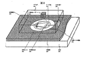
図2は本発明による記録再生ヘッドの構成例のうち、金属散乱体202が他の形状を取る場合の例を示した図である。ここでは金属散乱体202は厚さ20nmのAu薄膜で半導体レーザ200側から見て略七角形の形状をしており、記録膜207を光的もしくは熱的に励起するための強い近接場光208が発生する部分は金属散乱体202外縁の内の近接した5つの頂点からなっており、3点の凸頂点と2点の凹頂点が交互に配置されている。これらの頂点部分の曲率半径は凸部,凹部ともに約20nmとした。
【0020】
図3および図4は本発明による記録再生ヘッドの構成例のうち、金属散乱体がさらに他の配置,形状を取る場合の例を示した図である。図3は図1と同一の金属散乱体を2個備え、近接場光308を発生させる頂点部分を対向させて配置しており、図4は図2と同一の金属散乱体を2個備え、近接場光408を発生させる頂点部分を対向させて配置させた構成となっている。各金属散乱体間の距離は30nmである。
なお本明細書中では金属散乱体の形状が略五角形ないしは略七角形の例をあげて説明を行っているが、散乱体の形状は所望の記録マーク(記録磁区)形状,すなわち記録媒体を光的もしくは熱的に励起して局所的な物理的性質を変化せしめる近接場光の発生領域の形状に応じて適宜調整されるべき物であり、必ずしも多角形に限定されるものではない。また光源である半導体レーザから励起光の照射を受けて内部にプラズモンが励起され得る条件であれば、金属散乱体の材質,大きさ,厚み等は限定されるものではない。同様に半導体レーザは一般的な単一縦モード型の素子であるが、金属散乱体内部にプラズモンを励起し、金属散乱体近傍に強力な近接場光を発生可能であれば、その光出力,発振波長,内部構造等が特別に限定されるものではない。さらに本発明による記録ヘッドは、磁束検出手段等を同一スライダに積載すること等による磁気再生方式との組み合わせにおいてより良好な効果を得ることができるものであるが、記録コイル104,記録コイル電極105およびGMR素子103は、熱磁気記録媒体を例にあげて今後説明を行うために必要な素子であり、本発明の金属散乱体を用いた近接場光による低雑音記録動作に直接関係するものではない。
【0021】
図5は本発明による記録再生ヘッドにおいて、金属散乱体によって発生される近接場光および記録媒体の加熱の様子を説明する図である。図5(a)は金属散乱体の形状をz軸正方向(紙面鉛直上方向)から見た図である。金属散乱体はz軸方向に厚さ30nmを持つAu薄膜であり、その外周部は曲率半径15nmの凹頂点,およびそれを挟んで隣接する曲率半径25nmの2カ所の凸頂点,さらにこの凸頂点に連続する直線部分,曲率半径25nmの凸部および曲率半径150nmの円弧の組み合わせから構成されている。図中の数字は金属散乱体外縁形状の曲率半径を表している。直線部分の成す角は60°であり、散乱体のx方向への長さは150nmである。なお第1〜4図による実施形態の説明例では金属散乱体の形状は略多角形としていたが、例えば図5(a)に示す通り、外周部が厳密に多角形で構成されていることは必ずしも本発明における金属散乱体の必須条件ではない。
【0022】
図5(b)は図5(a)の金属散乱体を厚さ15nmのTbFeCo記録膜表面から10nmの距離に配置し、波長785nmのxy面に平行な平面波を照射した場合の、TbFeCo記録媒体表面における近接場光分布のシミュレーション結果である。図中の実線は近接場光の等強度線,破線は金属散乱体の外縁形状であり、数字は入射光に対する近接場光の強度比を示す。光源からの励起光照射による金属散乱体内におけるプラズモンの励起により、x軸正方向(図中右側)の凸頂点2カ所に入射光の200倍を上回る強力な近接場光が生じている。
【0023】
図5(c)は前述の条件におけるTbFeCo記録膜の表面温度分布のシミュレーション結果である。金属散乱体はTbFeCo記録膜に対して相対速度1m/sでx軸正方向に移動しており、照射時間100ナノ秒の光パルスが照射されたものとした。実線は等温度線,破線は金属散乱体の外縁形状であり、数字は室温からの上昇温度を示す。熱磁気記録によってTbFeCo記録膜に形成される記録磁区形状は、記録膜組成で決定される所定の記録温度の等温線にほぼ一致する。そこでこの記録温度を室温+150℃とすれば、光パルスの照射によって室温+150℃の等温線と同じ形状の空豆型又は略矩形の記録磁区(記録マーク)が形成できることになる。
【0024】
図6は図1で示された本発明による記録再生ヘッドを用いた情報記録再生装置の構成例を示した図である。まず記録または再生動作に並行して行われる記録, 再生位置情報の取得について説明する。すなわち基板616上および基板616上に製膜された記録膜615からなる記録媒体620上にはあらかじめその製造時に、記録媒体620上における物理的位置を示す情報(アドレス情報)が一定の変換規則に従って表された磁区配列として記録されている。このため磁束検出手段であるGMR素子613が記録媒体620の表面を走査すると、その表面における磁区配列を反映した信号,すなわちアドレス情報を示す信号がGMR素子613より出力される。GMR素子613のこの出力信号は増幅器610によって必要なレベルまで増幅された後に、復号器606,アクチュエータ駆動回路609およびアドレス認識回路605に入力される。アドレス認識回路605はGMR素子613からの信号からスライダ614の走査位置を解析し、システム・コントローラ604に伝達する。システム・コントローラ604はGMR素子613の位置情報および外部機器からの記録再生要求に従って、アクチュエータ駆動回路609,記録コイル駆動回路607,レーザ駆動回路608の制御を適宜行う。アクチュエータ駆動回路609はシステム・コントローラ604からの指示およびGMR素子613からの信号に従って、記録媒体620上の所望の位置を金属散乱体617およびGMR素子613が走査するようにVCM(Voice Coil Motor)611の駆動を行う。VCM611はこの駆動信号に従いジンバル・アーム619の先に固定されたスライダ614を移動させ、記録媒体620上の任意位置に位置づける。スライダ614上には、半導体レーザ612,金属散乱体617,GMR素子613,記録コイル618が積載されていることは前述した通りである。
【0025】
情報の記録時においては、記録すべきユーザ・データ600が外部機器とのインタフェース回路601を介してシステム・コントローラ604に送り込まれ、必要に応じてエラー検出,訂正情報等の付加後、符号器603に伝えられる。符号器603はユーザ・データ600を(1,7)変調後NRZI変換を施し、記録媒体620上の記録磁区の配列を反映した信号を生成する。記録波形発生回路602はこの信号を参照し、記録バイアス磁界の制御信号およびレーザ発光強度の制御信号を発生する。磁気コイル駆動回路607はシステム・コントローラ604からの指示を受け、記録バイアス磁界の制御信号に従って記録コイル618を駆動し、金属散乱体617によって強い近接場光が発生される部分に記録バイアス磁界を発生する。またレーザ駆動回路608もシステム・コントローラ604からの指示を受け、レーザ発光強度の制御信号に従って記録エネルギー源である半導体レーザ612を駆動する。半導体レーザ612から出射されたレーザ光621は金属散乱体上617に照射され、金属散乱体617はその形状で決まる近傍領域に強い近接場光を発生させ、記録膜615を加熱する。ここで近接場光による加熱領域は記録コイル618による記録バイアス磁界の印加領域に比べて広いものとする。記録膜615は膜面垂直方向に磁化容易軸を有する垂直磁気記録膜(例えばTbFeCoアモルファス合金膜やPt/Co多層膜等)であり、常温での保磁力は外部から印加される記録バイアス磁界よりも高く、記録時のレーザ光による加熱時の保磁力は記録バイアス磁界よりも低い。この構成を取ることにより、後述する通りレーザ光による加熱および記録バイアス磁界を制御することにより、記録膜上に所望の記録磁区を形成することができる。
【0026】
情報の再生時においては、記録膜615表面をGMR素子613によって走査し、記録磁区の配列を反映した信号を検出する。記録磁区の配列を反映したGMR素子613の出力信号は増幅器610によって必要なレベルまで増幅された後に、アクチュエータ駆動回路609,復号器606およびアドレス認識回路605に入力される。復号器606は符号器603の逆変換を施すことにより記録されていたデータを復元し、復元結果をシステム・コントローラ604に伝える。システム・コントローラ604は必要に応じてエラー検出,訂正等の処理を行い、インタフェース回路601を介して再生されたユーザ・データ600を外部機器に送り出す。
【0027】
なおここでは図2〜図4で示された本発明による記録再生ヘッドを用いた情報記録再生装置の構成例を特別には示さないが、それらに対する構成例は図2の記録再生ヘッド部分を適宜置換したものとして差し支えない。
【0028】
図8は図6で示された本発明による情報記録再生装置の動作例を詳細に説明した図である。今、記録時にユーザ・データ600が符号器603で変換され、記録データ800が得られたものとする。記録データ800は記録波形発生回路602を介して記録コイル駆動回路607に伝えられ、記録膜615上の強い近接場光による加熱位置近傍に記録バイアス磁界802を発生する。この記録バイアス磁界802は記録膜615に垂直に印加される。同時にレーザ駆動回路608はレーザ発光強度801で示す通り、記録トラックに沿った記録磁区長の最小変化単位(検出窓幅)に同期したパルス状に半導体レーザ612を駆動する。強い近接場光によって加熱された領域では記録膜615の保磁力が低下して記録バイアス磁界の絶対値を下回り、その領域の磁化が記録バイアス磁界の方向にならって、記録磁区803に示される通り1回の光パルスの照射では空豆型又は略矩形の領域の磁化方向が決定される。記録膜615は金属散乱体の走査にともない加熱領域の中心を一定間隔で移しながら間欠的に加熱,冷却を繰り返されるので、光パルスの照射間隔を短縮してゆくと前記の空豆型又は略矩形の領域がたがいに重なり合い、光パルスの照射ごとにより細長い空豆型又は略矩形の記録磁区が形成されるかのように記録が行われる。図8中の記録磁区803はこの記録磁区形状を模式的に表したもので、レーザ発光強度801および記録バイアス磁界802に示された通りの記録動作を行った場合に形成される記録膜615上の記録磁区形状を記録膜615真上から見たものである。図8に示されているように、空豆型又は略矩形の記録磁区803は、トラック方向よりもトラック方向に垂直な方向の方が長い形状を有している。ここにおいて、空豆型の記録磁区803トラック中央付近とトラック端付近の磁壁を結んだ線がトラック方向に対して略直交している。図8中において近接場発生領域(スライダ)は左から右に向かって走査し、記録バイアス磁界が正の場合には紙面上向き方向の磁区(メッシュを施した領域)が、記録バイアス磁界が負の場合には紙面下向きの磁区(無色の領域)が形成される。本発明による記録再生ヘッドを用いた記録では、強い近接場光の発生領域が複数の近接場光源の連なった物であるため、前述した単一ピークの光スポットによる記録再生ヘッドを用いた場合に比べ、トラック中央部付近の記録膜における記録時等温線の曲率を小さく(平均的な曲率半径を大きく)することができる。情報の再生時には記録媒体620上をGMR素子613で走査し、再生信号を得る。再生信号はユーザ・データ600が符号器603において変換された結果である記録データ800を反映しており、必要に応じて増幅,等化,2値化,復号等の処理を施されてユーザ・データ600に復元される。記録磁区803をGMR素子813を用いて磁気再生した場合の再生信号波形をGMR再生信号804に示す。本発明による記録では、図7を用いて前述した従来技術による記録に比してトラック中心部分における記録磁区の湾曲が小さく、その結果GMR再生信号804のエッジ部分はGMR再生信号704のエッジ部分に比して急峻な立ち上がりおよび立ち下がりを示している。すなわちGMR再生信号804はGMR再生信号704に比して分解能が高く、情報記録再生装置のサイズおよび情報記録再生装置の信頼性等の点できわめて有利となる。またGMR素子の中心と記録トラックの中心がオフセットした場合でも大きな分解能低下が生じないため、記録時と再生時との間で許容されるトラック・オフセット量が緩和され、さらにトラック両端部分においても磁壁同士が必要以上に接近しないため高密度記録時でも雑音の発生が少なく、情報記録再生装置のサイズ,製造コスト,信頼性の点できわめて有利となる。
【0029】
なお本発明では記録膜のトラック中央部付近における記録時等温線の曲率をなるべく小さくすることが目的であるから、必然的に記録媒体に対する記録再生ヘッドの走査方向,すなわち記録トラックの方向は、図8中の記録磁区803における金属散乱体の模式図に示されているごとく、前記記録媒体に物理的性質の変化を生じせしめる強い近接場光が発生する頂点の配列方向に対しておおむね直交していることが望ましい。またさらにこの場合には記録トラックの幅は1回の光パルス照射ごとに擬似的に形成される磁区の幅に等しいので、前記記録媒体に物理的性質の変化を生じせしめる強い近接場光が発生する頂点間の距離は、必然的にこの記録トラックの幅よりも短くなる。
【0030】
【発明の効果】
本発明によれば、光的あるいは熱的な励起を受けることによって引き起こされる局所的な物理的性質の変化によって情報を保持する記録媒体を用いる記録ヘッド,記録再生ヘッドおよび情報記録再生装置において、微細な記録マーク構造の形成不良にともなう記録雑音の増加が抑えられる。また記録トラック中央付近における記録マークの形状を再生信号検出素子の再生特性に合わせて制御することが出来るので、記録媒体からの再生能力を高めることも可能となる。以上により製造がきわめて困難な再生信号検出素子等を用いることなく記録密度を向上させることが可能となり、情報記録再生装置のサイズおよび情報記録再生装置の製造コスト上昇を抑え、同時に高い信頼性を実現することが可能となる。
【図面の簡単な説明】
【図1】本発明による記録再生ヘッドの構成例を示した図。
【図2】本発明による記録再生ヘッドの構成例のうち、金属散乱体202が他の形状を取る場合の例を示した図。
【図3】本発明による記録再生ヘッドの構成例のうち、金属散乱体がさらに他の配置,形状を取る場合の例を示した図。
【図4】本発明による記録再生ヘッドの構成例のうち、金属散乱体がさらに他の配置,形状を取る場合の例を示した図。
【図5】本発明による記録再生ヘッド内において、金属散乱体によって発生される近接場光および記録媒体の加熱の様子を説明する図。
【図6】図1で示された本発明による記録再生ヘッドを用いた情報記録再生装置の構成例を示した図。
【図7】従来の単一ピークの光スポットによる記録再生ヘッドを用い、垂直記録膜に対して光パルス磁界変調記録を実施した場合の記録過程の例を詳細に説明した図。
【図8】図6で示された本発明による情報記録再生装置の動作例を詳細に説明した図。
【符号の説明】
100,200,300,400,612…半導体レーザ
101,201,301,401,614…スライダ
102,202,302,402,617…金属散乱体
103,203,303,403,613…GMR素子
104,204,304,404,618…記録コイル
108,208,308,408…近接場光
109,209,309,409,621…レーザ光
600…ユーザ・データ
604…システム・コントローラ
607…記録コイル駆動回路
608…レーザ駆動回路
609…アクチュエータ駆動回路
621…レーザ光
700,800…記録データ
701,801…レーザ発光強度
702,802…記録バイアス磁界
703,803…記録磁区
704,804…GMR素子再生信号。[0001]
BACKGROUND OF THE INVENTION
The present invention relates to a recording method for recording information by optically or thermally exciting a recording medium to change the local physical properties of the recording medium, a reproducing method for reproducing the information, or a recording The present invention relates to an information recording head having a function, an information recording / reproducing head having a recording / reproducing function, or an information recording / reproducing apparatus using them.
[0002]
[Prior art]
In “a conventional information recording medium capable of both magneto-optical reproduction and magnetic reproduction and its recording / reproducing apparatus” (first prior art), as disclosed in Japanese Patent Application Laid-Open No. 10-21598 Recording was performed by irradiating the recording light from the light source through the substrate to the magneto-optical recording film formed on the medium and heating it to form a reversed magnetic domain. Information is reproduced by irradiating the above-described magneto-optical recording film with reproduction light from the light source through the substrate to detect the rotation of the polarization plane of the reflected light, and the second magnetic layer on the magneto-optical recording film. This was done by forming a layer and regenerating the leakage flux from this second magnetic layer.
[0003]
In the “magnetic head and manufacturing method thereof” (second prior art) found in Japanese Patent Gazette and Japanese Patent No. 2665022, it corresponds to a substantially crescent-shaped recording magnetic domain formed by optical pulse magnetic field modulation recording or the like. Therefore, a method using a magnetoresistive effect element having a curved recording sensitivity distribution has been disclosed.
[0004]
In the “information recording / reproducing apparatus” (third prior art) found in Japanese Patent Application Laid-Open No. 2000-353301, a perpendicular magnetic recording film formed on the surface of a substrate having a concavo-convex structure on the surface. In an information recording / reproducing apparatus using a recording medium that retains information by the upper recording magnetic domain, a method for improving the recording density by forming the recording magnetic domain in which the track center is placed on the land and the width in the track orthogonal direction is equal to or larger than the land width Has been disclosed.
[0005]
Furthermore, in the “magneto-optical recording medium, the manufacturing method thereof, and the magneto-optical recording / reproducing apparatus” (fourth prior art), which is found in Japanese Patent Application Laid-Open No. 11-126385, It is described that the domain wall formed in the magnetic layer is formed in an arc shape along the rear part of the Curie temperature isotherm of the magnetic material, and the shape of the magnetization region is a crescent shape.
FIG. 7 shows a recording process when optical pulse magnetic field modulation recording is performed on a perpendicular recording film using a conventional recording / reproducing head with a single-peak light spot such as a light spot narrowed down to the diffraction limit by a lens. It is the figure which explained in detail the example of the recording process by the optical pulse magnetic field modulation recording system in the prior art which explained the example in detail. The optical pulse magnetic field modulation recording method is a recording method widely known as optical pulse magnetic field modulation recording which is a kind of thermomagnetic recording. As described below, in the optical pulse magnetic field modulation recording, since the size of the recording magnetic domain (interval between domain walls in the scanning direction) is not easily regulated by the size of the excitation area of the recording medium by the light spot, this method is particularly advantageous in forming a minute recording magnetic domain. It is. In this description, the recording magnetic domain shape by the optical pulse magnetic field modulation recording method is described as an example, but this is not intended to limit the recording method to the optical pulse magnetic field modulation recording method. This is also effective for the DC magneto-optical modulation recording system or the optical modulation recording system, which is the thermomagnetic recording system.
[0006]
Assume that recording data 700 is given at the time of recording. The recording data 700 generates a recording bias
[0007]
[Problems to be solved by the invention]
In general, when performing thermomagnetic recording using a light spot that has been narrowed down to the diffraction limit using a lens, a method using optical pulse magnetic field modulation recording is advantageous because it can ensure a large recording power margin. In this optical pulse magnetic field modulation recording, when a single-peaked substantially circular light spot narrowed down to the diffraction limit using a lens is used, the magnetization direction of the substantially circular region is determined for each light pulse irradiation. As a result, the recorded magnetic domain becomes a crescent. However, when reproducing the crescent-shaped magnetic domain using normal magnetic flux detecting means (for example, GMR element) having a linear sensitivity distribution, there is a problem that the reproduction resolution is lowered. This is because the timing at which the magnetic flux detection means passes on the domain wall varies depending on the distance from the track center, and the response waveform from the recording magnetic domain spreads in the time axis direction. Further, as described in FIG. 11 of the fourth prior art and the explanation part corresponding thereto, the domain wall is very close at the tip of the crescent-shaped recording magnetic domain, so that the formation of the magnetic domain becomes unstable and expected. It is easy to generate a magnetic domain shape. Since the response from this portion is noise (recording noise) different from the originally recorded user data, it prevents normal user data reproduction. As described above, in the first or fourth prior art, the recording density cannot be sufficiently improved due to the problem of the resolution and noise of the reproduced signal, and the size of the information recording / reproducing apparatus and the manufacturing cost and reliability of the information recording / reproducing apparatus are not possible. It was disadvantageous in terms of etc.
[0008]
Also, in the second prior art, when the center of the magnetoresistive effect element and the center of the recording magnetic domain row (recording track) are offset, the resolution is greatly lowered. Therefore, the track offset between recording and reproducing is caused. The amount had to be kept very small. Further, it is difficult to form a magnetoresistive element having a curved sensitivity distribution, and as a result, it is extremely disadvantageous in terms of manufacturing cost of the information recording / reproducing apparatus.
[0009]
Further, the third prior art is disadvantageous in terms of the cost of the information recording medium, because the uneven structure is formed on the substrate surface of the recording medium, and the process of manufacturing the medium becomes complicated. In addition, when a recording / reproducing head / slider using dynamic pressure is lifted to a position very close to the surface of the recording medium, the air film rigidity between the recording medium and the head / slider is reduced, and the slider is likely to crash. It was disadvantageous in terms of device reliability.
[0010]
This will be described with reference to FIG. Near the tip of the crescent-shaped magnetic domain, the domain walls are very close to each other and become unstable, and an unexpected magnetic domain shape that does not reflect the heat distribution during recording tends to occur. When information is reproduced from the recorded magnetic domain, the response from such an unexpected magnetic domain shape part is a noise (recording noise) different from the originally recorded information, which hinders normal user data reproduction. . Further, a reproduction signal waveform when the recording
[0011]
[Means for Solving the Problems]
In order to solve the above problems, a recording head for recording information includes a slider that scans the surface of the recording medium, a light source that is loaded on the slider and supplies recording energy, and the recording medium near the surface of the slider. A scatterer that is formed oppositely and receives light from the light source to excite the recording medium optically or thermally to change local physical properties and record information. The outer edge portion of the scatterer that generates a strong near-field light that causes a change in physical properties is composed of at least two adjacent vertices, and the distance between the vertices is a recording track on the recording medium. The configuration is shorter than the width.
[0012]
In order to solve the above-mentioned object, a recording / reproducing head for recording and reproducing information is provided with a slider that scans the surface of the recording medium, a light source that is loaded on the slider and supplies recording energy, and a surface near the surface of the slider. A scatterer that is formed to face the recording medium, receives light from the light source, excites the recording medium optically or thermally to change local magnetic properties, and records information on the slider. An outer edge portion of the scatterer that has a magnetic flux detection element that locally detects leakage magnetic flux from the surface of the recording medium and generates strong near-field light that causes a change in physical properties of the recording medium. It is composed of at least two adjacent vertices, and the distance between the vertices is shorter than the recording track width on the recording medium.
[0013]
Further, for the purpose of solving the above-mentioned object, in the information recording / reproducing apparatus using the recording medium for holding information by the local change of magnetic property caused by receiving optical or thermal excitation, the recording / reproducing head A recording signal processing unit that drives the light source based on a conversion result obtained by performing a predetermined conversion on user data to form a magnetic domain array corresponding to the user data on the recording medium, and the magnetic flux detection unit. Reproduction signal processing means for restoring the user data by performing the inverse conversion of the conversion, and a scanning mechanism for positioning the slider at an arbitrary position of the recording medium.
[0014]
An information recording method will be described. User data is converted by an encoder to obtain recorded data. The obtained recording data is transmitted to the recording coil drive circuit via the meter generation circuit, and a recording bias magnetic field is generated in the vicinity of the heating position by the strong near-field light on the recording film. The recording bias magnetic field is applied perpendicular to the recording film. At the same time, the laser driving circuit drives the semiconductor laser in a pulse shape synchronized with the minimum change unit of the recording magnetic domain office along the recording track. In the region heated by the near-field light, the retention force of the recording film is reduced to be lower than the absolute value of the recording bias magnetic field, and the magnetization of the region is aligned with the direction of the recording bias magnetic field. The magnetization direction of the mold or the substantially rectangular region is determined. The recording film repeats heating and cooling intermittently while moving the center of the heating area at regular intervals as the metal scatterer scans, and when the irradiation interval of the light pulses is shortened, the substantially rectangular areas overlap each other. Each time the light pulse is irradiated, a long and narrow rectangular recording magnetic domain is formed and recording is performed.
[0015]
At the time of information reproduction, the medium on which information is recorded by the above method is scanned with a GMR element to obtain a reproduction signal. The playback signal reflects the recorded data that is the result of converting the user data in the encoder, and is restored to the user data after being amplified, equalized, binarized, combined, etc. as necessary. Is done.
[0016]
As described above, even when optical pulse magnetic field modulation recording, which is particularly advantageous for high linear density recording, is used, an increase in recording noise due to formation failure of a fine magnetic domain structure can be suppressed. Further, the curvature of the domain wall of the recording magnetic domain near the center of the recording track is reduced, and a decrease in reproduction resolution at the time of magnetic reproduction due to this is suppressed. For this reason, it is possible to improve the recording density even though it is not necessary to use magnetic flux detection means that is difficult to manufacture, or to minimize the amount of track offset allowed between recording and reproduction, This is extremely advantageous in terms of the size of the information recording / reproducing apparatus, the manufacturing cost and reliability of the information recording / reproducing apparatus.
[0017]
DETAILED DESCRIPTION OF THE INVENTION
Hereinafter, specific embodiments of the present invention will be described in detail with reference to the drawings.
[0018]
FIG. 1 is a diagram showing a configuration example of a recording / reproducing head according to the present invention. A recording medium is formed on the back surface (the surface opposite to the surface facing the recording medium) of the
[0019]
FIG. 2 is a diagram showing an example of the configuration of the recording / reproducing head according to the present invention when the metal scatterer 202 takes another shape. Here, the metal scatterer 202 is an Au thin film having a thickness of 20 nm and has a substantially heptagonal shape as viewed from the
[0020]
FIG. 3 and FIG. 4 are diagrams showing an example of a case where the metal scatterer has another arrangement and shape among the configuration examples of the recording / reproducing head according to the present invention. 3 includes two metal scatterers identical to those in FIG. 1, with the apex portions that generate near-
In this specification, the shape of the metal scatterer is described as an example of a substantially pentagon or a heptagon. However, the shape of the scatterer is a desired recording mark (recording domain) shape, that is, the recording medium is light-transmitted. It should be appropriately adjusted according to the shape of the near-field light generation region that changes the local physical properties by excitation or thermal excitation, and is not necessarily limited to a polygon. Further, the material, size, thickness, and the like of the metal scatterer are not limited as long as the plasmon can be excited by being irradiated with excitation light from a semiconductor laser as a light source. Similarly, a semiconductor laser is a common single longitudinal mode type element, but if it can excite plasmons inside the metal scatterer and generate strong near-field light near the metal scatterer, its light output, The oscillation wavelength, internal structure, etc. are not particularly limited. Further, the recording head according to the present invention can obtain a better effect in combination with a magnetic reproducing system by mounting magnetic flux detecting means or the like on the same slider. The GMR element 103 is an element necessary for the following explanation by taking a thermomagnetic recording medium as an example, and is not directly related to the low noise recording operation by the near-field light using the metal scatterer of the present invention. Absent.
[0021]
FIG. 5 is a diagram for explaining the near-field light generated by the metal scatterer and the heating of the recording medium in the recording / reproducing head according to the present invention. FIG. 5A is a view of the shape of the metal scatterer viewed from the positive z-axis direction (upward in the drawing). The metal scatterer is an Au thin film having a thickness of 30 nm in the z-axis direction, and its outer peripheral portion has a concave vertex with a curvature radius of 15 nm, two convex vertices with a curvature radius of 25 nm adjacent to each other, and this convex vertex Are composed of a combination of a straight line portion, a convex portion having a curvature radius of 25 nm, and an arc having a curvature radius of 150 nm. The numbers in the figure represent the radius of curvature of the outer edge shape of the metal scatterer. The angle formed by the straight line portion is 60 °, and the length of the scatterer in the x direction is 150 nm. Although the shape of the metal scatterer is substantially polygonal in the explanation example of the embodiment shown in FIGS. 1 to 4, for example, as shown in FIG. 5 (a), the outer periphery is strictly composed of polygons. This is not necessarily an essential condition of the metal scatterer in the present invention.
[0022]
FIG. 5B shows a TbFeCo recording medium in which the metal scatterer of FIG. 5A is disposed at a distance of 10 nm from the surface of the TbFeCo recording film having a thickness of 15 nm and is irradiated with a plane wave parallel to the xy plane having a wavelength of 785 nm. It is a simulation result of near field light distribution in the surface. The solid line in the figure is the isointensity line of near-field light, the broken line is the outer edge shape of the metal scatterer, and the numbers indicate the intensity ratio of the near-field light to the incident light. Excitation of plasmons in the metal scatterer by excitation light irradiation from a light source generates strong near-field light exceeding 200 times the incident light at two convex vertices in the positive x-axis direction (right side in the figure).
[0023]
FIG. 5C shows a simulation result of the surface temperature distribution of the TbFeCo recording film under the above-described conditions. The metal scatterer was moved in the x-axis positive direction at a relative speed of 1 m / s with respect to the TbFeCo recording film, and was irradiated with a light pulse having an irradiation time of 100 nanoseconds. A solid line is an isothermal line, a broken line is the outer edge shape of a metal scatterer, and a number shows the temperature rise from room temperature. The shape of the recording magnetic domain formed on the TbFeCo recording film by thermomagnetic recording substantially matches the isotherm of a predetermined recording temperature determined by the recording film composition. Therefore, if the recording temperature is room temperature + 150 ° C., a blank bean shape or a substantially rectangular recording magnetic domain (record mark) having the same shape as the isotherm at room temperature + 150 ° C. can be formed by light pulse irradiation.
[0024]
FIG. 6 is a diagram showing a configuration example of an information recording / reproducing apparatus using the recording / reproducing head according to the present invention shown in FIG. First, acquisition of recording and reproduction position information performed in parallel with the recording or reproduction operation will be described. That is, on the recording medium 620 formed of the recording film 615 formed on the substrate 616 and on the substrate 616, information (address information) indicating a physical position on the recording medium 620 is preliminarily manufactured according to a certain conversion rule. It is recorded as the magnetic domain arrangement represented. For this reason, when the GMR element 613 serving as magnetic flux detection means scans the surface of the recording medium 620, a signal reflecting the magnetic domain arrangement on the surface, that is, a signal indicating address information is output from the GMR element 613. This output signal of the GMR element 613 is amplified to a required level by the amplifier 610 and then input to the decoder 606, the actuator drive circuit 609 and the address recognition circuit 605. The address recognition circuit 605 analyzes the scanning position of the slider 614 from the signal from the GMR element 613 and transmits it to the system controller 604. The system controller 604 appropriately controls the actuator drive circuit 609, the recording coil drive circuit 607, and the laser drive circuit 608 in accordance with the position information of the GMR element 613 and a recording / reproduction request from an external device. The actuator drive circuit 609 is configured to scan a desired position on the recording medium 620 in accordance with an instruction from the system controller 604 and a signal from the GMR element 613 so that the metal scatterer 617 and the GMR element 613 scan a desired position on the recording medium 620. Drive. The VCM 611 moves the slider 614 fixed to the tip of the gimbal arm 619 in accordance with this drive signal, and positions it at an arbitrary position on the recording medium 620. As described above, the semiconductor laser 612, the metal scatterer 617, the GMR element 613, and the recording coil 618 are mounted on the slider 614.
[0025]
At the time of recording information, user data 600 to be recorded is sent to the system controller 604 via an interface circuit 601 with an external device, and after adding error detection and correction information as necessary, the encoder 603 To be told. The encoder 603 performs NRZI conversion after (1, 7) modulation on the user data 600, and generates a signal reflecting the arrangement of recording magnetic domains on the recording medium 620. The recording waveform generation circuit 602 refers to this signal and generates a recording bias magnetic field control signal and a laser emission intensity control signal. The magnetic coil driving circuit 607 receives an instruction from the system controller 604, drives the recording coil 618 in accordance with the recording bias magnetic field control signal, and generates a recording bias magnetic field in a portion where strong near-field light is generated by the metal scatterer 617. To do. The laser drive circuit 608 also receives an instruction from the system controller 604 and drives the semiconductor laser 612 which is a recording energy source in accordance with a laser emission intensity control signal.
[0026]
When reproducing information, the surface of the recording film 615 is scanned by the GMR element 613, and a signal reflecting the arrangement of the recording magnetic domains is detected. The output signal of the GMR element 613 reflecting the arrangement of the recording magnetic domains is amplified to a required level by the amplifier 610 and then input to the actuator drive circuit 609, the decoder 606 and the address recognition circuit 605. The decoder 606 restores the recorded data by performing the inverse transformation of the encoder 603 and transmits the restoration result to the system controller 604. The system controller 604 performs processing such as error detection and correction as necessary, and sends the user data 600 reproduced via the interface circuit 601 to an external device.
[0027]
Here, the configuration example of the information recording / reproducing apparatus using the recording / reproducing head according to the present invention shown in FIG. 2 to FIG. 4 is not specifically shown. It can be replaced.
[0028]
FIG. 8 is a diagram illustrating in detail an operation example of the information recording / reproducing apparatus according to the present invention shown in FIG. Now, it is assumed that the user data 600 is converted by the encoder 603 at the time of recording, and the recording data 800 is obtained. The recording data 800 is transmitted to the recording coil drive circuit 607 via the recording waveform generation circuit 602, and a recording bias magnetic field 802 is generated in the vicinity of the heating position by the strong near-field light on the recording film 615. This recording bias magnetic field 802 is applied perpendicularly to the recording film 615. At the same time, the laser drive circuit 608 drives the semiconductor laser 612 in a pulse shape synchronized with the minimum change unit (detection window width) of the recording magnetic domain length along the recording track, as indicated by the laser emission intensity 801. In a region heated by strong near-field light, the coercive force of the recording film 615 decreases and falls below the absolute value of the recording bias magnetic field, and the magnetization in that region follows the direction of the recording bias magnetic field, as shown in the recording magnetic domain 803. In one light pulse irradiation, the magnetization direction of a blank bean type or a substantially rectangular region is determined. The recording film 615 is intermittently heated and cooled while moving the center of the heating region at a constant interval along with the scanning of the metal scatterer. Therefore, when the irradiation interval of the light pulse is shortened, the above-mentioned empty bean type or substantially rectangular shape is obtained. The regions are overlapped with each other, and recording is performed as if an elongated empty bean-shaped or substantially rectangular recording magnetic domain is formed each time the light pulse is irradiated. A recording magnetic domain 803 in FIG. 8 schematically represents the shape of the recording magnetic domain. On the recording film 615 formed when the recording operation as shown in the laser emission intensity 801 and the recording bias magnetic field 802 is performed. This recording magnetic domain shape is viewed from directly above the recording film 615. As shown in FIG. 8, the blank or substantially rectangular recording magnetic domain 803 has a longer shape in the direction perpendicular to the track direction than in the track direction. Here, the line connecting the domain wall near the center of the track and the end of the track is substantially orthogonal to the track direction. In FIG. 8, the near-field generating region (slider) scans from left to right. When the recording bias magnetic field is positive, the magnetic domain (meshed region) in the upward direction on the paper surface is negative and the recording bias magnetic field is negative. In this case, a magnetic domain (colorless region) pointing downward on the paper surface is formed. In the recording using the recording / reproducing head according to the present invention, the region where strong near-field light is generated is a combination of a plurality of near-field light sources. In comparison, the curvature of the recording isotherm in the recording film near the center of the track can be reduced (the average radius of curvature is increased). When reproducing information, the recording medium 620 is scanned by the GMR element 613 to obtain a reproduction signal. The reproduction signal reflects recorded data 800 that is a result of converting the user data 600 in the encoder 603, and is subjected to processing such as amplification, equalization, binarization, and decoding as necessary. The data 600 is restored. A reproduction signal waveform when the recording magnetic domain 803 is magnetically reproduced using the GMR element 813 is shown as a
[0029]
In the present invention, the objective is to reduce the curvature of the recording isotherm near the center of the track of the recording film as much as possible. Therefore, the scanning direction of the recording / reproducing head relative to the recording medium, that is, the direction of the recording track is inevitably shown in FIG. As shown in the schematic diagram of the metal scatterer in the recording magnetic domain 803 in FIG. 8, the recording medium is substantially perpendicular to the arrangement direction of the vertices where strong near-field light that causes a change in physical properties is generated. It is desirable. Furthermore, in this case, the width of the recording track is equal to the width of the magnetic domain that is formed in each light pulse irradiation, so that strong near-field light that causes a change in physical properties is generated on the recording medium. The distance between the vertices is necessarily shorter than the width of the recording track.
[0030]
【The invention's effect】
According to the present invention, in a recording head, a recording / reproducing head, and an information recording / reproducing apparatus using a recording medium that retains information by a local change in physical properties caused by receiving optical or thermal excitation, Increase in recording noise due to poor formation of a recording mark structure can be suppressed. Further, since the shape of the recording mark in the vicinity of the center of the recording track can be controlled in accordance with the reproduction characteristics of the reproduction signal detecting element, it is possible to increase the reproduction ability from the recording medium. As a result, it is possible to improve recording density without using a reproduction signal detection element that is extremely difficult to manufacture, reducing the size of the information recording / reproducing device and the manufacturing cost of the information recording / reproducing device, and simultaneously achieving high reliability. It becomes possible to do.
[Brief description of the drawings]
FIG. 1 is a diagram showing a configuration example of a recording / reproducing head according to the present invention.
FIG. 2 is a diagram showing an example of a configuration of a recording / reproducing head according to the present invention when a metal scatterer 202 takes another shape.
FIG. 3 is a diagram showing an example in which the metal scatterer has another arrangement and shape in the configuration example of the recording / reproducing head according to the present invention.
FIG. 4 is a diagram showing an example of a case where a metal scatterer takes another arrangement and shape in the configuration example of the recording / reproducing head according to the present invention.
FIG. 5 is a diagram for explaining a near-field light generated by a metal scatterer and heating of a recording medium in a recording / reproducing head according to the present invention.
6 is a diagram showing a configuration example of an information recording / reproducing apparatus using the recording / reproducing head according to the present invention shown in FIG. 1;
FIG. 7 is a diagram illustrating in detail an example of a recording process when optical pulse magnetic field modulation recording is performed on a perpendicular recording film using a conventional recording / reproducing head with a single-peak light spot.
FIG. 8 is a diagram illustrating in detail an example of the operation of the information recording / reproducing apparatus according to the present invention shown in FIG. 6;
[Explanation of symbols]
100, 200, 300, 400, 612 ... semiconductor laser
101, 201, 301, 401, 614 ... slider
102,202,302,402,617 ... Metal scatterer
103,203,303,403,613 ... GMR element
104,204,304,404,618 ... Recording coil
108, 208, 308, 408 ... near-field light
109,209,309,409,621 ... Laser light
600: User data
604 ... System controller
607 ... Recording coil drive circuit
608 ... Laser drive circuit
609 ... Actuator drive circuit
621 ... Laser light
700, 800 ... recorded data
701, 801 ... Laser emission intensity
702, 802 ... Recording bias magnetic field
703, 803 ... Recording magnetic domain
704, 804... GMR element reproduction signal.
Claims (6)
記録媒体に記録磁区を形成して情報を記録する際に、前記光源から光を照射することにより近接場光を発生させる散乱体と、
前記散乱体の外縁部分は、前記光照射により内部にプラズモンが励起されて近接場光を発生する少なくとも2点以上の近接した頂点から構成されており、かつ、前記頂点間の距離は、前記記録媒体上における記録トラック幅よりも短く、
前記記録媒体表面からの漏洩磁束を検出する磁束検出素子とを有していることを特徴とする情報記録再生ヘッド。A light source;
A scatterer that generates near-field light by irradiating light from the light source when recording information by forming a recording magnetic domain on a recording medium;
The outer edge portion of the scatterer is composed of at least two adjacent vertices that generate near-field light when plasmons are excited inside by the light irradiation , and the distance between the vertices is the recording distance Shorter than the recording track width on the medium,
An information recording / reproducing head comprising: a magnetic flux detecting element for detecting a leakage magnetic flux from the surface of the recording medium.
記録媒体に記録磁区を形成して情報を記録する際に、前記光源から光を照射することにより近接場光を発生させる散乱体と、
前記散乱体の外縁部分は、前記光照射により内部にプラズモンが励起されて近接場光を発生する少なくとも2点以上の近接した頂点から構成されており、かつ、前記頂点間の距離は、前記記録媒体上における記録トラック幅よりも短く、
前記記録媒体表面からの漏洩磁束を検出する磁束検出素子と、
前記情報を変換する符号器と、
前記変換結果に基づいて前記光源を駆動し、前記記録媒体上に前記情報に対応した磁区配列を形成する記録信号処理手段と、
前記磁束検出手段からの信号に前記変換の逆変換をして前記情報を復元する再生信号処理手段とを有することを特徴とする情報記録再生装置。A light source;
A scatterer that generates near-field light by irradiating light from the light source when recording information by forming a recording magnetic domain on a recording medium;
The outer edge portion of the scatterer is composed of at least two adjacent vertices that generate near-field light when plasmons are excited inside by the light irradiation , and the distance between the vertices is the recording distance Shorter than the recording track width on the medium,
A magnetic flux detection element for detecting leakage magnetic flux from the surface of the recording medium;
An encoder for converting the information;
Recording signal processing means for driving the light source based on the conversion result and forming a magnetic domain array corresponding to the information on the recording medium;
An information recording / reproducing apparatus comprising reproduction signal processing means for restoring the information by performing inverse conversion of the conversion on the signal from the magnetic flux detection means.
散乱体の外縁部分は、前記光照射により内部にプラズモンが励起されて近接場光を発生する少なくとも2点以上の近接した頂点から構成されており、かつ、前記頂点間の距離は、前記記録媒体上における記録トラック幅よりも短く、
前記記録磁区は、空豆型又は略矩形であることを特徴とする情報記録方法。An information recording method for recording information by generating near-field light by irradiating light from a light source to a scatterer to form a recording magnetic domain on a recording medium,
The outer edge portion of the scatterer is composed of at least two adjacent vertices that generate near-field light when plasmons are excited inside by the light irradiation , and the distance between the vertices is the recording medium Shorter than the recording track width above,
The information recording method according to claim 1, wherein the recording magnetic domain is empty beans or substantially rectangular.
Priority Applications (2)
| Application Number | Priority Date | Filing Date | Title |
|---|---|---|---|
| JP2002160906A JP4042472B2 (en) | 2002-06-03 | 2002-06-03 | Information recording / reproducing head, information recording / reproducing apparatus, and information recording method |
| US10/354,063 US7054234B2 (en) | 2002-06-03 | 2003-01-30 | Near-field high density magneto-optical recording head |
Applications Claiming Priority (1)
| Application Number | Priority Date | Filing Date | Title |
|---|---|---|---|
| JP2002160906A JP4042472B2 (en) | 2002-06-03 | 2002-06-03 | Information recording / reproducing head, information recording / reproducing apparatus, and information recording method |
Publications (3)
| Publication Number | Publication Date |
|---|---|
| JP2004005858A JP2004005858A (en) | 2004-01-08 |
| JP2004005858A5 JP2004005858A5 (en) | 2005-06-23 |
| JP4042472B2 true JP4042472B2 (en) | 2008-02-06 |
Family
ID=29561622
Family Applications (1)
| Application Number | Title | Priority Date | Filing Date |
|---|---|---|---|
| JP2002160906A Expired - Fee Related JP4042472B2 (en) | 2002-06-03 | 2002-06-03 | Information recording / reproducing head, information recording / reproducing apparatus, and information recording method |
Country Status (2)
| Country | Link |
|---|---|
| US (1) | US7054234B2 (en) |
| JP (1) | JP4042472B2 (en) |
Families Citing this family (14)
| Publication number | Priority date | Publication date | Assignee | Title |
|---|---|---|---|---|
| JP4325172B2 (en) * | 2002-11-01 | 2009-09-02 | 株式会社日立製作所 | Near-field light generating probe and near-field light generating apparatus |
| US7489597B2 (en) * | 2004-09-27 | 2009-02-10 | Sharp Kabushiki Kaisha | Electromagnetic field generating element, information recording/reproducing head, and information recording/reproducing apparatus |
| JP4095623B2 (en) * | 2005-04-05 | 2008-06-04 | 株式会社日立製作所 | Head for magneto-optical fusion recording apparatus and method for manufacturing the same |
| JP4081480B2 (en) * | 2005-08-19 | 2008-04-23 | 株式会社日立製作所 | Head for magneto-optical fusion recording apparatus and magneto-optical fusion recording apparatus |
| EP2001021B1 (en) * | 2006-03-29 | 2013-12-04 | Panasonic Corporation | Near-field optical head, near-field optical head device, near-field optical information device, and near-field optical information system |
| JP4129031B2 (en) * | 2006-06-12 | 2008-07-30 | 株式会社日立製作所 | Near-field light generator and recording / reproducing apparatus |
| WO2008068973A1 (en) * | 2006-12-07 | 2008-06-12 | Konica Minolta Opto, Inc. | Magnetic recording device and magnetic recording head |
| US7759630B2 (en) * | 2006-12-26 | 2010-07-20 | Hitachi Global Storage Technologies Netherlands B.V. | Method and apparatus for the generation and control of multiple near-field light sources at subwavelength resolution |
| US8243557B2 (en) * | 2006-12-26 | 2012-08-14 | Hitachi Global Storage Technologies Netherlands B.V. | Optimized ridge apertures for thermally assisted magnetic recording |
| US7821732B2 (en) * | 2008-09-25 | 2010-10-26 | Tdk Corporation | Thermally assisted magnetic head having an asymmetric plasmon antenna and manufacturing method thereof |
| US7835102B2 (en) * | 2008-09-26 | 2010-11-16 | Tdk Corporation | Heat assisted magnetic recording head comprising plasmon antenna with flat surfaces opposed to medium |
| US8040760B2 (en) * | 2008-10-16 | 2011-10-18 | Seagate Technology Llc | Polarization near-field transducer having optical conductive blades |
| JP2010146662A (en) * | 2008-12-19 | 2010-07-01 | Sony Corp | Recording and playback device and recording and playback system |
| US8325566B2 (en) * | 2009-03-19 | 2012-12-04 | Tdk Corporation | Thermally-assisted magnetic recording head having a light source at least inclined from an opposed-to-medium surface |
Family Cites Families (13)
| Publication number | Priority date | Publication date | Assignee | Title |
|---|---|---|---|---|
| JP3791971B2 (en) | 1996-07-02 | 2006-06-28 | 富士通株式会社 | Magneto-optical recording medium and recording / reproducing apparatus thereof |
| US5696372A (en) * | 1996-07-31 | 1997-12-09 | Yale University | High efficiency near-field electromagnetic probe having a bowtie antenna structure |
| JPH11126385A (en) | 1997-10-24 | 1999-05-11 | Canon Inc | Magneto-optical recording medium and manufacture thereof, and magneto-optical recording and reproducing device |
| US6560168B1 (en) | 1998-09-02 | 2003-05-06 | Hitachi, Ltd. | Information recording/reproducing device |
| JP2000353301A (en) | 1999-06-11 | 2000-12-19 | Hitachi Ltd | Information recording/reproducing device |
| JP3902952B2 (en) | 2000-03-10 | 2007-04-11 | 株式会社日立グローバルストレージテクノロジーズ | Light-guided thin-film magnetic head |
| JP3882456B2 (en) * | 2000-03-13 | 2007-02-14 | 株式会社日立製作所 | Near-field optical probe, near-field optical microscope and optical recording / reproducing apparatus using the same |
| JP3903365B2 (en) * | 2001-03-29 | 2007-04-11 | 株式会社東芝 | Optically assisted magnetic recording head and optically assisted magnetic recording apparatus |
| JP3793430B2 (en) * | 2001-07-18 | 2006-07-05 | 株式会社日立製作所 | Optical device using near-field light |
| JP4032689B2 (en) * | 2001-10-04 | 2008-01-16 | 株式会社日立製作所 | Measuring device / recording / reproducing device using near-field light |
| KR100436292B1 (en) * | 2001-11-28 | 2004-06-16 | 한국전자통신연구원 | Head for recording and reading optical data and a method of manufacturing the same |
| US6714370B2 (en) * | 2002-01-07 | 2004-03-30 | Seagate Technology Llc | Write head and method for recording information on a data storage medium |
| US7245562B2 (en) * | 2003-08-25 | 2007-07-17 | Koninklijke Philips Electronics N.V. | Method and device for high-speed magnetic recording |
-
2002
- 2002-06-03 JP JP2002160906A patent/JP4042472B2/en not_active Expired - Fee Related
-
2003
- 2003-01-30 US US10/354,063 patent/US7054234B2/en not_active Expired - Fee Related
Also Published As
| Publication number | Publication date |
|---|---|
| JP2004005858A (en) | 2004-01-08 |
| US20030223316A1 (en) | 2003-12-04 |
| US7054234B2 (en) | 2006-05-30 |
Similar Documents
| Publication | Publication Date | Title |
|---|---|---|
| JP4100133B2 (en) | Recording head and information recording apparatus using the same | |
| JP4042472B2 (en) | Information recording / reproducing head, information recording / reproducing apparatus, and information recording method | |
| JP3984568B2 (en) | Magnetic recording apparatus and magnetic recording method | |
| JP4705165B2 (en) | Magnetic sensor element, magnetic reproducing head, magnetic reproducing device, and magnetic reproducing method | |
| JPH0337849A (en) | Method of increasing linear type bit density in photo-electro-magnetic recording medium | |
| JP2010040113A (en) | Magnetic recording method and magnetic recording device | |
| JP4038336B2 (en) | Information recording and playback method | |
| JP4004978B2 (en) | Information recording / reproducing head and information recording / reproducing apparatus | |
| JP3950440B2 (en) | Magnetic recording head, magnetic recording apparatus, and magnetic recording method | |
| US6314061B1 (en) | Linear high density magneto-optical recording apparatus | |
| US6683823B2 (en) | Method for reproducing information on a recording medium | |
| JPH06208739A (en) | Magneto-optic disk and magnetization of the disk | |
| JPS5830656B2 (en) | magneto-optical recording medium | |
| WO2001065547A1 (en) | Method and device for information recording/reproducing and information recording medium | |
| JP2000353301A (en) | Information recording/reproducing device | |
| JP2012038391A (en) | Magnetic head slider and magnetic record replay device | |
| US20030142323A1 (en) | Method for regulating shape of floatation surface of slider floating above record carrier | |
| JP4249662B2 (en) | Thermally assisted recording head and magnetic recording apparatus having the same | |
| JP4381541B2 (en) | Optical information recording method, optical information recording / reproducing method, and optical information recording / reproducing apparatus | |
| JP4294211B2 (en) | Magnetic recording device | |
| JP2007115375A (en) | Magnetic recording and reproducing device | |
| JP4949313B2 (en) | Information recording medium, information recording apparatus, information recording method, and method for manufacturing the information recording medium | |
| JP4404812B2 (en) | Magneto-optical disk unit | |
| JP5097613B2 (en) | Information recording medium, information recording apparatus, information recording method, and method for manufacturing the information recording medium | |
| JPH05189833A (en) | Optical information recording method and recording/ reproducing apparatus |
Legal Events
| Date | Code | Title | Description |
|---|---|---|---|
| A521 | Request for written amendment filed |
Free format text: JAPANESE INTERMEDIATE CODE: A523 Effective date: 20040928 |
|
| A621 | Written request for application examination |
Free format text: JAPANESE INTERMEDIATE CODE: A621 Effective date: 20040928 |
|
| RD01 | Notification of change of attorney |
Free format text: JAPANESE INTERMEDIATE CODE: A7421 Effective date: 20060419 |
|
| A131 | Notification of reasons for refusal |
Free format text: JAPANESE INTERMEDIATE CODE: A131 Effective date: 20070522 |
|
| A521 | Request for written amendment filed |
Free format text: JAPANESE INTERMEDIATE CODE: A523 Effective date: 20070719 |
|
| A131 | Notification of reasons for refusal |
Free format text: JAPANESE INTERMEDIATE CODE: A131 Effective date: 20070828 |
|
| A521 | Request for written amendment filed |
Free format text: JAPANESE INTERMEDIATE CODE: A523 Effective date: 20070912 |
|
| TRDD | Decision of grant or rejection written | ||
| A01 | Written decision to grant a patent or to grant a registration (utility model) |
Free format text: JAPANESE INTERMEDIATE CODE: A01 Effective date: 20071023 |
|
| A61 | First payment of annual fees (during grant procedure) |
Free format text: JAPANESE INTERMEDIATE CODE: A61 Effective date: 20071105 |
|
| FPAY | Renewal fee payment (event date is renewal date of database) |
Free format text: PAYMENT UNTIL: 20101122 Year of fee payment: 3 |
|
| FPAY | Renewal fee payment (event date is renewal date of database) |
Free format text: PAYMENT UNTIL: 20101122 Year of fee payment: 3 |
|
| FPAY | Renewal fee payment (event date is renewal date of database) |
Free format text: PAYMENT UNTIL: 20111122 Year of fee payment: 4 |
|
| FPAY | Renewal fee payment (event date is renewal date of database) |
Free format text: PAYMENT UNTIL: 20111122 Year of fee payment: 4 |
|
| FPAY | Renewal fee payment (event date is renewal date of database) |
Free format text: PAYMENT UNTIL: 20121122 Year of fee payment: 5 |
|
| LAPS | Cancellation because of no payment of annual fees |