JP4042061B2 - Image recording apparatus and supply tray - Google Patents

Image recording apparatus and supply tray Download PDF

Info

Publication number
JP4042061B2
JP4042061B2 JP2004062647A JP2004062647A JP4042061B2 JP 4042061 B2 JP4042061 B2 JP 4042061B2 JP 2004062647 A JP2004062647 A JP 2004062647A JP 2004062647 A JP2004062647 A JP 2004062647A JP 4042061 B2 JP4042061 B2 JP 4042061B2
Authority
JP
Japan
Prior art keywords
recording medium
supply
supply tray
guide
image recording
Prior art date
Legal status (The legal status is an assumption and is not a legal conclusion. Google has not performed a legal analysis and makes no representation as to the accuracy of the status listed.)
Expired - Fee Related
Application number
JP2004062647A
Other languages
Japanese (ja)
Other versions
JP2005247542A (en
Inventor
貴俊 竹本
哲男 浅田
良章 今枝
Current Assignee (The listed assignees may be inaccurate. Google has not performed a legal analysis and makes no representation or warranty as to the accuracy of the list.)
Brother Industries Ltd
Original Assignee
Brother Industries Ltd
Priority date (The priority date is an assumption and is not a legal conclusion. Google has not performed a legal analysis and makes no representation as to the accuracy of the date listed.)
Filing date
Publication date
Application filed by Brother Industries Ltd filed Critical Brother Industries Ltd
Priority to JP2004062647A priority Critical patent/JP4042061B2/en
Priority to CNB2005100531976A priority patent/CN100404272C/en
Priority to CNU2005200073155U priority patent/CN2900176Y/en
Priority to EP05251296.9A priority patent/EP1570997B1/en
Priority to US11/071,257 priority patent/US7437119B2/en
Publication of JP2005247542A publication Critical patent/JP2005247542A/en
Application granted granted Critical
Publication of JP4042061B2 publication Critical patent/JP4042061B2/en
Anticipated expiration legal-status Critical
Expired - Fee Related legal-status Critical Current

Links

Images

Classifications

    • BPERFORMING OPERATIONS; TRANSPORTING
    • B41PRINTING; LINING MACHINES; TYPEWRITERS; STAMPS
    • B41JTYPEWRITERS; SELECTIVE PRINTING MECHANISMS, i.e. MECHANISMS PRINTING OTHERWISE THAN FROM A FORME; CORRECTION OF TYPOGRAPHICAL ERRORS
    • B41J13/00Devices or arrangements of selective printing mechanisms, e.g. ink-jet printers or thermal printers, specially adapted for supporting or handling copy material in short lengths, e.g. sheets
    • B41J13/10Sheet holders, retainers, movable guides, or stationary guides
    • B41J13/103Sheet holders, retainers, movable guides, or stationary guides for the sheet feeding section
    • BPERFORMING OPERATIONS; TRANSPORTING
    • B65CONVEYING; PACKING; STORING; HANDLING THIN OR FILAMENTARY MATERIAL
    • B65HHANDLING THIN OR FILAMENTARY MATERIAL, e.g. SHEETS, WEBS, CABLES
    • B65H1/00Supports or magazines for piles from which articles are to be separated
    • B65H1/26Supports or magazines for piles from which articles are to be separated with auxiliary supports to facilitate introduction or renewal of the pile
    • B65H1/266Support fully or partially removable from the handling machine, e.g. cassette, drawer
    • BPERFORMING OPERATIONS; TRANSPORTING
    • B65CONVEYING; PACKING; STORING; HANDLING THIN OR FILAMENTARY MATERIAL
    • B65HHANDLING THIN OR FILAMENTARY MATERIAL, e.g. SHEETS, WEBS, CABLES
    • B65H3/00Separating articles from piles
    • B65H3/02Separating articles from piles using friction forces between articles and separator
    • B65H3/06Rollers or like rotary separators
    • BPERFORMING OPERATIONS; TRANSPORTING
    • B65CONVEYING; PACKING; STORING; HANDLING THIN OR FILAMENTARY MATERIAL
    • B65HHANDLING THIN OR FILAMENTARY MATERIAL, e.g. SHEETS, WEBS, CABLES
    • B65H2301/00Handling processes for sheets or webs
    • B65H2301/40Type of handling process
    • B65H2301/42Piling, depiling, handling piles
    • B65H2301/423Depiling; Separating articles from a pile
    • B65H2301/4232Depiling; Separating articles from a pile of horizontal or inclined articles, i.e. wherein articles support fully or in part the mass of other articles in the piles
    • B65H2301/42324Depiling; Separating articles from a pile of horizontal or inclined articles, i.e. wherein articles support fully or in part the mass of other articles in the piles from top of the pile
    • B65H2301/423245Depiling; Separating articles from a pile of horizontal or inclined articles, i.e. wherein articles support fully or in part the mass of other articles in the piles from top of the pile the pile lying on a stationary support, i.e. the separator moving according to the decreasing height of the pile
    • BPERFORMING OPERATIONS; TRANSPORTING
    • B65CONVEYING; PACKING; STORING; HANDLING THIN OR FILAMENTARY MATERIAL
    • B65HHANDLING THIN OR FILAMENTARY MATERIAL, e.g. SHEETS, WEBS, CABLES
    • B65H2403/00Power transmission; Driving means
    • B65H2403/50Driving mechanisms
    • B65H2403/51Cam mechanisms
    • B65H2403/513Cam mechanisms involving elongated cam, i.e. parallel to linear transport path
    • BPERFORMING OPERATIONS; TRANSPORTING
    • B65CONVEYING; PACKING; STORING; HANDLING THIN OR FILAMENTARY MATERIAL
    • B65HHANDLING THIN OR FILAMENTARY MATERIAL, e.g. SHEETS, WEBS, CABLES
    • B65H2405/00Parts for holding the handled material
    • B65H2405/30Other features of supports for sheets
    • B65H2405/32Supports for sheets partially insertable - extractable, e.g. upon sliding movement, drawer

Landscapes

  • Engineering & Computer Science (AREA)
  • Mechanical Engineering (AREA)
  • Sheets, Magazines, And Separation Thereof (AREA)
  • Pile Receivers (AREA)

Description

本発明は、画像記録装置及び供給トレイに関する。   The present invention relates to an image recording apparatus and a supply tray.

従来より、プリンタ、複写機、ファクシミリ等の画像記録装置として、装置本体に対して着脱可能な供給トレイを備え、この供給トレイに積載されたシート状の被記録媒体を供給手段により画像記録手段へ供給して、その被記録媒体上に画像を記録するものが知られている。このような画像記録装置として、例えば下記の特許文献1に記載されたものがある。この特許文献1に記載の画像記録装置では、供給手段として、装置本体に設けられた支軸を中心に回動可能なアーム部材と、そのアーム部材の揺動端に設けられた供給ローラとを備えており、供給ローラが供給トレイに積載された最上層の被記録媒体に当接して、その被記録媒体を供給ローラの回転により画像記録手段側へ送り出すように構成されている。   2. Description of the Related Art Conventionally, as an image recording apparatus such as a printer, a copier, or a facsimile, a supply tray that can be attached to and detached from the apparatus main body has been provided. One that supplies and records an image on the recording medium is known. As such an image recording apparatus, for example, there is one described in Patent Document 1 below. In the image recording apparatus described in Patent Document 1, as supply means, an arm member that can be rotated around a support shaft provided in the apparatus main body, and a supply roller provided at the swing end of the arm member. The supply roller is in contact with the uppermost recording medium stacked on the supply tray, and the recording medium is sent to the image recording means side by the rotation of the supply roller.

このような構成の装置においては、供給トレイを装置本体に対して着脱する際に、供給ローラが供給トレイの奥壁に衝突するのを回避する必要がある。そこで、前述の特許文献1に記載の画像記録装置では、供給トレイに固定配置されている側壁部に所定の傾斜面を有するカム部を形成し、供給トレイを装置本体から取り外す際に、アーム部材がカム部の案内によって揺動され、供給ローラが供給トレイの奥壁を乗り越えるように構成されている。
特開2002−249242公報
In the apparatus having such a configuration, it is necessary to avoid the supply roller from colliding with the inner wall of the supply tray when the supply tray is attached to and detached from the apparatus main body. Therefore, in the above-described image recording apparatus described in Patent Document 1, a cam portion having a predetermined inclined surface is formed on the side wall portion fixedly disposed on the supply tray, and the arm member is removed when the supply tray is removed from the apparatus main body. Is swung by the guide of the cam portion, and the supply roller is configured to climb over the back wall of the supply tray.
JP 2002-249242 A

ところで、供給トレイの中には、被記録媒体の供給方向と直交する方向に変位可能な側端部ガイドを設けて、様々なサイズの被記録媒体を位置決めできるようにしたものがある。このような側端部ガイドを上述の特許文献1のものの構成に追加しようとした場合には、使用可能な最大幅まで拡げた状態における側端部ガイドのさらに外側にカム部が形成された固定の側壁部を設けることになり、その分、供給トレイの幅寸法が大きくなってしまうという問題がある。   By the way, some supply trays are provided with side end guides that can be displaced in a direction orthogonal to the recording medium supply direction so that recording media of various sizes can be positioned. When such a side end guide is to be added to the configuration of the above-mentioned Patent Document 1, the cam portion is formed on the outer side of the side end guide in a state where the side end guide is expanded to the maximum usable width. Therefore, there is a problem that the width dimension of the supply tray is increased correspondingly.

本発明は上記のような事情に基づいて完成されたものであって、小型化を図ることの可能な画像記録装置及び供給トレイを提供することを目的とする。   The present invention has been completed based on the above circumstances, and an object thereof is to provide an image recording apparatus and a supply tray that can be reduced in size.

上記の目的を達成するための手段として、請求項1の発明は、シート状の被記録媒体を積載可能で、かつ装置本体に対して引き出し及び挿入可能な供給トレイと、当該供給トレイに前記被記録媒体の供給方向に沿って設けられ、その被記録媒体の供給方向と直交する方向に変位可能な側端部ガイドと、前記装置本体内に設けられ前記被記録媒体に対して画像を記録する画像記録手段と、前記装置本体内で前記被記録媒体の供給方向と直交する方向に延設された支軸を中心に揺動可能なアーム部材と、当該アーム部材の揺動端側に設けられ前記供給トレイが前記装置本体に挿入されたときに、前記供給トレイに積載された最上層の被記録媒体に当接し、それを前記画像記録手段側に送り出す供給ローラと、前記側端部ガイドに設けられ前記供給トレイの底面からの高さが前記被記録媒体の供給方向に沿って変化するカム部と、前記アーム部材と一体的に設けられ、前記供給トレイが前記装置本体に対して引き出し及び収納される際に前記側端部ガイドのカム部に摺接して変位することで、前記供給ローラが被記録媒体の供給方向における最下流側に配された前記供給トレイの奥壁を乗り越えるように前記アーム部材を揺動させる従動部とを有するところに特徴を有する。   As means for achieving the above object, the invention of claim 1 is characterized in that a sheet-like recording medium can be stacked and can be pulled out and inserted into the apparatus main body, and the supply tray has the cover. A side end guide provided along the supply direction of the recording medium and displaceable in a direction perpendicular to the supply direction of the recording medium, and an image recorded on the recording medium provided in the apparatus main body. An image recording means; an arm member swingable about a support shaft extending in a direction orthogonal to the supply direction of the recording medium in the apparatus main body; and provided on the swing end side of the arm member. When the supply tray is inserted into the apparatus main body, the supply roller contacts the uppermost recording medium stacked on the supply tray and feeds it to the image recording means side, and the side end guide Provided said supply A cam portion whose height from the bottom surface of the ray changes along the supply direction of the recording medium and the arm member are integrally provided, and the supply tray is pulled out and stored in the apparatus main body. The arm member is moved so as to slide over the rear wall of the supply tray arranged on the most downstream side in the supply direction of the recording medium. It has a feature in that it has a driven portion that swings.

請求項2の発明は、請求項1に記載のものにおいて、前記供給トレイにおける前記被記録媒体の積載面は前記供給方向の下流側が低くなるように傾斜しているところに特徴を有する。   The invention of claim 2 is characterized in that, in the invention of claim 1, the stack surface of the recording medium in the supply tray is inclined so that the downstream side in the supply direction is lowered.

請求項3の発明は、請求項1または2に記載のものにおいて、前記アーム部材は、前記供給ローラの両端部に設けられその供給ローラの回転軸を受ける軸受け部を有した一対の支持アームを備えて構成され、その支持アーム間に前記支軸からの駆動を前記供給ローラに伝達する動力伝達機構が組み込まれているところに特徴を有する。   According to a third aspect of the present invention, in the first or second aspect, the arm member includes a pair of support arms each having a bearing portion provided at both ends of the supply roller and receiving a rotation shaft of the supply roller. And a power transmission mechanism for transmitting the drive from the support shaft to the supply roller between the support arms.

請求項4の発明は、請求項1から3のいずれかに記載のものにおいて、前記側端部ガイドは、前記被記録媒体の幅方向に間隔を隔てて一対設けられると共に、一方の側端部ガイドから他方の側端部ガイドに向かって延出されて前記被記録媒体の供給方向に間隔を隔てて対向しその対向部にラックギヤを有するリニアガイドバーを備え、前記各リニアガイドバー間には前記ラックギヤと噛み合うピニオンギアが前記供給トレイに回転自在に設けられているところに特徴を有する。   According to a fourth aspect of the present invention, there is provided the apparatus according to any one of the first to third aspects, wherein the pair of side end guides are provided at a distance in the width direction of the recording medium, and one side end portion is provided. A linear guide bar that extends from the guide toward the other side end guide and is opposed to the recording medium in the supply direction with an interval therebetween, and has a rack gear at the opposed portion, and is provided between the linear guide bars. A pinion gear that meshes with the rack gear is characterized in that it is rotatably provided on the supply tray.

請求項5の発明は、請求項1から4のいずれかに記載のものにおいて、前記画像記録手段は前記装置本体内において前記供給トレイの上方に位置するように配置され、前記供給トレイの前記奥壁は前記供給ローラに押し出された前記被記録媒体の先端側を上向きに案内するガイド板により構成されているところに特徴を有する。   According to a fifth aspect of the present invention, in the apparatus according to any one of the first to fourth aspects, the image recording means is disposed in the apparatus main body so as to be positioned above the supply tray, and the back of the supply tray is arranged. The wall is characterized in that it is constituted by a guide plate that guides the leading end side of the recording medium pushed out by the supply roller upward.

請求項6の発明は、請求項5に記載のものにおいて、前記ガイド板のうち幅方向の中央部分は他よりも手前側に膨出し、その膨出端に重なって供給された前記被記録媒体を分離するための分離部材が設けられているところに特徴を有する。   According to a sixth aspect of the present invention, in the recording medium according to the fifth aspect, the central portion in the width direction of the guide plate bulges to the near side of the other, and the recording medium is supplied so as to overlap the bulged end. It is characterized in that a separating member is provided for separating the.

請求項7の発明は、請求項6に記載のものにおいて、前記ガイド板における前記分離部材の幅方向の両側には回転自在な供給補助ローラが設けられているところに特徴を有する。   A seventh aspect of the invention is characterized in that, in the sixth aspect of the invention, a rotatable auxiliary supply roller is provided on both sides of the guide plate in the width direction of the separating member.

請求項8の発明は、請求項1から7のいずれかに記載のものにおいて、前記供給トレイの前部には、前記側端部ガイドを最大幅まで拡げたときにそれらの側端部ガイドとほぼ面一に連なる固定側壁部が対をなして設けられているところに特徴を有する。   According to an eighth aspect of the present invention, in the apparatus according to any one of the first to seventh aspects, the front end portion of the supply tray includes a side end guide when the side end guide is expanded to the maximum width. It is characterized in that fixed side wall portions that are substantially flush with each other are provided in pairs.

請求項9の発明は、請求項8に記載のものにおいて、前記両固定側壁部の上端部には、前記供給トレイに積載された被記録媒体を上方から覆い、かつ前記画像記録手段から送り出された被記録媒体を支持可能なカバー部が延設されているところに特徴を有する。   According to a ninth aspect of the present invention, in the apparatus according to the eighth aspect, the upper ends of the fixed side wall portions cover the recording medium loaded on the supply tray from above and are sent out from the image recording means. Further, the present invention is characterized in that a cover portion capable of supporting the recording medium is extended.

請求項10の発明は、請求項9に記載のものにおいて、前記カバー部には幅方向の中央部分に前方に開放する切欠部が形成されているところに特徴を有する。   A tenth aspect of the invention is characterized in that, in the ninth aspect of the invention, the cover portion is formed with a notch portion that opens forward in a central portion in the width direction.

請求項11の発明は、請求項9または10に記載のものにおいて、前記供給トレイの前部には補助支持部材が前方に引き出し可能に設けられているところに特徴を有する。   The invention of claim 11 is characterized in that, in the invention of claim 9 or 10, an auxiliary support member is provided at the front portion of the supply tray so that it can be pulled out forward.

請求項12の発明は、支軸を中心に揺動可能な供給ローラを備えた画像記録装置に使用される供給トレイであって、前記画像記録装置の備えた装置本体に対して引き出し及び挿入可能とされるとともに、複数のシート状の被記録媒体を積載可能とされ、かつ積載された被記録媒体から一の被記録媒体を前記供給ローラと協働して前記装置本体側に供給する供給トレイにおいて、被記録媒体の供給方向に沿って設けられ、その被記録媒体の供給方向と直交する方向に変位可能な側端部ガイドと、当該側端部ガイドに設けられ、この給紙トレイを前記装置本体に対して引き出し及び挿入する際に前記供給ローラを揺動させる揺動手段とを備えるところに特徴を有する。   According to a twelfth aspect of the present invention, there is provided a supply tray for use in an image recording apparatus provided with a supply roller that can swing around a support shaft, and can be pulled out and inserted into a main body of the image recording apparatus. And a supply tray that can stack a plurality of sheet-like recording media and supplies one recording medium from the stacked recording media to the apparatus main body side in cooperation with the supply roller. A side end guide provided along the supply direction of the recording medium and displaceable in a direction perpendicular to the supply direction of the recording medium, and provided in the side end guide. It is characterized in that it comprises swinging means for swinging the supply roller when it is pulled out and inserted into the apparatus main body.

請求項13の発明は、請求項12に記載のものにおいて、前記揺動手段は、前記側端部ガイドの上端部に、前記供給トレイの底面からの高さが前記被記録媒体の供給方向に沿って変化するように形成されたカム部を備えているところに特徴を有する。   According to a thirteenth aspect of the present invention, in the twelfth aspect of the present invention, the swinging means has a height from a bottom surface of the supply tray in the supply direction of the recording medium. It has a feature in that it is provided with a cam portion formed so as to change along it.

請求項14の発明は、請求項12または13に記載のものにおいて、前記被記録媒体の積載面は前記供給方向の下流側が低くなるように傾斜しているところに特徴を有する。   A fourteenth aspect of the present invention is characterized in that, in the recording medium according to the twelfth or thirteenth aspect, the stack surface of the recording medium is inclined so that the downstream side in the supply direction is lowered.

請求項15の発明は、請求項12から14のいずれかに記載のものにおいて、前記側端部ガイドは、前記被記録媒体の幅方向に間隔を隔てて一対設けられると共に、一方の側端部ガイドから他方の側端部ガイドに向かって延出されて前記被記録媒体の供給方向に間隔を隔てて対向しその対向部にラックギヤを有するリニアガイドバーを備え、前記各リニアガイドバー間には前記ラックギヤと噛み合うピニオンギアが回転自在に設けられているところに特徴を有する。   According to a fifteenth aspect of the invention, there is provided the apparatus according to any one of the twelfth to fourteenth aspects, wherein the pair of side end guides are provided at a distance in the width direction of the recording medium, and one side end portion is provided. A linear guide bar that extends from the guide toward the other side end guide and is opposed to the recording medium in the supply direction with an interval therebetween, and has a rack gear at the opposed portion, and is provided between the linear guide bars. A pinion gear that meshes with the rack gear is characterized in that it is rotatably provided.

請求項16の発明は、請求項12から15のいずれかに記載のものにおいて、前記供給トレイの前記奥壁は前記供給ローラに押し出された前記被記録媒体の先端側を上向きに案内するガイド板により構成されているところに特徴を有する。   A sixteenth aspect of the present invention is the guide plate according to any one of the twelfth to fifteenth aspects, wherein the back wall of the supply tray guides the leading end side of the recording medium pushed out by the supply roller upward. It has the characteristics in the place comprised by.

請求項17の発明は、請求項16に記載のものにおいて、前記ガイド板のうち幅方向の中央部分は他よりも手前側に膨出し、その膨出端に重なって供給された前記被記録媒体を分離するための分離部材が設けられているところに特徴を有する。   According to a seventeenth aspect of the present invention, in the recording medium according to the sixteenth aspect, the central portion in the width direction of the guide plate bulges to the near side of the other, and the recording medium is supplied so as to overlap the bulged end. It is characterized in that a separating member is provided for separating the.

請求項18の発明は、請求項17に記載のものにおいて、前記ガイド板における前記分離部材の幅方向の両側には回転自在な供給補助ローラが設けられているところに特徴を有する。   The invention according to claim 18 is characterized in that, in the invention according to claim 17, a supply auxiliary roller which is rotatable is provided on both sides of the guide plate in the width direction of the separating member.

請求項19の発明は、請求項12から18のいずれかに記載のものにおいて、前記供給トレイの前部には、前記側端部ガイドを最大幅まで拡げたときにそれらの側端部ガイドとほぼ面一に連なる固定側壁部が対をなして設けられているところに特徴を有する。   According to a nineteenth aspect of the present invention, in the apparatus according to any one of the twelfth to eighteenth aspects, when the side end guides are expanded to the maximum width at the front portion of the supply tray, It is characterized in that fixed side wall portions that are substantially flush with each other are provided in pairs.

請求項20の発明は、請求項19に記載のものにおいて、前記両固定側壁部の上端部には、積載された被記録媒体を上方から覆い、かつ前記装置本体側から送り出された被記録媒体を支持可能なカバー部が延設されているところに特徴を有する。   According to a twentieth aspect of the present invention, in the recording medium according to the nineteenth aspect, the recording medium stacked on the upper end portions of the fixed side wall portions covers the stacked recording medium from above and is sent out from the apparatus main body side. It is characterized in that a cover portion capable of supporting the above is extended.

請求項21の発明は、請求項20に記載のものにおいて、前記カバー部には幅方向の中央部分に前方に開放する切欠部が形成されているところに特徴を有する。   The invention of claim 21 is characterized in that, in the invention of claim 20, the cover part is formed with a notch part that opens forward in the center part in the width direction.

請求項22の発明は、請求項20または21に記載のものにおいて、前記被記録媒体の積載面の前部には前方に引き出し可能な補助支持部材が設けられているところに特徴を有する。   A twenty-second aspect of the invention is characterized in that, in the twenty-first or twenty-first aspect, an auxiliary support member that can be pulled out forward is provided at the front portion of the stacking surface of the recording medium.

<請求項1、12及び13の発明>
供給トレイを引き出し及び挿入する際に供給ローラを持ち上げるためのカム部(揺動手段)を側端部ガイドに設けたため、供給トレイの側壁部を省略でき、その分供給トレイの幅寸法を小さくして装置の小型化を図ることが可能になる。
<Invention of Claims 1, 12, and 13>
Since the side end portion guide is provided with a cam portion (swinging means) for lifting the supply roller when the supply tray is pulled out and inserted, the side wall portion of the supply tray can be omitted, and the width of the supply tray is reduced accordingly. This makes it possible to reduce the size of the apparatus.

<請求項2及び14の発明>
被記録媒体が積載された供給トレイを装置本体から引き出す場合には、被記録媒体をその上面に載った供給ローラの下側から抜き出す必要があり、仮に供給トレイの積載面が水平面であった場合には、供給トレイを引き出すと共に被記録媒体が供給ローラに引っ掛かってしまうおそれがある。これに対し本構成では、供給トレイの積載面が被記録媒体の供給方向の下流側(後側)が低くなるように傾斜しているため、供給トレイを引き出す際には、被記録媒体が上面に載った供給ローラに対して下方へ離間するように引き出される。従って、被記録媒体が供給ローラに引っ掛かりにくくなり、供給トレイを円滑に引き出すことができる。
<Invention of Claims 2 and 14>
When pulling out the supply tray loaded with the recording medium from the main body of the apparatus, it is necessary to pull out the recording medium from the lower side of the supply roller placed on the upper surface, and the loading tray has a horizontal surface. In this case, the supply tray may be pulled out and the recording medium may be caught by the supply roller. On the other hand, in this configuration, the stacking surface of the supply tray is inclined so that the downstream side (rear side) in the supply direction of the recording medium is low. It is pulled out so as to be separated downward with respect to the supply roller placed on the surface. Accordingly, the recording medium is hardly caught by the supply roller, and the supply tray can be pulled out smoothly.

<請求項3の発明>
アーム部材が供給ローラを支持する一対の支持アームを備え、その支持アーム間に支軸からの駆動を供給ローラに伝達する動力伝達機構が組み込まれているため、アーム部材の構成をコンパクトにすることができる。
<Invention of Claim 3>
Since the arm member has a pair of support arms that support the supply roller, and a power transmission mechanism that transmits the drive from the support shaft to the supply roller is incorporated between the support arms, the structure of the arm member is made compact. Can do.

<請求項4及び15の発明>
一対の側端部ガイドがリニアガイドバー及びピニオンギアを介して連動するため、位置合わせの作業性が良い。
<Invention of Claims 4 and 15>
Since the pair of side end guides are interlocked via the linear guide bar and the pinion gear, the alignment workability is good.

<請求項5及び16の発明>
供給トレイの奥壁がガイド板になっているため、供給ローラにより押し出された被記録媒体の先端がこのガイド板によって上向きに案内される。
<Invention of Claims 5 and 16>
Since the back wall of the supply tray is a guide plate, the leading end of the recording medium pushed out by the supply roller is guided upward by the guide plate.

<請求項6及び17の発明>
ガイド板のうち膨出した中央部分に分離部材が設けられているため、被記録媒体が確実に分離部材に当接して分離される。
<Invention of Claims 6 and 17>
Since the separating member is provided in the bulged central portion of the guide plate, the recording medium is reliably brought into contact with the separating member and separated.

<請求項7及び18の発明>
分離部材の両側に供給補助ローラが設けられているため、分離部材により分離された被記録媒体が供給補助ローラに当接して円滑に搬送される。
<Invention of Claims 7 and 18>
Since the auxiliary supply rollers are provided on both sides of the separation member, the recording medium separated by the separation member is brought into contact with the supply auxiliary roller and smoothly conveyed.

<請求項8及び19の発明>
供給トレイには、変位可能な側端部ガイドだけではなく、その前側に固定側壁部が設けられているため、手に保持し易い。また固定側壁部は、側端部ガイドとほぼ面一に連なる位置に設けられているため、供給トレイの幅寸法が大きくならない。
<Invention of Claims 8 and 19>
Since the supply tray is provided not only with the displaceable side end guide but also with a fixed side wall portion on the front side thereof, it is easy to hold in the hand. Moreover, since the fixed side wall portion is provided at a position that is substantially flush with the side end portion guide, the width dimension of the supply tray does not increase.

<請求項9及び20の発明>
供給トレイにカバー部を設けて、供給トレイが排出された被記録媒体を受けるトレイを兼ねる構成としたため、装置全体がコンパクトになる。
<Invention of Claims 9 and 20>
Since the supply tray is provided with a cover portion and also serves as a tray that receives the recording medium discharged from the supply tray, the entire apparatus becomes compact.

<請求項10及び21の発明>
カバー部の幅方向の中央に切欠部が形成されているため、排出された被記録媒体を摘み出し易い。
<Invention of Claims 10 and 21>
Since the notch is formed at the center in the width direction of the cover, it is easy to pick out the discharged recording medium.

<請求項11及び22の発明>
補助支持部材を引き出すことで、排出された被記録媒体が落下しないように支持することができる。また、補助支持部材は不要なときは押し込んでおけるので、邪魔にならない。
<Invention of Claims 11 and 22>
By pulling out the auxiliary support member, the discharged recording medium can be supported so as not to fall. In addition, the auxiliary support member can be pushed in when not needed, so that it does not get in the way.

次に本発明の一実施形態を図1から図12を参照して説明する。
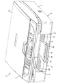
図1は本実施形態における画像記録装置1の外観斜視図、図2は画像記録装置1の断面図である。なお、以下の説明においては、上下方向については図2を基準とし、前後方向については図2の左側を前方とする。
Next, an embodiment of the present invention will be described with reference to FIGS.
FIG. 1 is an external perspective view of an image recording apparatus 1 according to the present embodiment, and FIG. 2 is a cross-sectional view of the image recording apparatus 1. In the following description, the vertical direction is based on FIG. 2, and the left side of FIG.

本実施形態の画像記録装置1は、ファクシミリ機能、プリンタ機能、複写機能、スキャナ機能等を備えた複合機である。この画像記録装置1は、全体として略箱形のケーシング2を備えており、このケーシング2は上方から視て一辺がA4サイズの用紙の長手寸法よりも一回り大きな略正方形状をなしている。ケーシング2は、略箱形の装置本体3と、その上面に覆い付けられるカバー体4とに分割して構成されている。カバー体4は、装置本体3に対して開閉可能とされ、画像を読み取るための読み取りユニット5や操作パネル6等を備えている。   The image recording apparatus 1 according to the present embodiment is a multifunction machine having a facsimile function, a printer function, a copying function, a scanner function, and the like. The image recording apparatus 1 includes a substantially box-shaped casing 2 as a whole, and the casing 2 has a substantially square shape whose one side is slightly larger than the longitudinal dimension of a sheet of A4 size when viewed from above. The casing 2 is divided into a substantially box-shaped device main body 3 and a cover body 4 covered on the upper surface thereof. The cover body 4 can be opened and closed with respect to the apparatus main body 3 and includes a reading unit 5 and an operation panel 6 for reading an image.

装置本体3には、幅方向の中央部に前方に開口した開口部8が設けられ、その開口部8の下部が用紙やOHP用シート等のシート状の被記録媒体(図示せず)を積載する供給トレイ9を収納可能なトレイ収納部10とされている。開口部8の奥側(後側)には、トレイ収納部10の上方に被記録媒体に画像を形成する画像記録手段11が配置されている。さらに、画像記録手段11の奥側には、外側弧状ガイド13と内側弧状ガイド14とが設けられ、両弧状ガイド13,14間にはトレイ収納部10内の供給トレイ9の先端と画像記録手段11の後端側とを接続するUターン状の自由通路15が構成されている。また、画像記録手段11と供給トレイ9との間には、供給トレイ9の被記録媒体を画像記録手段11側へ供給する供給手段16が設けられている。この画像記録装置1においては、図2に矢印で示すように、供給トレイ9に積載された被記録媒体が、供給手段16によって自由通路15に送られ、自由通路15を通過して画像記録手段11に至り、その画像記録手段11において所定の画像を記録した後に、供給トレイ9の前部上面に排出されるようになっている。なお、装置本体3内には、供給手段16等を駆動する駆動手段(図示せず)や各部の動作を制御する制御回路(図示せず)等も設けられている。   The apparatus body 3 is provided with an opening 8 opened forward in the center in the width direction, and a lower portion of the opening 8 is loaded with a sheet-like recording medium (not shown) such as a sheet or an OHP sheet. The supply tray 9 is configured as a tray storage unit 10 that can store the supply tray 9. On the back side (rear side) of the opening 8, an image recording unit 11 that forms an image on a recording medium is disposed above the tray storage unit 10. Further, an outer arc-shaped guide 13 and an inner arc-shaped guide 14 are provided on the back side of the image recording means 11, and between the arc-shaped guides 13 and 14, the leading end of the supply tray 9 in the tray storage unit 10 and the image recording means. A U-turn-shaped free passage 15 connecting the rear end side of 11 is formed. A supply unit 16 is provided between the image recording unit 11 and the supply tray 9 to supply the recording medium on the supply tray 9 to the image recording unit 11 side. In the image recording apparatus 1, as shown by arrows in FIG. 2, the recording medium loaded on the supply tray 9 is sent to the free path 15 by the supply means 16, passes through the free path 15 and is recorded by the image recording means. 11, after a predetermined image is recorded by the image recording means 11, it is discharged onto the upper surface of the front portion of the supply tray 9. The apparatus main body 3 is also provided with drive means (not shown) for driving the supply means 16 and the like, a control circuit (not shown) for controlling the operation of each part, and the like.

次に各部の構成について詳細に説明する。
まず供給トレイ9について図3及び図4等を参照して説明する。なお、図3は、供給トレイ9の平面図であり、図4は、供給トレイ9と装置本体3側に設けられた供給手段16の斜視図である。供給トレイ9は、前述のトレイ収納部10から前方へ水平に引き出すことで装置本体3から取り外し可能とされており、取り外した状態からトレイ収納部10内に水平に挿入することで再び装置本体3内に収納可能となっている。供給トレイ9は、長方形の底板18を備えており、全体として上方から視た大きさが概ねA4サイズ大の薄皿状をなしている。底板18は、その上面に被記録媒体を積載可能とされており、その上面のうち略後半領域が後側積載面19A、略前半領域が前側積載面19Bとされている。両積載面19A,19Bは、ともに後側、即ち被記録媒体の供給方向の下流側が低くなるように傾斜しており、前側積載面19Bは後側積載面19Aよりもさらに傾斜角が大きくされている(図2参照)。
Next, the configuration of each unit will be described in detail.
First, the supply tray 9 will be described with reference to FIGS. 3 is a plan view of the supply tray 9, and FIG. 4 is a perspective view of the supply means 16 provided on the supply tray 9 and the apparatus main body 3 side. The supply tray 9 is detachable from the apparatus main body 3 by being pulled out forward from the tray storage unit 10 described above, and is again inserted into the tray storage unit 10 from the detached state in the apparatus main body 3 again. It can be stored inside. The supply tray 9 is provided with a rectangular bottom plate 18 and has a thin plate shape with a size as viewed from above, which is generally A4 size. The bottom plate 18 is configured such that a recording medium can be stacked on the upper surface thereof. The upper half of the upper surface of the bottom plate 18 is a rear loading surface 19A, and the substantially first half region is a front loading surface 19B. Both the stacking surfaces 19A and 19B are inclined so that the rear side, that is, the downstream side in the recording medium supply direction is lower, and the front stacking surface 19B has an inclination angle larger than that of the rear stacking surface 19A. (See FIG. 2).

後側積載面19A上には、一対の側端部ガイド20R,20Lが左右に互いに間隔を隔てて設けられている。各側端部ガイド20R,20Lは、後側積載面19Aに沿い、かつ後側積載面19Aの後端よりもやや前方位置から後側積載面19Aの前端付近まで延びた底壁部21を備えている。各底壁部21における底板18の幅方向外側の端部からは、底壁部21と同じ長さで、かつ前後方向(即ち被記録媒体の供給方向)に沿ったガイド壁22が垂直に立設されている。また、各底壁部21の底面からは、互いに他方の側端部ガイド20R,20Lに向かってリニアガイドバー23が延設されている。両リニアガイドバー23は、前後方向に所定間隔を隔てて並行に配置されるとともに、それぞれ底板18に左右方向に沿って設けられた溝部24内に嵌合されている。両側端部ガイド20R,20Lは、底壁部21を後側積載面19Aに摺接させるとともに、リニアガイドバー23を溝部24に沿って摺動させることで左右方向(即ち被記録媒体の供給方向に直交する方向)に変位可能とされている。また、両リニアガイドバー23には、互いの対向部にラックギア25が形成されており、各ラックギア25はそれぞれ底板18における幅方向の中央位置に回転自在に設けられたピニオンギア26と噛み合っている。このように両側端部ガイド20R,20Lは、ラックギア25とピニオンギア26とを介して互いに連結されることで、常に両ガイド壁22から底板18の幅方向中央までの距離が等しくなるように、互いに連動するようになっている。なお、両側端部ガイド20R,20Lを最大幅まで拡げたとき(図3の状態)には、両ガイド壁22間の間隔がほぼA4サイズの短手寸法(幅寸法)に等しくなる。   On the rear loading surface 19A, a pair of side end guides 20R and 20L are provided on the left and right sides with a space therebetween. Each side end guide 20R, 20L includes a bottom wall portion 21 that extends along the rear loading surface 19A and extends from a position slightly ahead of the rear end of the rear loading surface 19A to the vicinity of the front end of the rear loading surface 19A. ing. From the end of each bottom wall portion 21 on the outer side in the width direction of the bottom plate 18, a guide wall 22 having the same length as the bottom wall portion 21 and along the front-rear direction (that is, the recording medium supply direction) stands vertically. It is installed. Further, a linear guide bar 23 extends from the bottom surface of each bottom wall portion 21 toward the other side end guides 20R and 20L. Both linear guide bars 23 are arranged in parallel in the front-rear direction at a predetermined interval, and are fitted in groove portions 24 provided on the bottom plate 18 along the left-right direction. The side end guides 20R and 20L slide the linear guide bar 23 along the groove 24 while sliding the bottom wall portion 21 to the rear stacking surface 19A, and thus the left and right direction guides (that is, the recording medium supply direction). It is possible to displace in a direction orthogonal to In addition, rack gears 25 are formed on the linear guide bars 23 at opposing portions, and each rack gear 25 meshes with a pinion gear 26 that is rotatably provided at the center position in the width direction of the bottom plate 18. . In this way, the side end guides 20R and 20L are connected to each other via the rack gear 25 and the pinion gear 26, so that the distance from the both guide walls 22 to the center in the width direction of the bottom plate 18 is always equal. They are linked to each other. When the side end guides 20R and 20L are expanded to the maximum width (the state shown in FIG. 3), the distance between the two guide walls 22 is substantially equal to the short dimension (width dimension) of the A4 size.

また、両側端部ガイド20R,20Lにおけるガイド壁22の前端寄り上端部からは、互いに底壁部21の上方へ張出部28が延出して設けられている。各張出部28の後端にはストッパ29がほぼ垂直に立設されている。これらのストッパ29は、後述する排出ローラ99の下方に位置しており、排出された被記録媒体が張出部28上から後方へ移動するのを規制する。また、右側の側端部ガイド20Rの前部には、両側端部ガイド20R,20Lを所望の位置に位置決めするための位置調整部30が設けられている。この位置調整部30は、底壁部21、ガイド壁22及び張出部28の各面に沿った断面コの字形状をなす弾性片30Aを有しており、弾性片30Aに外力を加えない状態では弾性片30Aの下面に設けられた係止突起(図示せず)が、後側積載面19A上に左右方向に沿って設けられた凹凸状のずれ止め部30Bに係止することで、側端部ガイド20R,20Lが位置決めされる。また、弾性片30Aの上端に設けられた操作部30Cを摘むことで、弾性片30Aが撓み変形して前述の係止突起とずれ止め部30Bとの係合が解除され、両側端部ガイド20R,20Lを左右方向に変位できるようになる。
なお、後側積載面19Aにおける幅方向の中央には、起立及び倒伏可能な位置決めリブ31が前後一対設けられており、この位置決めリブ31を起立状態とすることで、後側積載面19Aの後端に設けられた後述のガイド板43との間に、はがきサイズやL判サイズ等の被記録媒体を位置決めできるようになっている。
Further, overhanging portions 28 are provided so as to extend above the bottom wall portion 21 from the upper end portions near the front end of the guide wall 22 in the side end portion guides 20R and 20L. A stopper 29 is erected substantially vertically at the rear end of each overhanging portion 28. These stoppers 29 are located below a discharge roller 99 described later, and restrict the discharged recording medium from moving from the overhanging portion 28 to the rear. Further, a position adjusting unit 30 for positioning the side end guides 20R and 20L at a desired position is provided at the front of the right side end guide 20R. The position adjusting unit 30 has an elastic piece 30A having a U-shaped cross section along each surface of the bottom wall portion 21, the guide wall 22, and the overhang portion 28, and does not apply an external force to the elastic piece 30A. In the state, the locking protrusion (not shown) provided on the lower surface of the elastic piece 30A is locked to the uneven displacement preventing portion 30B provided along the left-right direction on the rear loading surface 19A. The side end guides 20R and 20L are positioned. Further, by pinching the operating portion 30C provided at the upper end of the elastic piece 30A, the elastic piece 30A is bent and deformed, and the engagement between the above-described locking projection and the stopper portion 30B is released, and both side end guides 20R. , 20L can be displaced in the left-right direction.
A pair of front and rear positioning ribs 31 are provided at the center of the rear loading surface 19A in the width direction. The positioning ribs 31 are placed in a standing state so that the rear loading surface 19A A recording medium having a postcard size, L size, or the like can be positioned between a guide plate 43 (described later) provided at the end.

底板18上における前側積載面19Bに対応した領域の両側端位置には、それぞれ前後方向に沿った固定側壁部32が垂直に立設されている。これらの固定側壁部32は、両側端部ガイド20R,20Lを最大幅まで拡げたときに、各ガイド壁22とほぼ面一に連なるように配置されている。また、両固定側壁部32の上端部には、底板18上に積載された被記録媒体を上方から覆うことの可能なカバー部33が両固定側壁部32間を跨ぐように延設されている。このカバー部33は、両側端部に設けられた嵌合縁部34を各固定側壁部32の上端部に上方から嵌合させることで取り付けられており、両固定側壁部32に対して着脱可能とされている。また、カバー部33は、全体として前側積載面19Bと概ね並行となるように後下がりに傾斜している。カバー部33の上面には、その後縁部に沿って隆起部35が設けられており、前述した各側端部ガイド20R,20Lの張出部28の前端が概ね隆起部の高さと同程度の高さ位置となっている。さらに、カバー部33には、幅方向の中央部分に前方に開放する切欠部36が形成されている。   Fixed side wall portions 32 are erected vertically in the front-rear direction at both side end positions of the region corresponding to the front loading surface 19B on the bottom plate 18. These fixed side wall portions 32 are disposed so as to be substantially flush with the respective guide walls 22 when the side end guides 20R and 20L are expanded to the maximum width. Further, a cover portion 33 capable of covering the recording medium loaded on the bottom plate 18 from above is extended at the upper end portions of the fixed side wall portions 32 so as to straddle between the fixed side wall portions 32. . The cover portion 33 is attached by fitting fitting edges 34 provided at both end portions to the upper end portions of the fixed side wall portions 32 from above, and is attachable to and detachable from both the fixed side wall portions 32. It is said that. Further, the cover portion 33 is inclined rearward and downward so as to be substantially parallel to the front loading surface 19B as a whole. A raised portion 35 is provided on the upper surface of the cover portion 33 along the rear edge thereof, and the front ends of the overhang portions 28 of the side end guides 20R and 20L described above are substantially the same as the height of the raised portion. It is in the height position. Further, the cover portion 33 is formed with a notch portion 36 that opens forward at the center in the width direction.

底板18における前側積載面19Bには、幅方向中央に前方に開口した長方形の支持部材収納孔38が凹設されており、この支持部材収納孔38内には平面形状が同じく長方形の板状の補助支持部材39が装着されている。補助支持部材39は、前後方向に変位可能とされており、不使用時には、図2に実線で示すように、全体が支持部材収納孔38内に収納され、使用時には、図2に二点鎖線で示すように、支持部材収納孔38から前方へ所定長さ引き出されるようになっている。また、補助支持部材39の前部には、左右に細長い指掛け孔40が上下に貫通して設けられており、また支持部材収納孔38の底面にも指掛け孔40に対応した位置に第2指掛け孔41が設けられている。   The front loading surface 19B of the bottom plate 18 has a rectangular support member accommodation hole 38 opened forward in the center in the width direction. The support member accommodation hole 38 has a rectangular plate-like shape in plan view. An auxiliary support member 39 is attached. The auxiliary support member 39 is displaceable in the front-rear direction. When the auxiliary support member 39 is not used, the auxiliary support member 39 is entirely accommodated in the support member accommodation hole 38 as shown by a solid line in FIG. As shown in FIG. 2, the support member storage hole 38 is drawn forward by a predetermined length. In addition, finger support holes 40 that are elongated in the left and right directions are provided in the front portion of the auxiliary support member 39, and a second finger support is provided on the bottom surface of the support member storage hole 38 at a position corresponding to the finger support hole 40. A hole 41 is provided.

底板18の後端部には、その全幅にわたってガイド板43が取り付けられている。このガイド板43は、その前面が上向きに傾斜しており、後述の供給手段16が底板18に積載された複数の被記録媒体をガイド板43側に押し出すと、そのうち一の被記録媒体が分離されるとともに、その被記録媒体の先端が上向きに案内されるようになっている。また、ガイド板43は、幅方向(左右方向)の中央部が前方に膨出するように若干湾曲しており、その中央部の膨出端に重なるように金属製の分離部材44が取り付けられている。この分離部材44は、上下に所定間隔で並んだ複数の歯部を有するとともに、各歯部の先端がわずかにガイド板43の前面から突出しており、供給手段16によって押し出された複数の被記録媒体がこれらの歯部の先端に当接することで一の被記録媒体が分離されるようになっている。さらに、ガイド板43の中央の膨出端には、分離部材44の幅方向の両側上端部に、回転自在な一対の供給補助ローラ45が設けられている。   A guide plate 43 is attached to the rear end portion of the bottom plate 18 over its entire width. The front surface of the guide plate 43 is inclined upward, and when a later-described supply unit 16 pushes a plurality of recording media stacked on the bottom plate 18 to the guide plate 43 side, one of the recording media is separated. In addition, the leading end of the recording medium is guided upward. The guide plate 43 is slightly curved so that the central portion in the width direction (left-right direction) bulges forward, and a metal separation member 44 is attached so as to overlap the bulging end of the central portion. ing. The separating member 44 has a plurality of tooth portions arranged vertically at a predetermined interval, and the tips of the tooth portions slightly protrude from the front surface of the guide plate 43, and a plurality of recording targets pushed out by the supply unit 16. One recording medium is separated when the medium abuts against the tips of these teeth. Furthermore, a pair of rotatable supply auxiliary rollers 45 are provided at the upper end portions of the separation member 44 in the width direction at the center bulging end of the guide plate 43.

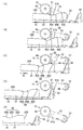
右側の側端部ガイド20Rには、供給トレイ9を装置本体3に対して引き出し及び挿入する際に、供給ローラ52及びアーム部材53を揺動させるカム部60(本発明の「揺動手段」)が設けられている。カム部60は、側端部ガイド20Rにおけるガイド壁22の後部上端部に、底板18の底面からの高さが前後方向に沿って変化するように設けられており、図6に示すように、後下がりに傾斜した斜面60Aと、後上がりに傾斜した斜面60Bと、底板18の底面からの高さがほぼ一定の水平部60Cとが前方から後方へ順に連なることで形成されている。なお、水平部60Cはガイド壁22のほぼ後端まで形成されており、ガイド板43の上端部と同程度の高さを有している。   The right side end guide 20R includes a cam portion 60 that swings the supply roller 52 and the arm member 53 when the supply tray 9 is pulled out and inserted into the apparatus body 3 (the “swinging means” of the present invention). ) Is provided. The cam portion 60 is provided at the rear upper end portion of the guide wall 22 in the side end guide 20R so that the height from the bottom surface of the bottom plate 18 changes along the front-rear direction, as shown in FIG. A slope 60A inclined downward, a slope 60B inclined upward, and a horizontal portion 60C having a substantially constant height from the bottom surface of the bottom plate 18 are formed in order from the front to the rear. The horizontal portion 60 </ b> C is formed almost to the rear end of the guide wall 22, and has the same height as the upper end portion of the guide plate 43.

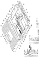
次に被記録媒体の供給手段16について図2及び図5等を参照して説明する。なお、図5は、供給手段16の斜視図である。
装置本体3内には、供給トレイ9の後部上方位置に、左右方向に細長い箱形のフレーム47が設けられており、このフレーム47内に回転可能な支軸48が左右方向(被記録媒体の供給方向と直交する方向)に延設され、供給手段16全体がこの支軸48によって支持されている。支軸48は、ほぼ供給トレイ9の幅方向の中央から右端にわたる範囲に配置されている。また、この支軸48における供給トレイ9の幅方向外側の端部、より詳細には底板18の側端よりやや外側の端部位置には大ギア49が取り付けられている。この大ギア49は図示しない駆動手段に連結されており、駆動手段の動力により支軸48が回転されるようになっている。また、支軸48のもう一方の端部には、支軸48とほぼ同径の小ギア50が取り付けられている。
Next, the recording medium supply means 16 will be described with reference to FIGS. FIG. 5 is a perspective view of the supply means 16.
A box-shaped frame 47 that is elongated in the left-right direction is provided in the apparatus main body 3 at a position above the rear portion of the supply tray 9. The entire supply means 16 is supported by the support shaft 48. The support shaft 48 is arranged in a range from the center in the width direction of the supply tray 9 to the right end. Further, a large gear 49 is attached to an end portion of the support shaft 48 on the outer side in the width direction of the supply tray 9, more specifically, an end portion position slightly outside the side end of the bottom plate 18. The large gear 49 is connected to drive means (not shown), and the support shaft 48 is rotated by the power of the drive means. Further, a small gear 50 having substantially the same diameter as that of the support shaft 48 is attached to the other end portion of the support shaft 48.

支軸48における供給トレイ9の幅方向中央側の端部には、供給ローラ52を支持するアーム部材53が取り付けられている。アーム部材53は、支軸48から径方向外側へ延出し、かつ左右に離間して平行に配された一対の支持アーム54を備えている。両支持アーム54の先端(揺動端)の間には、供給ローラ52が挟まれて配置されるとともに、供給ローラ52の回転軸が支持アーム54に設けられた軸受け部55に支持されることで、供給ローラ52が左右方向を軸として回転可能に保持されている。また、両支持アーム54間には、支軸48の小ギア50と供給ローラ52の有するギア部52Aとを連結する4つの動力伝達ギア56(本発明の「動力伝達機構」に相当)が支持アーム54の延長方向に連なって組み込まれており、駆動手段によって支軸48が回転されると、その回転力が4つの動力伝達ギア56を介して供給ローラ52に伝達されるようになっている。なお、4つの動力伝達ギア56のうち小ギア50に直接噛み合った動力伝達ギア56Aはいわゆるワンウェイギアであって、支軸48側からの回転力を供給ローラ52側に伝達し、供給ローラ52側からの回転力は支軸48側に伝達しないように構成されている。   An arm member 53 that supports the supply roller 52 is attached to the end of the support shaft 48 on the center side in the width direction of the supply tray 9. The arm member 53 includes a pair of support arms 54 that extend radially outward from the support shaft 48 and that are spaced in parallel to the left and right. A supply roller 52 is sandwiched between the tips (swinging ends) of both support arms 54 and the rotation shaft of the supply roller 52 is supported by a bearing portion 55 provided on the support arm 54. Thus, the supply roller 52 is held rotatably about the left-right direction. Further, between the support arms 54, four power transmission gears 56 (corresponding to the “power transmission mechanism” of the present invention) for connecting the small gear 50 of the support shaft 48 and the gear portion 52A of the supply roller 52 are supported. The arm 54 is incorporated in the extending direction, and when the support shaft 48 is rotated by the driving means, the rotational force is transmitted to the supply roller 52 via the four power transmission gears 56. . Of the four power transmission gears 56, the power transmission gear 56A directly meshed with the small gear 50 is a so-called one-way gear, which transmits the rotational force from the support shaft 48 side to the supply roller 52 side. Is not transmitted to the support shaft 48 side.

アーム部材53は、供給ローラ52の回転軸が支軸48よりも下がった後下がりの傾斜姿勢から、供給ローラ52の回転軸が支軸48の中心とほぼ同じ高さとなる水平姿勢まで揺動可能であり、アーム部材53が水平姿勢になったときには、アーム部材53及び供給ローラ52の大部分がフレーム47内に収容される。複数の被記録媒体を積載した供給トレイ9がトレイ収納部10の正規の取付位置に装着されたときには、アーム部材53の揺動端が自重により下がって供給ローラ52が最上層の被記録媒体の上面に載る。この状態から、供給ローラ52を図2の反時計回り方向に回転させることによって、被記録媒体を後方に押し出し、その被記録媒体の先端側を前述したガイド板43に押し付けることで一の被記録媒体を分離し、自由通路15側に送るようになっている。なお、供給トレイ9の後側積載面19A上には、被記録媒体のない状態で供給ローラ52に当接可能な位置に被記録媒体に対する摩擦係数の大きいコルク板57が貼り付けられており、これにより供給トレイ9に積載される被記録媒体の最後の一枚を供給ローラ52により容易に送り出せるようにしている。   The arm member 53 can swing from an inclined posture in which the rotation axis of the supply roller 52 is lowered after being lowered from the support shaft 48 to a horizontal posture in which the rotation shaft of the supply roller 52 is substantially the same height as the center of the support shaft 48. When the arm member 53 is in the horizontal posture, most of the arm member 53 and the supply roller 52 are accommodated in the frame 47. When the supply tray 9 loaded with a plurality of recording media is mounted at the proper mounting position of the tray storage unit 10, the swinging end of the arm member 53 is lowered by its own weight, and the supply roller 52 is the uppermost recording medium. Place on top. From this state, by rotating the supply roller 52 counterclockwise in FIG. 2, the recording medium is pushed backward, and the leading end side of the recording medium is pressed against the above-described guide plate 43 to obtain one recording target. The medium is separated and sent to the free passage 15 side. A cork plate 57 having a large coefficient of friction with respect to the recording medium is affixed to the rear stacking surface 19A of the supply tray 9 at a position where the recording medium is not in contact with the supply roller 52. As a result, the last sheet of the recording medium loaded on the supply tray 9 can be easily sent out by the supply roller 52.

供給手段16には、供給トレイ9を装置本体3に対して引き出し及び挿入する際に、カム部60及びガイド板43と協働して、供給ローラ52及びアーム部材53を揺動させる従動部61が設けられている。この従動部61は、アーム部材53における支軸48側の支持アーム54の下端部から支軸48に沿って延出して一体的に設けられ、全体として支持アーム54の下端面とほぼ面一な板状をなしている。供給トレイ9が正規の取付位置に取り付けられた状態において、アーム部材53と反対側の従動部61の端部は、ほぼ供給トレイ9の側端位置まで延出しているので、従動部61は、側端部ガイド20Rの左右方向の位置に関わらず、そのガイド壁22の上方に位置するようになっている。また、従動部61の後縁部61Aは、やや上向きに折り曲げられており、支軸48の中心からこの後縁部61Aまでの距離は、支軸48の中心から供給ローラ52の回転軸までの距離の半分弱となっている。後に詳述するように、この従動部61は、供給トレイ9を引き出し及び挿入する際に、その下面がカム部60またはガイド板43に摺接することで上下に変位し、アーム部材53が揺動されるようになっている。   The supply unit 16 includes a driven unit 61 that swings the supply roller 52 and the arm member 53 in cooperation with the cam unit 60 and the guide plate 43 when the supply tray 9 is pulled out and inserted into the apparatus main body 3. Is provided. The follower 61 extends integrally from the lower end of the support arm 54 on the support shaft 48 side of the arm member 53 along the support shaft 48, and is substantially flush with the lower end surface of the support arm 54 as a whole. It has a plate shape. In the state where the supply tray 9 is attached at the regular attachment position, the end of the driven portion 61 opposite to the arm member 53 extends almost to the side end position of the supply tray 9, so that the driven portion 61 is Regardless of the position of the side end guide 20R in the left-right direction, the side end guide 20R is positioned above the guide wall 22. Further, the rear edge portion 61A of the driven portion 61 is bent slightly upward, and the distance from the center of the support shaft 48 to the rear edge portion 61A is from the center of the support shaft 48 to the rotation shaft of the supply roller 52. It is a little less than half the distance. As will be described in detail later, when the supply tray 9 is pulled out and inserted, the driven portion 61 is displaced vertically by sliding the lower surface thereof in contact with the cam portion 60 or the guide plate 43, and the arm member 53 swings. It has come to be.

次に外側弧状ガイド13について図7から図12を参照して説明する。図7は、画像記録装置1の一部を拡大した断面図、図8は、外側弧状ガイド13を斜め後上方から見た斜視図、図9は外側弧状ガイド13を斜め前下方から見た斜視図、図10は外側弧状ガイド13の側面図、図11は外側弧状ガイド13を取り外した状態の画像記録装置1の一部を示す斜視図、図12は外側弧状ガイド13を取り付けた状態の画像記録装置1の一部を示す斜視図である。   Next, the outer arcuate guide 13 will be described with reference to FIGS. 7 is an enlarged cross-sectional view of a part of the image recording apparatus 1, FIG. 8 is a perspective view of the outer arc-shaped guide 13 as viewed from the obliquely rear upper side, and FIG. 9 is a perspective view of the outer arc-shaped guide 13 as viewed from the obliquely lower front. 10 is a side view of the outer arcuate guide 13, FIG. 11 is a perspective view showing a part of the image recording apparatus 1 with the outer arcuate guide 13 removed, and FIG. 12 is an image with the outer arcuate guide 13 attached. 2 is a perspective view showing a part of the recording apparatus 1. FIG.

外側弧状ガイド13は、画像記録手段11の後方、供給トレイ9の後端部の上方位置に取り付けられており、ケーシング2の後面に開口して設けられたガイド取付孔63を通して着脱可能とされている(図2を併せて参照)。外側弧状ガイド13の全体はケーシング2内に収容され、外側弧状ガイド13の後端部はケーシング2の後面とほぼ一致している。外側弧状ガイド13は、幅方向に長く略弧状に湾曲した本体部64を備えており、その本体部64には被記録媒体を案内する外側案内面65が自由通路15に面して形成されている。この外側案内面65は、左右方向について供給トレイ9とほぼ同範囲にわたって形成されている。また、外側案内面65における上流側の端部は、ガイド板43の上端部に位置しており、外側案内面65の下流側の端部は、後述する画像記録手段11の被記録媒体挿入口95を構成するレジストローラ93及び従動ローラ94の直前に位置している。外側案内面65は、上流側の端部付近ではほぼ垂直であり、そこから下流側に向かうにつれて、次第に前方に傾斜し、水平になった後に、前下がりに傾斜して下流側の端部に至るような略弧状をなしている。なお、外側案内面65のうち下流側の端部近傍は平坦面になっている。外側案内面65には、被記録媒体を搬送する方向に沿った複数のリブ66が幅方向に所定間隔で並んで突出して設けられている。また、外側案内面65のうち下流側端部付近は、幅方向の中央部分が自由通路15側へ張り出しており、そのため幅方向の中央側のリブ66Aは他の位置のリブ66に比べて自由通路15側への張り出し寸法が大きくなっている。   The outer arcuate guide 13 is attached to the rear of the image recording means 11 and above the rear end of the supply tray 9 and is detachable through a guide attachment hole 63 provided in the rear surface of the casing 2. (See also FIG. 2). The entire outer arc guide 13 is accommodated in the casing 2, and the rear end portion of the outer arc guide 13 substantially coincides with the rear surface of the casing 2. The outer arc-shaped guide 13 includes a main body portion 64 that is long in the width direction and is curved in a substantially arc shape. An outer guide surface 65 that guides the recording medium is formed on the main body portion 64 so as to face the free passage 15. Yes. The outer guide surface 65 is formed over substantially the same range as the supply tray 9 in the left-right direction. An upstream end portion of the outer guide surface 65 is positioned at the upper end portion of the guide plate 43, and a downstream end portion of the outer guide surface 65 is a recording medium insertion port of the image recording means 11 described later. It is located immediately before the registration roller 93 and the driven roller 94 that constitute 95. The outer guide surface 65 is substantially vertical in the vicinity of the upstream end, and gradually inclines forward from the downstream side toward the downstream side, and after being leveled, the outer guide surface 65 inclines forward and drops to the downstream end. It is almost arc-shaped. Note that the vicinity of the downstream end portion of the outer guide surface 65 is a flat surface. On the outer guide surface 65, a plurality of ribs 66 along the direction in which the recording medium is transported are provided so as to protrude in the width direction at predetermined intervals. Further, in the vicinity of the downstream side end portion of the outer guide surface 65, the central portion in the width direction protrudes toward the free passage 15, so that the rib 66A on the center side in the width direction is free compared to the ribs 66 at other positions. The overhanging dimension toward the passage 15 is increased.

本体部64には、外側案内面65における幅方向の中央部であって、張出部分よりも下流側に取付凹部67が凹設されており、その取付凹部67に湾曲した板状の抵抗低減部68が取り付けられている。外側弧状ガイド13は、本体部64及び抵抗低減部68を含めて全体が合成樹脂材からなり、抵抗低減部68は、被記録媒体に対する摩擦抵抗が他の部分を構成する合成樹脂材よりも小さい合成樹脂材によって形成されている。具体的には、抵抗低減部68は、例えばポリアセタール樹脂(POM)等から形成され、他の部分は例えばポリスチレン樹脂(PS)等から形成される。抵抗低減部68の表面には、本体部64の外側案内面65に概ね倣った形状の案内面69が形成され、その案内面69には、本体部64における前述の張出部分に設けられたリブ66Aに連なって、被記録媒体の搬送方向に沿った複数のリブ70が突出して設けられている。なお、抵抗低減部68のリブ70は、上流側端部付近の突出寸法が本体部64側のリブ66A上端部の突出寸法よりもやや小さくされている。これにより、成形誤差等に起因して抵抗低減部68側のリブ70の下端が本体部64側のリブ66Aよりも突出したために、下方から送られる被記録媒体の先端が抵抗低減部68側のリブ70に引っ掛かるような事態が防止される。また、抵抗低減部68の案内面69には、下流側端部付近の幅方向中央位置に、後述するレジセンサ88の有する検知片90の先端を受け入れ可能な検知片受入孔71が凹設されている。この検知片受入孔71は、被記録媒体の搬送方向に沿って細長く、その幅方向両側の開口縁部には他のリブ70とほぼ同じ張り出し寸法を有する検知補助リブ72が設けられている。   The main body portion 64 is provided with a mounting recess 67 at the center in the width direction of the outer guide surface 65 and on the downstream side of the projecting portion, and a plate-like resistance reduction curved at the mounting recess 67. Part 68 is attached. The outer arcuate guide 13 is entirely made of a synthetic resin material including the main body portion 64 and the resistance reducing portion 68, and the resistance reducing portion 68 has a smaller frictional resistance against the recording medium than the synthetic resin material constituting the other portion. It is formed of a synthetic resin material. Specifically, the resistance reducing unit 68 is formed of, for example, polyacetal resin (POM) or the like, and the other part is formed of, for example, polystyrene resin (PS) or the like. On the surface of the resistance reducing portion 68, a guide surface 69 having a shape substantially following the outer guide surface 65 of the main body portion 64 is formed, and the guide surface 69 is provided at the above-described protruding portion of the main body portion 64. A plurality of ribs 70 are provided so as to protrude from the rib 66A along the recording medium conveyance direction. Note that the rib 70 of the resistance reducing portion 68 has a protruding dimension in the vicinity of the upstream end portion slightly smaller than the protruding dimension of the upper end portion of the rib 66A on the main body 64 side. Accordingly, the lower end of the rib 70 on the resistance reducing portion 68 side protrudes from the rib 66A on the main body portion 64 side due to a molding error or the like, so that the leading end of the recording medium sent from below is on the resistance reducing portion 68 side. Such a situation that the rib 70 is caught is prevented. Further, the guide surface 69 of the resistance reducing portion 68 is provided with a detection piece receiving hole 71 capable of receiving the tip of a detection piece 90 of a registration sensor 88 described later at a central position in the width direction near the downstream end. Yes. The detection piece receiving hole 71 is elongated along the conveyance direction of the recording medium, and detection auxiliary ribs 72 having substantially the same projecting dimensions as the other ribs 70 are provided at the opening edges on both sides in the width direction.

本体部64の両側端には、その上端部に前後方向に延びた側板部74が設けられている。この側板部74の前端位置は、外側案内面65における下流側の端部の位置とほぼ一致しており、さらにその側板部74の前端には前方へ突出した上下一対の係合爪76Aを有する位置決め係合部76が設けられている。この位置決め係合部76における一対の係合爪76A間には、後述するレジストローラ93の軸支部93Aを嵌合可能となっている。   Side plate portions 74 extending in the front-rear direction are provided at the upper end portions of both side ends of the main body portion 64. The front end position of the side plate portion 74 substantially coincides with the position of the downstream end portion of the outer guide surface 65, and the front end of the side plate portion 74 has a pair of upper and lower engaging claws 76A protruding forward. A positioning engagement portion 76 is provided. Between a pair of engaging claws 76A in the positioning engaging portion 76, a shaft supporting portion 93A of a registration roller 93 described later can be fitted.

また、各側板部74には、その外側面に位置決め係合部76の係合爪76A間から後方へ延びたガイド溝77が形成されている。一方、装置本体3には、外側弧状ガイド13の両側位置に一対の側壁78が設けられており(図11参照、なお同図においては手前側の側壁78は示されていないが、奥側のものと概ね対称的な構成である)、各側壁78にはそれぞれガイド溝77に係合可能なガイド突起79が設けられている。このガイド突起79とガイド溝77とは、外側弧状ガイド13を装置本体3に対して取り付ける際に、外側弧状ガイド13を正規の取付位置に案内する機能を有している。なお、ガイド溝77は、終端部を除く部分の溝幅がガイド突起79の外径に比べてやや大きくされ、終端部の溝幅はガイド突起79が緊密に嵌まるように溝幅が縮小している。   Each side plate portion 74 is formed with a guide groove 77 extending outward from between the engaging claws 76A of the positioning engaging portion 76 on the outer surface thereof. On the other hand, the apparatus main body 3 is provided with a pair of side walls 78 on both sides of the outer arcuate guide 13 (see FIG. 11, although the front side wall 78 is not shown in FIG. Each side wall 78 is provided with a guide projection 79 that can be engaged with the guide groove 77. The guide projection 79 and the guide groove 77 have a function of guiding the outer arcuate guide 13 to a proper mounting position when the outer arcuate guide 13 is attached to the apparatus main body 3. The groove width of the guide groove 77 except for the terminal portion is slightly larger than the outer diameter of the guide protrusion 79, and the groove width of the terminal groove is reduced so that the guide protrusion 79 fits tightly. ing.

また、各側板部74の後端には、ロック部80が後方に延出して設けられている。このロック部80は、左右方向に撓み変形可能とされるとともに、その先端部が外側方に張り出しており、この先端部を各側壁78に凹設された被係止部81に係合させることで、外側弧状ガイド13が正規の取付位置にロックされるようになっている。また、各ロック部80の先端部からは、外側弧状ガイド13の幅方向の内側へ向けてコの字状に湾曲した解除操作部82が延出して形成されており、この解除操作部82によりロック部80を被係止部81に対する係合を解除する方向に変位操作できるようにされている。また、本体部64の後面には、板状の把持部83が左右一対後方へ延出して設けられており、各把持部83の先端部が解除操作部82の先端と所定間隔を隔てて対向するように配置されている。この把持部83を解除操作部82と同時に摘むことで、外側弧状ガイド13の着脱を行うことができるようになっている。   In addition, a lock portion 80 is provided at the rear end of each side plate portion 74 so as to extend rearward. The lock portion 80 can be bent and deformed in the left-right direction, and its distal end portion protrudes outward, and this distal end portion is engaged with a locked portion 81 that is recessed in each side wall 78. Thus, the outer arcuate guide 13 is locked at the proper mounting position. Further, a release operation portion 82 that is curved in a U-shape is extended from the front end portion of each lock portion 80 toward the inside in the width direction of the outer arc-shaped guide 13. The lock portion 80 can be displaced in a direction to release the engagement with the locked portion 81. In addition, a plate-like gripping portion 83 is provided on the rear surface of the main body portion 64 so as to extend to the left and right as a pair, and the tip of each gripping portion 83 faces the tip of the release operation portion 82 with a predetermined interval. Are arranged to be. The outer arc-shaped guide 13 can be attached and detached by picking the grip portion 83 simultaneously with the release operation portion 82.

内側弧状ガイド14は、装置本体3内に外側弧状ガイド13に対して間隔を隔てて配置されており、外側弧状ガイド13に対向する面が内側案内面85となっている。内側案内面85は、上流側(後側)が外側弧状ガイド13の外側案内面65よりも曲率の大きな凸状の弧状面となっており、下流側(前側)がほぼ水平な平坦面になっている。内側案内面85における上流側端部(下端部)は、外側案内面65の上流側端部よりも上方に位置しており、その幅方向の中央には左右一対の供給補助ローラ86が回転自在に取り付けられている。また、内側案内面85には、被記録媒体の搬送方向に沿った複数のリブ87が前側と後側とに分かれて、かつ幅方向に所定間隔で並んで突出して設けられている。   The inner arcuate guide 14 is disposed in the apparatus main body 3 at a distance from the outer arcuate guide 13, and a surface facing the outer arcuate guide 13 is an inner guide surface 85. The inner guide surface 85 is a convex arcuate surface having a larger curvature than the outer guide surface 65 of the outer arcuate guide 13 on the upstream side (rear side), and the downstream side (front side) is a substantially horizontal flat surface. ing. The upstream end portion (lower end portion) of the inner guide surface 85 is located above the upstream end portion of the outer guide surface 65, and a pair of left and right supply assist rollers 86 are rotatable in the center in the width direction. Is attached. The inner guide surface 85 is provided with a plurality of ribs 87 extending in the transport direction of the recording medium, separated into a front side and a rear side, and protruding in a row at a predetermined interval.

この内側弧状ガイド14の内側案内面85と外側弧状ガイド13の外側案内面65との間には、前述のようにUターン状の自由通路15が構成されている。両弧状ガイド13,14の案内面65,85間の間隔は、概ね上流側(自由通路15の入口側)が大きく、下流側へ行くに従って徐々に小さくなっている。そして、その案内面65,85間の間隔は、下流側端部の近傍を除いて、被記録媒体の厚みに比べて十分大きくされており、自由通路15内の被記録媒体の厚さ方向の変位を許容するようになっている。また、下流側端部の近傍では、案内面65,85間の間隔、厳密には両案内面65,85のリブ66,87の先端位置の間隔は比較的小さくされており、自由通路15から抜け出た被記録媒体の先端部がレジストローラ93及び従動ローラ94の構成する被記録媒体挿入口95に対して正確に位置決めされるようになっている。このように、供給ローラ52からレジストローラ93に至るまでの被記録媒体の搬送路中には、ピンチローラのように被記録媒体を緊密に挟んで搬送する手段は設けられていない。   Between the inner guide surface 85 of the inner arc guide 14 and the outer guide surface 65 of the outer arc guide 13, the U-turn free passage 15 is formed as described above. The distance between the guide surfaces 65 and 85 of both arcuate guides 13 and 14 is generally large on the upstream side (inlet side of the free passage 15) and gradually decreases toward the downstream side. The interval between the guide surfaces 65 and 85 is sufficiently larger than the thickness of the recording medium except in the vicinity of the downstream end, and is in the thickness direction of the recording medium in the free path 15. Displacement is allowed. Further, in the vicinity of the downstream end portion, the interval between the guide surfaces 65 and 85, strictly speaking, the interval between the tip positions of the ribs 66 and 87 of the both guide surfaces 65 and 85 is relatively small. The leading end of the recording medium that has come out is accurately positioned with respect to the recording medium insertion port 95 formed by the registration roller 93 and the driven roller 94. In this way, in the conveyance path of the recording medium from the supply roller 52 to the registration roller 93, there is no means for conveying the recording medium tightly like a pinch roller.

内側弧状ガイド14の下側(内側案内面85の反対面側)には、幅方向の中央位置に、被記録媒体の先端及び後端を検知するためのレジセンサ88が設けられている。このレジセンサ88は、左右方向に延びた取付軸89周りに回動可能な検知片90を備えており、この検知片90はバネ部材(図示せず)によって図7の時計回り方向に付勢されている。また、内側弧状ガイド14の上面における幅方向中央には貫通孔91が設けられ、そこから検知片90の先端部が自由通路15内へ突出しており、その検知片90の先端部が自由通路15内において被記録媒体に干渉しない場合には、外側弧状ガイド13の検知片受入孔71内に受け入れられる(非干渉位置という、図7の実線参照)。また、検知片90の先端部が被記録媒体に干渉した場合には、検知片90は下側に退避する(干渉位置という、図7の二点鎖線参照)。また、レジセンサ88は、検知片90の位置を検出するフォトインタラプタ(図示せず)を備えている。   A registration sensor 88 for detecting the leading edge and the trailing edge of the recording medium is provided below the inner arcuate guide 14 (on the side opposite to the inner guide surface 85) at the center position in the width direction. The registration sensor 88 includes a detection piece 90 that can rotate around a mounting shaft 89 extending in the left-right direction. The detection piece 90 is urged clockwise by a spring member (not shown) in FIG. ing. Further, a through hole 91 is provided at the center in the width direction on the upper surface of the inner arc-shaped guide 14, from which the tip of the detection piece 90 protrudes into the free passage 15, and the tip of the detection piece 90 is the free passage 15. When it does not interfere with the recording medium inside, it is received in the detection piece receiving hole 71 of the outer arc-shaped guide 13 (refer to a solid line in FIG. 7 as a non-interference position). Further, when the leading end of the detection piece 90 interferes with the recording medium, the detection piece 90 is retracted downward (referred to as an interference position, see the two-dot chain line in FIG. 7). The registration sensor 88 also includes a photo interrupter (not shown) that detects the position of the detection piece 90.

次に画像記録手段11について図2、図7及び図11等を参照して説明する。画像記録手段11の上流側端部(後端)には、レジストローラ93が左右方向に延びて設けられている。レジストローラ93の両端部に装置本体3側に固着された軸支部93Aが設けられ、両軸支部93A間に駆動手段からの動力により回転可能な回転部93Bが設けられている。またレジストローラ93の回転部93Bの下方には、レジストローラ93に従動して回転可能な複数の従動ローラ94が設けられている。レジストローラ93及び従動ローラ94の間には、被記録媒体挿入口95が構成されており、前述した自由通路15の下流側端部がこの被記録媒体挿入口95に接続されている。   Next, the image recording means 11 will be described with reference to FIGS. A registration roller 93 is provided at the upstream end (rear end) of the image recording unit 11 so as to extend in the left-right direction. A shaft support portion 93A fixed to the apparatus main body 3 side is provided at both ends of the registration roller 93, and a rotation portion 93B that can be rotated by the power from the driving means is provided between the shaft support portions 93A. A plurality of driven rollers 94 that can be rotated by the registration rollers 93 are provided below the rotating portion 93 </ b> B of the registration rollers 93. A recording medium insertion port 95 is formed between the registration roller 93 and the driven roller 94, and the downstream end portion of the above-described free path 15 is connected to the recording medium insertion port 95.

画像記録手段11には、従動ローラ94の下流側(前側)に被記録媒体を下側から支持するプラテン96が設けられている。また、画像記録手段11の上部には、記録ヘッド97を搭載したキャリッジ98が設けられ、このキャリッジ98がプラテン96の上方を左右方向に沿って移動するとともに、記録ヘッド97がプラテン96上の被記録媒体に対してインクを吐出して画像を記録するようになっている。また、プラテン96の下流側には、左右方向に延びた排出ローラ99が設けられている。この排出ローラ99は、レジストローラ93と連動して回転駆動されることで記録ヘッド97により画像が記録された被記録媒体を前述した供給トレイ9上に排出する。   The image recording means 11 is provided with a platen 96 that supports the recording medium from below on the downstream side (front side) of the driven roller 94. Further, a carriage 98 on which a recording head 97 is mounted is provided above the image recording means 11, and the carriage 98 moves along the left and right directions above the platen 96, and the recording head 97 is covered on the platen 96. An image is recorded by ejecting ink onto a recording medium. A discharge roller 99 extending in the left-right direction is provided on the downstream side of the platen 96. The discharge roller 99 is rotationally driven in conjunction with the registration roller 93 to discharge the recording medium on which the image is recorded by the recording head 97 onto the supply tray 9 described above.

以上が本実施形態の構成であり、次にその作用を説明する。
装置本体3内に収納された供給トレイ9に被記録媒体を積載させる場合には、まず供給トレイ9をトレイ収納部10から前方に引き出す。このとき、支持部材収納孔38内に収納された補助支持部材39の指掛け孔40と底板18の第2指掛け孔41とに指を掛けて手前に引くようにすることで、供給トレイ9を容易に引き出すことができる。
ここで、予め被記録媒体が積載された状態の供給トレイ9を引き出す場合には、被記録媒体をその上面に載った供給ローラ52の下側から抜き出す必要がある。仮に供給トレイ9の後側積載面19Aが水平面であった場合には、供給トレイ9を引き出すと共に被記録媒体が供給ローラ52に引っ掛かってしまうおそれがある。これに対し本実施形態では、供給トレイ9の後側積載面19Aが被記録媒体の供給方向の下流側(後側)が低くなるように傾斜しているため、供給トレイ9を引き出す際には、被記録媒体が上面に載った供給ローラ52に対して下方へ離間するように引き出される。従って、被記録媒体が供給ローラ52に引っ掛かりにくくなり、供給トレイ9を円滑に引き出すことができる。
The above is the configuration of the present embodiment, and the operation thereof will be described next.
When a recording medium is stacked on the supply tray 9 stored in the apparatus main body 3, the supply tray 9 is first pulled out from the tray storage unit 10. At this time, the supply tray 9 can be easily moved by placing a finger on the finger hooking hole 40 of the auxiliary support member 39 housed in the support member housing hole 38 and the second finger hooking hole 41 of the bottom plate 18 and pulling it forward. Can be pulled out.
Here, when pulling out the supply tray 9 on which the recording medium is previously loaded, it is necessary to pull out the recording medium from below the supply roller 52 placed on the upper surface thereof. If the rear loading surface 19A of the supply tray 9 is a horizontal surface, the supply tray 9 may be pulled out and the recording medium may be caught by the supply roller 52. On the other hand, in this embodiment, the rear stacking surface 19A of the supply tray 9 is inclined so that the downstream side (rear side) in the recording medium supply direction is lowered. Then, the recording medium is pulled out so as to be separated downward with respect to the supply roller 52 placed on the upper surface. Therefore, the recording medium is hardly caught by the supply roller 52, and the supply tray 9 can be pulled out smoothly.

次に供給トレイ9を引き出す際の供給手段16の動作について説明する。供給トレイ9が正規の取付位置にあるときには、供給ローラ52が被記録媒体の上面または底板18の後側積載面19Aに当接した状態であり、従動部61はカム部60の斜面60Aの上方に離間した位置にある(図6(A)参照)。この状態から供給トレイ9が前方に引き出されると、従動部61の後縁部61Aがカム部60の斜面60Bに当接して、この斜面60Bに摺接しつつ上昇し、これに伴ってアーム部材53が同図の反時計回り方向に揺動し、供給ローラ52が持ち上げられる(図6(B)参照)。供給トレイ9がさらに前方に引き出されると、従動部61の後縁部61Aがカム部60の斜面60Bを越え、続いて従動部61が水平部60Cの上面に乗り上げて、アーム部材53がほぼ水平姿勢になる(図6(C)参照)。そして、供給ローラ52がガイド板43の上端部に当接して、ガイド板43との摩擦により回転しつつガイド板43を乗り越える。供給ローラ52がガイド板43を越えると、ガイド板43の上端部がアーム部材53の下面に当接して、アーム部材53に対して摺接しつつ支軸48側へ移動する(図6(D)参照)。そして、ガイド板43の上端部がアーム部材53の下面から前方へ抜け出ると、供給ローラ52が自重によって下降する(図6(E)参照)。   Next, the operation of the supply means 16 when pulling out the supply tray 9 will be described. When the supply tray 9 is in the proper mounting position, the supply roller 52 is in contact with the upper surface of the recording medium or the rear stacking surface 19A of the bottom plate 18, and the driven portion 61 is located above the inclined surface 60A of the cam portion 60. (See FIG. 6A). When the supply tray 9 is pulled out from this state, the trailing edge portion 61A of the driven portion 61 comes into contact with the inclined surface 60B of the cam portion 60 and rises while slidingly contacting the inclined surface 60B. Oscillates counterclockwise in the figure, and the supply roller 52 is lifted (see FIG. 6B). When the supply tray 9 is further pulled forward, the trailing edge 61A of the driven portion 61 passes over the slope 60B of the cam portion 60, and then the driven portion 61 rides on the upper surface of the horizontal portion 60C, so that the arm member 53 is substantially horizontal. It becomes a posture (see FIG. 6C). Then, the supply roller 52 comes into contact with the upper end portion of the guide plate 43 and gets over the guide plate 43 while rotating by friction with the guide plate 43. When the supply roller 52 exceeds the guide plate 43, the upper end portion of the guide plate 43 comes into contact with the lower surface of the arm member 53 and moves toward the support shaft 48 while sliding on the arm member 53 (FIG. 6D). reference). Then, when the upper end portion of the guide plate 43 moves forward from the lower surface of the arm member 53, the supply roller 52 is lowered by its own weight (see FIG. 6E).

このように供給トレイ9を着脱する際に供給ローラ52を持ち上げるためのカム部60を側端部ガイド20Rに設けたため、供給トレイ9の側壁部を省略でき、その分供給トレイ9の幅寸法を小さくして装置の小型化を図ることが可能になる。
また、供給トレイ9には、変位可能な側端部ガイド20R,20Lだけではなく、その前側に固定側壁部32が設けられているため、手に保持し易い。また固定側壁部32は、側端部ガイド20Rとほぼ面一に連なる位置に設けられているため、供給トレイ9の幅寸法が大きくならない。
Thus, since the cam portion 60 for lifting the supply roller 52 when the supply tray 9 is attached and detached is provided in the side end guide 20R, the side wall portion of the supply tray 9 can be omitted, and the width dimension of the supply tray 9 can be reduced accordingly. It is possible to reduce the size of the apparatus by reducing the size.
Further, the supply tray 9 is not only provided with the displaceable side end guides 20R and 20L but also has a fixed side wall portion 32 on the front side thereof, so that it can be easily held by the hand. Further, since the fixed side wall portion 32 is provided at a position that is substantially flush with the side end guide 20R, the width dimension of the supply tray 9 does not increase.

こうして、供給トレイ9を装置本体3から取り外したら、使用する被記録媒体を積載面19A,19B上に重ねて載置する。A4サイズやB5サイズ等の被記録媒体を使用する場合は、その被記録媒体を供給トレイ9の前方からカバー部33の下側を通して奥側のガイド板43に当接する位置まで差し入れる。このとき、カバー部33には切欠部36が設けられているため、A4サイズより小さい大きさの被記録媒体(例えばB5サイズ)でも奥まで容易に差し入れることができる。また、B5サイズよりも小さいはがきサイズやL判サイズ等の被記録媒体を使用する場合には、対応する位置決めリブ31を立ててその位置決めリブ31とガイド板43との間にその被記録媒体を載置するようにする。   Thus, when the supply tray 9 is removed from the apparatus main body 3, the recording medium to be used is placed on the stacking surfaces 19A and 19B. When a recording medium of A4 size or B5 size is used, the recording medium is inserted from the front of the supply tray 9 to the position where it contacts the guide plate 43 on the back side through the lower side of the cover portion 33. At this time, since the cover portion 33 is provided with the notch portion 36, even a recording medium having a size smaller than the A4 size (for example, B5 size) can be easily inserted to the back. When a recording medium having a postcard size or L size smaller than the B5 size is used, the corresponding positioning rib 31 is set up and the recording medium is placed between the positioning rib 31 and the guide plate 43. To be placed.

続いて、被記録媒体の両側端がそれぞれガイド壁22に一致していない場合には、両側端部ガイド20R,20Lの位置を左右方向に調整して、ガイド壁22を被記録媒体の両側端に一致させる。このとき、右側の側端部ガイド20Rを幅方向に変位させれば、左側の側端部ガイド20Lも連動するため、位置合わせの作業性が良い。こうして両ガイド壁22を被記録媒体の両側端位置に合わせると、被記録媒体が供給トレイ9における幅方向中央に位置決めされる。   Subsequently, when the both side ends of the recording medium do not coincide with the guide walls 22 respectively, the positions of the side end guides 20R and 20L are adjusted in the left-right direction, and the guide walls 22 are adjusted to the both side ends of the recording medium. To match. At this time, if the right side end guide 20R is displaced in the width direction, the left side end guide 20L is also interlocked, so that the alignment workability is good. Thus, when both guide walls 22 are aligned with the both end positions of the recording medium, the recording medium is positioned at the center of the supply tray 9 in the width direction.

次に、被記録媒体を積載した供給トレイ9を装置本体3に収納する。供給トレイ9を装置本体3の前方からトレイ収納部10内へ水平に挿入すると、まずガイド板43の上端部が従動部61及びアーム部材53に当接し、従動部61及びアーム部材53がガイド板43に乗り上げて、供給ローラ52が上昇するとともに、アーム部材53がほぼ水平姿勢になるまで揺動する(図6(D)参照)。この状態から供給トレイ9がさらに奥側へ押し込まれると、従動部61がカム部60の水平部60Cに乗り上げ、続いて供給ローラ52がガイド板43の上端部に当接してこれを乗り越える(図6(C)参照)。そして、従動部61がの後縁部61Aがカム部60の斜面60Bを下るとともに供給ローラ52が下降し(図6(B)参照)、供給ローラ52は積載面19A,19B上に積載された被記録媒体の上面に当接し、従動部61はカム部60から浮き上がる。ここで、供給トレイ9における被記録媒体の後側積載面19Aが被記録媒体の供給方向の下流側(後端側)が低くなるように傾斜しているため、被記録媒体が供給ローラ52を下方から押し上げるようにして供給ローラ52の下方に差し込まれる。そのため、被記録媒体の積載面が水平である場合に比べて、被記録媒体が供給ローラ52に引っ掛かりにくくなり、被記録媒体の位置ずれが生じることを防ぐことができる。供給トレイ9が正規の取付位置(図6(A)に示す位置)まで挿入されると供給トレイ9の取り付けが完了する。   Next, the supply tray 9 loaded with the recording medium is stored in the apparatus main body 3. When the supply tray 9 is horizontally inserted from the front of the apparatus main body 3 into the tray storage unit 10, the upper end of the guide plate 43 first comes into contact with the driven unit 61 and the arm member 53, and the driven unit 61 and the arm member 53 are moved to the guide plate. 43, the supply roller 52 rises and swings until the arm member 53 becomes substantially horizontal (see FIG. 6D). When the supply tray 9 is further pushed in from this state, the driven portion 61 rides on the horizontal portion 60C of the cam portion 60, and then the supply roller 52 comes into contact with the upper end portion of the guide plate 43 and gets over this (see FIG. 6 (C)). Then, the trailing edge 61A of the driven part 61 descends the slope 60B of the cam part 60 and the supply roller 52 descends (see FIG. 6B), and the supply roller 52 is stacked on the stacking surfaces 19A and 19B. The follower 61 comes into contact with the upper surface of the recording medium and floats from the cam 60. Here, since the rear stacking surface 19A of the recording medium in the supply tray 9 is inclined so that the downstream side (rear end side) in the recording medium supply direction is lowered, the recording medium causes the supply roller 52 to move. It is inserted below the supply roller 52 so as to be pushed up from below. Therefore, the recording medium is less likely to be caught by the supply roller 52 as compared with the case where the recording medium has a horizontal loading surface, and the recording medium can be prevented from being displaced. When the supply tray 9 is inserted to the proper attachment position (position shown in FIG. 6A), the attachment of the supply tray 9 is completed.

次に被記録媒体に対して画像を記録する際の動作について説明する。
まず駆動手段からの動力により大ギア49が回転駆動され、その回転が動力伝達ギア56を介して供給ローラ52に伝達される。これにより、供給ローラ52が図7の反時計回り方向に回転すると、積載面19A,19B上の被記録媒体が後方へ押し出されてガイド板43に押し当てられる。ここで、ガイド板43は中央部分が前方側に膨出しているため、ガイド板43に押し付けられた被記録媒体の先端部が、中央部が若干高くなるような湾曲姿勢を取りつつ、上向きに案内される。そして、被記録媒体の先端中央部が、ガイド板43の膨出端に設けられた分離部材44の歯部に当接して、最上層の一枚が分離される。こうして、上向きに案内された被記録媒体はガイド板43の上端部における分離部材44の幅方向の両側に設けられた供給補助ローラ45に当接しつつ、その上方の自由通路15側に送られる。
Next, an operation for recording an image on a recording medium will be described.
First, the large gear 49 is rotationally driven by the power from the driving means, and the rotation is transmitted to the supply roller 52 via the power transmission gear 56. Accordingly, when the supply roller 52 rotates counterclockwise in FIG. 7, the recording medium on the stacking surfaces 19 </ b> A and 19 </ b> B is pushed backward and pressed against the guide plate 43. Here, since the central portion of the guide plate 43 bulges forward, the leading end portion of the recording medium pressed against the guide plate 43 is upward while taking a curved posture in which the central portion is slightly higher. Guided. Then, the central portion of the leading end of the recording medium comes into contact with the tooth portion of the separating member 44 provided at the bulging end of the guide plate 43, and the uppermost layer is separated. In this way, the recording medium guided upward is sent to the upper side of the free passage 15 while abutting the supply auxiliary rollers 45 provided on both sides of the separation member 44 in the width direction at the upper end of the guide plate 43.

ガイド板43から上向きに送り出された被記録媒体の先端部は、外側弧状ガイド13の外側案内面65における上流側端部付近に当接する。ここで、外側弧状ガイド13の上流側端部付近においては、複数のリブ66のうち幅方向の中央側のリブ66Aが自由通路15側への張り出し寸法が大きくなるようにされているため、ガイド板43により湾曲姿勢となった被記録媒体の先端部における幅方向中央部がリブ66Aに当接し、幅方向両端部は後方に逃がされる。従って、被記録媒体の先端部と外側弧状ガイド13との当接によって、被記録媒体の幅方向中央部がガイド板43から浮き上がることが防止されるため、被記録媒体と供給補助ローラ45との接触を保つことができる。   The leading end portion of the recording medium fed upward from the guide plate 43 abuts near the upstream end portion of the outer guide surface 65 of the outer arc guide 13. Here, in the vicinity of the upstream end portion of the outer arc-shaped guide 13, the rib 66 </ b> A on the center side in the width direction among the plurality of ribs 66 has a projecting dimension toward the free passage 15 side, so that the guide The central portion in the width direction at the front end portion of the recording medium that has been bent by the plate 43 abuts on the rib 66A, and both end portions in the width direction are released backward. Accordingly, the contact between the leading end portion of the recording medium and the outer arc-shaped guide 13 prevents the central portion in the width direction of the recording medium from being lifted from the guide plate 43. Can keep in touch.

こうして、自由通路15内に送り出された被記録媒体の先端部は主として外側案内面65の中央側のリブ66Aに摺接しつつ上方へ案内される。続いて、被記録媒体の先端部の中央部が抵抗低減部68のリブ70に当接する。被記録媒体の先端部の中央部が抵抗低減部68のリブ70に摺接しつつ下流側へ案内されるとともに、幅方向両端部も外側案内面65のリブ66に摺接して、徐々に被記録媒体の先端部の姿勢が真っ直ぐに矯正され、被記録媒体の先端部が前方へ向けて案内される。   Thus, the leading end portion of the recording medium fed into the free passage 15 is guided upward while being in sliding contact with the rib 66A on the center side of the outer guide surface 65. Subsequently, the central portion of the leading end portion of the recording medium comes into contact with the rib 70 of the resistance reducing portion 68. The central portion of the front end of the recording medium is guided to the downstream side while being in sliding contact with the rib 70 of the resistance reducing portion 68, and both end portions in the width direction are also in sliding contact with the rib 66 of the outer guide surface 65, and gradually recorded. The posture of the leading end of the medium is straightened, and the leading end of the recording medium is guided forward.

このように、外側弧状ガイド13の幅方向中央には被記録媒体に対する摩擦抵抗が小さい抵抗低減部68が設けられているため、被記録媒体が搬送路上で引っ掛かることなく円滑に下流側へ案内される。なお、外側弧状ガイド全体を被記録媒体に対する摩擦抵抗の小さい樹脂によって形成した場合には、成形精度が出しにくかったり、コスト高になることがある。しかし、本実施形態では、特に被記録媒体の接触圧の大きい中央部分に接触抵抗の小さい樹脂部材を用いることで、被記録媒体に対する摩擦抵抗を低減しつつ、成形精度の低下やコスト高を回避することができる。   As described above, since the resistance reducing portion 68 having a small frictional resistance against the recording medium is provided at the center in the width direction of the outer arc-shaped guide 13, the recording medium is smoothly guided downstream without being caught on the conveyance path. The If the entire outer arc guide is formed of a resin having a low frictional resistance against the recording medium, the molding accuracy may be difficult and the cost may increase. However, in this embodiment, a resin member having a low contact resistance is used in the central portion where the contact pressure of the recording medium is particularly large, thereby reducing the molding resistance and cost while reducing the frictional resistance against the recording medium. can do.

被記録媒体の先端部が自由通路15内に突出したレジセンサ88の検知片90に当接すると、検知片90は被記録媒体に押圧されて下方(干渉位置、図7の二点鎖線参照)に押し込まれ、これにより被記録媒体の先端が検知片90の位置まで到達したことが検出される。ここで、検知部受入孔71の幅方向両側の開口縁部には、検知補助リブ72が突出して設けられているため、検知片90の付勢力によって押圧された被記録媒体が検知片90の反対側から一対の検知補助リブ72により支持され、もって被記録媒体が検知部受入孔71の内側に凹むことが防止される。これにより、検知片90の干渉位置と非干渉位置との間の変位量を十分に確保することができるため、被記録媒体の検出の正確性を高めることができる。   When the leading end of the recording medium comes into contact with the detection piece 90 of the registration sensor 88 protruding into the free passage 15, the detection piece 90 is pressed by the recording medium and moved downward (see the interference position, two-dot chain line in FIG. 7). By being pushed in, it is detected that the leading edge of the recording medium has reached the position of the detection piece 90. Here, since the detection auxiliary ribs 72 project from the opening edge portions on both sides in the width direction of the detection unit receiving hole 71, the recording medium pressed by the urging force of the detection piece 90 is the detection piece 90. It is supported by the pair of auxiliary detection ribs 72 from the opposite side, so that the recording medium is prevented from being recessed inside the detection portion receiving hole 71. As a result, a sufficient amount of displacement between the interference position and the non-interference position of the detection piece 90 can be ensured, so that the accuracy of detection of the recording medium can be improved.

検知片90との当接位置を通過した被記録媒体の先端部は、自由通路15から出てレジストローラ93と従動ローラ94との間の被記録媒体挿入口95に到達する。ここで、外側弧状ガイド13における外側案内面65の下流側端部付近は平坦面となっているため、被記録媒体の先端部が正確に被記録媒体挿入口95に向かう。
レジストローラ93は、レジセンサ88により被記録媒体の先端を検出した時点では、逆方向(図7の反時計回り方向)に回転駆動され、所定時間後に正方向(図7の時計回り方向)に回転駆動されるように制御されている。被記録媒体の先端部が両ローラ93,94間の被記録媒体挿入口95に到達した時点では、レジストローラ93が逆方向に回転しているため、両ローラ93,94間には進入できず、ここで被記録媒体の傾きが矯正される。
The leading end of the recording medium that has passed the contact position with the detection piece 90 exits from the free path 15 and reaches the recording medium insertion port 95 between the registration roller 93 and the driven roller 94. Here, since the vicinity of the downstream end portion of the outer guide surface 65 in the outer arc-shaped guide 13 is a flat surface, the leading end portion of the recording medium is directed toward the recording medium insertion port 95 accurately.
When the registration sensor 88 detects the leading edge of the recording medium, the registration roller 93 is driven to rotate in the reverse direction (counterclockwise in FIG. 7) and rotates in the forward direction (clockwise in FIG. 7) after a predetermined time. It is controlled to be driven. When the leading end of the recording medium reaches the recording medium insertion port 95 between the rollers 93 and 94, the registration roller 93 is rotating in the reverse direction and cannot enter between the rollers 93 and 94. Here, the inclination of the recording medium is corrected.

そして、所定のタイミングでレジストローラ93が正方向に回転すると、被記録媒体の先端部が両ローラ93,94間に噛まれて、被記録媒体が前方へ引っ張られる。ここで、被記録媒体が比較的柔軟性の高い材質のもの(例えば薄手の印刷用紙、OHP用シート等)であった場合には、被記録媒体の先端部が前方に引っ張られると、外側弧状ガイド13のリブ66,70に沿った姿勢であった被記録媒体が、例えば図7にP1で示すように、内側弧状ガイド14側へ変位して内側案内面85に沿った姿勢となる。そして、この状態からレジストローラ93が回転されると、被記録媒体P1は、供給補助ローラ86により下流側に送られるとともに、内側案内面85のリブ87に摺接しつつ被記録媒体挿入口95内に引き込まれる。   When the registration roller 93 rotates in the forward direction at a predetermined timing, the leading end of the recording medium is caught between the rollers 93 and 94, and the recording medium is pulled forward. Here, when the recording medium is made of a material with relatively high flexibility (for example, thin printing paper, OHP sheet, etc.), when the leading end of the recording medium is pulled forward, an outer arc shape is formed. The recording medium that has been in the posture along the ribs 66 and 70 of the guide 13 is displaced toward the inner arcuate guide 14 side, for example, as indicated by P1 in FIG. When the registration roller 93 is rotated from this state, the recording medium P1 is sent to the downstream side by the supply auxiliary roller 86, and in the recording medium insertion port 95 while being in sliding contact with the rib 87 of the inner guide surface 85. Be drawn into.

また、被記録媒体が比較的柔軟性の低い材質のもの(例えば厚紙、はがき等)であった場合には、被記録媒体の先端部がレジストローラ93により前方に引っ張られると、その被記録媒体が内側弧状ガイド14側に変位するが、内側案内面85に沿う姿勢まで至らずに、例えば図7にP2で示すように、前述の被記録媒体P1の場合よりも外側弧状ガイド13寄りの位置に変位する。即ち柔軟性の低い材質の被記録媒体P2は、自由通路15内において、柔軟性の高い材質の被記録媒体P1の場合に比べて、曲がりの少なくなるような姿勢をとる。そして、この状態からレジストローラ93が回転されると、被記録媒体P2は、自由通路15内でレジストローラ93からの引張り力や被記録媒体P2の柔軟性等の諸条件に応じて自由な姿勢を取りつつ、被記録媒体挿入口95内に引き込まれる。   When the recording medium is made of a material with relatively low flexibility (for example, cardboard, postcard, etc.), when the leading end of the recording medium is pulled forward by the registration roller 93, the recording medium Is displaced to the inner arcuate guide 14 side, but does not reach the position along the inner guide surface 85. For example, as shown by P2 in FIG. 7, the position closer to the outer arcuate guide 13 than the case of the recording medium P1 described above. It is displaced to. That is, the recording medium P2 made of a material with low flexibility takes a posture in the free path 15 so as to be less bent than the recording medium P1 made of a material with high flexibility. When the registration roller 93 is rotated from this state, the recording medium P2 has a free posture in the free path 15 according to various conditions such as the tensile force from the registration roller 93 and the flexibility of the recording medium P2. The recording medium is inserted into the recording medium insertion port 95.

ここで、仮に被記録媒体が搬送路上で常に一定の姿勢(曲がり具合)で搬送される構成としたときには、被記録媒体に対してレジストローラ、供給ローラ等の搬送手段から引張り力や押出し力がかかった場合に、被記録媒体の材質によっては被記録媒体が無理に曲げられることになり、搬送手段に負荷がかかることがある。これに対し、本実施形態では、外側弧状ガイド13と内側弧状ガイド14との間に被記録媒体の厚み方向の変位を許容する自由通路15を設けたため、被記録媒体の姿勢に自由度があり、従って搬送手段にかかる負荷を軽減でき、ピンチローラ等を使用しなくても円滑な搬送が可能になる。これにより、装置の構造が簡略化され、小型化やコストダウンを図ることができる。   Here, if the recording medium is always transported in a constant posture (bending) on the transport path, a tensile force or an extrusion force is applied to the recording medium from the transporting means such as a registration roller and a supply roller. In this case, depending on the material of the recording medium, the recording medium may be bent forcibly, and a load may be applied to the conveying means. On the other hand, in the present embodiment, since the free path 15 that allows displacement in the thickness direction of the recording medium is provided between the outer arc-shaped guide 13 and the inner arc-shaped guide 14, there is a degree of freedom in the posture of the recording medium. Therefore, the load on the conveying means can be reduced, and smooth conveyance can be performed without using a pinch roller or the like. Thereby, the structure of the apparatus is simplified, and downsizing and cost reduction can be achieved.

こうして、被記録媒体挿入口95を通過した被記録媒体がレジストローラ93の回転によりプラテン96上に送り出されると、記録ヘッド97によりプラテン96上の被記録媒体に所定の画像が記録される。そして、プラテン96上を通過した被記録媒体は排出ローラ99により前方へ搬送され、供給トレイ9の張出部28及びカバー部33の上面に排出される。このように供給トレイ9が画像記録手段11から排出された被記録媒体を受ける排出トレイを兼ねているため、装置全体がコンパクトになっている。また、カバー部33及び張出部28は、後側が低くなるように傾斜しているため、それらの上面に排出された被記録媒体が前方に落下することが防止される。   Thus, when the recording medium that has passed through the recording medium insertion port 95 is fed onto the platen 96 by the rotation of the registration roller 93, a predetermined image is recorded on the recording medium on the platen 96 by the recording head 97. Then, the recording medium that has passed over the platen 96 is conveyed forward by the discharge roller 99 and discharged onto the upper surface of the overhanging portion 28 and the cover portion 33 of the supply tray 9. Since the supply tray 9 also serves as a discharge tray for receiving the recording medium discharged from the image recording means 11 as described above, the entire apparatus is compact. Further, since the cover portion 33 and the overhang portion 28 are inclined so that the rear side is lowered, the recording medium discharged onto the upper surface of the cover portion 33 and the overhang portion 28 is prevented from falling forward.

また、A4サイズ等のカバー部33及び張出部28の長さ寸法よりも大きな被記録媒体に画像を記録する際には、予め補助支持部材39を前方に引き出しておくことで、カバー部33の前端から垂れた被記録媒体の端部を補助支持部材39によって支持させることができ、被記録媒体が前方に落下することが防止される。なお、この補助支持部材39は、使用しない場合には、支持部材収納孔38内に収納しておけるので、邪魔にならない。
さらに、排出された被記録媒体がカバー部33の前端からはみ出ないような大きさであった場合には、カバー部33に設けた切欠部36を利用して被記録媒体の端部を上下から摘むことで、供給トレイ9を装置本体3から引き出すことなく、容易に被記録媒体を取り出すことができる。
Further, when an image is recorded on a recording medium larger than the length dimension of the cover portion 33 and the overhang portion 28 such as A4 size, the cover portion 33 is drawn in advance by pulling the auxiliary support member 39 forward. The end of the recording medium hanging from the front end of the recording medium can be supported by the auxiliary support member 39, and the recording medium is prevented from falling forward. When the auxiliary support member 39 is not used, the auxiliary support member 39 can be stored in the support member storage hole 38 so that it does not get in the way.
Further, when the discharged recording medium is sized so as not to protrude from the front end of the cover portion 33, the end portion of the recording medium is moved from above and below using the notch portion 36 provided in the cover portion 33. By picking, the recording medium can be easily taken out without pulling out the supply tray 9 from the apparatus main body 3.

次にジャム(紙詰まり)処理等の際に外側弧状ガイド13を装置本体3に対して着脱する手順について説明する。外側弧状ガイド13を取り外すには、まずガイド取付孔63より、外側弧状ガイド13の外面(後面)に設けられた左右の解除操作部82及び把持部83をそれぞれ同時に指で摘み、解除操作部82を把持部83側に押し付ける。すると、ロック部80が幅方向の内側に撓んで被係止部81に対する係合が解除されるため、解除操作部82及び把持部83をそのまま摘みつつ後方に引く。これにより、位置決め係合部76のレジストローラ93の軸支部93Aに対する係合が解除され、その状態から外側弧状ガイド13をさらに引くことで、ガイド突起79がガイド溝77から離脱して、外側弧状ガイド13を外部に取り外すことができる。こうして外側弧状ガイド13を装置本体3から取り外すと、自由通路15の片面が開放される。なお自由通路15には、ピンチローラなど、被記録媒体を緊密に挟む部材が設けられていないので、詰まった被記録媒体の除去作業を簡単に行うことができる。   Next, a procedure for attaching / detaching the outer arc-shaped guide 13 to / from the apparatus main body 3 at the time of jam (paper jam) processing or the like will be described. In order to remove the outer arc-shaped guide 13, first, the left and right release operation portions 82 and the gripping portion 83 provided on the outer surface (rear surface) of the outer arc-shaped guide 13 are simultaneously picked from the guide mounting holes 63 with fingers. Is pressed against the gripping portion 83 side. Then, since the lock part 80 is bent inward in the width direction and the engagement with the locked part 81 is released, the release operation part 82 and the grip part 83 are pulled rearward while picking them as they are. As a result, the engagement of the positioning engagement portion 76 with the shaft support portion 93A of the registration roller 93 is released, and the guide projection 79 is separated from the guide groove 77 by further pulling the outer arc-shaped guide 13 from this state, so The guide 13 can be removed to the outside. When the outer arcuate guide 13 is removed from the apparatus main body 3 in this way, one side of the free passage 15 is opened. Since the free path 15 is not provided with a member such as a pinch roller for tightly sandwiching the recording medium, it is possible to easily remove the jammed recording medium.

取り外した外側弧状ガイド13を再び装置本体3に装着する場合には、左右の解除操作部82及び把持部83をそれぞれ同時に指で摘み、解除操作部82を把持部83側に押し付けつつ、外側弧状ガイド13を後方からガイド取付孔63内へ挿入する。すると、ガイド突起79がガイド溝77内に係合して外側弧状ガイド13が案内されるため、外側弧状ガイド13が傾くことが防止される。外側弧状ガイド13が正規の取付位置に接近すると、レジストローラ93の軸支部93Aが各位置決め係合部76の有する一対の両係合爪76Aを外側に若干撓み変形させつつ両係合爪76A間に進入して嵌合状態となる。そして、解除操作部82及び把持部83から指を離すと、解除操作部82が復元変形すると共に、ロック部80が被係止部81に係合して、外側弧状ガイド13が正規の取付位置にロックされる。   When the removed outer arc-shaped guide 13 is mounted on the apparatus main body 3 again, the left and right release operation parts 82 and the gripping part 83 are simultaneously picked with fingers, and the release operation part 82 is pressed against the gripping part 83 side while The guide 13 is inserted into the guide mounting hole 63 from the rear. Then, since the guide projection 79 engages in the guide groove 77 and the outer arc guide 13 is guided, the outer arc guide 13 is prevented from being inclined. When the outer arcuate guide 13 approaches the normal mounting position, the shaft support portion 93A of the registration roller 93 slightly deforms the pair of both engaging claws 76A of each positioning engaging portion 76 outwardly while deforming between the two engaging claws 76A. It enters into a fitting state. When the finger is released from the release operation portion 82 and the grip portion 83, the release operation portion 82 is restored and deformed, and the lock portion 80 is engaged with the locked portion 81, so that the outer arcuate guide 13 is in the proper mounting position. Locked to.

このように、解除操作部82を把持部83と同時に摘むことにより、ロック部80の係合解除操作と外側弧状ガイド13の着脱とを同時に行うことができるため、作業性が良い。
また、外側弧状ガイド13の位置決め係合部76をレジストローラ93の回転軸に嵌合することができるため、外側弧状ガイド13のレジストローラ93に対する位置決め精度を高めることができる。従って、被記録媒体の先端をレジストローラ93に噛まれる位置へ正確に案内することができる。
In this manner, by grasping the release operation part 82 at the same time as the grip part 83, the engagement release operation of the lock part 80 and the attachment and detachment of the outer arc-shaped guide 13 can be performed at the same time.
Further, since the positioning engagement portion 76 of the outer arc-shaped guide 13 can be fitted to the rotation shaft of the registration roller 93, the positioning accuracy of the outer arc-shaped guide 13 with respect to the registration roller 93 can be increased. Accordingly, the leading end of the recording medium can be accurately guided to a position where it is bitten by the registration roller 93.

以上のように本実施形態によれば、供給トレイ9を引き出し及び挿入する際に供給ローラ52を持ち上げるためのカム部60(揺動手段)を側端部ガイド20Rに設けたため、供給トレイ9の側壁部を省略でき、その分供給トレイ9の幅寸法を小さくして装置の小型化を図ることが可能になる。   As described above, according to the present embodiment, the cam portion 60 (swinging means) for lifting the supply roller 52 when the supply tray 9 is pulled out and inserted is provided in the side end guide 20R. The side wall portion can be omitted, and the width of the supply tray 9 can be reduced correspondingly to reduce the size of the apparatus.

また、被記録媒体が積載された供給トレイを引き出す場合には、被記録媒体をその上面に載った供給ローラの下側から抜き出す必要があり、仮に供給トレイの積載面が水平面であった場合には、供給トレイを引き出すと共に被記録媒体が供給ローラに引っ掛かってしまうおそれがある。これに対し本実施形態では、供給トレイ9の後側積載面19Aが被記録媒体の供給方向の下流側(後側)が低くなるように傾斜しているため、供給トレイ9を引き出す際には、被記録媒体が上面に載った供給ローラ52に対して下方へ離間するように引き出される。従って、被記録媒体が供給ローラ52に引っ掛かりにくくなり、供給トレイ9を円滑に引き出すことができる。   Further, when pulling out the supply tray loaded with the recording medium, it is necessary to pull out the recording medium from the lower side of the supply roller placed on the upper surface, and if the loading surface of the supply tray is a horizontal plane May pull out the supply tray and the recording medium may be caught by the supply roller. On the other hand, in this embodiment, the rear stacking surface 19A of the supply tray 9 is inclined so that the downstream side (rear side) in the recording medium supply direction is lowered. Then, the recording medium is pulled out so as to be separated downward with respect to the supply roller 52 placed on the upper surface. Therefore, the recording medium is hardly caught by the supply roller 52, and the supply tray 9 can be pulled out smoothly.

また、アーム部材53が供給ローラ52を支持する一対の支持アーム54を備え、その支持アーム54間に支軸48からの駆動を供給ローラ52に伝達する動力伝達ギア56が組み込まれているため、アーム部材53の構成をコンパクトにすることができる。   The arm member 53 includes a pair of support arms 54 that support the supply roller 52, and a power transmission gear 56 that transmits the drive from the support shaft 48 to the supply roller 52 is incorporated between the support arms 54. The structure of the arm member 53 can be made compact.

また、一対の側端部ガイド20R,20Lがリニアガイドバー23及びピニオンギア26を介して連動するため、位置合わせの作業性が良い。   Further, since the pair of side end guides 20R and 20L are linked via the linear guide bar 23 and the pinion gear 26, the alignment workability is good.

また、供給トレイ9の奥壁がガイド板43になっているため、供給ローラ52により押し出された被記録媒体の先端がこのガイド板43により上向きに案内されて画像記録手段11側へ供給される。   Further, since the back wall of the supply tray 9 is a guide plate 43, the leading end of the recording medium pushed out by the supply roller 52 is guided upward by the guide plate 43 and supplied to the image recording means 11 side. .

また、ガイド板43のうち膨出した中央部分に分離部材44が設けられているため、被記録媒体が確実に分離部材44に当接して分離される。   Further, since the separating member 44 is provided in the bulged central portion of the guide plate 43, the recording medium is reliably brought into contact with the separating member 44 and separated.

また、分離部材44の両側に供給補助ローラ45が設けられているため、分離部材44により分離された被記録媒体が供給補助ローラ45に当接して円滑に搬送される。   Further, since the auxiliary supply rollers 45 are provided on both sides of the separation member 44, the recording medium separated by the separation member 44 contacts the supply auxiliary roller 45 and is smoothly conveyed.

また、供給トレイ9には、変位可能な側端部ガイド20R,20Lだけではなく、その前側に固定側壁部32が設けられているため、手に保持し易い。また固定側壁部は、側端部ガイドとほぼ面一に連なる位置に設けられているため、供給トレイの幅寸法が大きくならない。   Further, the supply tray 9 is not only provided with the displaceable side end guides 20R and 20L but also has a fixed side wall portion 32 on the front side thereof, so that it can be easily held by the hand. Moreover, since the fixed side wall portion is provided at a position that is substantially flush with the side end portion guide, the width dimension of the supply tray does not increase.

また、供給トレイ9にカバー部33を設けて、供給トレイ9が排出された被記録媒体を受けるトレイを兼ねる構成としたため、画像記録装置1全体がコンパクトになる。   Further, the cover 33 is provided on the supply tray 9 so that the supply tray 9 also serves as a tray for receiving the recording medium from which the supply tray 9 has been discharged, so that the entire image recording apparatus 1 becomes compact.

また、カバー部33の幅方向の中央に切欠部36が形成されているため、排出された被記録媒体を摘み出し易い。   Further, since the notch 36 is formed at the center in the width direction of the cover 33, the discharged recording medium can be easily picked up.

また、補助支持部材39を引き出すことで、排出された被記録媒体が落下しないように支持することができる。また、補助支持部材39は不要なときは押し込んでおけるので、邪魔にならない。   Further, by pulling out the auxiliary support member 39, the discharged recording medium can be supported so as not to fall. Further, the auxiliary support member 39 can be pushed in when not needed, so that it does not get in the way.

<他の実施形態>
本発明は上記記述及び図面によって説明した実施形態に限定されるものではなく、例えば次のような実施形態も本発明の技術的範囲に含まれ、さらに、下記以外にも要旨を逸脱しない範囲内で種々変更して実施することができる。
(1) 上記実施形態では、装置本体に対して供給トレイを着脱可能としたものを例示したが、本発明は、装置本体から引き出すことは可能であるものの、装置本体から取り外すことはできない供給トレイにも適用することができる。即ち、被記録媒体を補充するために、供給トレイの大部分を装置本体から引き出し、被記録媒体を供給トレイに補充した後に再び供給トレイを装置本体に挿入することができるものであれば、本発明を適用することができるのである。従って、装置本体に対して引き出し及び挿入可能な供給トレイとは、装置本体に対して着脱可能な供給トレイのみならず、着脱不能な供給トレイをも含むものである。
<Other embodiments>
The present invention is not limited to the embodiments described with reference to the above description and drawings. For example, the following embodiments are also included in the technical scope of the present invention, and further, within the scope not departing from the gist of the invention other than the following. Various modifications can be made.
(1) In the above embodiment, the supply tray can be attached to and detached from the apparatus main body. However, the present invention can be pulled out from the apparatus main body, but cannot be removed from the apparatus main body. It can also be applied to. That is, in order to replenish the recording medium, the main part of the supply tray is pulled out from the apparatus main body, and after the recording medium is replenished to the supply tray, the supply tray can be inserted into the apparatus main body again. The invention can be applied. Accordingly, the supply tray that can be pulled out and inserted into the apparatus main body includes not only a supply tray that is detachable from the apparatus main body but also a supply tray that is not detachable.

本発明の一実施形態における画像記録装置の斜視図1 is a perspective view of an image recording apparatus according to an embodiment of the present invention. 画像記録装置の断面図Cross section of image recording device 供給トレイの平面図Top view of supply tray 供給トレイ及び供給手段の斜視図Perspective view of supply tray and supply means 供給手段の斜視図Perspective view of supply means (A)〜(E)供給トレイ及び供給手段の動作を示す側面図(A)-(E) Side view which shows operation | movement of supply tray and supply means. 画像記録装置の部分拡大断面図Partial enlarged sectional view of the image recording apparatus 外側弧状ガイドの後面斜視図Rear perspective view of outer arc guide 外側弧状ガイドの前面斜視図Front perspective view of outer arc guide 外側弧状ガイドの側面図Side view of outer arc guide 外側弧状ガイドを取り外した状態の画像記録装置の一部を示す斜視図The perspective view which shows a part of image recording device of the state which removed the outer arc-shaped guide 外側弧状ガイドを取り付けた状態の画像記録装置の一部を示す斜視図The perspective view which shows a part of image recording device of the state which attached the outer arc-shaped guide

符号の説明Explanation of symbols

1…画像記録装置
3…装置本体
9…供給トレイ
11…画像記録手段
16…供給手段
19A…後側載置面(載置面)
20R,20L…側端部ガイド
23…リニアガイドバー
25…ラックギア
26…ピニオンギア
32…固定側壁部
33…カバー部
36…切欠部
39…補助支持部材
43…ガイド板(奥壁)
44…分離部材
45…供給補助ローラ
48…支軸
52…供給ローラ
53…アーム部材
54…支持アーム
55…軸受け部
56…動力伝達ギア(動力伝達機構)
60…カム部(揺動手段)
61…従動部
DESCRIPTION OF SYMBOLS 1 ... Image recording apparatus 3 ... Apparatus main body 9 ... Supply tray 11 ... Image recording means 16 ... Supply means 19A ... Rear side mounting surface (mounting surface)
20R, 20L ... Side end guide 23 ... Linear guide bar 25 ... Rack gear 26 ... Pinion gear 32 ... Fixed side wall part 33 ... Cover part 36 ... Notch part 39 ... Auxiliary support member 43 ... Guide plate (back wall)
44 ... separation member 45 ... supply auxiliary roller 48 ... support shaft 52 ... supply roller 53 ... arm member 54 ... support arm 55 ... bearing portion 56 ... power transmission gear (power transmission mechanism)
60. Cam part (swinging means)
61. Follower

Claims (22)

シート状の被記録媒体を積載可能で、かつ装置本体に対して引き出し及び挿入可能な供給トレイと、
当該供給トレイに前記被記録媒体の供給方向に沿って設けられ、その被記録媒体の供給方向と直交する方向に変位可能な側端部ガイドと、
前記装置本体内に設けられ前記被記録媒体に対して画像を記録する画像記録手段と、
前記装置本体内で前記被記録媒体の供給方向と直交する方向に延設された支軸を中心に揺動可能なアーム部材と、
当該アーム部材の揺動端側に設けられ前記供給トレイが前記装置本体に挿入されたときに、前記供給トレイに積載された最上層の被記録媒体に当接し、それを前記画像記録手段側に送り出す供給ローラと、
前記側端部ガイドに設けられ前記供給トレイの底面からの高さが前記被記録媒体の供給方向に沿って変化するカム部と、
前記アーム部材と一体的に設けられ、前記供給トレイが前記装置本体に対して引き出し及び収納される際に前記側端部ガイドのカム部に摺接して変位することで、前記供給ローラが被記録媒体の供給方向における最下流側に配された前記供給トレイの奥壁を乗り越えるように前記アーム部材を揺動させる従動部とを有することを特徴とする画像記録装置。
A supply tray on which a sheet-like recording medium can be stacked and can be pulled out and inserted into the apparatus body;
A side end guide provided on the supply tray along the supply direction of the recording medium and displaceable in a direction perpendicular to the supply direction of the recording medium;
Image recording means provided in the apparatus main body for recording an image on the recording medium;
An arm member swingable around a support shaft extending in a direction perpendicular to the supply direction of the recording medium in the apparatus main body;
When the supply tray provided on the swing end side of the arm member is inserted into the apparatus main body, it abuts on the uppermost recording medium loaded on the supply tray, and this is placed on the image recording means side. A supply roller for feeding,
A cam portion provided on the side end portion guide and having a height from the bottom surface of the supply tray that changes along a supply direction of the recording medium;
The supply roller is provided integrally with the arm member, and is displaced by slidingly contacting the cam portion of the side end guide when the supply tray is pulled out and stored with respect to the apparatus main body. An image recording apparatus comprising: a follower that swings the arm member so as to climb over a back wall of the supply tray that is disposed on the most downstream side in the medium supply direction.
前記供給トレイにおける前記被記録媒体の積載面は前記供給方向の下流側が低くなるように傾斜していることを特徴とする請求項1に記載の画像記録装置。 The image recording apparatus according to claim 1, wherein a stacking surface of the recording medium in the supply tray is inclined so that a downstream side in the supply direction is lowered. 前記アーム部材は、前記供給ローラの両端部に設けられその供給ローラの回転軸を受ける軸受け部を有した一対の支持アームを備えて構成され、その支持アーム間に前記支軸からの駆動を前記供給ローラに伝達する動力伝達機構が組み込まれていることを特徴とする請求項1または2に記載の画像記録装置。 The arm member includes a pair of support arms that are provided at both ends of the supply roller and have bearing portions that receive the rotation shaft of the supply roller, and the drive from the support shaft is performed between the support arms. The image recording apparatus according to claim 1, wherein a power transmission mechanism for transmitting to the supply roller is incorporated. 前記側端部ガイドは、前記被記録媒体の幅方向に間隔を隔てて一対設けられると共に、一方の側端部ガイドから他方の側端部ガイドに向かって延出されて前記被記録媒体の供給方向に間隔を隔てて対向しその対向部にラックギヤを有するリニアガイドバーを備え、前記各リニアガイドバー間には前記ラックギヤと噛み合うピニオンギアが前記供給トレイに回転自在に設けられていることを特徴とする請求項1ないし3のいずれかに記載の画像記録装置。 A pair of the side end guides are provided at an interval in the width direction of the recording medium, and are extended from one side end guide toward the other side end guide to supply the recording medium. A linear guide bar having a rack gear opposed to each other at an interval in a direction is provided, and a pinion gear meshing with the rack gear is rotatably provided between the linear guide bars on the supply tray. The image recording apparatus according to claim 1. 前記画像記録手段は前記装置本体内において前記供給トレイの上方に位置するように配置され、前記供給トレイの前記奥壁は前記供給ローラに押し出された前記被記録媒体の先端側を上向きに案内するガイド板により構成されていることを特徴とする請求項1から4のいずれかに記載の画像記録装置。 The image recording means is disposed in the apparatus main body so as to be positioned above the supply tray, and the back wall of the supply tray guides the leading end side of the recording medium pushed out by the supply roller upward. The image recording apparatus according to claim 1, wherein the image recording apparatus is configured by a guide plate. 前記ガイド板のうち幅方向の中央部分は他よりも手前側に膨出し、その膨出端に重なって供給された前記被記録媒体を分離するための分離部材が設けられていることを特徴とする請求項5に記載の画像記録装置。 A central portion in the width direction of the guide plate bulges to the near side of the other, and a separating member for separating the recording medium supplied to overlap the bulging end is provided. The image recording apparatus according to claim 5. 前記ガイド板における前記分離部材の幅方向の両側には回転自在な供給補助ローラが設けられていることを特徴とする請求項6に記載の画像記録装置。 The image recording apparatus according to claim 6, wherein a rotatable auxiliary supply roller is provided on each side of the guide plate in the width direction of the separation member. 前記供給トレイの前部には、前記側端部ガイドを最大幅まで拡げたときにそれらの側端部ガイドとほぼ面一に連なる固定側壁部が対をなして設けられていることを特徴とする請求項1から7のいずれかに記載の画像記録装置。 The front side of the supply tray is provided with a pair of fixed side wall portions that are substantially flush with the side end guides when the side end guides are expanded to the maximum width. The image recording apparatus according to claim 1. 前記両固定側壁部の上端部には、前記供給トレイに積載された被記録媒体を上方から覆い、かつ前記画像記録手段から送り出された被記録媒体を支持可能なカバー部が延設されていることを特徴とする請求項8に記載の画像記録装置。 A cover portion that covers the recording medium loaded on the supply tray from above and can support the recording medium sent out from the image recording means is extended at the upper ends of the both fixed side wall portions. The image recording apparatus according to claim 8. 前記カバー部には幅方向の中央部分に前方に開放する切欠部が形成されていることを特徴とする請求項9に記載の画像記録装置。 The image recording apparatus according to claim 9, wherein the cover portion is formed with a notch that opens forward at a center portion in the width direction. 前記供給トレイの前部には補助支持部材が前方に引き出し可能に設けられていることを特徴とする請求項9または10に記載の画像記録装置。 The image recording apparatus according to claim 9, wherein an auxiliary support member is provided at a front portion of the supply tray so as to be drawn forward. 支軸を中心に揺動可能な供給ローラを備えた画像記録装置に使用される供給トレイであって、前記画像記録装置の備えた装置本体に対して引き出し及び挿入可能とされるとともに、複数のシート状の被記録媒体を積載可能とされ、かつ積載された被記録媒体から一の被記録媒体を前記供給ローラと協働して前記装置本体側に供給する供給トレイにおいて、
被記録媒体の供給方向に沿って設けられ、その被記録媒体の供給方向と直交する方向に変位可能な側端部ガイドと、
当該側端部ガイドに設けられ、この給紙トレイを前記装置本体に対して引き出し及び挿入する際に前記供給ローラを揺動させる揺動手段と、
を備えることを特徴とする供給トレイ。
A supply tray used in an image recording apparatus having a supply roller that can swing around a support shaft, and can be pulled out and inserted into an apparatus main body provided in the image recording apparatus, In a supply tray capable of stacking sheet-like recording media and supplying one recording medium from the stacked recording media to the apparatus main body side in cooperation with the supply roller,
A side end guide provided along the supply direction of the recording medium and displaceable in a direction perpendicular to the supply direction of the recording medium;
A swinging means provided on the side end guide for swinging the supply roller when the paper feed tray is pulled out and inserted into the apparatus main body;
A supply tray comprising:
前記揺動手段は、前記側端部ガイドの上端部に、前記供給トレイの底面からの高さが前記被記録媒体の供給方向に沿って変化するように形成されたカム部を備えていることを特徴とする請求項12に記載の供給トレイ。 The swinging means includes a cam portion formed at the upper end portion of the side end portion guide so that the height from the bottom surface of the supply tray changes along the supply direction of the recording medium. The supply tray according to claim 12. 前記被記録媒体の積載面は前記供給方向の下流側が低くなるように傾斜していることを特徴とする請求項12または13に記載の供給トレイ。 The supply tray according to claim 12 or 13, wherein a stacking surface of the recording medium is inclined so that a downstream side in the supply direction is lowered. 前記側端部ガイドは、前記被記録媒体の幅方向に間隔を隔てて一対設けられると共に、一方の側端部ガイドから他方の側端部ガイドに向かって延出されて前記被記録媒体の供給方向に間隔を隔てて対向しその対向部にラックギヤを有するリニアガイドバーを備え、前記各リニアガイドバー間には前記ラックギヤと噛み合うピニオンギアが回転自在に設けられていることを特徴とする請求項12から14のいずれかに記載の供給トレイ。 A pair of the side end guides are provided at an interval in the width direction of the recording medium, and are extended from one side end guide toward the other side end guide to supply the recording medium. A linear guide bar having a rack gear opposed to each other at an interval in a direction is provided, and a pinion gear meshing with the rack gear is rotatably provided between the linear guide bars. The supply tray according to any one of 12 to 14. 前記供給トレイの前記奥壁は前記供給ローラに押し出された前記被記録媒体の先端側を上向きに案内するガイド板により構成されていることを特徴とする請求項12から15のいずれかに記載の供給トレイ。 16. The back wall of the supply tray is configured by a guide plate that guides the leading end side of the recording medium pushed out by the supply roller upward. Supply tray. 前記ガイド板のうち幅方向の中央部分は他よりも手前側に膨出し、その膨出端に重なって供給された前記被記録媒体を分離するための分離部材が設けられていることを特徴とする請求項16に記載の供給トレイ。 A central portion in the width direction of the guide plate bulges to the near side of the other, and a separating member for separating the recording medium supplied to overlap the bulging end is provided. The supply tray according to claim 16. 前記ガイド板における前記分離部材の幅方向の両側には回転自在な供給補助ローラが設けられていることを特徴とする請求項17に記載の供給トレイ。 The supply tray according to claim 17, wherein a rotatable supply auxiliary roller is provided on both sides of the guide plate in the width direction of the separation member. 前記供給トレイの前部には、前記側端部ガイドを最大幅まで拡げたときにそれらの側端部ガイドとほぼ面一に連なる固定側壁部が対をなして設けられていることを特徴とする請求項12から18のいずれかに記載の供給トレイ。 The front side of the supply tray is provided with a pair of fixed side wall portions that are substantially flush with the side end guides when the side end guides are expanded to the maximum width. The supply tray according to any one of claims 12 to 18. 前記両固定側壁部の上端部には、積載された被記録媒体を上方から覆い、かつ前記装置本体側から送り出された被記録媒体を支持可能なカバー部が延設されていることを特徴とする請求項19に記載の供給トレイ。 The upper ends of the fixed side wall portions are extended with a cover portion that covers the stacked recording media from above and can support the recording media sent from the apparatus main body side. The supply tray according to claim 19. 前記カバー部には幅方向の中央部分に前方に開放する切欠部が形成されていることを特徴とする請求項20に記載の供給トレイ。 21. The supply tray according to claim 20, wherein the cover portion is formed with a notch that opens forward in a central portion in the width direction. 前記被記録媒体の積載面の前部には前方に引き出し可能な補助支持部材が設けられていることを特徴とする請求項20または21に記載の供給トレイ。 The supply tray according to claim 20 or 21, wherein an auxiliary support member that can be pulled forward is provided at a front portion of the stack surface of the recording medium.
JP2004062647A 2004-03-05 2004-03-05 Image recording apparatus and supply tray Expired - Fee Related JP4042061B2 (en)

Priority Applications (5)

Application Number Priority Date Filing Date Title
JP2004062647A JP4042061B2 (en) 2004-03-05 2004-03-05 Image recording apparatus and supply tray
CNB2005100531976A CN100404272C (en) 2004-03-05 2005-03-03 Image recording apparatus and feeding tray
CNU2005200073155U CN2900176Y (en) 2004-03-05 2005-03-04 Image forming apparatus and feeding tray
EP05251296.9A EP1570997B1 (en) 2004-03-05 2005-03-04 Image recording apparatus and feeding tray
US11/071,257 US7437119B2 (en) 2004-03-05 2005-03-04 Image forming apparatus and feeding tray

Applications Claiming Priority (1)

Application Number Priority Date Filing Date Title
JP2004062647A JP4042061B2 (en) 2004-03-05 2004-03-05 Image recording apparatus and supply tray

Publications (2)

Publication Number Publication Date
JP2005247542A JP2005247542A (en) 2005-09-15
JP4042061B2 true JP4042061B2 (en) 2008-02-06

Family

ID=34747700

Family Applications (1)

Application Number Title Priority Date Filing Date
JP2004062647A Expired - Fee Related JP4042061B2 (en) 2004-03-05 2004-03-05 Image recording apparatus and supply tray

Country Status (4)

Country Link
US (1) US7437119B2 (en)
EP (1) EP1570997B1 (en)
JP (1) JP4042061B2 (en)
CN (2) CN100404272C (en)

Families Citing this family (24)

* Cited by examiner, † Cited by third party
Publication number Priority date Publication date Assignee Title
JP4042061B2 (en) 2004-03-05 2008-02-06 ブラザー工業株式会社 Image recording apparatus and supply tray
JP4419733B2 (en) * 2004-07-16 2010-02-24 ブラザー工業株式会社 Image forming apparatus
JP2006052073A (en) * 2004-08-13 2006-02-23 Toshiba Corp Medium feeder
JP2006091154A (en) * 2004-09-21 2006-04-06 Toshiba Corp Closing assist device and image forming apparatus equipped therewith
JP4633609B2 (en) * 2005-11-21 2011-02-16 京セラミタ株式会社 Image forming apparatus
JP4265599B2 (en) 2005-12-22 2009-05-20 ブラザー工業株式会社 Image forming apparatus
JP4207963B2 (en) * 2006-01-24 2009-01-14 ブラザー工業株式会社 Paper feeder
JP4289356B2 (en) 2006-02-02 2009-07-01 ブラザー工業株式会社 Image forming apparatus
JP4318051B2 (en) * 2006-02-22 2009-08-19 ブラザー工業株式会社 Paper feeding device and image recording apparatus having the same
JP4229129B2 (en) * 2006-02-24 2009-02-25 ブラザー工業株式会社 Image forming apparatus
JP4640334B2 (en) * 2006-12-26 2011-03-02 ブラザー工業株式会社 Sheet transport device
JP2008207961A (en) * 2007-01-31 2008-09-11 Ricoh Co Ltd Sheet stacking device, sheet conveying device, and image forming device
US9057556B2 (en) 2008-01-21 2015-06-16 Whirlpool Corporation Select fill sensor system for refrigerator dispensers
JP4947313B2 (en) * 2008-03-31 2012-06-06 ブラザー工業株式会社 Image recording device
JP5316404B2 (en) * 2009-12-29 2013-10-16 ブラザー工業株式会社 Image recording device
US8768235B2 (en) 2009-12-29 2014-07-01 Brother Kogyo Kabushiki Kaisha Double-sided image recording device having a compact form factor
JP2011157155A (en) 2010-01-29 2011-08-18 Brother Industries Ltd Image recording device
JP2012066911A (en) 2010-09-24 2012-04-05 Fuji Xerox Co Ltd Image forming apparatus
CN102180028B (en) * 2011-01-26 2013-04-03 合肥海闻机器人开发有限公司 Translational device of universal printer special for acryl
US9278553B2 (en) * 2012-02-28 2016-03-08 Seiko Epson Corporation Recording apparatus with medium receiving tray having recess for storing feeding unit
JP6299249B2 (en) * 2014-02-10 2018-03-28 富士ゼロックス株式会社 Image forming apparatus and insertion box
US9707777B1 (en) 2016-06-28 2017-07-18 Hewlett-Packard Development Company, L.P. Edge holders
JP6806477B2 (en) 2016-07-19 2021-01-06 キヤノン株式会社 A sheet loading device and an image forming device including the sheet loading device.
JP6842058B2 (en) * 2016-11-17 2021-03-17 セイコーエプソン株式会社 Recording device

Family Cites Families (29)

* Cited by examiner, † Cited by third party
Publication number Priority date Publication date Assignee Title
US4780740A (en) * 1985-04-02 1988-10-25 Kentek Information Systems, Inc. Paper feeding cassette for a printing apparatus
US5019839A (en) * 1986-12-25 1991-05-28 Canon Kabushiki Kaisha Recording apparatus having a movable sheet guide member
JP2501445Y2 (en) * 1990-05-25 1996-06-19 アルプス電気株式会社 Printer paper feed mechanism
JPH058907A (en) * 1991-07-05 1993-01-19 Asahi Optical Co Ltd Recording paper hand-inserting mechanism
JPH06144598A (en) * 1992-11-05 1994-05-24 Ricoh Co Ltd Slidable type paper feeding cassette used as paper discharge tray in common
JPH0711055A (en) 1993-06-24 1995-01-13 Fuji Photo Film Co Ltd Cellulose triacetate film and its production
US5596399A (en) * 1994-09-12 1997-01-21 Xerox Corporation Compact document measuring system for electronic document imaging
JP3263268B2 (en) * 1995-02-01 2002-03-04 株式会社リコー Paper feeder
JPH08301461A (en) * 1995-05-01 1996-11-19 Brother Ind Ltd Paper feed cassette device
JP3498518B2 (en) * 1997-03-06 2004-02-16 富士ゼロックス株式会社 Paper feeder
US5932313A (en) * 1997-04-17 1999-08-03 Lexmark International, Inc. Rubber-based paper feed rollers
KR100224601B1 (en) * 1997-05-13 1999-10-15 윤종용 The automatic feeder of complex image forming apparatus
KR100207730B1 (en) * 1997-07-09 1999-07-15 윤종용 Sheet feeding device of printer
JP3098500B2 (en) * 1998-11-13 2000-10-16 日本電気株式会社 Automatic paper feeder
JP2001187642A (en) * 1999-11-26 2001-07-10 Kyocera Corp Sheet feeder cassette
US6322065B1 (en) * 1999-12-22 2001-11-27 Hewlett-Packard Company Hinged-arm pick mechanism
US6266512B1 (en) * 1999-12-23 2001-07-24 Xerox Corporation Method of using input size determination for improvements in productivity and imaging
US6287032B1 (en) * 2000-01-05 2001-09-11 Hewlett-Packard Company Media tray supporter and method of using same
US6290409B1 (en) * 2000-01-05 2001-09-18 Hewlett-Packard Company Media observation frame and method of using same
JP2002037478A (en) * 2000-07-21 2002-02-06 Canon Inc Sheet feeding device and image forming device provided with the same
US6666601B1 (en) * 2000-09-21 2003-12-23 Hewlett-Packard Development Company, L.P. Print media loader
US6651974B2 (en) * 2001-02-23 2003-11-25 Canon Kabushiki Kaisha Sheet feed apparatus and recording apparatus equipped with sheet feed apparatus
JP3870104B2 (en) 2001-02-23 2007-01-17 キヤノン株式会社 Paper feeding apparatus and recording apparatus provided with the same
JP2002249242A (en) * 2001-02-23 2002-09-03 Canon Inc Sheet material feeding device and image forming device
US6581924B2 (en) * 2001-06-13 2003-06-24 Hewlett-Packard Development Co., L.P. Roller gear over engagement protection for document feeder
JP2003012175A (en) * 2001-06-28 2003-01-15 Canon Inc Paper feeding device and image forming device equipped with the same
JP2003176042A (en) * 2001-12-07 2003-06-24 Fuji Xerox Co Ltd Sheet supplying device, and image forming device using it
JP3741068B2 (en) * 2002-03-29 2006-02-01 ブラザー工業株式会社 Paper feeding device and image forming apparatus having the same
JP4042061B2 (en) 2004-03-05 2008-02-06 ブラザー工業株式会社 Image recording apparatus and supply tray

Also Published As

Publication number Publication date
CN100404272C (en) 2008-07-23
CN2900176Y (en) 2007-05-16
CN1663809A (en) 2005-09-07
US20050196212A1 (en) 2005-09-08
JP2005247542A (en) 2005-09-15
US7437119B2 (en) 2008-10-14
EP1570997B1 (en) 2015-10-14
EP1570997A1 (en) 2005-09-07

Similar Documents

Publication Publication Date Title
JP4042061B2 (en) Image recording apparatus and supply tray
US9598257B2 (en) Medium storage cassette and recording device
US7487963B2 (en) Image forming apparatus with a sheet supplying unit with multiple supports
US8608308B2 (en) Image recording device
JP4793363B2 (en) Paper cassette
US20050196216A1 (en) Image recording apparatus
US8955960B2 (en) Tray unit and image recording device
JP4935831B2 (en) Paper cassette
JP4089643B2 (en) Image recording device
US8419007B2 (en) Image recording device
US9156637B2 (en) Tray unit and image recording device
JP2009083996A (en) Paper feeding tray, paper feeder, and image recording device equipped with it
JP5093504B2 (en) Recording medium feeding device and recording device
JP2004331282A (en) Paper feeding device
JP5370012B2 (en) Image recording device
JP5499571B2 (en) Paper feeder
JP6177696B2 (en) Paper feeding device and image forming apparatus
JP5018693B2 (en) Sheet storage device and image recording device
JP2007191251A (en) Medium cassette, and information processor
JP5316798B2 (en) Paper feeding device and image recording apparatus having the same
JP5928322B2 (en) Image recording device
JP5713124B2 (en) Paper feeding device and image recording apparatus having the same
JP5915332B2 (en) Tray and image recording apparatus
JP6028610B2 (en) Sheet transport device
JP5168483B2 (en) Feeding device, recording device

Legal Events

Date Code Title Description
A621 Written request for application examination

Free format text: JAPANESE INTERMEDIATE CODE: A621

Effective date: 20050928

A977 Report on retrieval

Free format text: JAPANESE INTERMEDIATE CODE: A971007

Effective date: 20071011

TRDD Decision of grant or rejection written
A01 Written decision to grant a patent or to grant a registration (utility model)

Free format text: JAPANESE INTERMEDIATE CODE: A01

Effective date: 20071018

A61 First payment of annual fees (during grant procedure)

Free format text: JAPANESE INTERMEDIATE CODE: A61

Effective date: 20071031

R150 Certificate of patent or registration of utility model

Ref document number: 4042061

Country of ref document: JP

Free format text: JAPANESE INTERMEDIATE CODE: R150

Free format text: JAPANESE INTERMEDIATE CODE: R150

FPAY Renewal fee payment (event date is renewal date of database)

Free format text: PAYMENT UNTIL: 20101122

Year of fee payment: 3

FPAY Renewal fee payment (event date is renewal date of database)

Free format text: PAYMENT UNTIL: 20101122

Year of fee payment: 3

FPAY Renewal fee payment (event date is renewal date of database)

Free format text: PAYMENT UNTIL: 20111122

Year of fee payment: 4

FPAY Renewal fee payment (event date is renewal date of database)

Free format text: PAYMENT UNTIL: 20111122

Year of fee payment: 4

FPAY Renewal fee payment (event date is renewal date of database)

Free format text: PAYMENT UNTIL: 20121122

Year of fee payment: 5

FPAY Renewal fee payment (event date is renewal date of database)

Free format text: PAYMENT UNTIL: 20131122

Year of fee payment: 6

LAPS Cancellation because of no payment of annual fees