CN1663809A - Image forming equipment and supply trays - Google Patents
Image forming equipment and supply trays Download PDFInfo
- Publication number
- CN1663809A CN1663809A CN2005100531976A CN200510053197A CN1663809A CN 1663809 A CN1663809 A CN 1663809A CN 2005100531976 A CN2005100531976 A CN 2005100531976A CN 200510053197 A CN200510053197 A CN 200510053197A CN 1663809 A CN1663809 A CN 1663809A
- Authority
- CN
- China
- Prior art keywords
- recording medium
- supply
- supply tray
- guide
- image recording
- Prior art date
- Legal status (The legal status is an assumption and is not a legal conclusion. Google has not performed a legal analysis and makes no representation as to the accuracy of the status listed.)
- Granted
Links
- 230000005540 biological transmission Effects 0.000 claims description 11
- 238000000926 separation method Methods 0.000 claims description 2
- 238000001514 detection method Methods 0.000 description 23
- 238000003780 insertion Methods 0.000 description 9
- 230000037431 insertion Effects 0.000 description 9
- 238000009434 installation Methods 0.000 description 8
- 238000011144 upstream manufacturing Methods 0.000 description 8
- 239000000463 material Substances 0.000 description 5
- 229920005989 resin Polymers 0.000 description 3
- 239000011347 resin Substances 0.000 description 3
- 238000005452 bending Methods 0.000 description 2
- 230000007423 decrease Effects 0.000 description 2
- 238000006073 displacement reaction Methods 0.000 description 2
- 229920006324 polyoxymethylene Polymers 0.000 description 2
- 229920005990 polystyrene resin Polymers 0.000 description 2
- 229920003002 synthetic resin Polymers 0.000 description 2
- 239000000057 synthetic resin Substances 0.000 description 2
- 229930182556 Polyacetal Natural products 0.000 description 1
- 239000004793 Polystyrene Substances 0.000 description 1
- 230000001276 controlling effect Effects 0.000 description 1
- 239000007799 cork Substances 0.000 description 1
- 239000002184 metal Substances 0.000 description 1
- 238000012986 modification Methods 0.000 description 1
- 230000004048 modification Effects 0.000 description 1
- 230000001105 regulatory effect Effects 0.000 description 1
- 230000000630 rising effect Effects 0.000 description 1
- 125000006850 spacer group Chemical group 0.000 description 1
Images


Classifications
-
- B—PERFORMING OPERATIONS; TRANSPORTING
- B41—PRINTING; LINING MACHINES; TYPEWRITERS; STAMPS
- B41J—TYPEWRITERS; SELECTIVE PRINTING MECHANISMS, i.e. MECHANISMS PRINTING OTHERWISE THAN FROM A FORME; CORRECTION OF TYPOGRAPHICAL ERRORS
- B41J13/00—Devices or arrangements of selective printing mechanisms, e.g. ink-jet printers or thermal printers, specially adapted for supporting or handling copy material in short lengths, e.g. sheets
- B41J13/10—Sheet holders, retainers, movable guides, or stationary guides
- B41J13/103—Sheet holders, retainers, movable guides, or stationary guides for the sheet feeding section
-
- B—PERFORMING OPERATIONS; TRANSPORTING
- B65—CONVEYING; PACKING; STORING; HANDLING THIN OR FILAMENTARY MATERIAL
- B65H—HANDLING THIN OR FILAMENTARY MATERIAL, e.g. SHEETS, WEBS, CABLES
- B65H1/00—Supports or magazines for piles from which articles are to be separated
- B65H1/26—Supports or magazines for piles from which articles are to be separated with auxiliary supports to facilitate introduction or renewal of the pile
- B65H1/266—Support fully or partially removable from the handling machine, e.g. cassette, drawer
-
- B—PERFORMING OPERATIONS; TRANSPORTING
- B65—CONVEYING; PACKING; STORING; HANDLING THIN OR FILAMENTARY MATERIAL
- B65H—HANDLING THIN OR FILAMENTARY MATERIAL, e.g. SHEETS, WEBS, CABLES
- B65H3/00—Separating articles from piles
- B65H3/02—Separating articles from piles using friction forces between articles and separator
- B65H3/06—Rollers or like rotary separators
-
- B—PERFORMING OPERATIONS; TRANSPORTING
- B65—CONVEYING; PACKING; STORING; HANDLING THIN OR FILAMENTARY MATERIAL
- B65H—HANDLING THIN OR FILAMENTARY MATERIAL, e.g. SHEETS, WEBS, CABLES
- B65H2301/00—Handling processes for sheets or webs
- B65H2301/40—Type of handling process
- B65H2301/42—Piling, depiling, handling piles
- B65H2301/423—Depiling; Separating articles from a pile
- B65H2301/4232—Depiling; Separating articles from a pile of horizontal or inclined articles, i.e. wherein articles support fully or in part the mass of other articles in the piles
- B65H2301/42324—Depiling; Separating articles from a pile of horizontal or inclined articles, i.e. wherein articles support fully or in part the mass of other articles in the piles from top of the pile
- B65H2301/423245—Depiling; Separating articles from a pile of horizontal or inclined articles, i.e. wherein articles support fully or in part the mass of other articles in the piles from top of the pile the pile lying on a stationary support, i.e. the separator moving according to the decreasing height of the pile
-
- B—PERFORMING OPERATIONS; TRANSPORTING
- B65—CONVEYING; PACKING; STORING; HANDLING THIN OR FILAMENTARY MATERIAL
- B65H—HANDLING THIN OR FILAMENTARY MATERIAL, e.g. SHEETS, WEBS, CABLES
- B65H2403/00—Power transmission; Driving means
- B65H2403/50—Driving mechanisms
- B65H2403/51—Cam mechanisms
- B65H2403/513—Cam mechanisms involving elongated cam, i.e. parallel to linear transport path
-
- B—PERFORMING OPERATIONS; TRANSPORTING
- B65—CONVEYING; PACKING; STORING; HANDLING THIN OR FILAMENTARY MATERIAL
- B65H—HANDLING THIN OR FILAMENTARY MATERIAL, e.g. SHEETS, WEBS, CABLES
- B65H2405/00—Parts for holding the handled material
- B65H2405/30—Other features of supports for sheets
- B65H2405/32—Supports for sheets partially insertable - extractable, e.g. upon sliding movement, drawer
Landscapes
- Engineering & Computer Science (AREA)
- Mechanical Engineering (AREA)
- Sheets, Magazines, And Separation Thereof (AREA)
- Pile Receivers (AREA)
Abstract
Description
技术领域technical field
本发明涉及图像成形设备和供应盘。The present invention relates to an image forming apparatus and a supply tray.
发明背景Background of the invention
至今,作为例如打印机、复印机或传真机的图像记录设备,已知在设备本体上有可拆卸的供应盘,由供应单元将堆置在供应盘上的片形记录介质输送到图像记录单元,以及在记录介质上记录图像。JP-A-2002-249242揭示了这一图像记录设备。在JP-A-2002-249242中揭示的图像记录设备包括摆件,它可围绕设置在设备本体上的支持轴摆动,以及在臂件的摆动端处设置供应辊,以这样一方式构造摆件,即供应辊抵靠堆置在供应盘上的最上方记录介质和通过供应辊的转动将该记录介质输送到图像记录单元。Hitherto, as an image recording apparatus such as a printer, a copier, or a facsimile, it is known to have a detachable supply tray on the apparatus body, and the sheet-shaped recording medium stacked on the supply tray is conveyed to the image recording unit by the supply unit, and An image is recorded on a recording medium. JP-A-2002-249242 discloses such an image recording device. The image recording apparatus disclosed in JP-A-2002-249242 includes a rocker that is swingable around a support shaft provided on the apparatus body, and supply rollers are provided at the swinging ends of the arms, and is constructed in such a way that The supply roller abuts against the uppermost recording medium stacked on the supply tray and conveys the recording medium to the image recording unit by rotation of the supply roller.
在上述构造的设备中,需要在供应盘安装至设备本体或从其拆卸时防止供应辊撞击在供应盘的最内壁上。因此,在JP-A-2002-249242中揭示的图像记录设备内,在固定设置于供应盘上的侧壁部分上形成有预定倾斜表面的凸轮部分,从而通过被凸轮引导,摆动该臂件,以及供应辊在供应盘的最内壁上逐渐上升。In the apparatus configured as described above, it is necessary to prevent the supply roller from colliding against the innermost wall of the supply pan when the supply pan is attached to or detached from the apparatus body. Therefore, in the image recording apparatus disclosed in JP-A-2002-249242, a cam portion having a predetermined inclined surface is formed on a side wall portion fixedly provided on the supply tray so that by being guided by the cam, the arm member is swung, And the supply roller gradually rises on the innermost wall of the supply pan.
供应盘设置有能够在正交于记录介质供应方向的方向移动的侧端引导件,从而能够对不同尺寸的记录介质定位。当试图将这侧面引导件附加到以上所述的JP-A-2002-249242所揭示的供应盘时,产生了一问题,即形成有凸轮部分的固定侧壁必须在其中该距离扩展到最大可能的宽度的情况下设置在侧端引导件的进一步外侧,因此相应地增加了供应盘的宽度。The supply tray is provided with side end guides movable in a direction orthogonal to the recording medium supply direction so that recording media of different sizes can be positioned. When attempting to attach this side guide to the supply tray disclosed in JP-A-2002-249242 mentioned above, a problem arises in that the fixed side wall in which the cam portion is formed has to be extended to the maximum possible In the case of a width of , it is arranged further outside the side end guides, thus increasing the width of the supply tray accordingly.
发明内容Contents of the invention
本发明提供了能够缩小尺寸的图像记录设备和供应盘。按照本发明的一方面,提供了图像记录设备,它包括具有支持轴的设备本体;能够容纳在其上堆置的片状记录介质的和从设备本体拉出或插入设备本体的供应盘;沿着记录介质供应方向设置在供应盘上和能够在与记录介供应方向正交的方向移动的侧端引导件;设置在设备本体内,用于在记录介质上记录图像的图像记录单元;能够围绕在设备本体内、在与记录介质供应方向正交的方向延伸的支持轴摆动的臂件;设置在臂件的摆动端侧上、在供应盘被插入设备本体时与堆置在供应盘上最上方记录介质抵靠着和朝图像记录单元输送记录介质的供应辊;设置在侧端引导件上和离开供应盘的底表面的高度沿着记录介质供应方向是变化的凸轮部分;以及设置在臂件上的从动部分,在从设备本体拉出供应盘或将其插入设备本体时使该从动部分与凸轮部分滑动接触并被移动,引起臂件的摆动。The present invention provides an image recording apparatus and a supply tray capable of downsizing. According to an aspect of the present invention, there is provided an image recording apparatus, which includes an apparatus body having a supporting shaft; a supply tray capable of accommodating sheet-like recording media stacked thereon and being pulled out from or inserted into the apparatus body; A side end guide that is arranged on the supply tray along the supply direction of the recording medium and can move in a direction perpendicular to the supply direction of the recording medium; is arranged in the device body and is used for recording an image on the recording medium; an image recording unit that can surround In the apparatus body, in the direction perpendicular to the recording medium supply direction, the support shaft swings arm member; provided on the swing end side of the arm member, when the supply tray is inserted into the apparatus body, it is closest to the stacked on the supply tray The upper recording medium abuts against and conveys the recording medium supply roller toward the image recording unit; the cam portion provided on the side end guide and the height from the bottom surface of the supply tray is changed along the recording medium supply direction; and provided on the arm The follower part on the member is brought into sliding contact with the cam part and moved when the supply tray is pulled out from the device body or inserted into the device body, causing the arm to swing.
按照本发明的另一方面,提供用于图像记录设备的供应盘,该设备具有主体和围绕支持轴可摆动的供应辊,供应盘能够从该主体拉出和插入该主体和能够容装堆置在其上的许多片状记录介质,供应盘包括:沿着记录介质供应方向设置的和能够在与记录介质供应方向正交的方向移动的侧端引导件;以及设置在侧端引导件上、用于在从设备本体拉出供应盘和将供应盘插入设备本体时摆动供应辊的摆动单元。According to another aspect of the present invention, there is provided a supply tray for an image recording apparatus having a main body and a supply roller swingable about a support shaft, the supply tray can be pulled out from and inserted into the main body and can accommodate a stacking device. A plurality of sheet-shaped recording media thereon, the supply tray includes: a side end guide provided along the recording medium supply direction and capable of moving in a direction orthogonal to the recording medium supply direction; and provided on the side end guide, A swing unit for swinging the supply roller when pulling out the supply tray from the apparatus body and inserting the supply tray into the apparatus body.
由于用于在拉出或插入供应盘时上升供应辊的凸轮部分(摆动单元)设置在侧端引导件上,因此能够省去供应盘的侧壁,相应地能够缩小供应盘的宽度,从而实现设备尺寸的缩小。Since the cam portion (swing unit) for raising the supply roller when pulling out or inserting the supply tray is provided on the side end guide, the side wall of the supply tray can be omitted, and the width of the supply tray can be reduced accordingly, thereby achieving Reduced device size.
附图简述Brief description of the drawings
参照附图可以更易于叙述本发明,在附图中:The invention can be more easily described with reference to the accompanying drawings, in which:
图1是按照一实施例的图像记录设备的外形的立体图;FIG. 1 is a perspective view of an outer shape of an image recording apparatus according to an embodiment;
图2是该图像记录设备的剖视图;Fig. 2 is a sectional view of the image recording device;
图3是供应盘的平面图;Figure 3 is a plan view of the supply tray;
图4是供应盘和供应单元的立体图;Fig. 4 is a perspective view of a supply tray and a supply unit;
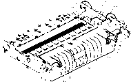
图5是供应单元的立体图;Fig. 5 is a perspective view of the supply unit;
图6A至图6E是示出供应盘和供应单元的作用的侧视图;6A to 6E are side views illustrating the function of the supply tray and the supply unit;
图7是图像记录设备的局部放大的剖视图;7 is a partially enlarged sectional view of the image recording device;
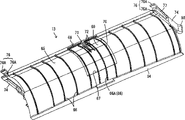
图8是外弧形引导件的后表面的立体图;Figure 8 is a perspective view of the rear surface of the outer arc guide;
图9是外弧形引导件的前方立体图;Figure 9 is a front perspective view of the outer arc guide;
图10是外弧形引导件的侧面视图;Figure 10 is a side view of the outer arc guide;
图11是示出处于其中拆卸外弧形引导件的状态中的图像记录设备的一部分的立体图;以及11 is a perspective view showing a part of the image recording apparatus in a state in which the outer arc-shaped guide is detached; and
图12是示出处于其中装上外弧形引导件的状态中的图像记录设备的一部分的立体图。Fig. 12 is a perspective view showing a part of the image recording apparatus in a state where an outer arc guide is attached.
具体实施方式Detailed ways
现在参阅图1至图10,将叙述本发明的一实施例。Referring now to Figures 1 to 10, an embodiment of the present invention will be described.
图1是按照本发明的图像记录设备1的外形的立体图;以及图2是图像记录设备1的剖视图。在以下的说明中,垂直方向是基于图2,关于前和后方向、图2的左侧是前方。1 is a perspective view of the appearance of an
本发明的图像记录设备1是多功能设备,具有传真功能、打印功能、复印功能和扫描功能。图像记录设备1具有大体上和基本上为箱形的壳体2。壳体2具有大体上的方形,它的一侧的尺寸略大于在平面图中A4规格纸的长度。壳体2为两件结构,包括基本箱形的设备本体3,和在其上安装的盖子本体4、以便复盖上表面。盖子本体4能够相对于设备本体3被打开和关闭,以及设置有用于阅读图像的阅读单元5、操作面板6等。The
设备本体3设置有朝前方敞开的、在其宽度中央的孔8。孔8的下侧对应于用于储存供应盘9的盘储存部分10,供应盘容装有在其上的堆置的片形记录介质(未示出),例如纸张或OHP片。设置在盘储存部分10之上的孔8的内侧(后侧)是用于在记录介质上形成图像的图像记录单元11。在图像记录单元11的进一步内侧上设置有外弧形引导件13和内弧形引导件14,以及在弧形引导件13、14之间形成用于连接在盘储存部分10内的供应盘9的远端和图像记录单元11的后端的U形自由通道15。设置在图像记录单元11和供应盘9之间的是用于将供应盘9上的记录介质朝图像记录单元11输送的供应单元16。图像记录设备1适合于如图2中的箭头所示由供应单元16将堆置在供应盘9上的记录介质传送到自由通道,允许记录介质通过自由通道到达图像记录单位,从而在其上记录预定的图像,以及将它排放到供应盘9的前上表面。在设备本体内,设置用于驱动供应单元16的驱动单元(未示出),和用于控制各部分的动作的控制电路(未示出)。The
现在将详细叙述各部分的结构。The structure of each part will now be described in detail.
首先参阅图3、图4等,将叙述供应盘9。图3是供应盘9的平面视图,图4是供应盘9和设置在设备本体3的侧部上的供应单元16的立体图。通过从上述盘储存部分10朝前水平拉出,从设备本体3可以取出供应盘9,以及通过从拆卸状态水平插入盘储存部分10内能够再将供应盘储存进入设备本体3。供应盘9设置有矩形底板18和被形成为具有接近在平面图中A4规格尺寸的薄板。底板18能够接纳堆置在其上表面上的记录介质,该上表面的大约后半区域对应于后堆置表面19A和大约前半区域对应于前堆置表面19B。两堆置表面19A、19B是倾斜的,以致在记录介质输送方向的下游侧是较低的,前堆置表面19B的倾斜角度大于后堆置表面19A的倾斜角度(见图2)。Referring first to Fig. 3, Fig. 4, etc., the
在后堆置表面19A的左和右侧上,在相互分开的一距离处设置一对侧端引导件20R、20L。侧端引导件20R、20L各自设置有沿着后堆置表面19A、从后堆置表面19A的后端的稍许向前的位置至后堆置表面19A的前端附近的位置的底壁部分21。具有与底壁部分21相同长度的引导壁22从相应底壁部分21的底板18的宽度方向外端、垂直于前后方向(即记录介质输送方向)延伸。直引导棒23从相应的底壁部分21的底表面朝另一侧端引导件20R、20L延伸。两直引导棒23在前后方向相互分开的预定距离处平行设置,以及被装配进入沿着相应的底板18、在侧向设置的凹槽24内。通过使底壁部分21与后堆置表面19A滑动接触和使直引导棒23沿着凹槽24滑动,侧端引导件20R、20L能够在侧向(即,与记录介质供应方向正交的方向)移动。两直引导棒23在相互相对的部分上形成有齿条25,两相应的齿条25与可转动地设置在底板18的宽度方向中央的小齿轮26啮合。以这方式,两侧端引导件20R、20L通过小齿轮26相互连接,以致相互互锁,以始终保持从两引导壁22至底板18的宽度方向中央的距离相等。当在两侧端引导件20R、20L之间的距离扩大至最大宽度(图3中的状态)时,在两引导壁22之间的距离几乎等于A4规格的较短侧(宽度)的尺寸。On the left and right sides of the
在底壁部分21之上,从两侧端引导件20R、20L的引导壁22的上端、前端附近延伸悬伸部分28。各自的悬伸部分28在后端形成有以致垂直延伸的止动部分29。这些止动部分29位于排放辊99(以后叙述)之下,以及限制排放的记录介质在悬伸部分28之上向后运动。在右侧端引导件20R的前端处设置用于将两侧端引导件20R、20L调节所需位置的位置调节件30。位置调节件30包括沿着底壁部分21、引导壁22和悬伸部分28的相应表面具有倾斜的C形的弹性条带30A,因此,在其中在弹性带30A上不施加外力的情况下,设置在下表面上的锁定凸起(未示出)啮合形成在后堆置表面19A上在侧向形成的、具有粗糙表面的肋带30B,以实现对准。通过握持设置在弹性带30A的上端上的操作槽30C,使弹性带30A弹性变形,释放在锁定凸起和肋带30B之间的啮合从而两侧端引导件20R、20L能够在侧向移动。Over the bottom wall portion 21 , an
在后堆置表面19A的宽度方向的中央,有一对对齐肋31,它们能够在直立位置至折叠位置之间运动,当对齐肋31处在直立位置中时,明信片尺寸或大照片尺寸的记录介质能够相对于设置在后堆置表面19A的后端处的引导板43定位。At the center of the width direction of the
在底板18上、在对应于前堆置表面19B的区域的两侧端处设置沿着后方向的、以致直立突起的固定的侧壁32。两固定侧壁32被设置成当在两侧端引导件20R、20L之间的距离被扩大到最大宽度时与相应的引导壁基本平齐地对齐。在固定侧壁32的上端,设置跨越两固定侧壁32延伸的盖件33,该盖件能够从上方复盖堆置在底板18上的记录介质,通过设置在其两端上的装配揿扣边34将盖件33从上方连接到相应的固定侧壁32的上端,以及从两固定的侧壁可拆卸。盖件33朝后向下倾斜,以致从整体来看大体与前堆置表面19B平行。盖件33的上表面形成有沿着后边的凸起部分35,相应侧端引导件20R、20L的悬伸部分28的前端的高度与该凸起部分的高度相同。并且,盖件33在其宽度的中央形成有朝前方敞开的缺口36。Fixed
底板18的前堆置表面19B在其宽度的中央形成有朝前敞开的矩形支持件储存槽38,在平面图中相同矩形的板形辅助支持件39安装在支持件储存槽38内。辅助支持件39能够前后方向移动,在不使用时如图2中实线所示,全部储藏在支持件储存槽38内,以及在使用时如图中双点划线所示,从支持件储存槽38朝前拉出预定长度。在辅助支持件39的前部形成侧向细长的以致在垂直方向贯穿的手指孔40,在支持件储存槽38的底表面上,在对应于手指孔40的位置也设置一第二手指孔41。The front stacking
将引导板43安装于底板18的后端的整个宽度上,引导板43在前表面处向上倾斜。当输送单元16(后面叙述)朝引导板43推动堆置在底板18上的多张记录介质时,分离一张记录介质和向上引导该记录介质的前导边。引导板43以这样一方式稍许弯曲,即宽度方向(侧向)中央部分朝前突出,连接金属分离件44,以致在其中央与该突出端重叠。分离件44包括在垂直方向以预定间距设置的多个齿,各齿的未端从引导板43的前表面稍许突出,以致当输送单元16推出的多张记录介质变成与齿的未端抵靠着时分离一张记录介质。在分离件44的宽度方向两侧上、上端处的中央突起端上设置一对可转动的供应辅助辊45。A
右侧端引导件20R设置有用于在从设备主体3拉出供应盘9或将其插入该主体时摆动供应辊52和臂件53的凸轮部分60(摆动单元)。凸轮部分60设置在侧端引导件20R的引导壁22的后上端,以致沿着前后方向变化离开底板1 8的底表面的高度,如图6A至6E所示,包括向下向后倾斜的倾斜表面60A和向上向后倾斜的倾斜表面60B,以及具有离开底板18的底表面基本等高的从前至后连续的水平部分60C。将水平部60C形成为几乎到达引导壁22的后端,以及具有与引导板43的上端相同的高度。The
随后,参阅图2和图5,将叙述记录介质的供应单元16。图5是供应单元16的立体图。Subsequently, referring to FIG. 2 and FIG. 5 , the
设备主体3在供应盘9的后上位置设置有侧向细长的箱形框架47,在框架47内设置侧向(在与记录介质输送方向正交的方向)延伸的可转动的支持轴48,从整体看由支持轴48支持供应单元16。支持轴48设置在从供应盘9的大约宽度方向中央到右端的范围内。支持轴48设置有在供应盘9的宽度方向外端处、更具体地、在比底板18的侧端稍许外侧的端部处的大齿轮49。大齿轮49连接于驱动单元(未示出),从而由驱动单元的动力转动支持轴48。支持轴48在其另一端处设置有基本相同直径的小齿轮50。The apparatus
用于支持供应辊52的臂件53安装至位于供应盘的端部的宽度方向中央处的支持轴48的端部。臂件53从支持轴48径向朝外延伸,以及设置有一对支持臂54,该对臂在侧向相互分开的距离处相互平行。供应辊52被布置在两支持臂54的远端(摆动端)之间,由设置在支持臂54上的轴承部分55支承供应辊52的转轴,从而供应辊52可转动地保持在侧向延伸轴线周围。在两支持臂54之间,设置用于连接支持轴48的小齿轮50的四只动力传动齿轮56(动力传送机构)和所结合的供应辊52的齿轮部分52A,以致被连续在支持臂54的延伸方向,从而当驱动单元转动支持轴48时,将转动力通过四只动力传动齿轮56传送到供应辊52。出自四只动力传动齿轮56的、直接与小齿轮50啮合的动力传动齿轮56A称为用于从支持轴48将转动力传送给供应辊52的、以及用于防止从供应辊52将转动力传动给支持轴48的单向齿轮。An
臂件53能够从向后向下倾斜的位置摆动到水平位置,在向后向下倾斜的位置中供应辊52的转轴处于比支持轴48较低的位置,在水平位置中供应辊52的转轴与支持轴几乎在相同高度。当臂件53处于水平位置中时,臂件53和供应辊52的主要部分被储藏在框架47内。当容装有堆置在其上的许多记录介质的供应盘安装在盘储存部分10的标准安装位置时,臂件53的摆动端依靠它自身重量向下运动,供应辊52处在记录介质的最上层上。依靠通过在图2中逆时针转动供应辊52、向后推动记录介质和该记录介质的前导边压靠于上述引导板43,分离一张记录介质和将它传送到自由通道15。将对于记录介质具有大摩擦系数的软木板57粘附在其中记录介质不放置在其上的状态下、能抵靠着供应辊52的位置处的、供应盘9的后堆置表面19A上,从而供应辊52能够易于传送堆置在供应盘9上的最后一张记录介质。The
供应单元16设置有从动部分61,在从设备主体3拉出供应盘9或将其插入该主体时,该部分在与凸轮部分60和引导板43协作摆动供应辊52和臂件53。一体地设置从动部分61,以致从位于支持轴48上的臂件53的支持臂54的下端沿着支持轴48侧向延伸,以及具有与支持臂54的下端表面基本平齐地对齐的板形。由于在其中供应盘9被安装到标准的安装位置的状态下,从动部分61位于引导壁22之上,而与侧端引导件20R的侧向位置无关。从动部分6 1的后边61A稍许向上弯曲,以及从支持轴48的中心到后边61A的距离略小于从支持轴48的中心到供应辊52的转轴的距离的一半。如后面会叙述的那样,从动部分61适合于在拉出或插入、供应盘9的下表面成为与凸轮部分60或引导板43滑动接触时在垂直方向运动,从而臂件53摆动。The
随后,参阅图7至图12,将叙述外弧形板13。图7是图像记录设备1的局部放大剖视图;图8是当从上后方倾斜地观察时外弧形引导件13的立体图;图9是当从下前方倾斜地观察时外弧形引导件13的立体图;图10是外弧形引导件13的侧视图;图11是示出图像记录设备1的一部分、在其中拆去外弧形引导件13的状态下的立体图;图12是示出图像记录设备1的一部分、在其中装上外弧形引导件的情况下的立体图。Subsequently, referring to Fig. 7 to Fig. 12, the outer arc-shaped
外弧形引导件13被安装至图像记录单元11的后方和供应盘9的后端的上方的一位置,以及能够通过壳体2的后表面上敞开的引导安装孔63连接和拆卸(以及参见图2)。整个外弧形引导件13被存放在壳体2内,外弧形引导件13的后端大体与壳体2的后表面配合。外弧形导件13设置有在宽度方向细长的和基本弧形弯曲的主体64,主体64形成有用于引导记录介质的外引导表面65,以致与自由通道15相对。外引导表面65在侧向形成在基本与供应盘9相同的范围内。外引导表面65的上游端位于引导板的上端,外引导表面65的下游端位于直接在构成图像记录单元11的记录介质插入口95(后面叙述)的对齐辊93和被动辊64的前面。外引导表面65具有靠近上游端基本垂直延伸的大体弧形,以及随着它延伸至下游逐渐向前倾斜,然后在成为水平之后,朝前向下倾斜,到达下游端。外引导表面65在下游端附近的部分是平表面。外引导表面65形成有沿着记录介质的输送方向,在宽度方向设置的预定间距处的多条凸起肋66。并且,外引导表面65在靠近下游的部分、在宽度中央部分朝自由通道15突出,因此,位于宽度中央的肋66A朝自由通道突出的尺寸比在其它位置处的肋66的突出尺寸较大。The outer arc-shaped
主体64在凸出部分的下游侧在外引导表面65的宽度中央形成有安装凹槽67,以及将弯曲板成形的阻力减少部分68连接于安装凹槽67。包括主体64和阻力减少部分68的外弧形引导件全部由合成树脂形成,阻力减少部分68由比构成其它部分的合成树脂具有对于记录介质较小摩擦阻力的合成树脂形成。更具体地阻力减少部分68由聚缩醛树脂(POM)或类似物形成,其它部分例如由聚苯乙烯树脂(PS)或类似物形成。阻力减少部分68的表面形成具有基本像主体64的外引导表面65的形状的引导表面69,以及引导表面69形成有沿着记录介质输送方向、与形成在主体64的上述凸起部分上的肋66A连续的多条凸起肋70。在阻力减少部分68上,靠近上游端的肋70的突出尺寸比在主体64的该侧上的肋66A的上端处的突出尺寸略小。因此,可以防止由于因成形误差或类似情况产生的阻力减少部分68上的肋70的下端比在主体64的该侧上的肋66A更突出所造成的记录介质的前导端被阻力减少部分68的该侧上的肋70保持住的情况。并且,阻力减少部分68的引导表面69在靠近下游端的宽度中央处形成有能够接纳对齐传感器88(后面叙述)的检测狭条90的未端的检测狭条接收孔71。检测狭条接收孔71设置有沿着记录介质输送方向细长的和具有与该孔的宽度方向两侧上的边缘处的其它肋70相同突出尺寸的检测辅助肋72。The
在主体64的两端的上端处形成前后方向延伸的侧板部分74。侧板部分74的前端位置基本与外引导表面65的下游端的位置相配合。具有朝前突出的上和下成对的啮合凸起76A的对齐啮合结构76设置在侧板部分74的前端。对齐辊93的轴颈支承部分93可以装配在对齐啮合结构76的成对的啮合凸起76A内。
相应的侧壁部分74在它的外侧表面上形成有从对齐啮合部分76的啮合凸起76A之间延伸的引导凹槽77。另方面,设备本体13在外弧形引导件13的两端处设置有一对侧壁78(见图11,在该图中,没有示出在另一侧上的侧壁78,它具有与在远侧上的侧壁基本对称的形状),以及相应的侧壁78设置有能够与引导凹槽77啮合的引导凸起79。引导凸起79和引导凹槽77具有在将外弧形引导件13安装至设备本体3时引导外弧形引导件13到达适当的安装位置的功能。除了端部之外引导凹槽77的宽度稍许大于引导凸起79的外径,缩小了该凹槽的宽度以便能够紧密地装配引导凸起。The corresponding
相应的侧板部分74设置有锁定部分80,以致从其后端突出。锁定部分80能够在侧向弯曲变形,以及它的远端朝外突出,从而通过将该远端啮合到形成在相应侧壁78上的凹槽啮合部分81,使外弧形引导件13锁定到适当的安装位置。弯曲成倾斜的C形的释放部分82在外弧形引导件13的宽度方向从相应锁定部分80的远端朝内延伸,从而该释放部分能够在相对于啮合部分81的释放啮合的方向移动锁定部分80。主体64在它的后表面上形成有一对左和右板形夹持部分83,以致向后延伸,夹持部分83被布置成它的远端相对于释放部分82的远端,相互分开预定的距离。通过同时夹住夹持部分83和释放部分82,可以安装和拆卸外弧形引导件13。The respective
在设备本体3内,在相对于外弧形引导件13的一距离处设置内弧形引导件14,相对于外弧形引导件13的表面相当于内引导表面85。内引导表面85的上游侧(后侧)形成为突出的弧形表面,该表面具有比外弧形引导件13的外引导表面65较大的曲率,以及下游侧(前侧)为基本水平面。内引导表面85的上游侧端(下端)位于外引导表面65的上游侧端的上方,一对左和右供应辅助辊86可转动地设置在它的宽度方向中央。内引导表面85设置有沿着记录介质输送方向的、在前侧和后侧上分开的、以及在宽度方向以预定间距设置的许多凸起肋。Inside the
在内弧形引导件14的内引导表面85和外弧形引导件13的外引导表面65之间形成U形自由通道15,如以上所述。弧形引导件13、14的引导表面65、85之间的距离在上游侧(自由通道15的入口侧)较大,朝下游逐渐减小。因此,在引导表面65、85之间的距离除了靠近下游端的部分之外被设定为比记录介质厚度大得较多的数值,以便在自由通道15内、在厚度方向允许记录介质移动。在靠近下游端的区域内,在引导表面65、85之间的距离、在窄的意义上、在两引导表面65、85上的肋66、67的远端位置之间的距离被设定为较小值,从而走出自由通道15的记录介质的前导边相对于由对齐辊93和被动辊94构成的记录介质插入口95被准确地对齐。以这方式,当记录介质从供应辊52输送到对齐辊93时,没有提供用于如一压辊紧密地输送记录介质的装置。A U-shaped
用于检测记录介质的前导边和尾随边的对齐传感器88设置在内弧形引导件14的下侧(在离开内引导表面85的相对表面侧上)上,宽度方向的中央。对齐传感器88设置有能够围绕在侧向延伸的安装轴89转动的检测狭条90,由弹簧件(未示出)沿图7中的顺时针方向推动检测狭条90。在内弧形引导件14上形成通孔91,检测狭条90的远端突出进入自由通道。当检测狭条90的远端不与在自由通道15内的记录介质相干涉时,它被接纳在外弧形引导件13上的检测狭条接纳孔71内(以下称为不干涉位置,见图7中的实线)。当检测狭条90的远端与记录介质干涉时,检测狭条90向下缩回(称为干涉位置,见图7中的双点划线)。对齐传感器88设置有光阻挡器(未示出),用于检测该检测传感器90的位置。An
现在参阅图2、图7和图11,将叙述图像记录单元11。对齐辊93设置在图像记录单元11的上游端(后端),以致在侧向延伸。在对齐辊93的两端设置固定于设备本体3轴颈支承部分93A。由驱动单元的动力可转动的转动部分93B设置在两轴颈支承部分93A之间。可与对齐辊93一起转动的多个被动辊94设置在对齐辊93的转动部分93B之下。在对齐辊93和多个被动辊94之间形成的是记录介质插入口95,上述自由通道15的下游端连接于记录介质插入口95。Referring now to FIGS. 2, 7 and 11, the
图像记录单元11设置有在被动辊94的下游侧(前侧)上的台板96,用于从下方支持记录介质。具有在其上安装的记录头97的滑架98设置在图像记录单元11之上,滑架98在台板96上方侧向运动,记录头97将印墨排放在台板96上的记录介质上,用于记录图像。设置在台板96的下游侧上的是在侧向延伸的排放辊99。排放辊99通过与对齐辊连接而被转动,将在其上记录头97记录了图像的记录介质排放在供应盘9上。The
这样至此已叙述了该实施例的结构。现在将叙述它的工作。Thus the structure of this embodiment has been described so far. Its working will now be described.
当使记录介质堆置在存放于设备本体3内的供应盘9上时,从盘存放部分10朝前方拉出供应盘9。此时,通过将手指钩入在支持部分储存孔38内的辅助支持部分39的手指孔40内和进入底板18上的第二手指孔41内,用于朝操作者方向拉动,能够易于拉出供应盘9。When recording media are stacked on the
当拉出处在其中事先堆置了记录介质的状态中的供应盘9时,需要从放置在其上表面上的供应辊52的下侧拉出记录介质。假设供应盘9的后堆置表面19A是水平面,当拉出供应盘9时,记录介质可能被供应辊夹住。相反,按照这实施例,由于供应盘9的后堆置表面19A在记录介质输送方向朝下游(后侧)向下倾斜,当拉出供应盘9时,记录介质离开供应辊52向下运动,因此记录介质很难被供应辊52夹住,因此能够平稳地拉出供应盘9。When pulling out the
随后,将叙述在拉出供应盘9时供应单元16的工作。当供应盘9处在适当的安装位置时,供应辊52处于抵靠着记录介质的上表面或底板18的后堆置表面19A的状态中,从动部分61处在向上离开凸轮部分60的倾斜表面60A的位置处(见图6A)。当从该状态向前拉动供应盘9时,从动部分61的后边61A变成抵靠着凸轮60的倾斜表面60B,在与倾斜表面60B的滑动接触中向上运动,因此,臂件52在该图中逆时针摆动,因此使供应辊52上升(见图6B)。当进一步拉出供应盘9时,从动部分61的后边61A在凸轮部分60的倾斜表面60B上运动,然后从动部分61在水平部分60C的上表面上逐渐移动,从而使臂件53成为大体水平姿态(见图6C)。然后,供应辊52成为抵靠着引导板43的上端,以及在引导板43上移动,同时通过对于引导板43的摩擦转动。当供应辊52越过引导板43时,引导板43的上端成为抵靠着臂件53的下表面,以及在臂件的滑动接触中朝支持轴48运动(见图6D)。然后,当引导板43的上端从臂件53的下表面向前移出时,供应辊52由它自己的重量向下运动(见图6E)。Subsequently, the operation of the
以这方式,由于在侧端引导件20R上设置用于在安装和取出供应盘9时提升供应辊52的凸轮部分60,能够省去供应盘的侧壁,从而能够缩小供应盘9的宽度,从而实现设备尺寸的缩小。In this way, since the
并且,由于供应盘9不仅设置有可移动侧端引导件20R、20L,而且在它的前方有固定侧壁32,因此用手能够易于握持它。固定侧壁32基本上与侧端引导件20R平齐地对齐,因此不增加供应盘9的宽度。Also, since the
当以这方式从设备本体3取出供应盘9时,将成为一叠的要使用的记录介质放置在堆置表面19A、19B上。当使用例如A4规格或B5规格的记录介质时,从供应盘9的前部、通过盖件33的下侧插入记录介质,到达它们抵靠着内引导板43的位置。此时,由于盖件33形成有缺口36,即使记录介质小于A4规格(例如B5规格),也能够易于插入、到达最内位置。当使用例如小于B5规格的明信片规格或大照片规格的记录介质时,使相应的对准肋31直立,将记录介质放在对准肋31和引导板43之间。When the
随后,当记录介质的两侧不与相应的引导壁22对齐时,调节两侧端导件20R、20L在侧向的位置,以便将引导壁22与记录介质的两侧端相配合。在此时,当在宽度方向移动右侧端引导件20R时,也与其一起移动左侧端引导件20L,因此实现了良好的对准工作能力。当两侧壁22与记录介质的两侧端位置对齐时,记录介质对准于供应盘9的宽度方向中央。Subsequently, when the sides of the recording medium are not aligned with the
随后,将在其上容装有堆置的记录介质的供应盘9存放在设备本体3内。当从前方水平地将供应盘9插入盘存放部分内时,引导板43的上端首先抵靠着从动部分61和臂件53,从动部分61和臂件53在引导板43上逐渐上升。那么,供应辊52上升,臂件53摆动至大体水平姿态(见图6D)。当供应盘9从这状态进一步向内插入时,从动部分61在凸轮部分60的水平部分60C上逐渐移动,随后,供应辊52抵靠着引导板43的上端和在该上端上逐渐移动(见图6C)。然后,从动部分61的后边61A沿着凸轮部分60的倾斜部分60B运动和供应辊52向下运动(见图6B)。因此,供应辊52抵靠着在堆置表面19A、19B上堆置的记录介质的上表面,以及从动部分61从凸轮表面60向上升起。在此时,由于用于记录介质的、供应盘9的后堆置表面19A朝记录介质输送方向的下游侧(后端侧)向下倾斜。记录介质被插入在供应辊52之下,以致从下向上推动供应辊52。因此,与其中记录介质的堆置表面是水平的情况比较,记录介质很难被供应辊52夹住,因此,能够防止记录介质的移位。当供应盘9被插入到适当安装位置(图6A所示的位置)时,完成了供应盘9的安装。Subsequently, the
其后,将叙述在记录介质上记录图像时的工作。首先,来自驱动单元的动力转动大齿轮49,通过动力传送齿轮56将转动传送给供应辊52。因此,当供应辊52在图7中逆时针方向转动时,堆置表面19A、19B上的记录介质被向后推和抵靠着引导板43。由于引导板43的中央部分朝前突出,被推动抵靠着引导板43的记录介质的前导端被向上引导,同时采取跟随着该中央部分是稍许较高的弯曲姿态。然后,当记录介质远端的中央部分成为抵靠着设置在引导板43的凸起端的分离部分44的齿时,分离出最上方的片材。以这方式,它被传送到位于上方的自由通道15,同时保持与设置在引导板43的上端处的分离部分的宽度方向两侧的供应辅助辊45抵靠着。Hereinafter, the operation at the time of recording an image on a recording medium will be described. First, the power from the drive unit turns the
从引导板43向上传送的记录介质的前导边成为与外弧形引导件31的外引导表面65的上游侧端部附近的部分抵靠着。在那里,在外弧形引导件31的上游侧端部分附近,在多条肋的宽度方向中央处的肋66A朝自由通道15悬伸尺寸被设定为大于其它肋的该悬伸尺寸,因此依靠引导板43采取弯曲姿态的记录介质的前导边的宽度方向中央部分成为抵靠着肋66A,以及朝后释放宽度方向两端。从而,通过在记录介质的前导边和外弧形引导件13之间的抵靠接触,防止记录介质的宽度方向中央从引导板43向上升起,以及因此能够维持在记录介质和供应辅助辊45之间的接触。The leading edge of the recording medium conveyed upward from the
以这方式,被传送进入自由通道15的记录介质的前导边主要以与外引导表面65的中央处的肋66A的滑动接触被向上引导。随后,记录介质的前导边处的中央部分成为与阻力减小部分68的肋70抵靠接触。记录介质的前导边的中央部分被朝下游引导,同时保持与阻力减小部分68的肋70滑动接触,以及宽度方向两端成为与外引导表面65上的肋66滑动接触,记录介质的前导边的姿态被逐渐变成为直的姿态,从而向前引导该前导边。In this way, the leading edge of the recording medium conveyed into the
以这方式,由于在外弧形引导件13的宽度方向中央设置了具有对记录介质的较小摩擦阻力的阻力减小部分68,因此防止记录介质在输送通道被卡住,从而平稳地向下游引导记录介质。当整个外弧形引导件由具有对记录介质较小摩擦阻力的树脂形成时,可以是其中可能很难实现成形精度,或提高成本的情况。但是,按照这实施例,通过在记录介质施加较高接触压力的中央部分采用具有较低接触阻力的树脂件,减少了对记录介质的摩擦阻力,能够避免成形精度的下降和成本的提高。In this way, since the
当记录介质的前导边抵靠着突出进入自由通道15的对齐传感器88的检测狭条90时,检测狭条90被记录介质加压和向下推动(干涉位置,见图7中的双点划线),从而检测到记录介质的前导边到达检测狭条90的位置的实际状态。在那里,由于在检测狭条接纳孔71的两侧上的该孔的边缘处设置了突出的检测辅助肋72,被检测狭条90的推力加压的记录介质由成对的检测辅助肋72,从检测狭条90的相对侧支持,因此防止记录介质朝检测接纳孔71的内部弯曲。因此,能够充分地保证在干涉位置和非干涉位置之间的检测狭条90的位移量,以及能够提高记录介质的检测精度。When the leading edge of the recording medium abuts against the
通过对于检测狭条90的抵靠位置的记录介质从自由通道15移出和到达在对准辊93和被动辊94之间的记录介质插入口95。在那里,由于外弧形引导件13的下游侧附近的外引导表面65的部分是平表面,从而记录介质的前导边被准确地引向记录介质插入口95。The recording medium passing the abutment position for the
控制对齐辊,以在对准传感器88检测到记录介质的前导端时使该辊反向转动(图7中逆时针方向),在一预定时期之后使其在常规方方转动。由于在记录介质的前导端到达在两辊93、94之间的记录介质插入口95时对齐辊93反向转动,因此它不能被插入两辊93、94之间,在那里,纠正了记录介质的倾斜。The registration rollers are controlled to rotate in the opposite direction (counterclockwise in FIG. 7) when the
然后,当对准辊93在预定的计时情况下以常规方向转动时,记录介质的前导边被夹在两辊93、94之间,以及记录介质被拉向前。在那里,在记录介质由具有较高可弯曲性的材料形成的情况下(例如薄的打印纸或OHP纸),如果记录介质的前导边被拉向前,采取沿着外弧形引导件13上的肋66、70延伸的姿态的记录介质朝内弧形引导件14移动,又采取沿着内引导表面85延伸的姿态。那么,从这状态转动对齐辊93,通过供应辅助辊86将记录介质PI传送到下游侧,以及被拉入记录介质插入口95,同时与内引导表面85上的肋87滑动接触。Then, when the
当记录介质由较低的可弯曲性能的材料(例如厚板或明信片)形成时,当记录介质的前导端被朝对齐辊93的前方拉动时,记录介质朝内弧形引导件14移动。但是,在采取沿着内引导表面85延伸的姿态之前,例如图7中P2所示,记录介质P2比上述记录介质P1移动到更靠近外弧形引导件13的位置。换句话说,由具有较小可弯曲性能的材料形成的记录介质P2比由具有较大可弯曲性能的材料形成的记录介质P1的情况采取较小曲率的姿态。那么,当对齐辊93以这状态转动时,记录介质P2被拉入记录介质插入口95,同时按照不同的情况,例如来自对齐辊93的拉力或记录介质P2在自由通道15内的可弯曲性能采取自由姿态。When the recording medium is formed of less bendable material such as thick board or postcard, the recording medium moves toward the
其中,假定采取其中记录介质在传送路径上始终呈现不变的姿态(曲率的大小)的结构,从输送单元,例如对齐辊或供应辊等对记录介质施加拉力或推力时,迫使记录介质根据记录介质的材料弯曲,从而可以对输送单元施加一负载。相反,按照这实施例,由于在外弧形引导件13和内弧形引导件14之间提供自由通道15,该通道允许记录介质在厚度方向移动,所以在记录介质的姿态方面提供了灵活性,因此能够实现平衡传送,而不使用压辊或类似零件。因此,能够简化设备结构,从而能够实现尺寸的缩小。Among them, assuming a structure in which the recording medium always exhibits a constant posture (magnitude of curvature) on the conveying path, when a pulling or pushing force is applied to the recording medium from a conveying unit such as a registration roller or a supply roller, the recording medium is forced to conform to the recording medium. The material of the medium bends so that a load can be applied to the delivery unit. On the contrary, according to this embodiment, since the
当依靠对齐辊93的转动将通过记录介质插入口95的记录介质传送到台板96上时,用记录头97在台板96上的记录介质上记录预定的图像。然后,将通过台板96的记录介质朝前方输送到排放辊99,以及被排放到供应盘9的悬伸部分28的上表面和盖件33的上表面。以这方式,由于供应盘9还用作为接爱从图像记录单元11排放的记录介质的排放盘的作用,因此整个设备具有紧凑结构。并且,由于盖件33和悬伸部分28朝后向下倾斜,防止了排放在该上表面上的记录介质掉落。When the recording medium passing through the recording
当记录比盖件33或悬伸部分28的长度较大的图像,例如A4规格时,通过向前拉出辅助支持件39,能够由辅助支持件39支持从盖件的前端悬伸出的记录介质,从而防止记录介质掉落。当不需要辅助支持件39时,它可以储藏在内部,从而防止它成为障碍物。When recording an image larger than the length of the
当排放的记录介质具有不移动到盖件33的前端上的尺寸时,通过利用盖件33上形成的缺口,从上和下夹住记录介质的端部,能够易于取出记录介质,而不要从设备本体3拉动供应盘9。When the recording medium to be discharged has a size that does not move onto the front end of the
随后,将叙述在阻塞(纸的阻塞)的情况下,相对于设备本体3安装和拆卸外弧形引导体13的步骤。为了拆卸外弧形引导件13,用手指同时分别地捏住位置在外弧形引导件13的外表面(后表面)上的左和右释放部分82和夹持部分83,朝夹持部分83加压释放部分82。从而由于使锁定部分80在宽度方向朝内弯曲,释放相对于啮合部分81的啮合,捏住和向后拉释放部分82和夹持部分83。因此,释放了相对于对齐辊93的轴颈支承部分93A的对齐啮合装置76的啮合,从这状态,通过进一步拉动外弧形引导件13,引导凸起79与引导凹槽77分离,从而能够向外部拆卸外弧形引导件13。当从设备本体3拆卸外弧形引导件13时,打开了自由通道15的一侧。由于自由通道15没有设置紧密夹持记录介质的零件,例如压辊,所以能够易于进行被阻塞的记录介质的去除工作。Subsequently, the steps of attaching and detaching the outer arc-shaped
当再将将外弧形引导件13安装至设备本体3时,用手指同时捏住左和右释放部分82和夹持部分83,将释放部分82压向夹持部分83,以及将外弧形引导件13从后方插入引导安装孔63。然后,由于引导外弧形引导件13,同时使引导凸起79与引导凹槽77啮合,从而防止外弧形引导件13倾斜。当外弧形件13接近适当安装位置时,对齐辊93的轴颈支承部分93A进入在两啮合凸起76A之间,同时使相应的对齐啮合结构76的成对的啮合凸起76A向外变形和装配在其中。然后,当从释放部分82和夹持部分83释放手指时,释放部分82恢复到原位,以及锁定部分80与啮合部分81啮合。从而将外弧形引导件13锁定在适当的安装位置。When installing the
以这方式,通过同时捏住释放部分82和夹持部分83,能够同时进行锁定部分80的啮合释放操作和外弧形引导件13的安装和拆卸操作,从此获得了良好的工作性能。In this way, by simultaneously pinching the
由于外弧形引导件13的对齐啮合结构76能够装配至对齐辊93的转轴,从而能够改进外弧形引导件13相对于对齐辊93的对齐精度。因此,能够将记录介质的前导边引导至被对齐辊93夹持的位置。Since the
如以上所述,按照本实施例,由于凸轮部分60(摆动单元)设置在侧端引导件20R上,由于在拉出和插入供应盘9时提升供应辊52,因此能够省去供应盘9的侧壁,以及相应地能够缩小供应盘9的宽度,从而实现设备尺寸的缩小。As described above, according to the present embodiment, since the cam portion 60 (swing unit) is provided on the
并且,当拉出包括堆置在其上的记录介质的供应盘时,需要从放置在其上的供应辊的下侧拉出记录介质,以及当供应盘的堆置表面是平面表面时,随着供应盘被拉出,记录介质可能被供应辊夹住。相反,对于本发明的结构,由于供应盘9的堆置表面19A是倾斜的,以致在记录介质输送方向的下游侧(后侧)较低,在拉出供应盘9时,记录介质被拉出,同时与放置它的上表面上的供应辊向下分离。因此,供应辊52很难夹住记录介质,因此能够平衡地拉出供应盘9。And, when pulling out the supply tray including the recording medium stacked thereon, it is necessary to pull out the recording medium from the underside of the supply roller placed thereon, and when the stacking surface of the supply tray is a flat surface, then As the supply tray is pulled out, the recording medium may be caught by the supply rollers. On the contrary, with the structure of the present invention, since the stacking
由于臂件53包括支持供应辊52的成对的支持臂54,以及用于将驱动力从支持轴48传送到供应辊52的动力传送齿轮56设置在两支持壁54之间,因此能够缩小臂件53的结构尺寸。Since the
由于成对的侧端引导件20R、20L通过直引导棒23和小齿轮26运动,因此获得了良好的对齐工作性能。Since the paired side end guides 20R, 20L are moved by the
由于供应盘9的最内壁由引导板43形成,因此被供应辊52推出的记录介质的前导端被引导板43向上引导和供应到图像记录单元11。Since the innermost wall of the
由于分离件44设置在引导板43的突出的中央部分,因此记录介质与分离件抵靠,因此可行地分离记录介质。Since the separating
由于供应辅助辊45设置在分离件44上,在其两侧处,因此被分离件44分离的记录介质与辊45接触,从而被平稳地输送。Since the supply
除了可移动的侧端引导件20R、20L之外,由于供应盘9在其前部分设置有固定侧壁32,易于用手持它。由于该固定的侧壁被设置成与侧端引导件平齐,因此不增加供应盘的宽度。In addition to the movable side end guides 20R, 20L, since the
由于供应盘9设置有盖33,以致供应盘9也用作为接受被排放出的记录介质的一盘的作用,因此能够缩小整个图像记录设备1的尺寸。Since the
由于盖件33在其宽度方向中央形成有缺口36,因此能够易于取出排放出的记录介质。Since the
通过拉出辅助支持件39能够防止排放出的记录介质掉落。当不需要辅助支持件39时,能够将它推入,从而防止它成为障碍物。The discharged recording medium can be prevented from falling by pulling out the
如以上所述,用于记录介质的供应盘9的堆置表面是倾斜的,以致供应方向的下游侧是较低的。As described above, the stacking surface of the
而且,臂件包括在供应辊52的两端处设置的和具有用于接纳供应辊的转轴的支承部分的一对支持臂,以及用于将驱动力从支持轴传送到供应辊的动力传送机构结合在两支持臂之间。Also, the arm member includes a pair of support arms provided at both ends of the
并且,一对侧端引导件20R、20L设置在记录介质的宽度方向的相互分开的距离处,以及包括从一侧端引导件向另一侧端引导件延伸的诸直引导棒,以便在记录介质供应方向相互分开的距离处相互相对,以及用于啮合齿条的小齿轮可转动地设置在供应盘上,在诸直引导棒之间。And, a pair of side end guides 20R, 20L are provided at a distance apart from each other in the width direction of the recording medium, and include straight guide bars extending from one side end guide to the other side end guide, so that when recording The medium supply directions are opposite to each other at a distance apart from each other, and a pinion gear for engaging the rack is rotatably arranged on the supply plate between the straight guide rods.
此外,图像记录单元11设置在设备本体内;以致在供应盘的上方,供应盘的最内壁包括引导板,该板用于向上引导由供应辊推出的记录介质的前导边。Furthermore, the
并且,该引导板在其宽度方向中央部分处相对于其余部分朝前侧突出,以及在其突出端设置有用于分离以堆置形式供应的记录介质的分离件44。And, the guide plate protrudes toward the front side at its widthwise center portion with respect to the remaining portion, and is provided at its protruding end with a
此外,可转动的供应辅助辊45设置在引导板上,在分离件的宽度方向端部处。In addition, rotatable supply
而且,供应盘9在其前部设置有在两侧端引导件之间的距离被扩大至最大宽度时与侧端引导件平齐对准的一对固定侧壁。Furthermore, the
并且,对诸固定侧壁32在其上端处提供从其延伸的盖件,用于复盖堆置在供应盘上的记录介质和能够支持从图像记录单元传送出的记录介质。Also, the fixed
此外,盖件33在其宽度方向中央形成有向前的缺口。In addition, the
而且,在供应盘的前方设置辅助支持件39,以致能够抽出。Also, an
当从设备本体3拉出包括堆置在其上的记录介质的供应盘9时,需要从放置在其上表面上的供应辊的下侧拉出记录介质,当供应盘的堆置表面是临时性水平表面时,随着拉出供应盘记录介质可能被供应辊夹住。相反,对本发明的结构,由于供应盘的堆置表面是倾斜的,以致在记录介质供应方向的下游侧(后侧)较低,在拉出供应盘时,记录介质被拉出,同时与放置在其上表面上的供应辊向下分离。因此,供应辊很难夹住记录介质,从而能够平稳地拉出记录介质。When pulling out the
由于臂件包括成对的支承臂,以及结合在两支持臂之间的用于从支持轴将驱动力传送给供应辊52的动力传送机构,因此能够缩小臂件结构尺寸。Since the arm includes a pair of support arms, and a power transmission mechanism for transmitting the driving force from the support shaft to the
由于成对的侧端引导件20R、20L通过直引导棒和小齿轮运动,因此获得了良好的对齐工作性能。Since the paired side end guides 20R, 20L are moved by the straight guide rod and the pinion, good alignment workability is obtained.
由于供应盘9的最内壁由引导板形成,被供应辊推出的记录介质的前导端由引导板向上引导。Since the innermost wall of the
由于引导板43在其突出端设置有分离件,记录介质成为与分离件抵靠着,因此可靠地分离记录介质。Since the
由于供应辅助辊45设置在分离件上,在其两侧处,由分离件分离的记录介质与供应辅助辊接触,因此平稳地输送分离的记录介质。Since the supply
由于除了可移动的侧端引导件之外,供应盘设置有在其前部的固定侧壁32,因此易于用手握持。由于固定侧壁与侧端引导件大体平齐地对齐,因此不增加供应盘的宽度。Since, in addition to the movable side end guides, the supply tray is provided with a fixed
由于供应盘9设置有盖件,从而供应盘还用作为关于接受被排放出的记录介质的一盘的作用,因此缩小了整个设备尺寸。Since the
由于盖件33在其宽度方向中央形成有缺口,因此能够易于拿出被排放的记录介质。Since the
通过拉出辅助支持件39,能够防止记录介质掉落。当不需要辅助支持件时,能够将它推入,从而防止它成为障碍物。By pulling out the
本发明不局限于在以上说明和所示的附图的基础上所叙述的实施例,以下的实施例也包括在本发明的范围内。并且,除了以下所示的那些之外,不脱离本发明的范围可以作出各种各样的修改。(1)在上述实施例中,示出了其中供应盘相对于设备本体可安装上和可拆卸下的例子。但是,还能将本发明就用于能够从设备本体拉出,但不能从设备本体拆卸的供应盘。换句话说,只要供应盘的主要部分能够从设备本体拉出,将记录介质堆放在供应盘上之后,能够再将供应盘插入设备本体,就能应用本发明。因此,能够从设备本体拉出和插入其内的供应盘不仅是能够装于设备本体和从其拆卸的供应盘,而且还是不能够被装上和拆卸的供应盘。The present invention is not limited to the embodiments described above and on the basis of the drawings shown, but the following embodiments are also included within the scope of the present invention. Also, various modifications other than those shown below can be made without departing from the scope of the present invention. (1) In the above-mentioned embodiment, the example in which the supply tray is attachable and detachable with respect to the apparatus main body was shown. However, it is also possible to apply the invention to supply trays that can be pulled out from the device body, but not detached from the device body. In other words, the present invention can be applied as long as the main part of the supply tray can be pulled out from the apparatus body, and the supply tray can be inserted into the apparatus body after recording media are stacked on the supply tray. Therefore, a supply tray that can be pulled out from and inserted into the apparatus body is not only a supply tray that can be attached to and detached from the apparatus body, but also a supply tray that cannot be attached and detached.
Claims (24)
Applications Claiming Priority (2)
| Application Number | Priority Date | Filing Date | Title |
|---|---|---|---|
| JP2004062647A JP4042061B2 (en) | 2004-03-05 | 2004-03-05 | Image recording apparatus and supply tray |
| JP2004062647 | 2004-03-05 |
Publications (2)
| Publication Number | Publication Date |
|---|---|
| CN1663809A true CN1663809A (en) | 2005-09-07 |
| CN100404272C CN100404272C (en) | 2008-07-23 |
Family
ID=34747700
Family Applications (2)
| Application Number | Title | Priority Date | Filing Date |
|---|---|---|---|
| CNB2005100531976A Expired - Fee Related CN100404272C (en) | 2004-03-05 | 2005-03-03 | Image forming equipment and supply trays |
| CNU2005200073155U Expired - Lifetime CN2900176Y (en) | 2004-03-05 | 2005-03-04 | Image forming apparatus and feeding tray |
Family Applications After (1)
| Application Number | Title | Priority Date | Filing Date |
|---|---|---|---|
| CNU2005200073155U Expired - Lifetime CN2900176Y (en) | 2004-03-05 | 2005-03-04 | Image forming apparatus and feeding tray |
Country Status (4)
| Country | Link |
|---|---|
| US (1) | US7437119B2 (en) |
| EP (1) | EP1570997B1 (en) |
| JP (1) | JP4042061B2 (en) |
| CN (2) | CN100404272C (en) |
Cited By (6)
| Publication number | Priority date | Publication date | Assignee | Title |
|---|---|---|---|---|
| CN101081665B (en) * | 2006-02-22 | 2010-05-26 | 兄弟工业株式会社 | Paper Feeder and Imaging Equipment |
| CN101234709B (en) * | 2007-01-31 | 2011-04-06 | 株式会社理光 | Paper loading device, paper transmission device and imaging device |
| CN101024452B (en) * | 2006-02-24 | 2012-04-25 | 兄弟工业株式会社 | Sheet tray device and image forming apparatus having the same |
| CN101209785B (en) * | 2006-12-26 | 2012-07-11 | 兄弟工业株式会社 | sheet feeder |
| CN105204304A (en) * | 2010-09-24 | 2015-12-30 | 富士施乐株式会社 | Image forming apparatus |
| CN107628468A (en) * | 2016-07-19 | 2018-01-26 | 佳能株式会社 | Sheet discharging apparatus and the imaging device including sheet discharging apparatus |
Families Citing this family (21)
| Publication number | Priority date | Publication date | Assignee | Title |
|---|---|---|---|---|
| JP4042061B2 (en) | 2004-03-05 | 2008-02-06 | ブラザー工業株式会社 | Image recording apparatus and supply tray |
| JP4419733B2 (en) * | 2004-07-16 | 2010-02-24 | ブラザー工業株式会社 | Image forming apparatus |
| JP2006052073A (en) * | 2004-08-13 | 2006-02-23 | Toshiba Corp | Medium supply device |
| JP2006091154A (en) * | 2004-09-21 | 2006-04-06 | Toshiba Corp | Close assist device and image forming apparatus provided with the same |
| JP4633609B2 (en) * | 2005-11-21 | 2011-02-16 | 京セラミタ株式会社 | Image forming apparatus |
| JP4265599B2 (en) | 2005-12-22 | 2009-05-20 | ブラザー工業株式会社 | Image forming apparatus |
| JP4207963B2 (en) | 2006-01-24 | 2009-01-14 | ブラザー工業株式会社 | Paper feeder |
| JP4289356B2 (en) | 2006-02-02 | 2009-07-01 | ブラザー工業株式会社 | Image forming apparatus |
| US9057556B2 (en) | 2008-01-21 | 2015-06-16 | Whirlpool Corporation | Select fill sensor system for refrigerator dispensers |
| JP4947313B2 (en) * | 2008-03-31 | 2012-06-06 | ブラザー工業株式会社 | Image recording device |
| JP5316404B2 (en) | 2009-12-29 | 2013-10-16 | ブラザー工業株式会社 | Image recording device |
| US8768235B2 (en) * | 2009-12-29 | 2014-07-01 | Brother Kogyo Kabushiki Kaisha | Double-sided image recording device having a compact form factor |
| JP2011157155A (en) | 2010-01-29 | 2011-08-18 | Brother Industries Ltd | Image recording device |
| CN102180028B (en) * | 2011-01-26 | 2013-04-03 | 合肥海闻机器人开发有限公司 | Translational device of universal printer special for acryl |
| US9278553B2 (en) * | 2012-02-28 | 2016-03-08 | Seiko Epson Corporation | Recording apparatus with medium receiving tray having recess for storing feeding unit |
| JP6299249B2 (en) * | 2014-02-10 | 2018-03-28 | 富士ゼロックス株式会社 | Image forming apparatus and insertion box |
| US9707777B1 (en) | 2016-06-28 | 2017-07-18 | Hewlett-Packard Development Company, L.P. | Edge holders |
| JP6842058B2 (en) * | 2016-11-17 | 2021-03-17 | セイコーエプソン株式会社 | Recording device |
| JP7615596B2 (en) * | 2020-10-01 | 2025-01-17 | 富士フイルムビジネスイノベーション株式会社 | Recording material processing apparatus and image forming system |
| JP7732198B2 (en) * | 2021-02-26 | 2025-09-02 | ブラザー工業株式会社 | Image recording device |
| JP2024107994A (en) * | 2023-01-30 | 2024-08-09 | 京セラドキュメントソリューションズ株式会社 | Paper post-processing device and image forming system |
Family Cites Families (29)
| Publication number | Priority date | Publication date | Assignee | Title |
|---|---|---|---|---|
| US4780740A (en) * | 1985-04-02 | 1988-10-25 | Kentek Information Systems, Inc. | Paper feeding cassette for a printing apparatus |
| US5019839A (en) * | 1986-12-25 | 1991-05-28 | Canon Kabushiki Kaisha | Recording apparatus having a movable sheet guide member |
| JP2501445Y2 (en) * | 1990-05-25 | 1996-06-19 | アルプス電気株式会社 | Printer paper feed mechanism |
| JPH058907A (en) * | 1991-07-05 | 1993-01-19 | Asahi Optical Co Ltd | Recording paper manual feed mechanism |
| JPH06144598A (en) * | 1992-11-05 | 1994-05-24 | Ricoh Co Ltd | Slidable type paper feeding cassette used as paper discharge tray in common |
| JPH0711055A (en) | 1993-06-24 | 1995-01-13 | Fuji Photo Film Co Ltd | Cellulose triacetate film and its production |
| US5596399A (en) * | 1994-09-12 | 1997-01-21 | Xerox Corporation | Compact document measuring system for electronic document imaging |
| JP3263268B2 (en) * | 1995-02-01 | 2002-03-04 | 株式会社リコー | Paper feeder |
| JPH08301461A (en) * | 1995-05-01 | 1996-11-19 | Brother Ind Ltd | Paper cassette device |
| JP3498518B2 (en) * | 1997-03-06 | 2004-02-16 | 富士ゼロックス株式会社 | Paper feeder |
| US5932313A (en) * | 1997-04-17 | 1999-08-03 | Lexmark International, Inc. | Rubber-based paper feed rollers |
| KR100224601B1 (en) * | 1997-05-13 | 1999-10-15 | 윤종용 | The automatic feeder of complex image forming apparatus |
| KR100207730B1 (en) * | 1997-07-09 | 1999-07-15 | 윤종용 | Sheet feeding device of printer |
| JP3098500B2 (en) * | 1998-11-13 | 2000-10-16 | 日本電気株式会社 | Automatic paper feeder |
| JP2001187642A (en) * | 1999-11-26 | 2001-07-10 | Kyocera Corp | Paper cassette |
| US6322065B1 (en) * | 1999-12-22 | 2001-11-27 | Hewlett-Packard Company | Hinged-arm pick mechanism |
| US6266512B1 (en) * | 1999-12-23 | 2001-07-24 | Xerox Corporation | Method of using input size determination for improvements in productivity and imaging |
| US6290409B1 (en) * | 2000-01-05 | 2001-09-18 | Hewlett-Packard Company | Media observation frame and method of using same |
| US6287032B1 (en) * | 2000-01-05 | 2001-09-11 | Hewlett-Packard Company | Media tray supporter and method of using same |
| JP2002037478A (en) * | 2000-07-21 | 2002-02-06 | Canon Inc | Paper feeder and image forming apparatus having the same |
| US6666601B1 (en) * | 2000-09-21 | 2003-12-23 | Hewlett-Packard Development Company, L.P. | Print media loader |
| JP3870104B2 (en) | 2001-02-23 | 2007-01-17 | キヤノン株式会社 | Paper feeding apparatus and recording apparatus provided with the same |
| US6651974B2 (en) * | 2001-02-23 | 2003-11-25 | Canon Kabushiki Kaisha | Sheet feed apparatus and recording apparatus equipped with sheet feed apparatus |
| JP2002249242A (en) * | 2001-02-23 | 2002-09-03 | Canon Inc | Sheet material feeding device and image forming device |
| US6581924B2 (en) * | 2001-06-13 | 2003-06-24 | Hewlett-Packard Development Co., L.P. | Roller gear over engagement protection for document feeder |
| JP2003012175A (en) * | 2001-06-28 | 2003-01-15 | Canon Inc | Paper feeder and image forming apparatus having the same |
| JP2003176042A (en) * | 2001-12-07 | 2003-06-24 | Fuji Xerox Co Ltd | Sheet supplying device, and image forming device using it |
| JP3741068B2 (en) * | 2002-03-29 | 2006-02-01 | ブラザー工業株式会社 | Paper feeding device and image forming apparatus having the same |
| JP4042061B2 (en) | 2004-03-05 | 2008-02-06 | ブラザー工業株式会社 | Image recording apparatus and supply tray |
-
2004
- 2004-03-05 JP JP2004062647A patent/JP4042061B2/en not_active Expired - Fee Related
-
2005
- 2005-03-03 CN CNB2005100531976A patent/CN100404272C/en not_active Expired - Fee Related
- 2005-03-04 EP EP05251296.9A patent/EP1570997B1/en not_active Expired - Lifetime
- 2005-03-04 US US11/071,257 patent/US7437119B2/en not_active Expired - Fee Related
- 2005-03-04 CN CNU2005200073155U patent/CN2900176Y/en not_active Expired - Lifetime
Cited By (11)
| Publication number | Priority date | Publication date | Assignee | Title |
|---|---|---|---|---|
| CN101081665B (en) * | 2006-02-22 | 2010-05-26 | 兄弟工业株式会社 | Paper Feeder and Imaging Equipment |
| CN101024452B (en) * | 2006-02-24 | 2012-04-25 | 兄弟工业株式会社 | Sheet tray device and image forming apparatus having the same |
| CN101209785B (en) * | 2006-12-26 | 2012-07-11 | 兄弟工业株式会社 | sheet feeder |
| CN101234709B (en) * | 2007-01-31 | 2011-04-06 | 株式会社理光 | Paper loading device, paper transmission device and imaging device |
| CN105204304A (en) * | 2010-09-24 | 2015-12-30 | 富士施乐株式会社 | Image forming apparatus |
| USRE46620E1 (en) | 2010-09-24 | 2017-12-05 | Fuji Xerox Co., Ltd. | Image forming apparatus including a recessed handle portion for extension portion |
| CN105204304B (en) * | 2010-09-24 | 2018-08-03 | 富士施乐株式会社 | image forming device |
| USRE47827E1 (en) | 2010-09-24 | 2020-01-28 | Fuji Xerox Co., Ltd. | Image forming apparatus including a recessed handle portion for an extension portion |
| CN107628468A (en) * | 2016-07-19 | 2018-01-26 | 佳能株式会社 | Sheet discharging apparatus and the imaging device including sheet discharging apparatus |
| CN107628468B (en) * | 2016-07-19 | 2020-03-17 | 佳能株式会社 | Sheet discharge apparatus and image forming apparatus including the same |
| US10737898B2 (en) | 2016-07-19 | 2020-08-11 | Canon Kabushiki Kaisha | Sheet discharge apparatus and image forming apparatus including the same |
Also Published As
| Publication number | Publication date |
|---|---|
| CN2900176Y (en) | 2007-05-16 |
| EP1570997A1 (en) | 2005-09-07 |
| CN100404272C (en) | 2008-07-23 |
| JP4042061B2 (en) | 2008-02-06 |
| US20050196212A1 (en) | 2005-09-08 |
| EP1570997B1 (en) | 2015-10-14 |
| US7437119B2 (en) | 2008-10-14 |
| JP2005247542A (en) | 2005-09-15 |
Similar Documents
| Publication | Publication Date | Title |
|---|---|---|
| CN1663809A (en) | Image forming equipment and supply trays | |
| JP6171904B2 (en) | Sheet conveying apparatus and image recording apparatus | |
| CN101715035B (en) | Sheet feeding device, and image recording apparatus with the sheet feeding device | |
| US7584950B2 (en) | Image forming apparatus and sheet feeding cassette | |
| CN202062816U (en) | Image recording device | |
| US9624051B2 (en) | Sheet conveying apparatus | |
| CN107010458B (en) | Transport device and image recording device | |
| US7553012B2 (en) | Image recording apparatus | |
| CN1689944A (en) | Recording medium feeder and image recording device | |
| CN101031018A (en) | Scanner | |
| JP6136821B2 (en) | Sheet conveying apparatus and image recording apparatus | |
| CN2887803Y (en) | Paper sheet feed case and image recording device | |
| CN1799968A (en) | Sheet feeder | |
| CN1923648A (en) | Sheet supplying apparatus and image recording apparatus including the same | |
| CN1760101A (en) | Paper feed unit, paper separating unit, and image forming apparatus | |
| JP4089643B2 (en) | Image recording device | |
| CN100384708C (en) | image forming equipment | |
| US11535468B2 (en) | Recording apparatus | |
| CN1840451A (en) | Paper feeding device and image recording apparatus having such a paper feeding device | |
| JP4353284B2 (en) | Paper feeding mechanism and image forming apparatus | |
| JP6070148B2 (en) | Feeding device | |
| JP5316798B2 (en) | Paper feeding device and image recording apparatus having the same | |
| CN100398333C (en) | Two-way paper picking system | |
| JP6291976B2 (en) | Sheet conveying apparatus and image recording apparatus | |
| JPH09208060A (en) | Paper feeding device |
Legal Events
| Date | Code | Title | Description |
|---|---|---|---|
| C06 | Publication | ||
| PB01 | Publication | ||
| C10 | Entry into substantive examination | ||
| SE01 | Entry into force of request for substantive examination | ||
| C14 | Grant of patent or utility model | ||
| GR01 | Patent grant | ||
| CF01 | Termination of patent right due to non-payment of annual fee |
Granted publication date: 20080723 Termination date: 20200303 |
|
| CF01 | Termination of patent right due to non-payment of annual fee |