JP4041945B2 - Head member, ink repellent treatment method and treatment apparatus - Google Patents
Head member, ink repellent treatment method and treatment apparatus Download PDFInfo
- Publication number
- JP4041945B2 JP4041945B2 JP2001586060A JP2001586060A JP4041945B2 JP 4041945 B2 JP4041945 B2 JP 4041945B2 JP 2001586060 A JP2001586060 A JP 2001586060A JP 2001586060 A JP2001586060 A JP 2001586060A JP 4041945 B2 JP4041945 B2 JP 4041945B2
- Authority
- JP
- Japan
- Prior art keywords
- ink
- ink repellent
- repellent film
- head member
- perfluorocarbon
- Prior art date
- Legal status (The legal status is an assumption and is not a legal conclusion. Google has not performed a legal analysis and makes no representation as to the accuracy of the status listed.)
- Expired - Fee Related
Links
- 239000005871 repellent Substances 0.000 title claims abstract description 241
- 238000000034 method Methods 0.000 title claims abstract description 61
- 230000002940 repellent Effects 0.000 title claims description 215
- 238000006116 polymerization reaction Methods 0.000 claims abstract description 74
- 239000000463 material Substances 0.000 claims abstract description 12
- 239000011347 resin Substances 0.000 claims abstract description 5
- 229920005989 resin Polymers 0.000 claims abstract description 5
- TXEYQDLBPFQVAA-UHFFFAOYSA-N tetrafluoromethane Chemical compound FC(F)(F)F TXEYQDLBPFQVAA-UHFFFAOYSA-N 0.000 claims description 105
- 238000002347 injection Methods 0.000 claims description 54
- 239000007924 injection Substances 0.000 claims description 54
- 230000033444 hydroxylation Effects 0.000 claims description 24
- 238000005805 hydroxylation reaction Methods 0.000 claims description 24
- 238000010894 electron beam technology Methods 0.000 claims description 15
- 239000000758 substrate Substances 0.000 claims description 13
- 229910052731 fluorine Inorganic materials 0.000 claims description 12
- 239000011737 fluorine Substances 0.000 claims description 12
- XUIMIQQOPSSXEZ-UHFFFAOYSA-N Silicon Chemical compound [Si] XUIMIQQOPSSXEZ-UHFFFAOYSA-N 0.000 claims description 10
- 229910052710 silicon Inorganic materials 0.000 claims description 10
- 239000010703 silicon Substances 0.000 claims description 10
- 239000013078 crystal Substances 0.000 claims description 9
- 125000004432 carbon atom Chemical group C* 0.000 claims description 8
- 238000009833 condensation Methods 0.000 claims description 8
- 230000005494 condensation Effects 0.000 claims description 8
- YCKRFDGAMUMZLT-UHFFFAOYSA-N Fluorine atom Chemical compound [F] YCKRFDGAMUMZLT-UHFFFAOYSA-N 0.000 claims description 6
- 229920006395 saturated elastomer Polymers 0.000 claims description 6
- 230000002265 prevention Effects 0.000 claims description 5
- 238000003825 pressing Methods 0.000 claims 1
- OKTJSMMVPCPJKN-UHFFFAOYSA-N Carbon Chemical compound [C] OKTJSMMVPCPJKN-UHFFFAOYSA-N 0.000 abstract description 3
- 229910052799 carbon Inorganic materials 0.000 abstract description 3
- 238000000151 deposition Methods 0.000 abstract description 2
- 239000010408 film Substances 0.000 description 168
- 239000007789 gas Substances 0.000 description 53
- 238000007747 plating Methods 0.000 description 17
- 125000002887 hydroxy group Chemical group [H]O* 0.000 description 11
- PXHVJJICTQNCMI-UHFFFAOYSA-N Nickel Chemical compound [Ni] PXHVJJICTQNCMI-UHFFFAOYSA-N 0.000 description 8
- 230000015572 biosynthetic process Effects 0.000 description 8
- 238000001816 cooling Methods 0.000 description 8
- 238000010586 diagram Methods 0.000 description 8
- 238000010438 heat treatment Methods 0.000 description 8
- 125000004435 hydrogen atom Chemical group [H]* 0.000 description 7
- 238000009826 distribution Methods 0.000 description 6
- XLYOFNOQVPJJNP-UHFFFAOYSA-N water Substances O XLYOFNOQVPJJNP-UHFFFAOYSA-N 0.000 description 6
- XKRFYHLGVUSROY-UHFFFAOYSA-N Argon Chemical compound [Ar] XKRFYHLGVUSROY-UHFFFAOYSA-N 0.000 description 5
- 239000007788 liquid Substances 0.000 description 5
- 239000003960 organic solvent Substances 0.000 description 5
- 229910000831 Steel Inorganic materials 0.000 description 4
- XKRFYHLGVUSROY-YPZZEJLDSA-N argon-38 Chemical compound [38Ar] XKRFYHLGVUSROY-YPZZEJLDSA-N 0.000 description 4
- 230000000052 comparative effect Effects 0.000 description 4
- 229910052759 nickel Inorganic materials 0.000 description 4
- NJPPVKZQTLUDBO-UHFFFAOYSA-N novaluron Chemical compound C1=C(Cl)C(OC(F)(F)C(OC(F)(F)F)F)=CC=C1NC(=O)NC(=O)C1=C(F)C=CC=C1F NJPPVKZQTLUDBO-UHFFFAOYSA-N 0.000 description 4
- 125000006850 spacer group Chemical group 0.000 description 4
- 239000010959 steel Substances 0.000 description 4
- 229910052786 argon Inorganic materials 0.000 description 3
- 239000002245 particle Substances 0.000 description 3
- 239000004642 Polyimide Substances 0.000 description 2
- VYPSYNLAJGMNEJ-UHFFFAOYSA-N Silicium dioxide Chemical compound O=[Si]=O VYPSYNLAJGMNEJ-UHFFFAOYSA-N 0.000 description 2
- 230000002238 attenuated effect Effects 0.000 description 2
- 239000000498 cooling water Substances 0.000 description 2
- 125000004122 cyclic group Chemical group 0.000 description 2
- 238000006073 displacement reaction Methods 0.000 description 2
- 238000005530 etching Methods 0.000 description 2
- 239000011261 inert gas Substances 0.000 description 2
- 239000012212 insulator Substances 0.000 description 2
- 230000001678 irradiating effect Effects 0.000 description 2
- 238000004519 manufacturing process Methods 0.000 description 2
- 239000000203 mixture Substances 0.000 description 2
- 229920001721 polyimide Polymers 0.000 description 2
- 239000002994 raw material Substances 0.000 description 2
- 229910052814 silicon oxide Inorganic materials 0.000 description 2
- 229910001220 stainless steel Inorganic materials 0.000 description 2
- 239000010935 stainless steel Substances 0.000 description 2
- 238000004506 ultrasonic cleaning Methods 0.000 description 2
- 101100379079 Emericella variicolor andA gene Proteins 0.000 description 1
- 229910004298 SiO 2 Inorganic materials 0.000 description 1
- 238000010521 absorption reaction Methods 0.000 description 1
- 230000002411 adverse Effects 0.000 description 1
- 238000004140 cleaning Methods 0.000 description 1
- 230000006837 decompression Effects 0.000 description 1
- 230000008021 deposition Effects 0.000 description 1
- 230000000694 effects Effects 0.000 description 1
- 230000005684 electric field Effects 0.000 description 1
- 238000009413 insulation Methods 0.000 description 1
- 238000001459 lithography Methods 0.000 description 1
- 238000005259 measurement Methods 0.000 description 1
- 239000002184 metal Substances 0.000 description 1
- 229910052751 metal Inorganic materials 0.000 description 1
- 238000007254 oxidation reaction Methods 0.000 description 1
- 230000002093 peripheral effect Effects 0.000 description 1
- 239000004033 plastic Substances 0.000 description 1
- 230000000379 polymerizing effect Effects 0.000 description 1
- 238000003672 processing method Methods 0.000 description 1
- 238000004904 shortening Methods 0.000 description 1
- 239000007921 spray Substances 0.000 description 1
- 239000010409 thin film Substances 0.000 description 1
Images


Classifications
-
- B—PERFORMING OPERATIONS; TRANSPORTING
- B41—PRINTING; LINING MACHINES; TYPEWRITERS; STAMPS
- B41J—TYPEWRITERS; SELECTIVE PRINTING MECHANISMS, i.e. MECHANISMS PRINTING OTHERWISE THAN FROM A FORME; CORRECTION OF TYPOGRAPHICAL ERRORS
- B41J2/00—Typewriters or selective printing mechanisms characterised by the printing or marking process for which they are designed
- B41J2/005—Typewriters or selective printing mechanisms characterised by the printing or marking process for which they are designed characterised by bringing liquid or particles selectively into contact with a printing material
- B41J2/01—Ink jet
- B41J2/135—Nozzles
- B41J2/16—Production of nozzles
- B41J2/1621—Manufacturing processes
- B41J2/1632—Manufacturing processes machining
-
- B—PERFORMING OPERATIONS; TRANSPORTING
- B41—PRINTING; LINING MACHINES; TYPEWRITERS; STAMPS
- B41J—TYPEWRITERS; SELECTIVE PRINTING MECHANISMS, i.e. MECHANISMS PRINTING OTHERWISE THAN FROM A FORME; CORRECTION OF TYPOGRAPHICAL ERRORS
- B41J2/00—Typewriters or selective printing mechanisms characterised by the printing or marking process for which they are designed
- B41J2/005—Typewriters or selective printing mechanisms characterised by the printing or marking process for which they are designed characterised by bringing liquid or particles selectively into contact with a printing material
- B41J2/01—Ink jet
- B41J2/135—Nozzles
- B41J2/14—Structure thereof only for on-demand ink jet heads
- B41J2/14201—Structure of print heads with piezoelectric elements
- B41J2/14274—Structure of print heads with piezoelectric elements of stacked structure type, deformed by compression/extension and disposed on a diaphragm
-
- B—PERFORMING OPERATIONS; TRANSPORTING
- B41—PRINTING; LINING MACHINES; TYPEWRITERS; STAMPS
- B41J—TYPEWRITERS; SELECTIVE PRINTING MECHANISMS, i.e. MECHANISMS PRINTING OTHERWISE THAN FROM A FORME; CORRECTION OF TYPOGRAPHICAL ERRORS
- B41J2/00—Typewriters or selective printing mechanisms characterised by the printing or marking process for which they are designed
- B41J2/005—Typewriters or selective printing mechanisms characterised by the printing or marking process for which they are designed characterised by bringing liquid or particles selectively into contact with a printing material
- B41J2/01—Ink jet
- B41J2/135—Nozzles
- B41J2/14—Structure thereof only for on-demand ink jet heads
- B41J2/1433—Structure of nozzle plates
-
- B—PERFORMING OPERATIONS; TRANSPORTING
- B41—PRINTING; LINING MACHINES; TYPEWRITERS; STAMPS
- B41J—TYPEWRITERS; SELECTIVE PRINTING MECHANISMS, i.e. MECHANISMS PRINTING OTHERWISE THAN FROM A FORME; CORRECTION OF TYPOGRAPHICAL ERRORS
- B41J2/00—Typewriters or selective printing mechanisms characterised by the printing or marking process for which they are designed
- B41J2/005—Typewriters or selective printing mechanisms characterised by the printing or marking process for which they are designed characterised by bringing liquid or particles selectively into contact with a printing material
- B41J2/01—Ink jet
- B41J2/135—Nozzles
- B41J2/16—Production of nozzles
- B41J2/1606—Coating the nozzle area or the ink chamber
-
- B—PERFORMING OPERATIONS; TRANSPORTING
- B41—PRINTING; LINING MACHINES; TYPEWRITERS; STAMPS
- B41J—TYPEWRITERS; SELECTIVE PRINTING MECHANISMS, i.e. MECHANISMS PRINTING OTHERWISE THAN FROM A FORME; CORRECTION OF TYPOGRAPHICAL ERRORS
- B41J2/00—Typewriters or selective printing mechanisms characterised by the printing or marking process for which they are designed
- B41J2/005—Typewriters or selective printing mechanisms characterised by the printing or marking process for which they are designed characterised by bringing liquid or particles selectively into contact with a printing material
- B41J2/01—Ink jet
- B41J2/135—Nozzles
- B41J2/16—Production of nozzles
- B41J2/162—Manufacturing of the nozzle plates
-
- B—PERFORMING OPERATIONS; TRANSPORTING
- B41—PRINTING; LINING MACHINES; TYPEWRITERS; STAMPS
- B41J—TYPEWRITERS; SELECTIVE PRINTING MECHANISMS, i.e. MECHANISMS PRINTING OTHERWISE THAN FROM A FORME; CORRECTION OF TYPOGRAPHICAL ERRORS
- B41J2/00—Typewriters or selective printing mechanisms characterised by the printing or marking process for which they are designed
- B41J2/005—Typewriters or selective printing mechanisms characterised by the printing or marking process for which they are designed characterised by bringing liquid or particles selectively into contact with a printing material
- B41J2/01—Ink jet
- B41J2/135—Nozzles
- B41J2/16—Production of nozzles
- B41J2/1621—Manufacturing processes
- B41J2/164—Manufacturing processes thin film formation
Abstract
Description
【0001】
【発明の属する技術分野】
本発明は、インクジェット式記録ヘッドのヘッド部材及びヘッド部材の撥インク処理方法並びに処理装置に関し、特にパーフロロカーボンと必要に応じて四フッ化炭素とを用いての重合処理によって撥インク処理するものに関する。
【0002】
さらに、本発明は、微細孔内フッ素樹脂の除去方法及び装置に関し、特にインクジェット式記録ヘッドのヘッド部材の噴射孔内のフッ素樹脂を除去する方法及び装置に関する。
【0003】
【従来の技術】
インクジェット式記録ヘッドにおいては、ヘッド部材であるノズルプレートがインクを噴射する多数の微細な噴射孔を微小間隔を隔てて形成した構造となっている。図13はインクジェット式記録ヘッドのノズルプレートの断面図である。このノズルプレート200は、インク201を噴射する噴射孔202が設けてある。噴射孔202の噴射面203からインク201が印刷面に向けて、図13(a)に示すように噴射される。
【0004】
しかし、図13(b)に示すように、ノズルプレート200の先端面(噴射面)203に付着インク204が残存することがある。このような場合、図13(b)に示したように、次に噴射されたインク205が残存している付着インク204と接触すると、付着インク204の表面張力や粘性等の影響を受けてインク205の噴射軌道が曲げられてしまう。このように、付着インク204が噴射面203に残存していると所定の箇所に印刷をすることができないため、噴射面203に付着インク204が残存しないよう処理をしておく必要がある。
【0005】
従来は、噴射面203に例えばフッ素樹脂とニッケルの共析メッキを施して噴射面203を撥インク化させ、噴射したインク201が噴射面203に残存しないようにしていた。
【0006】
しかし、図14に示すように、撥インク膜206を形成する際に、噴射孔202内にフッ素樹脂207が付着する場合がある。このようなフッ素樹脂207が付着すると、フッ素樹脂207により噴射孔202内へのインクの流入が妨げられるため、フッ素樹脂207を噴射孔202内から除去する必要があった。
【0007】
従来においては、図15及び図16に示す方法で噴射孔202内にフッ素樹脂207が残らないようにしていた。図15に示した方法は、フッ素樹脂207の付着を予防する方法であって、撥インク膜206を形成する前に、噴射孔202内にプラスチックなどの詰め部材208を充填する。このように詰め部材208を充填した後に共析メッキを行うことにより、撥インク膜206を形成する際に噴射孔202内にフッ素樹脂207が付着することを防止することができる。また、図16に示した方法は、噴射孔202内に付着したフッ素樹脂207を除去する方法であって、超音波洗浄によりフッ素樹脂207を除去するものである。すなわち、ノズルプレート200を例えば有機溶剤209中に浸して噴射孔202内に有機溶剤209を流入させる。そして、有機溶剤209の下部に配置した超音波発生源210により、有機溶剤209中に超音波211を発生させ、この超音波211により噴射孔202内に付着したフッ素樹脂207を除去させていた。
【0008】
【発明が解決しようとする課題】
しかし、従来においては以下のような問題があった。
【0009】
従来のフッ素樹脂とニッケルとの共析メッキによる撥インク化は、メッキの前後におけるノズルプレートの洗浄を行う必要があるなど、多くの時間および労力を必要とし、生産性を低下させて労力を増大させる要因となっていた。また、インク噴射孔が入り組んだ形状をしている場合には、その部分の噴射面にメッキがされない箇所が生じることがある。このようなメッキがされない箇所が噴射面203に生じると、その箇所に付着インクが残存して、インクは噴射軌道を変えてしまうため、問題となっていた。そして、共析メッキはフッ素樹脂だけでなくニッケルを含んでいるため、その分撥インク性が劣る。また、共析メッキは形成するのに時間がかかるため、作業の効率化の面から問題となっていた。さらに、共析メッキで撥インク化を行うと、コストが高いため問題となっていた。
【0010】
さらに、上記した噴射孔内のフッ素樹脂の付着を予防する方法においては、噴射孔は孔径が数十μm程度と微細であるため、詰め部材の噴射孔内への充填や噴射孔からの除去に時間や手間がかかる。また、噴射孔内に詰め部材が付着するおそれもある。
【0011】
また、超音波洗浄にてフッ素樹脂を除去する方法においても、噴射孔が微細であるため、超音波での洗浄に時間がかかっていた。また、噴射孔に流入させた有機溶剤が表面張力等で形成した撥インク膜に接触すると、撥インク膜まで除去してしまうため、問題となっていた。
【0012】
本発明は、上記問題点を解決するためになされたもので、プラズマ重合を用いて撥インク性の高い撥インク膜をヘッド部材に形成することを目的とする。
【0013】
また、本発明は、高い撥インク性を有したヘッド部材を提供することを目的とする。
【0014】
また、本発明は、ヘッド部材に低コストで撥インク膜を形成することを目的とする。
【0015】
また、本発明は、ヘッド部材に耐久性の高い撥インク膜を形成することを目的とする。
【0016】
さらに、本発明は、微細孔である噴射孔内のフッ素樹脂を周囲に影響を与えることなく除去することを目的とする。
【0017】
【課題を解決するための手段】
上記課題を解決する本発明の第1の態様は、インクを吐出する複数の噴射孔を具備するヘッド部材において、前記噴射孔の開口する表面に、当該表面上で四フッ化炭素を混合した直鎖状のパーフロロカーボンをプラズマ重合させたフッ素樹脂からなる撥インク膜を有することを特徴とするヘッド部材にある。
【0018】
かかる第1の態様では、ヘッド部材の噴射面上に撥インク性の高い撥インク膜を形成することができる。また、撥インク膜の水酸化度及び比重合度が比較的低く抑えられる。
【0019】
本発明の第2の態様は、第1の態様において、前記撥インク膜の比重合度が、0.2以下であることを特徴とするヘッド部材にある。
【0020】
かかる第2の態様では、撥インク膜に含まれるCF3の割合が比較的低くなり、重合度が高くなる。
【0021】
本発明の第3の態様は、第1又は2の態様において、前記撥インク膜の水酸化度が、0.2以下であることを特徴とするヘッド部材にある。
【0022】
かかる第3の態様では、撥インク膜の水酸化度を比較的低く抑えることにより、すなわち撥インク膜に含まれる水酸基の割合を比較的低くすることにより、撥インク性が向上する。
【0023】
本発明の第4の態様は、第1〜3の何れかの態様において、前記撥インク膜が、前記噴射孔の開口近傍のみに設けられていることを特徴とするヘッド部材にある。
【0024】
かかる第4の態様では、撥インク膜をヘッド部材の一部のみに設けるようにしたので、短時間で撥インク膜を形成することができる。
【0025】
本発明の第5の態様は、第1〜4の何れかの態様において、前記噴射孔の内面には前記撥インク膜が存在しないことを特徴とするヘッド部材にある。
【0026】
かかる第5の態様では、噴射孔内へのインクの流入が、撥インク膜によって妨げられることがなく、インク吐出特性を良好に保持することができる。
【0027】
本発明の第6の態様は、第1〜5の何れかの態様において、平板に前記噴射孔が穿設されたノズルプレートであることを特徴とするヘッド部材にある。
【0028】
かかる第6の態様では、撥インク性の高い撥インク膜を設けたノズルプレートを比較的容易に形成することができる。
【0029】
本発明の第7の態様は、第1〜5の何れかの態様において、前記噴射孔と、当該噴射孔に連通する圧力発生室の少なくとも一部が形成されていることを特徴とするヘッド部材にある。
【0030】
かかる第7の態様では、噴射孔と圧力発生室との少なくとも一部を一体的に形成しているため、製造工程を簡略化して低コスト化を図ることができる。
【0031】
本発明の第8の態様は、第1〜7の何れかの態様において、シリコン単結晶基板からなることを特徴とするヘッド部材にある。
【0032】
かかる第8の態様では、噴射孔を高精度且つ高密度に形成でき、インク吐出特性を向上することができる。
【0033】
本発明の第9の態様は、第1〜8の何れかの態様のヘッド部材と、このヘッド部材の噴射孔に連通する圧力発生室が画成される流路形成基板と、前記圧力発生室内のインクに圧力を付与する圧力付与手段とを具備することを特徴とするインクジェット式記録ヘッドにある。
【0034】
かかる第9の態様では、インクを良好に吐出することができ、印刷品質を向上したインクジェット式記録ヘッドを実現できる。
【0035】
本発明の第10の態様は、第9の態様のインクジェット式記録ヘッドを具備することを特徴とするインクジェット式記録装置にある。
【0036】
かかる第10の態様では、印刷品質を向上したインクジェット式記録ヘッドを実現できる。
【0037】
本発明の第11の態様は、インクを吐出する複数の噴射孔を具備するヘッド部材の前記噴射孔の開口する表面の撥インク処理方法であって、真空状態に保持した室内に前記ヘッド部材を配置して、この室内に撥インク膜原料であるガス状の直鎖状パーフロロカーボンと四フッ化炭素とを導入して、前記ヘッド部材の表面上に四フッ化炭素を混合した直鎖状のパーフロロカーボンをプラズマ重合させたフッ素樹脂からなる撥インク膜を成膜して撥インク処理を行うことを特徴とする撥インク処理方法にある。
【0038】
かかる第11の態様では、ヘッド部材の噴射面に撥インク性の高い撥インク膜を比較的容易に成膜することができる。
【0039】
本発明の第12の態様は、第11の態様において、前記パーフロロカーボンが、飽和構造を有することを特徴とする撥インク処理方法にある。
【0040】
かかる第12の態様では、不飽和構造のパーフロロカーボンよりも重合時に発生する未結合手の数を少なくすることができる。
【0041】
本発明の第13の態様は、第12の態様において、前記パーフロロカーボンが、炭素を少なくとも6つ以上有することを特徴とする撥インク処理方法にある。
【0042】
かかる第13の態様では、撥インク膜原料となるパーフロロカーボンの分子量を比較的大きいものとすることで、重合して形成するフッ素樹脂の分子量も大きくすることができる。
【0043】
本発明の第14の態様は、第13の態様において、前記パーフロロカーボンが、炭素を少なくとも8つ以上有することを特徴とする撥インク処理方法にある。
【0044】
かかる第14の態様では、パーフロロカーボンは常温で液体若しくは気体として存在する。また真空中では容易に気体となるため、加熱の必要がなく重合処理に際して取り扱いを容易とすることができる。
【0045】
本発明の第15の態様は、第11〜14の何れかの態様において、前記撥インク膜の成膜後、処理ガスをプラズマ化して、当該処理ガスを前記噴射孔内に流入させて当該噴射孔内の撥インク膜を除去することを特徴とする撥インク処理方法にある。
【0046】
かかる第15の態様では、処理ガスをプラズマ化してフッ素樹脂を除去するようにしたので、極めて短時間でフッ素樹脂の分解除去を行うことができる。また、このように短時間でフッ素樹脂の除去を行えるため、噴射孔の周囲に与える影響も少なくすることができる。なお、処理ガスとしては、Heガスなどの希ガスを好ましく用いることができる。
【0047】
本発明の第16の態様は、第15の態様において、前記処理ガスのプラズマ化は、大気圧またはその近傍の圧力下で行うことを特徴とする撥インク処理方法にある。
【0048】
かかる第16の態様では、処理ガスをプラズマ化するのに高価な真空装置を必要としないため、コストを安価に低減することができる。また、処理ガスのプラズマ化を行う領域を真空にするための真空引き処理をする必要がない。このため、フッ素樹脂除去の処理に要する時間を短縮化することができる。
【0049】
本発明の第17の態様は、第15又は16の態様において、前記噴射孔の一方側で吸引することにより、前記噴射孔内にガスを流入させることを特徴とする撥インク処理方法にある。
【0050】
かかる第17の態様では、処理ガスの吸引を行わせることで、処理ガスは噴射孔周辺に接触することなく噴射孔から流出する。このため、噴射孔の周囲に影響を与えることなく噴射孔内のフッ素樹脂を除去することができる。
【0051】
本発明の第18の態様は、第15〜17の何れかの態様において、前記処理ガスを、前記ノズルプレートの前記撥インク膜が形成されていない表面側から前記噴射孔内に流入させることを特徴とする撥インク処理方法にある。
【0052】
かかる第18の態様では、噴射孔の周囲に影響を与えることなく噴射孔内のフッ素樹脂を除去することができる。
【0053】
本発明の第19の態様は、第11〜14の何れかの態様において、前記撥インク膜の成膜後、前記噴射孔内に紫外線を照射して当該噴射孔内の撥インク膜を除去することを特徴とする撥インク処理方法にある。
【0054】
かかる第19の態様では、紫外線は直進性が強いため、噴射孔内の領域のみに照射させることができる。このため、噴射孔の周囲に影響を与えるおそれがない。また、紫外線は、噴射孔内で反射しても短期間に減衰するため、反射した紫外線が噴射孔の周囲に影響を及ぼすおそれがない。このような、紫外線としては、波長が380nm以下のものが望ましく、特に波長が200nm以下のものが望ましい。この場合、紫外線の散乱や吸収を低減するため、噴射孔内への紫外線の照射経路は真空状態とすることが望ましい。
【0055】
本発明の第20の態様は、第19の態様において、前記紫外線を、前記ノズルプレートの前記撥インク膜が形成されていない表面側から前記噴射孔内に照射することを特徴とする撥インク処理方法にある。
【0056】
かかる第20の態様では、噴射孔の周囲に影響を与えることなく噴射孔内のフッ素樹脂を除去することができる。
【0057】
本発明の第21の態様は、第11〜14の何れかの態様において、前記撥インク膜の成膜後、前記噴射孔内に電子線を照射して当該噴射孔内の撥インク膜を除去することを特徴とする撥インク処理方法にある。
【0058】
かかる第21の態様では、電子線が直進性に優れているとともに、取り扱いも比較的容易であるため、フッ素樹脂を精度よく除去することが可能である。また、極めて短期間でフッ素樹脂の除去を行うことができる。この場合、電子線の直進距離を増加させるために、噴射孔内への電子線の照射経路は真空状態とすることが望ましい。
【0059】
本発明の第22の態様は、第21の態様において、前記電子線を、前記ノズルプレートの前記撥インク膜が形成されていない表面側から前記噴射孔内に照射することを特徴とする撥インク処理方法にある。
【0060】
かかる第22の態様では、噴射孔の周囲に影響を与えることなく噴射孔内のフッ素樹脂を除去することができる。
【0061】
本発明の第23の態様は、ヘッド部材を配置するための室と、当該室内を真空とする真空手段と、当該室内でプラズマ放電させるための放電部と、当該室にガス状の直鎖状パーフロロカーボンを導入する供給手段と、前記室に前記直鎖状のパーフロロカーボンと共に四フッ化炭素を導入する供給源とを有し、前記ヘッド部材の表面上に四フッ化炭素を混合した直鎖状のパーフロロカーボンをプラズマ重合させたフッ素樹脂からなる撥インク膜を成膜して撥インク処理を行うことを特徴とする撥インク処理装置にある。
【0062】
かかる第23の態様では、直鎖状パーフロロカーボンは室内に導入されて、室の放電部によりプラズマ化する。また、室内に導入された四フッ化炭素がプラズマ化して、活性なフッ素ラジカルが多く生成される。そして、直鎖状パーフロロカーボンはヘッド部材の噴射面上でプラズマ重合して、フッ素樹脂からなる撥インク膜を形成することができる。また、このとき前記室は真空手段により真空状態に保持されているため、大気中に含まれる水分子などがプラズマ重合時に付着するおそれがない。このため、ヘッド部材の噴射面上に撥インク性の高い撥インク膜を形成することができる。また、共析メッキの場合に比して時間を大幅に短縮することができる。なお、気体放電を容易に発生させるためにアルゴンなどの不活性ガスを室内に導入することが好ましい。
【0063】
本発明の第24の態様は、第23の態様において、前記パーフロロカーボンは飽和構造を有することを特徴とする撥インク処理装置にある。
【0064】
かかる第24の態様では、不飽和構造のパーフロロカーボンよりも重合時に発生する未結合手の数を少なくすることができる。
【0065】
本発明の第25の態様は、第24の態様において、前記パーフロロカーボンは、炭素を少なくとも6つ以上有するものであることを特徴とする撥インク処理装置にある。
【0066】
かかる第25の態様では、撥インク膜原料となるパーフロロカーボンの分子量を比較的大きいものとすることで、重合して形成するフッ素樹脂の分子量も大きくすることができる。
【0067】
本発明の第26の態様は、第25の態様において、前記パーフロロカーボンは、炭素を少なくとも8つ以上有するものであることを特徴とする撥インク処理装置にある。
【0068】
かかる第26の態様では、パーフロロカーボンは常温で液体若しくは気体として存在する。また真空中では容易に気体となるため、加熱の必要がなく重合処理に際して取り扱いを容易とすることができる。
【0069】
本発明の第27の態様は、第23〜26の何れかの態様において、前記パーフロロカーボンの前記室内への導入経路上に結露防止ヒータを設けて前記パーフロロカーボンを加熱可能としたことを特徴とする撥インク処理装置にある。
【0070】
かかる第27の態様では、重合処理中に結露が発生して処理速度が低減するおそれがない。
【0071】
本発明の第28の態様は、第23〜27の何れかの態様において、前記室内の前記ヘッド部材の温度を一定に維持する温度維持手段を設けたことを特徴とする撥インク処理装置にある。
【0072】
かかる第28の態様では、ヘッド部材を一定温度に維持することにより、ヘッド部材上にフッ素樹脂が凝結し易くなり、ヘッド部材上に形成する撥インク膜の成膜速度を上げることができる。
【0073】
かかる本発明のヘッド部材では、その表面にプラズマ重合させたフッ素樹脂からなる撥インク膜が形成されている。すなわち、ヘッド部材の表面上には、他の材料からなる下地層は存在せず、ヘッド部材上にはフッ素樹脂からなる撥インク膜のみが直接且つ密着性よく形成されていることになる。
【0074】
このような撥インク膜は、直鎖状のパーフロロカーボンをプラズマ重合させることによって形成するのが好ましい。さらには、この直鎖状のパーフロロカーボンと四フッ化炭素とを所定室内に導入して混合後、プラズマ重合するのが好ましい。このようにすると、室内に導入された四フッ化炭素がプラズマ化して、活性なフッ素ラジカルを多く生成する。このため、パーフロロカーボン重合時に生じる未結合手にフッ素ラジカルを結合することができる。従って、形成されるフッ素樹脂からなる撥インク膜における水酸基や水素原子の割合を大幅に低減できるとともに、撥インク膜中のフッ素の割合を高めることができる。
【0075】
また、四フッ化炭素はパーフロロカーボンを重合させて分子量の大きいフッ素樹脂を形成するとともに、分子量の小さいフッ素樹脂のエッチング処理も同時に行うことができる。このため、全体として分子量の大きいフッ素樹脂からなる撥インク膜を成膜することができる。
【0076】
このため、撥インク性に優れた撥インク膜を噴射面上に成膜することができ、噴射面上に残存インクが付着する事態を防止することができる。また、撥インク膜は、上述したように未結合手にフッ素ラジカルが結合しているため、大気中においてもフッ素樹脂が酸化するおそれがない。
【0077】
本発明に用いるパーフロロカーボンは、飽和構造を有していることが好ましい。これにより、不飽和構造のパーフロロカーボンよりも重合時に発生する未結合手の数を少なくすることができる。従って、上記水酸基や水素原子と結合する割合を一層少なくすることができるとともに、それに伴って重合度を上げることができる。これにより、撥インク効率をさらに高めることができる。
【0078】
また、本発明に用いるパーフロロカーボンが、炭素を少なくとも6つ以上有することが好ましい。このように、撥インク膜原料となるパーフロロカーボンの分子量を比較的大きいものとすることで、重合して形成するフッ素樹脂の分子量も大きくすることができる。また、このように撥インク膜を分子量の大きいフッ素樹脂にて形成することができるため、これにより撥インク効率を上げることができる。さらには、パーフロロカーボンが、炭素を8つ以上有することが好ましい。このようなパーフロロカーボンは常温で液体若しくは気体として存在する。また、真空中では容易に気体となるため、加熱の必要がなく、重合処理に際して取り扱いを容易とすることができる。
【0079】
【発明の実施の形態】
以下に、本発明の実施形態について図面を用いて詳細に説明する。
【0080】
(実施形態1)
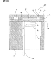
図1は、本発明の実施形態1に係るインクジェット式記録ヘッドの断面図である。
【0081】
まず、本実施形態に係るインクジェット式記録ヘッドについて説明する。本実施形態に係るインクジェット式記録ヘッド10は、縦変位型のインクジェット式記録ヘッドであり、図1に示すように、例えば、シリコン単結晶基板からなるスペーサ11には複数の圧力発生室12が並設されている。このスペーサ11の一方面側は弾性板13によって封止され、他方面側は、本実施形態のヘッド部材、すなわち、複数の噴射孔14を有するノズルプレート15によって封止されている。また、スペーサ11には、圧力発生室12にインク供給口16を介して連通するリザーバ17が形成されており、リザーバ17には、図示しないインクタンクが接続される。
【0082】
ここで、本実施形態のノズルプレートは、例えば、ステンレス鋼(SUS)からなり、孔径が約20μmの複数の噴射孔14が所定位置に穿設されている。また、これらの噴射孔14は、基本的には略直線的に形成されているが、インク導入側の端部近傍では、径が漸大するように形成されている。また、ノズルプレート15の一方面側の各噴射孔14に対応する領域には、厚さ方向の一部を除去したクレータ部18がそれぞれ設けられ、このクレータ部18によって噴射孔14の周縁部が保護されている。なお、このクレータ部18は、勿論、複数の噴射孔14に対向する領域に連続的に設けられていてもよい。
【0083】
一方、弾性板13の圧力発生室12とは反対側には、圧電素子19の先端が当接している。圧電素子19は、圧電材料20と、電極形成材料21及び22とを交互にサンドイッチ状に挟んで積層構造になるように構成され、振動に寄与しない不活性領域が固定基板23に固着されている。なお、固定基板23と、弾性板13、スペーサ11及びノズルプレート15とは、基台24を介して一体的に固定されている。
【0084】
また、本実施形態のノズルプレート15の表面上には、撥インク処理が施されている。具体的には、ノズルプレート15の表面上の各噴射孔14に対応する領域、すなわち、各クレータ部18の底面に、ノズルプレート15の表面上でプラズマ重合させたフッ素樹脂からなる撥インク膜25が形成されている。
【0085】
したがって、ノズルプレート15の表面上には、他の材料からなる下地層は存在せず、ノズルプレート15上にはフッ素樹脂からなる撥インク膜25のみが直接且つ密着性よく形成されていることになる。
【0086】
このように、ノズルプレート15の表面に撥インク膜25を設けることにより、撥インク性に優れた撥インク膜25をノズルプレート15の表面上に成膜することができ、ノズルプレート15の表面上に残存インクが付着する事態を防止することができる。したがって、インク吐出特性を常に良好に保持することができる。
【0087】
また、本実施形態では、ノズルプレート15上に下地層を設けることなく、表面上にプラズマ重合させたフッ素樹脂からなる撥インク膜25を設けているため、撥インク膜25の撥インク性を向上すると共に、密着性及び耐久性を向上することができる。
【0088】
なお、撥インク膜25の製造過程において、この撥インク膜25は噴射孔14内にも形成されるが、噴射孔14内に撥インク膜は存在しないことが好ましい。このため、本実施形態では、噴射孔14内の撥インク膜を除去している。このように、噴射孔14内に撥インク膜が存在しないようにすることにより、インク吐出特性を良好に保持することができる。この噴射孔14内に形成された撥インク膜の除去方法については、詳しく後述する。
【0089】
また、撥インク膜25は、本実施形態では、ノズルプレート15の表面上の噴射孔14に対向する領域にそれぞれ設けるようにしたが、勿論、この撥インク膜は、ノズルプレート15の全面に設けられていてもよい。
【0090】
ここで、このような撥インク膜25の形成方法について説明する。
【0091】
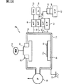
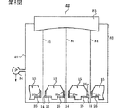
まず、撥インク膜25の形成に用いる撥インク処理装置30について説明する。撥インク処理装置30は、図2に示すように、撥インク処理を内部で行わせる室となる真空チャンバ31を有している。この真空チャンバ31は真空手段である真空ポンプ32に接続してあり、真空ポンプ32により真空チャンバ31内は133Pa(1Torr)程度の圧力に保持することができる。このように真空チャンバ31内を真空にしておくことで、大気中に含まれている水分子等を排除して撥インク処理を行うことができる。
【0092】
また、真空チャンバ31の上面には、放電部である断面凸形状の高周波電極33が挿入配置してある。高周波電極33は真空チャンバ31の外部に設けた高周波電源34に接続してあり、この高周波電源34により高周波電極33に電圧を印加させている。本実施形態においては、13.56MHz程度の高周波を用いているが、この周波数は用途に応じて変更することができる。そして、高周波電極33は、真空チャンバ31に絶縁体35を介して配置してある。このように絶縁体35を介在させたため、高周波電源34から電圧を印加される高周波電極33と真空チャンバ31との絶縁が確保できる。一方、真空チャンバ31の壁面は、アース36に接続してある。これにより、真空チャンバ31の壁面は接地を確保させることができる。このため、真空チャンバ31内に導入される四フッ化炭素37やアルゴン38に高電圧を印加してプラズマ化させることができる。
【0093】
また、真空チャンバ31床面には、温度維持手段である冷却台座39を介してノズルプレート15が配置してある。冷却台座39は内部に冷却水を流入させており、この冷却水にて冷却台座39上に配置したノズルプレート15を冷却すると共に、一定の温度に維持させている。このようにノズルプレート15を接地電極部側に配置したことで、ノズルプレート15のインク噴射面15a上に、プラズマ重合によるフッ素樹脂からなる撥インク膜25を形成することができる。本実施形態においては、冷却台座39によりノズルプレート15の表面が25℃程度となるように冷却保持している。これにより、ノズルプレート15の表面(噴射面15a)への撥インク膜25の凝結が促進される。
【0094】
なお、本実施形態では、温度維持手段としてノズルプレート15を冷却保持する冷却手段を設けるようにしたが、この冷却手段の替わりに、あるいは冷却手段に加えて、ノズルプレート15を常温よりも高い温度に維持するヒータ等の加熱手段を設けるようにしてもよい。この加熱手段を設ける場合には、ノズルプレート15の表面を比較的高い温度、例えば、約60℃程度の一定温度に維持することによって、撥インク膜25の凝結が促進され、成膜時間を短縮することができる。
【0095】
そして、真空チャンバ31内には、撥インク膜原料であるパーフロロカーボン40が流通経路41を介して導入可能となっている。本実施形態においては、パーフロロカーボン40としてC8F18を用いている。パーフロロカーボン40は供給手段となる容器42中に液体状態で配置されている。容器42下部にはヒータ43が設けてあり、このヒータ43により容器42中のパーフロロカーボン40を加熱できるようにしている。容器42は流通経路41により真空チャンバ31と接続され、大気圧よりも大幅に低い圧力に保持されている。このため、パーフロロカーボン40を大気圧の場合に比して低い温度でガス化することができる。本実施形態においては、ヒータ43によりパーフロロカーボン40を50℃程度に加熱することで、パーフロロカーボン40をガス化することができる。前記容器42の上部には、流通経路41の一端が接続されており、他端を真空チャンバ31に接続している。このため、容器42中のガス化されたパーフロロカーボン40は真空チャンバ31側の負圧により吸引され、流通経路41中を通って真空チャンバ31内に導入することができる。また、真空チャンバ31には、流通経路41と同様の流通経路44及び流通経路45が接続してあり、この流通経路44及び流通経路45はそれぞれ四フッ化炭素(CF4)37及びアルゴン(Ar)38の供給源に接続してある。そして、パーフロロカーボン40と同様に四フッ化炭素37及びアルゴン38を真空チャンバ31内に導入することができるのである。
【0096】
また、それぞれの流通経路41,44,45には流量制御弁(Mass Flow制御弁)46が設けてあり、真空チャンバ31内に流入するそれぞれのガスの流量を必要に応じて調整することができるようにしている。そして、パーフロロカーボン40の流量制御弁46には、結露防止用ヒータ47が設けてある。これにより、パーフロロカーボン40が真空チャンバ31内で結露する事を防止することができる。本実施形態においては、結露防止用ヒータ47は流通経路41を80℃程度の温度に加熱している。
【0097】
このように構成した撥インク処理装置30の作用は以下のようになる。容器42中のパーフロロカーボン40はヒータ43により50℃程度に加熱される。上述したように容器42は真空チャンバ31に接続されて負圧となるため、パーフロロカーボン40は50℃程度の加熱で容易にガス化させることができる。本実施形態においては、パーフロロカーボンとして用いたC8F18は炭素を8つ以上有しているため、常温で液体若しくは気体として存在する。また真空中では容易に気体となるため、加熱の必要がなく重合処理に際して取り扱いを容易とすることができる。このとき、パーフロロカーボン40は、結露防止用ヒータ47により結露を防止できる80℃程度の温度に加熱されて、真空チャンバ31内に導入される。そして、パーフロロカーボン40に加えて、四フッ化炭素37、アルゴン38がそれぞれ真空チャンバ31内に導入される。
【0098】
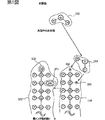
図3は、本実施形態におけるプラズマ重合を示した工程図である。上述したように、真空チャンバ31内には、高周波電圧が印加されているため、真空チャンバ31内に導入されたパーフロロカーボン40や四フッ化炭素37、アルゴン38はプラズマ化され、アルゴンラジカルやフッ素ラジカル48などのプラズマ粒子が発生する。このようなプラズマ粒子がパーフロロカーボン40の結合の弱い部分を切断して、重合反応させるのである。
【0099】
すなわち、図3に示したように、パーフロロカーボン40は、プラズマ粒子により重合反応が発生して、フッ素樹脂49を形成する。本実施形態においては、パーフロロカーボン40として用いたC8F18は炭素を6つ以上有しているため、重合する際に形成されるフッ素樹脂49の分子量も大きくすることができる。
【0100】
また、図3に示したように重合の際に結合相手のいない未結合手50が発生するが、C8F18は直鎖状かつ飽和構造であるため、環状のものや不飽和構造のものに比べて重合する際に発生する未結合手の割合を少なくすることができる。このように、真空中でプラズマ重合を行うことにより、大気中の水酸基や水素原子により重合反応が遮断されるおそれもないため、分子量の大きいフッ素樹脂49を形成することができる。また、パーフロロカーボン40として直鎖状のパーフロロカーボンC8F18を用いているため、直鎖状のフッ素樹脂49を形成することができる。
【0101】
また、このとき四フッ化炭素37は、解離して、例えば図3に示したような活性な遊離基51とフッ素ラジカル48となっている。このフッ素ラジカル48が未結合手50に結合することにより、形成したフッ素樹脂52のフッ素含有率を向上するとともに、水酸基や水素原子の含有率を低減することができる。さらに、フッ素樹脂52の酸化反応を防止することができる。これにより、形成したフッ素樹脂52の撥インク性を高めることができる。また、四フッ化炭素37はパーフロロカーボン40を重合させて分子量の大きいフッ素樹脂52を形成するとともに、分子量の小さいフッ素樹脂のエッチング処理も同時に行うことができる。このため、全体として分子量の大きいフッ素樹脂52を成膜することができる。このため、撥インク性に優れたフッ素樹脂からなる撥インク膜25をノズルプレート15の噴射面15a上に成膜することができ、噴射面15a上に残存インクが付着する事態を防止することができる。
【0102】
図4は、成膜した撥インク膜の性能の良否を示す説明図である。図4の縦軸には、形成した撥インク膜全体に含まれる水酸基の割合(以下、「水酸化度」という)を示している。そして、図4の横軸には、重合度の逆数(以下、「比重合度」という)を示している。本願発明者は、撥インク膜の撥インク性能が上記した水酸化度と比重合度に関係するとの知見を得た。すなわち、撥インク膜に水酸基が含まれているとその分だけ撥インク性が低下する。このため、水酸基の割合が少ないほど、すなわち縦軸に示した水酸化度の値が小さいほど撥インク膜の性質がよいことを示すことになるのである。一方、比重合度は、フッ素樹脂全体の中に含まれるCF3の割合で求めることができる。形成されるフッ素樹脂の終端部にはCF3基が結合するからである。上記したように、形成したフッ素樹脂の分子量が大きいほど、撥インク膜の性質がよい。すなわち、横軸の比重合度の値が小さいほど撥インク膜の性質がよいことになる。従って、原点に近い値をとるほど、撥インク膜としては性質がよいのである。図5を用いて本実施形態において形成した撥インク膜の性質について、以下に各実施例及び比較例を示して説明する。
【0103】
(比較例1)
図4のAに示した場合について述べる。Aは、フッ素樹脂とニッケルとを共析メッキして鋼(SUS)からなるノズルプレートの噴射面上に形成した撥インク膜である。この撥インク膜Aの形成時間は120分であり、300Wの電力を印加している。この撥インク膜Aの膜厚は2μmである。このような撥インク膜Aは、図4に示したように、水酸化度約0.025であるとともに、比重合度約0.06となった。
【0104】
(比較例2)
図4のBに示した場合について述べる。Bは、環状のパーフロロカーボンC4F8を大気中でプラズマ重合して鋼(SUS)からなるノズルプレートの上に形成した撥インク膜である。この撥インク膜Bの形成時間は20分であり、500Wの電力を印加している。この撥インク膜Bの膜厚は0.04μmである。このとき、四フッ化炭素は導入していない。このような撥インク膜Bは、図4に示したように、水酸化度約0.115であるとともに、比重合度約0.27となった。
【0105】
このように、BはAに比べて水酸化度、比重合度ともに大きく増大し、撥インク性において大きく劣っているが、本願発明者はこの点について以下のような知見を得た。図5は、大気中におけるプラズマ重合によるフッ素樹脂形成の問題点を示した説明図である。環状のパーフロロカーボンを重合させて形成したフッ素樹脂149には、図5に示したように結合相手のいない未結合手150が発生する。このような未結合手150に大気中の水分子153が接触すると、水分子153の水酸基154や水素原子155が未結合手150と結合してしまう。このため、形成したフッ素樹脂152は水酸基154や水素原子155を多量に含み、これにより撥インク性が著しく低下していると考えられる。また、このようなフッ素樹脂152は空気等に触れると酸化され、これにより撥インク性が低下すると考えられる。また、このような水酸基154や水素原子155が前記未結合手150と結合することで、重合反応が阻害され、そして停止する場合もある。このため、形成されるフッ素樹脂152の分子量に大きなバラツキが生じ、これも膜質を悪くする原因となっていると考えられる。
【0106】
(実施例1)
図4のCに示した場合について述べる。Cは、直鎖状のパーフロロカーボンC8F18を真空中でプラズマ重合して鋼(SUS)からなるノズルプレートの表面上に形成した撥インク膜である。この撥インク膜Cの形成時間は20分であり、200Wの電力を印加している。この撥インク膜Cの膜厚は0.1μmである。このとき、四フッ化炭素は導入していない。このような撥インク膜Cは、図4に示したように、水酸化度約0.025であるとともに、比重合度約0.18となった。
【0107】
このCはBに比べて比重合度、水酸化度ともに大きく減少させることができ、撥インク性において性能を向上できている。また、Aに比べても水酸化度の値においてはほぼ同等となっている。
【0108】
(実施例2)
図4のDに示した場合について述べる。Dは、直鎖状のパーフロロカーボンC8F18を真空中でプラズマ重合してノズルプレートの表面上に形成した撥インク膜である。この撥インク膜Dの形成時間は20分であり、300Wの電力を印加している。このプラズマ重合の際には、四フッ化炭素を導入している。ノズルプレートの材質はポリイミドであり、撥インク膜の膜厚は0.04μmである。また、Dは、パーフロロカーボンC8F18をプラズマ重合する室と別な処理室にノズルプレートを設けて、当該処理室にプラズマを導いてノズルプレートの表面上に撥インク膜を形成している。このような撥インク膜Dは、図4に示したように、水酸化度約0.035であるとともに、比重合度約0.06となった。
【0109】
このDはBに比べて比重合度、水酸化度ともに大きく減少させることができ、撥インク性において性能を向上できている。また、Aに比べても水酸化度、比重合度の値において、ともにほぼ同等とすることができ、撥インク性においてほぼ同等とすることができている。
【0110】
(実施例3)
図4のEに示した場合について述べる。Eは、直鎖状のパーフロロカーボンC8F18を真空中でプラズマ重合してノズルプレートの表面上に形成した撥インク膜である。この撥インク膜Eの形成時間は10分であり、350Wの電力を印加している。このプラズマ重合の際には、四フッ化炭素を導入している。ノズルプレートの材質は鋼(SUS)であり、350Wの電力を印加している。この撥インク膜Eの膜厚は0.03μmである。また、Eは、実施形態で示したようにプラズマ放電させる電極の一方にノズルプレートを配置して、このノズルプレートの表面上で直接フッ素樹脂を形成して撥インク膜としたものである。このような撥インク膜Eは、図4に示したように、水酸化度約0.015であるとともに、比重合度約0.06となった。
【0111】
このEはBに比べて比重合度、水酸化度ともに大きく減少させることができ、撥インク性において性能を向上できている。また、Aに比べても水酸化度、比重合度の値において、ともにほぼ同等かそれ以上とすることができ、撥インク性においてほぼ同等かそれ以上とすることができている。
【0112】
(実施例4)
図4のFに示した場合について述べる。Fは、直鎖状のパーフロロカーボンC8F18を真空中でプラズマ重合してノズルプレートの表面上に形成した撥インク膜である。この撥インク膜Fの形成時間は10分であり、400Wの電力を印加している。この撥インク膜Fの膜厚は0.02μmである。このプラズマ重合の際には、四フッ化炭素を導入している。ノズルプレートの材質はポリイミドであり、撥インク膜の膜厚は0.02μmである。また、Fは、実施形態で示したようにプラズマ放電させる電極の一方にノズルプレートを配置して、このノズルプレートの表面上で直接フッ素樹脂を形成して撥インク膜としたものである。このような撥インク膜Fは、図4に示したように、水酸化度約0.015であるとともに、比重合度約0.05となった。
【0113】
このFはBに比べて比重合度、水酸化度ともに大きく減少させることができ、撥インク性において性能が向上している。また、Aに比べても水酸化度、比重合度の値において、ともに値を低減することができ、撥インク性において共析メッキの場合よりも性能が向上することができた。
【0114】
以上のように、C〜Fに示した撥インク膜は、水酸化度が、0.2以下の範囲に抑えられ、比重合度も、0.2以下の範囲に抑えられおり、このように撥インク膜の水酸化度及び比重合度を比較的低く抑えることにより、撥インク膜の撥インク性を向上することができることが分かる。
【0115】
また、C〜Fに示した撥インク膜は、共析メッキで問題となっていたようなノズルプレートの洗浄を行う必要もなく、そのための時間や労力を大きく短縮できる。また、インク噴射孔の形状が入り組んでいても噴射面に撥インク膜を形成することができる。そして、共析メッキの場合よりコストを10分の1程度に低減させることができる。また、撥インク膜の耐久性を向上させることができる。
【0116】
なお、上述のようにプラズマ重合で撥インク膜25を形成すると、ノズルプレート15の噴射孔14内に撥インク膜25aが形成される場合があるが、この噴射孔14内の撥インク膜25aは除去することが好ましい。
【0117】
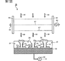
以下、この噴射孔14中の撥インク膜25aの除去方法について説明する。なお、図6は、噴射孔内フッ素樹脂除去装置60を示す説明図である。
【0118】
本実施形態の噴射孔内フッ素樹脂除去装置60では、吸引部であるプレート状の真空吸引板61上に、ノズルプレート15を配置してある。真空吸引板61は、上面部を金属からなる多孔板形状に形成している。これにより、真空吸引板61を介してノズルプレート15の噴射孔14内のガスを流通することが可能となっている。そして、真空吸引板61の下部には吸引手段である真空ポンプ62が接続してあり、この真空ポンプ62により真空吸引板61内のガスを吸引することができるようにしている。
【0119】
そして、ノズルプレート15の上方には、高周波電極部63が設けてある。この高周波電極部63は、高周波電源64に電気的に接続している。本実施形態においては、高周波電源64は、13.56MHz程度の高周波電力を高周波電極部63に印加する。
【0120】
本実施形態においては、真空吸引板61は外形が直方体形状の箱体形状をなし、この箱体形状の下面側にてアース65に電気的に接続してある。このように、真空吸引板61は接地電極部66としての機能を有している。これにより、高周波電極部63と接地電極部66間において、気体放電67を発生させることができるようになっている。このように、高周波電源64と高周波電極部63、そして接地電極部66は、プラズマ発生手段となっている。
【0121】
また、高周波電極部63と接地電極部66との間には、図示しない供給源から処理ガス68が供給されるようにしている。本実施形態においては、処理ガス68としてHeガスを用いている。この処理ガス68としては、気体放電を容易に発生させ得る不活性ガスを好ましく用いることができる。
【0122】
このように構成した装置において、噴射孔14内のフッ素樹脂からなる撥インク膜25aは以下のように除去することができる。すなわち、高周波電極部63と接地電極部66との間に処理ガス68を導入する。処理ガス68は、図6に示したように発生した気体放電67によりプラズマ化する。本実施形態においては、処理ガス68を大気圧下でプラズマ化している。このため、処理ガス68をプラズマ化するのに高価な真空装置を必要としないため、コストを安価に低減することができる。また、処理ガス68のプラズマ化を行う領域を真空にするための真空引き処理をする必要がない。このため、撥インク膜25a除去の処理に要する時間を短縮化することができる。
【0123】
上述したように、接地電極部66の上には、ノズルプレート15を配置してある。このため、ノズルプレート15の噴射孔14内に付着している撥インク膜25aは、気体放電67の経路上にあるため、プラズマ化した処理ガス68aにより分解され、噴射孔14から除去することができる。すなわち、撥インク膜25aは、活性化した処理ガスにより結合がCF3、CF2等に切断される。結合が切断された部分(CF3、CF2)は撥インク膜25aから遊離し、これにより噴射孔14から除去することができる。また、上述したように、ノズルプレート15は、噴射面15aに形成した撥インク膜25が接地電極部66側に対向するように配置している。このため、プラズマ化した処理ガス68aが撥インク膜25に直接当たることがない。
【0124】
そして、上述したように接地電極部66は、真空吸引板61と一体的に形成してある。このため、プラズマ化した処理ガス68aを直ちに噴射孔14内に流入して撥インク膜25aの分解処理を行うことができるとともに、分解処理を行った処理ガス68aを噴射孔14内から排出することができる。ゆえに、噴射孔14の周囲に形成した撥インク膜25は、処理ガスにより除去されるおそれがない。従って、噴射孔14の周囲に悪影響を及ぼすことなく、噴射孔14内の撥インク膜25aを除去することができる。また、噴射孔14内には、プラズマ化した処理ガス68aを真空ポンプ62により真空吸引板61から連続的に吸引することができるため、極めて短時間に撥インク膜25aを分解して噴射孔14内から除去することができる。本実施形態においては、膜厚0.2μm程度の撥インク膜25を形成した場合に、およそ8秒程度で噴射孔14内の撥インク膜25aの分解を行うことができる。これにより処理ガス68をプラズマ化するのに高価な真空装置を必要としないため、コストを安価に低減することができる。また、処理ガス68のプラズマ化を行う領域を真空にするための真空引き処理をする必要がない。このため、フッ素樹脂除去の処理に要する時間を短縮化することができる。
【0125】
なお、本実施形態では、噴射孔内フッ素樹脂除去装置60が、撥インク処理装置30とは別装置となっているが、勿論、これらは一体的な装置とすることもできる。
【0126】
また、噴射孔14内の撥インク膜(フッ素樹脂)除去方法は、上述した方法に限定されず、以下に説明する実施形態2〜4の除去方法を用いることもできる。なお、以下の実施形態2〜4において、実施形態1と同一の部材については同じ名称を付してその説明を一部省略する。
【0127】
(実施形態2)
図7は、実施形態2の噴射孔内フッ素樹脂除去装置70を示す説明図である。ノズルプレート15は真空吸引板61の上に配置されている。本実施形態においては、ノズルプレート15の上方にプラズマ発生手段を設けてある。すなわち、図7に示したように、ノズルプレート15の左上側に、アース65に接続した接地電極部66が配置してある。そして、ノズルプレートの右上側に、高周波電源64に接続した高周波電極部63が配置してある。高周波電極部63と接地電極部66とは、ノズルプレート15の上方で対向するように配置してある。これにより、高周波電極部63と接地電極部66との間で気体放電67を発生することができるようにしている。そして、図7に示したように、上方から処理ガス68が図示しない供給手段により供給され、気体放電67によりプラズマ化される。このプラズマ化された処理ガス68がノズルプレート15の噴射孔14内に流入して撥インク膜25aの除去を行うことができる。そして、撥インク膜25aを分解した処理ガス68は、真空吸引板61を介して真空ポンプ62により吸引される。このようにすることで、処理ガス68の撥インク膜25への影響を防止することができる。
【0128】
(実施形態3)
図8は、実施形態3の噴射孔内フッ素樹脂除去装置80を示す説明図である。本実施形態においては、紫外線81により噴射孔14のフッ素樹脂25aを除去する場合について示している。図8に示したように、本実施形態においては、ノズルプレート15を配置するチャンバ82が設けてある。チャンバ82の上部には、紫外線照射手段である紫外線照射ランプ83が設けてあり、紫外線照射ランプ83から紫外線81を下方に向けて照射することができる。チャンバ82内の下部には、ノズルプレート15が図8に示したように配置してある。また、本実施形態においては、チャンバ82に減圧手段である真空ポンプ84を接続してあり、真空ポンプ84によりチャンバ82内を真空近くの圧力に保持させている。これにより、チャンバ82内の紫外線照射ランプ83から下方に照射された紫外線81は、大きく拡散したり散乱することなく噴射孔14内の撥インク膜25aを照射することができる。噴射孔14内の撥インク膜25aは紫外線81により分解されるため、紫外線81を照射することで撥インク膜25aを噴射孔14内から除去することができる。また、紫外線81は、反射すると直ちに減衰する性質を有している。このため、撥インク膜25aに入射した紫外線81が反射して噴射面15aの撥インク膜25に入射するといった事態を防止することができる。このため、噴射孔14の周囲の撥インク膜25に影響を及ぼすことなく、噴射孔14内の撥インク膜25aの除去を行うことができる。このような紫外線としては、波長が380nm以下のものを好ましく用いることができ、特に波長が200nm以下のものを好ましく用いることができる。また、膜厚0.2μmの撥インク膜25を形成した場合に紫外線81で噴射孔14内の撥インク膜25aの除去を行う場合には、処理時間として10分から30分程度の時間がかかる。
【0129】
(実施形態4)
図9は、実施形態4の噴射孔内フッ素樹脂除去装置90を示す説明図である。本実施形態においては、電子線91により噴射孔14内の撥インク膜25aを除去する場合について示している。図9に示したように、チャンバ82の上部には、電子線照射手段である電子銃92が設けてあり、この電子銃92によりチャンバ82内下方に向けて電子線91を照射することができるようにしている。また、電子銃92はチャンバ82に支持されており、電子線91を下方に向けて照射することができる。そして、電子線91は図示しないコイルにより発生した磁場により、任意に電子線91の方向を変えることができる。チャンバ82内下部には、ノズルプレート15が配置してある。そして、チャンバ82には、真空ポンプ84が接続してあり、真空ポンプ84によりチャンバ82内を真空状態に保持できるようになっている。これにより、電子線91の平均自由行程を伸ばすことができるとともに、散乱によるエネルギー損失を避けることができる。電子線91は、直進性に極めて優れているとともに、電界を印加することにより電子線91の方向や量を容易に調整することができる。このため、噴射孔14の周囲に影響を与えることなく短時間に噴射孔14内の撥インク膜25aを除去することができる。本実施形態においては、膜厚0.2μm程度の撥インク膜25を形成した場合に、約10秒程度の短時間で噴射孔14内の撥インク膜25aを除去することができる。
【0130】
なお、実施形態1〜4で説明した噴射孔内の撥インク膜の除去方法及び除去装置は、ノズルプレート以外のものであっても、比較的内径の小さい微細孔内のフッ素樹脂を除去する場合には、好適に用いることができる。
【0131】
(実施形態5)
図10は、実施形態5に係るノズルプレートの概略を示す斜視図及び断面図である。
【0132】
本実施形態は、シリコン単結晶基板でノズルプレートを形成した例である。図10に示すように、本実施形態のノズルプレート160には、それぞれ段状断面を有する複数の噴射孔14Aが設けられている。すなわち、インク吐出方向の前側には、円形の小断面ノズル部分161(小断面側の部分)が形成され、後側には円形の大断面ノズル部分162(大断面側の部分)が形成されており、これらの境界部分は環状の断面163となっている。したがって、噴射孔14Aの軸方向に沿って切断した断面形状は先端側に向けて断面が階段状に小さくなっている。また、噴射孔14Aの先端開口は、ノズルプレート160の表面に設けられたクレータ部18の底面に開口している。
【0133】
また、このような本実施形態のノズルプレート160の噴射面には、各噴射孔14Aに対応する領域に、この噴射面上でプラズマ重合させたフッ素樹脂からなる撥インク膜25が形成されている。なお、図示しないが、実際にはシリコン単結晶基板からなるノズルプレート160上には、表面が酸化することにより酸化シリコン(SiO2)層が形成されるため、撥インク膜25は、この酸化シリコン層上に設けられることになる。
【0134】
このように、シリコン単結晶基板からなるノズルプレート160の噴射面に、この噴射面上でプラズマ重合させて撥インク膜25を設けた場合であっても、撥インク性の比較的高い撥インク膜とすることができる。
【0135】
ここで、本実施形態のノズルプレート160、すなわち、シリコン単結晶基板からなり、表面上にプラズマ重合させたフッ素樹脂からなる撥インク膜を有するノズルプレート(シリコンノズルプレート)と、上述した比較例1の共析メッキによって撥インク膜を設けたノズルプレート(SUSノズルプレート)とのそれぞれの撥インク膜25上に、図11に示すように、水及びインク滴165を注射器166で滴下し、その接触角θを調べた。その結果を下記表1に示す。なお、接触角θの測定に用いた測定装置は、Contact Angle System OCA(共和界面科学株式会社製)である。
【0136】
【表1】

表1の結果からも明らかなように、ノズルプレートをシリコン単結晶基板で形成した場合であっても、プラズマ重合させたフッ素樹脂からなる撥インク膜を設けることにより、共析メッキの場合と同等の撥インク性を有する撥インク膜とすることができる。
【0138】
(他の実施形態)
以上、本発明について説明したが、本発明は上述の実施形態に限定されるものではない。
【0139】
例えば、上述した実施形態では、ヘッド部材としてステンレス鋼あるいはシリコン単結晶基板からなるノズルプレートを例示したが、ヘッド部材としては、ノズルプレートに限定されず、例えば、噴射孔と共に、圧力発生室の少なくとも一部が一体的に形成されたヘッド部材であってもよい。
【0140】
また、例えば、上述の実施形態では、縦振動型のインクジェット式記録ヘッドを例示して説明したが、これに限定されず、例えば、成膜及びリソグラフィプロセスを応用して製造される薄膜型の圧電素子、又はグリーンシートを貼付する等の方法により形成される厚膜型の圧電素子等のたわみ変位型の圧電素子を有するインクジェット式記録ヘッド、あるいは静電振動式のインクジェット式記録ヘッド等にも適用することができる。
【0141】
さらに、上述した圧電振動式のものに限定されず、例えば、バブル方式のインクジェットヘッド等、種々の構造のインクジェット式記録ヘッドに応用することができることはいうまでもない。
【0142】
このように、本発明は、その趣旨に反しない限り、種々の構造のインクジェット式記録ヘッドに応用することができる。
【0143】
なお、上述した各実施形態のインクジェット式記録ヘッドは、インクカートリッジ等と連通するインク流路を具備する記録ヘッドユニットの一部を構成して、インクジェット式記録装置に搭載される。図12は、そのインクジェット式記録装置の一例を示す概略図である。
【0144】
図12に示すように、インクジェット式記録ヘッドを有する記録ヘッドユニット1A及び1Bは、インク供給手段を構成するカートリッジ2A及び2Bが着脱可能に設けられ、この記録ヘッドユニット1A及び1Bを搭載したキャリッジ3は、装置本体4に取り付けられたキャリッジ軸5に軸方向移動自在に設けられている。この記録ヘッドユニット1A及び1Bは、例えば、それぞれブラックインク組成物及びカラーインク組成物を吐出するものとしている。
【0145】
そして、駆動モータ6の駆動力が図示しない複数の歯車およびタイミングベルト7を介してキャリッジ3に伝達されることで、記録ヘッドユニット1A及び1Bを搭載したキャリッジ3はキャリッジ軸5に沿って移動される。一方、装置本体4にはキャリッジ軸5に沿ってプラテン8が設けられており、図示しない給紙ローラなどにより給紙された紙等の記録媒体である記録シートSがプラテン8に巻き掛けられて搬送されるようになっている。
【0146】
【発明の効果】
以上説明したように、本発明においては、真空状態に保持された室内でプラズマ重合させているため、大気中に含まれる水分子などがプラズマ重合時に付着するおそれがない。このため、撥インク性の高いフッ素樹脂を形成することができる。このようにプラズマ重合で撥インク膜を形成することにより、共析メッキの場合に比して時間を大幅に短縮することができる。そして、共析メッキの場合よりコストを大幅に低減させることができる。また、撥インク膜の耐久性を向上させることができる。
【0147】
また、本発明においては、噴射孔等の微細孔内のフッ素樹脂の分解除去を短時間で行うことができる。また、このように短時間でフッ素樹脂の除去を行えるため、微細孔の周囲に与える影響も少なくすることができる。
【図面の簡単な説明】
【図1】 図1は、本発明の実施形態1に係るインクジェット式記録ヘッドの概略を示す断面図である。
【図2】 図2は、本発明の実施形態1に係る撥インク処理装置の概略断面図である。
【図3】 図3は、本発明の実施形態1におけるプラズマ重合を示した工程図である。
【図4】 図4は、撥インク膜の撥インク性能を示す説明図である。
【図5】 図5は、大気中のプラズマ重合の問題点を示す説明図である。
【図6】 図6は、本発明の実施形態1に係る微細孔内フッ素樹脂除去装置を示す説明図である。
【図7】 図7は、本発明の実施形態2に係る微細孔内フッ素樹脂除去装置を示す説明図である。
【図8】 図8は、本発明の実施形態3に係る微細孔内フッ素樹脂除去装置を示す説明図である。
【図9】 図9は、本発明の実施形態4に係る微細孔内フッ素樹脂除去装置を示す説明図である。
【図10】 図10は、本発明の実施形態5に係るノズルプレートの概略を示す斜視図及び断面図である。
【図11】 図11は、接触角の測定方法を説明する概略図である。
【図12】 図12は、本発明の一実施形態に係るインクジェット式記録装置の概略図である。
【図13】 図13は、従来のノズルプレートの概略を示す断面図である。
【図14】 図14は、従来のノズルプレートの概略を示す断面図である。
【図15】 図15は、従来におけるフッ素樹脂除去方法を示す説明図である。
【図16】 図16は、従来におけるフッ素樹脂除去方法を示す説明図である。[0001]
BACKGROUND OF THE INVENTION
The present invention relates to a head member of an ink jet recording head, an ink repellent treatment method for a head member, and a processing apparatus, and more particularly, to an ink repellent treatment by a polymerization treatment using perfluorocarbon and, if necessary, carbon tetrafluoride. .
[0002]
Furthermore, the present invention relates to a method and apparatus for removing microporous fluororesin, and more particularly, to a method and apparatus for removing fluororesin in the ejection holes of a head member of an ink jet recording head.
[0003]
[Prior art]
In an ink jet recording head, a nozzle plate, which is a head member, has a structure in which a large number of fine ejection holes for ejecting ink are formed at minute intervals. FIG. 13 is a sectional view of the nozzle plate of the ink jet recording head. The
[0004]
However, as shown in FIG. 13B, the adhered
[0005]
Conventionally, for example, eutectoid plating of fluororesin and nickel is applied to the
[0006]
However, as shown in FIG. 14, when the ink
[0007]
Conventionally, the
[0008]
[Problems to be solved by the invention]
However, there have been the following problems in the prior art.
[0009]
Ink repellency by conventional eutectoid plating of fluororesin and nickel requires a lot of time and labor, such as the need to clean the nozzle plate before and after plating, reducing productivity and increasing labor It was a factor to make. In addition, in the case where the ink ejection holes are intricately shaped, there may be places where plating is not performed on the ejection surface of the portion. When such a portion that is not plated is generated on the
[0010]
Furthermore, in the above-described method for preventing the fluororesin from adhering to the injection hole, since the injection hole is as fine as about several tens of μm, the filling member can be filled into the injection hole or removed from the injection hole. It takes time and effort. Further, there is a possibility that the filling member adheres in the injection hole.
[0011]
Also, in the method of removing the fluororesin by ultrasonic cleaning, since the injection holes are fine, it takes time to clean with ultrasonic waves. Further, when the organic solvent that has flowed into the ejection holes comes into contact with the ink repellent film formed by surface tension or the like, the ink repellent film is removed, which is a problem.
[0012]
The present invention has been made to solve the above problems, and an object thereof is to form an ink repellent film having high ink repellency on a head member by using plasma polymerization.
[0013]
Another object of the present invention is to provide a head member having high ink repellency.
[0014]
Another object of the present invention is to form an ink repellent film on a head member at low cost.
[0015]
Another object of the present invention is to form a highly durable ink repellent film on a head member.
[0016]
Another object of the present invention is to remove the fluororesin in the injection hole, which is a fine hole, without affecting the surroundings.
[0017]
[Means for Solving the Problems]
According to a first aspect of the present invention for solving the above problem, in the head member having a plurality of ejection holes for ejecting ink, a surface on which the ejection holes are opened is arranged on the surface.Linear perfluorocarbon mixed with carbon tetrafluorideA head member having an ink-repellent film made of a plasma polymerized fluororesin.
[0018]
In the first aspect, an ink repellent film having high ink repellency can be formed on the ejection surface of the head member.Further, the degree of hydroxylation and the degree of specific polymerization of the ink repellent film can be kept relatively low.
[0019]
First of the present invention2The aspect of the1In the head member, a specific degree of polymerization of the ink repellent film is 0.2 or less.
[0020]
Take this second2In this embodiment, the CF contained in the ink repellent film3Is relatively low, and the degree of polymerization is high.
[0021]
First of the present invention3The aspect of the firstOr 2In the head member, the ink repellent film has a hydroxylation degree of 0.2 or less.
[0022]
Take this second3In this embodiment, the ink repellency is improved by keeping the degree of hydroxylation of the ink repellent film relatively low, that is, by making the proportion of hydroxyl groups contained in the ink repellent film relatively low.
[0023]
First of the present invention4The aspect of 1st-13In any of the above aspects, the head member is characterized in that the ink repellent film is provided only in the vicinity of the opening of the ejection hole.
[0024]
Take this second4In this aspect, since the ink repellent film is provided only on a part of the head member, the ink repellent film can be formed in a short time.
[0025]
First of the present invention5The aspect of 1st-14In any one of the embodiments, the ink repellent film does not exist on the inner surface of the ejection hole.
[0026]
Take this second5In this aspect, the inflow of the ink into the ejection hole is not hindered by the ink repellent film, and the ink ejection characteristics can be maintained satisfactorily.
[0027]
First of the present invention6The aspect of 1st-15In any of the above aspects, the head member is a nozzle plate in which the injection hole is formed in a flat plate.
[0028]
Take this second6In this aspect, the nozzle plate provided with the ink repellent film having high ink repellency can be formed relatively easily.
[0029]
First of the present invention7The aspect of 1st-15In any of the above aspects, the head member is characterized in that the ejection hole and at least a part of the pressure generation chamber communicating with the ejection hole are formed.
[0030]
Take this second7In this aspect, since at least a part of the injection hole and the pressure generation chamber are integrally formed, the manufacturing process can be simplified and the cost can be reduced.
[0031]
First of the present invention8The aspect of 1st-17In any of the above aspects, the head member is made of a silicon single crystal substrate.
[0032]
Take this second8In this aspect, the ejection holes can be formed with high accuracy and high density, and the ink ejection characteristics can be improved.
[0033]
First of the present invention9The aspect of 1st-18The head member according to any one of the above, a flow path forming substrate in which a pressure generating chamber communicating with the ejection hole of the head member is defined, and a pressure applying unit that applies pressure to the ink in the pressure generating chamber. An ink jet recording head is provided.
[0034]
Take this second9In this aspect, it is possible to realize an ink jet recording head that can discharge ink favorably and improve print quality.
[0035]
First of the present invention10The aspect of the9An ink jet recording apparatus comprising the ink jet recording head according to the above aspect.
[0036]
Take this second10In this aspect, an ink jet recording head with improved print quality can be realized.
[0037]
First of the present invention11The aspect of the present invention is an ink repellent treatment method for a surface of a head member having a plurality of ejection holes for ejecting ink, the surface of which the ejection holes are open, wherein the head member is disposed in a chamber maintained in a vacuum state. Gaseous linear perfluorocarbon which is an ink repellent film material in the roomAnd carbon tetrafluorideOn the surface of the head memberLinear mixed with carbon tetrafluorideAn ink repellent treatment method is characterized by performing an ink repellent treatment by forming an ink repellent film made of a fluororesin obtained by plasma polymerization of perfluorocarbon.
[0038]
Take this second11In this aspect, an ink repellent film having high ink repellency can be formed relatively easily on the ejection surface of the head member.
[0039]
First of the present invention12The aspect of the11In an aspect of the present invention, the perfluorocarbon has a saturated structure.
[0040]
Take this second12In this embodiment, the number of dangling bonds generated during polymerization can be reduced as compared with the perfluorocarbon having an unsaturated structure.
[0041]
First of the present invention13The aspect of the12In the above aspect, the perfluorocarbon has an ink repellent treatment method characterized by having at least 6 carbons.
[0042]
Take this second13In this embodiment, the molecular weight of the fluororesin formed by polymerization can be increased by making the molecular weight of perfluorocarbon, which is the ink repellent film raw material, relatively large.
[0043]
First of the present invention14The aspect of the13In an aspect of the present invention, the perfluorocarbon has an ink repellent treatment method having at least eight carbon atoms.
[0044]
Take this second14In this embodiment, the perfluorocarbon exists as a liquid or gas at room temperature. In addition, since it easily becomes a gas in a vacuum, there is no need for heating and handling can be facilitated during the polymerization process.
[0045]
First of the present invention15The aspect of the11-14In any one of the above aspects, after forming the ink repellent film, the processing gas is converted into plasma, and the processing gas is caused to flow into the ejection hole to remove the ink repellent film in the ejection hole. There is an ink repellent treatment method.
[0046]
Take this second15In this aspect, since the processing gas is converted into plasma to remove the fluororesin, the fluororesin can be decomposed and removed in a very short time. Moreover, since the fluororesin can be removed in such a short time, the influence on the periphery of the injection hole can be reduced. Note that a rare gas such as He gas can be preferably used as the processing gas.
[0047]
First of the present invention16The aspect of the15In this embodiment, the processing gas is converted to plasma under an ink repellent processing method, which is performed under atmospheric pressure or a pressure in the vicinity thereof.
[0048]
Take this second16In this aspect, since an expensive vacuum apparatus is not required to turn the processing gas into plasma, the cost can be reduced at a low cost. Further, it is not necessary to perform a vacuuming process for evacuating the region where the processing gas is converted into plasma. For this reason, the time required for the fluororesin removal process can be shortened.
[0049]
First of the present invention17The aspect of the15 or 16In this aspect, the ink repellent treatment method is characterized in that gas is caused to flow into the ejection holes by suctioning on one side of the ejection holes.
[0050]
Take this second17In this aspect, the processing gas flows out of the injection hole without contacting the periphery of the injection hole by causing the processing gas to be sucked. For this reason, the fluororesin in the injection hole can be removed without affecting the periphery of the injection hole.
[0051]
First of the present invention18The aspect of the15-17In any of the above aspects, there is an ink repellent treatment method, wherein the process gas is caused to flow into the ejection holes from the surface side of the nozzle plate where the ink repellent film is not formed.
[0052]
Take this second18In this aspect, the fluororesin in the injection hole can be removed without affecting the periphery of the injection hole.
[0053]
First of the present invention19The aspect of the11-14In any of the above aspects, the ink repellent treatment method is characterized in that after the ink repellent film is formed, the ink repellent film is removed by irradiating ultraviolet rays into the spray hole.
[0054]
Take this second19In this aspect, since ultraviolet rays have a strong straight-ahead property, only the region within the injection hole can be irradiated. For this reason, there is no possibility of affecting the periphery of the injection hole. Further, even if the ultraviolet rays are reflected in the injection holes, they are attenuated in a short period of time, so that the reflected ultraviolet rays do not affect the surroundings of the injection holes. As such ultraviolet rays, those having a wavelength of 380 nm or less are desirable, and those having a wavelength of 200 nm or less are particularly desirable. In this case, in order to reduce the scattering and absorption of ultraviolet rays, it is desirable that the irradiation path of ultraviolet rays into the injection holes be in a vacuum state.
[0055]
First of the present invention20The aspect of the19In this aspect, the ink repellent treatment method is characterized in that the ultraviolet rays are irradiated into the ejection holes from the surface side of the nozzle plate where the ink repellent film is not formed.
[0056]
Take this second20In this aspect, the fluororesin in the injection hole can be removed without affecting the periphery of the injection hole.
[0057]
First of the present invention21The aspect of the11-14In any of the above aspects, the ink-repellent treatment method is characterized in that, after the ink-repellent film is formed, an electron beam is irradiated into the ejection hole to remove the ink-repellent film in the ejection hole.
[0058]
Take this second21In this embodiment, since the electron beam is excellent in straightness and is relatively easy to handle, the fluororesin can be removed with high accuracy. Further, the fluororesin can be removed in a very short time. In this case, in order to increase the straight travel distance of the electron beam, the electron beam irradiation path into the injection hole is preferably in a vacuum state.
[0059]
First of the present invention22The aspect of the21In this embodiment, the electron beam is irradiated into the ejection hole from the surface side of the nozzle plate where the ink repellent film is not formed.
[0060]
Take this second22In this aspect, the fluororesin in the injection hole can be removed without affecting the periphery of the injection hole.
[0061]
First of the present invention23In this aspect, a chamber for arranging the head member, a vacuum means for evacuating the chamber, a discharge unit for causing plasma discharge in the chamber, and gaseous linear perfluorocarbon are introduced into the chamber. Supply means andA source for introducing carbon tetrafluoride together with the linear perfluorocarbon into the chamber;HaveOn the surface of the head member, an ink-repellent film made of a fluororesin obtained by plasma-polymerizing linear perfluorocarbon mixed with carbon tetrafluoride is formed to perform ink-repellent treatment.The ink-repellent treatment apparatus is characterized in that.
[0062]
Take this second23In this embodiment, the linear perfluorocarbon is introduced into the room and turned into plasma by the discharge part of the room.In addition, carbon tetrafluoride introduced into the room is turned into plasma, and many active fluorine radicals are generated.The linear perfluorocarbon can be plasma polymerized on the ejection surface of the head member to form an ink repellent film made of a fluororesin. At this time, since the chamber is kept in a vacuum state by a vacuum means, there is no possibility that water molecules contained in the atmosphere adhere during plasma polymerization. For this reason, an ink repellent film having high ink repellency can be formed on the ejection surface of the head member. Further, the time can be greatly shortened as compared with the case of eutectoid plating. In order to easily generate gas discharge, it is preferable to introduce an inert gas such as argon into the room.
[0063]
First of the present invention24The aspect of the23In this aspect, the perfluorocarbon is in an ink-repellent treatment apparatus having a saturated structure.
[0064]
Take this second24In this embodiment, the number of dangling bonds generated during polymerization can be reduced as compared with the perfluorocarbon having an unsaturated structure.
[0065]
First of the present invention25The aspect of the24In the above aspect, the perfluorocarbon is an ink repellent treatment apparatus having at least six carbon atoms.
[0066]
Take this second25In this embodiment, the molecular weight of the fluororesin formed by polymerization can be increased by making the molecular weight of perfluorocarbon, which is the ink repellent film raw material, relatively large.
[0067]
First of the present invention26The aspect of the25In the above aspect, the perfluorocarbon is an ink-repellent treatment apparatus characterized by having at least eight carbon atoms.
[0068]
Take this second26In this embodiment, the perfluorocarbon exists as a liquid or gas at room temperature. In addition, since it easily becomes a gas in a vacuum, there is no need for heating and handling can be facilitated during the polymerization process.
[0069]
First of the present invention27The aspect of the23-26In any of the above aspects, the ink-repellent treatment apparatus is characterized in that a dew condensation prevention heater is provided on a path for introducing the perfluorocarbon into the room so that the perfluorocarbon can be heated.
[0070]
Take this second27In this aspect, there is no possibility that condensation occurs during the polymerization process and the processing speed is reduced.
[0071]
First of the present invention28The aspect of the23-27In any of the above aspects, the ink-repellent treatment apparatus is provided with a temperature maintaining means for maintaining a constant temperature of the head member in the room.
[0072]
Take this second28In this aspect, by maintaining the head member at a constant temperature, the fluororesin is likely to condense on the head member, and the deposition rate of the ink repellent film formed on the head member can be increased.
[0073]
In such a head member of the present invention, an ink-repellent film made of a plasma polymerized fluororesin is formed on the surface thereof. That is, there is no underlayer made of another material on the surface of the head member, and only an ink repellent film made of a fluororesin is formed directly and with good adhesion on the head member.
[0074]
Such an ink repellent film is preferably formed by plasma polymerization of linear perfluorocarbon. Further, it is preferable that the linear perfluorocarbon and carbon tetrafluoride are introduced into a predetermined chamber and mixed, and then plasma polymerization is performed. In this way, carbon tetrafluoride introduced into the room is turned into plasma, and many active fluorine radicals are generated. For this reason, fluorine radicals can be bonded to the dangling bonds generated during perfluorocarbon polymerization. Therefore, the ratio of hydroxyl groups and hydrogen atoms in the ink repellent film made of a fluororesin can be greatly reduced, and the ratio of fluorine in the ink repellent film can be increased.
[0075]
In addition, carbon tetrafluoride polymerizes perfluorocarbon to form a fluororesin having a large molecular weight, and at the same time, etching treatment of a fluororesin having a low molecular weight can be performed. Therefore, an ink repellent film made of a fluororesin having a large molecular weight as a whole can be formed.
[0076]
Therefore, an ink repellent film having excellent ink repellency can be formed on the ejection surface, and a situation where residual ink adheres to the ejection surface can be prevented. Further, since the ink repellent film has fluorine radicals bonded to the dangling bonds as described above, there is no possibility that the fluororesin is oxidized even in the atmosphere.
[0077]
The perfluorocarbon used in the present invention preferably has a saturated structure. Thereby, the number of dangling bonds generated at the time of polymerization can be reduced as compared with perfluorocarbon having an unsaturated structure. Therefore, the ratio of bonding with the hydroxyl group or hydrogen atom can be further reduced, and the degree of polymerization can be increased accordingly. Thereby, ink repellency efficiency can further be improved.
[0078]
Moreover, it is preferable that the perfluorocarbon used for this invention has at least 6 or more carbon. Thus, the molecular weight of the fluororesin formed by polymerization can be increased by making the molecular weight of the perfluorocarbon as the ink repellent film material relatively large. In addition, since the ink repellent film can be formed of a fluorine resin having a large molecular weight, the ink repellent efficiency can be increased. Further, the perfluorocarbon preferably has 8 or more carbons. Such perfluorocarbon exists as liquid or gas at room temperature. In addition, since it easily becomes a gas in a vacuum, there is no need for heating, and handling can be facilitated during the polymerization process.
[0079]
DETAILED DESCRIPTION OF THE INVENTION
Embodiments of the present invention will be described below in detail with reference to the drawings.
[0080]
(Embodiment 1)
FIG. 1 is a cross-sectional view of an ink jet recording head according to
[0081]
First, the ink jet recording head according to this embodiment will be described. An ink
[0082]
Here, the nozzle plate of this embodiment is made of, for example, stainless steel (SUS), and a plurality of injection holes 14 having a hole diameter of about 20 μm are formed at predetermined positions. Further, these ejection holes 14 are basically formed in a substantially straight line, but are formed so that the diameter gradually increases in the vicinity of the end portion on the ink introduction side. Further, a
[0083]
On the other hand, the tip of the
[0084]
In addition, an ink repellent treatment is performed on the surface of the
[0085]
Therefore, there is no underlying layer made of another material on the surface of the
[0086]
Thus, by providing the
[0087]
Further, in this embodiment, since the
[0088]
In the manufacturing process of the
[0089]
In the present embodiment, the
[0090]
Here, a method of forming such an
[0091]
First, the ink
[0092]
Further, a high-
[0093]
Further, the
[0094]
In this embodiment, a cooling means for cooling and holding the
[0095]
In the
[0096]
Further, each
[0097]
The operation of the ink
[0098]
FIG. 3 is a process diagram showing plasma polymerization in the present embodiment. As described above, since a high-frequency voltage is applied in the
[0099]
That is, as shown in FIG. 3, the
[0100]
Further, as shown in FIG. 3,
[0101]
At this time, the
[0102]
FIG. 4 is an explanatory diagram showing the quality of the formed ink repellent film. The vertical axis in FIG. 4 indicates the ratio of hydroxyl groups contained in the entire formed ink repellent film (hereinafter referred to as “hydroxylation degree”). The horizontal axis of FIG. 4 shows the reciprocal of the degree of polymerization (hereinafter referred to as “specific polymerization degree”). The inventor of the present application has obtained knowledge that the ink repellency of the ink repellent film is related to the hydroxylation degree and the specific polymerization degree. That is, if the ink repellent film contains a hydroxyl group, the ink repellency is lowered by that amount. For this reason, the smaller the proportion of hydroxyl groups, that is, the smaller the value of the degree of hydroxylation shown on the vertical axis, the better the properties of the ink repellent film. On the other hand, the specific polymerization degree is the CF contained in the entire fluororesin.3Can be obtained at the rate of CF at the end of the fluororesin formed3This is because the group is bonded. As described above, the higher the molecular weight of the formed fluororesin, the better the properties of the ink repellent film. That is, the smaller the value of the specific degree of polymerization on the horizontal axis, the better the properties of the ink repellent film. Therefore, the closer the value is to the origin, the better the properties as an ink repellent film. The properties of the ink repellent film formed in this embodiment will be described below with reference to each example and comparative example with reference to FIG.
[0103]
(Comparative Example 1)
The case shown in FIG. 4A will be described. A is an ink repellent film formed on the ejection surface of a nozzle plate made of steel (SUS) by eutectoid plating of fluororesin and nickel. The formation time of the ink repellent film A is 120 minutes, and a power of 300 W is applied. The ink repellent film A has a thickness of 2 μm. Such an ink repellent film A had a degree of hydroxylation of about 0.025 and a specific degree of polymerization of about 0.06, as shown in FIG.
[0104]
(Comparative Example 2)
The case shown in FIG. 4B will be described. B is an annular perfluorocarbon C4F8Is an ink repellent film formed on a nozzle plate made of steel (SUS) by plasma polymerization in the atmosphere. The formation time of the ink repellent film B is 20 minutes, and a power of 500 W is applied. The thickness of the ink repellent film B is 0.04 μm. At this time, carbon tetrafluoride is not introduced. Such an ink repellent film B had a degree of hydroxylation of about 0.115 and a specific degree of polymerization of about 0.27, as shown in FIG.
[0105]
As described above, B has a greatly increased degree of hydroxylation and specific degree of polymerization as compared with A and is greatly inferior in ink repellency. The inventor of the present application has obtained the following knowledge on this point. FIG. 5 is an explanatory diagram showing the problem of fluororesin formation by plasma polymerization in the atmosphere. In the
[0106]
Example 1
The case shown in FIG. 4C will be described. C is a linear perfluorocarbon C8F18Is an ink repellent film formed on the surface of a nozzle plate made of steel (SUS) by plasma polymerization in a vacuum. The formation time of the ink repellent film C is 20 minutes, and a power of 200 W is applied. The ink repellent film C has a thickness of 0.1 μm. At this time, carbon tetrafluoride is not introduced. As shown in FIG. 4, the ink repellent film C had a degree of hydroxylation of about 0.025 and a specific degree of polymerization of about 0.18.
[0107]
Compared with B, C can greatly reduce both the degree of specific polymerization and the degree of hydroxylation, and can improve performance in ink repellency. Further, even when compared with A, the value of the degree of hydroxylation is almost the same.
[0108]
(Example 2)
The case shown in FIG. 4D will be described. D is a linear perfluorocarbon C8F18Is an ink repellent film formed on the surface of the nozzle plate by plasma polymerization in a vacuum. The formation time of the ink repellent film D is 20 minutes, and a power of 300 W is applied. In the plasma polymerization, carbon tetrafluoride is introduced. The material of the nozzle plate is polyimide, and the thickness of the ink repellent film is 0.04 μm. D is perfluorocarbon C.8F18A nozzle plate is provided in a processing chamber separate from the plasma polymerization chamber, and plasma is guided to the processing chamber to form an ink repellent film on the surface of the nozzle plate. Such an ink repellent film D had a degree of hydroxylation of about 0.035 and a specific degree of polymerization of about 0.06, as shown in FIG.
[0109]
Compared with B, D can greatly reduce both the degree of polymerization and the degree of hydroxylation, and can improve performance in ink repellency. Further, even when compared with A, the values of the degree of hydroxylation and the degree of specific polymerization can both be substantially equal, and the ink repellency can be substantially equal.
[0110]
(Example 3)
The case shown in FIG. 4E will be described. E is a linear perfluorocarbon C8F18Is an ink repellent film formed on the surface of the nozzle plate by plasma polymerization in a vacuum. The formation time of the ink repellent film E is 10 minutes, and a power of 350 W is applied. In the plasma polymerization, carbon tetrafluoride is introduced. The material of the nozzle plate is steel (SUS), and a power of 350 W is applied. The ink repellent film E has a thickness of 0.03 μm. E is an ink repellent film in which a nozzle plate is disposed on one of the electrodes to be plasma discharged as shown in the embodiment, and a fluororesin is directly formed on the surface of the nozzle plate. Such an ink repellent film E had a degree of hydroxylation of about 0.015 and a specific degree of polymerization of about 0.06, as shown in FIG.
[0111]
Compared with B, E can greatly reduce both the degree of specific polymerization and the degree of hydroxylation, and can improve performance in ink repellency. Further, even when compared with A, the values of the degree of hydroxylation and the degree of specific polymerization can both be substantially the same or higher, and the ink repellency can be substantially the same or higher.
[0112]
Example 4
The case shown in F of FIG. 4 will be described. F is a linear perfluorocarbon C8F18Is an ink repellent film formed on the surface of the nozzle plate by plasma polymerization in a vacuum. The formation time of the ink repellent film F is 10 minutes, and a power of 400 W is applied. The thickness of the ink repellent film F is 0.02 μm. In the plasma polymerization, carbon tetrafluoride is introduced. The material of the nozzle plate is polyimide, and the thickness of the ink repellent film is 0.02 μm. Further, F represents an ink repellent film in which a nozzle plate is disposed on one of the electrodes for plasma discharge as shown in the embodiment, and a fluororesin is directly formed on the surface of the nozzle plate. Such an ink repellent film F had a degree of hydroxylation of about 0.015 and a specific degree of polymerization of about 0.05, as shown in FIG.
[0113]
This F can greatly reduce both the degree of specific polymerization and the degree of hydroxylation compared to B, and the performance is improved in ink repellency. Further, even when compared with A, both the values of the degree of hydroxylation and the degree of specific polymerization were able to be reduced, and the ink repellency was improved as compared with the case of eutectoid plating.
[0114]
As described above, in the ink repellent films shown in C to F, the degree of hydroxylation is suppressed to a range of 0.2 or less, and the specific polymerization degree is also suppressed to a range of 0.2 or less. It can be seen that the ink repellency of the ink repellent film can be improved by keeping the degree of hydroxylation and specific polymerization of the ink film relatively low.
[0115]
In addition, the ink repellent films shown in C to F do not require cleaning of the nozzle plate, which has been a problem in eutectoid plating, and can greatly reduce the time and labor for that purpose. Further, even if the shape of the ink ejection holes is complicated, an ink repellent film can be formed on the ejection surface. And cost can be reduced to about 1/10 from the case of eutectoid plating. Further, the durability of the ink repellent film can be improved.
[0116]
When the
[0117]
Hereinafter, a method for removing the
[0118]
In the injection hole
[0119]
A high
[0120]
In the present embodiment, the
[0121]
A processing
[0122]
In the apparatus configured as described above, the
[0123]
As described above, the
[0124]
As described above, the
[0125]
In the present embodiment, the in-hole
[0126]
Further, the method for removing the ink repellent film (fluororesin) in the ejection holes 14 is not limited to the method described above, and the removal methods of Embodiments 2 to 4 described below can also be used. In addition, in the following Embodiments 2-4, the same name is attached | subjected about the member same as
[0127]
(Embodiment 2)
FIG. 7 is an explanatory view showing a fluororesin removing device 70 in an injection hole according to the second embodiment. The
[0128]
(Embodiment 3)
FIG. 8 is an explanatory view showing the in-injection fluororesin removing device 80 of the third embodiment. In this embodiment, the case where the
[0129]
(Embodiment 4)
FIG. 9 is an explanatory view showing a
[0130]
In addition, even if the removal method and removal apparatus of the ink repellent film in the ejection hole described in the first to fourth embodiments are other than the nozzle plate, the fluororesin in the minute hole having a relatively small inner diameter is removed. Can be suitably used.
[0131]
(Embodiment 5)
FIG. 10 is a perspective view and a cross-sectional view illustrating an outline of a nozzle plate according to the fifth embodiment.
[0132]
This embodiment is an example in which a nozzle plate is formed of a silicon single crystal substrate. As shown in FIG. 10, the
[0133]
In addition, on the ejection surface of the
[0134]
In this way, even when the
[0135]
Here, the
[0136]
[Table 1]
As is clear from the results in Table 1, even when the nozzle plate is formed of a silicon single crystal substrate, it is equivalent to the case of eutectoid plating by providing an ink repellent film made of plasma polymerized fluororesin. The ink repellent film having the ink repellency can be obtained.
[0138]
(Other embodiments)
As mentioned above, although this invention was demonstrated, this invention is not limited to the above-mentioned embodiment.
[0139]
For example, in the above-described embodiment, the nozzle member made of stainless steel or a silicon single crystal substrate is exemplified as the head member. However, the head member is not limited to the nozzle plate, and includes, for example, at least the pressure generating chamber together with the injection holes. A head member partially formed integrally may be used.
[0140]
Further, for example, in the above-described embodiment, the longitudinal vibration type ink jet recording head has been described as an example. However, the present invention is not limited to this, and for example, a thin film type piezoelectric element manufactured by applying a film forming and lithography process. Also applicable to ink jet recording heads having a deflection displacement type piezoelectric element such as a thick film type piezoelectric element formed by a method such as attaching an element or a green sheet, or an electrostatic vibration type ink jet recording head can do.
[0141]
Further, the present invention is not limited to the above-described piezoelectric vibration type, and it goes without saying that the present invention can be applied to various types of ink jet recording heads such as a bubble type ink jet head.
[0142]
As described above, the present invention can be applied to ink jet recording heads having various structures as long as the gist of the invention is not contradicted.
[0143]
Note that the ink jet recording head of each of the embodiments described above constitutes a part of a recording head unit including an ink flow path communicating with an ink cartridge or the like, and is mounted on the ink jet recording apparatus. FIG. 12 is a schematic view showing an example of the ink jet recording apparatus.
[0144]
As shown in FIG. 12, in the
[0145]
The driving force of the driving
[0146]
【The invention's effect】
As described above, in the present invention, since plasma polymerization is performed in a chamber kept in a vacuum state, there is no possibility that water molecules contained in the atmosphere adhere to the plasma polymerization. For this reason, a fluororesin with high ink repellency can be formed. By forming the ink repellent film by plasma polymerization in this way, the time can be greatly shortened compared to the case of eutectoid plating. Further, the cost can be significantly reduced as compared with the case of eutectoid plating. Further, the durability of the ink repellent film can be improved.
[0147]
In the present invention, the fluororesin in the fine holes such as the injection holes can be decomposed and removed in a short time. Moreover, since the fluororesin can be removed in such a short time, the influence on the periphery of the micropores can be reduced.
[Brief description of the drawings]
FIG. 1 is a cross-sectional view schematically showing an ink jet recording head according to
FIG. 2 is a schematic cross-sectional view of an ink repellent treatment device according to
FIG. 3 is a process diagram showing plasma polymerization in
FIG. 4 is an explanatory diagram showing ink repellent performance of an ink repellent film.
FIG. 5 is an explanatory diagram showing problems of plasma polymerization in the atmosphere.
FIG. 6 is an explanatory view showing a microporous fluororesin removing apparatus according to
FIG. 7 is an explanatory view showing a microporous fluororesin removing apparatus according to Embodiment 2 of the present invention.
FIG. 8 is an explanatory view showing a microporous fluororesin removing apparatus according to Embodiment 3 of the present invention.
FIG. 9 is an explanatory view showing a microporous fluororesin removing apparatus according to
FIGS. 10A and 10B are a perspective view and a cross-sectional view showing an outline of a nozzle plate according to a fifth embodiment of the invention. FIGS.
FIG. 11 is a schematic diagram for explaining a method of measuring a contact angle.
FIG. 12 is a schematic diagram of an ink jet recording apparatus according to an embodiment of the present invention.
FIG. 13 is a cross-sectional view schematically showing a conventional nozzle plate.
FIG. 14 is a cross-sectional view schematically showing a conventional nozzle plate.
FIG. 15 is an explanatory view showing a conventional fluororesin removing method.
FIG. 16 is an explanatory view showing a conventional fluororesin removing method.
Claims (28)
真空状態に保持した室内に前記ヘッド部材を配置して、この室内に撥インク膜原料であるガス状の直鎖状パーフロロカーボンと四フッ化炭素とを導入して、前記ヘッド部材の表面上に四フッ化炭素を混合した直鎖状のパーフロロカーボンをプラズマ重合させたフッ素樹脂からなる撥インク膜を成膜して撥インク処理を行うことを特徴とする撥インク処理方法。An ink repellent treatment method for a surface of a head member having a plurality of ejection holes for ejecting ink, wherein the ejection holes are open.
The head member is arranged in a chamber maintained in a vacuum state, and gaseous linear perfluorocarbon and carbon tetrafluoride, which are ink repellent film materials, are introduced into the chamber, and the surface of the head member is introduced. An ink repellent treatment method comprising forming an ink repellent film made of a fluororesin obtained by plasma-polymerizing linear perfluorocarbon mixed with carbon tetrafluoride and performing ink repellent treatment.
Applications Claiming Priority (3)
| Application Number | Priority Date | Filing Date | Title |
|---|---|---|---|
| JP2000149718 | 2000-05-22 | ||
| JP2000151661 | 2000-05-23 | ||
| PCT/JP2001/004248 WO2001089843A1 (en) | 2000-05-22 | 2001-05-22 | Head member and ink repellence treating method and treating device |
Related Child Applications (1)
| Application Number | Title | Priority Date | Filing Date |
|---|---|---|---|
| JP2004248942A Division JP2004330793A (en) | 2000-05-22 | 2004-08-27 | Method for removing fluororesin in fine hole and apparatus for removing the same |
Publications (1)
| Publication Number | Publication Date |
|---|---|
| JP4041945B2 true JP4041945B2 (en) | 2008-02-06 |
Family
ID=26592311
Family Applications (1)
| Application Number | Title | Priority Date | Filing Date |
|---|---|---|---|
| JP2001586060A Expired - Fee Related JP4041945B2 (en) | 2000-05-22 | 2001-05-22 | Head member, ink repellent treatment method and treatment apparatus |
Country Status (6)
| Country | Link |
|---|---|
| US (5) | US6923525B2 (en) |
| EP (1) | EP1205302B1 (en) |
| JP (1) | JP4041945B2 (en) |
| AT (1) | ATE487604T1 (en) |
| DE (1) | DE60143419D1 (en) |
| WO (1) | WO2001089843A1 (en) |
Families Citing this family (15)
| Publication number | Priority date | Publication date | Assignee | Title |
|---|---|---|---|---|
| US6923525B2 (en) * | 2000-05-22 | 2005-08-02 | Seiko Epson Corporation | Head member ink repellence treating method and treating device |
| US6737109B2 (en) * | 2001-10-31 | 2004-05-18 | Xerox Corporation | Method of coating an ejector of an ink jet printhead |
| JP4573022B2 (en) * | 2003-08-27 | 2010-11-04 | セイコーエプソン株式会社 | Liquid jet head unit |
| US7026811B2 (en) * | 2004-03-19 | 2006-04-11 | General Electric Company | Methods and apparatus for eddy current inspection of metallic posts |
| US7673970B2 (en) * | 2004-06-30 | 2010-03-09 | Lexmark International, Inc. | Flexible circuit corrosion protection |
| JP4561228B2 (en) * | 2004-08-11 | 2010-10-13 | セイコーエプソン株式会社 | Liquid ejecting head unit and liquid ejecting head alignment method |
| DE102004062216A1 (en) * | 2004-12-23 | 2006-07-06 | Albert-Ludwigs-Universität Freiburg | Device and method for spatially resolved chemical stimulation |
| JP2006289838A (en) * | 2005-04-12 | 2006-10-26 | Seiko Epson Corp | Liquid repellent member, nozzle plate, liquid injecting head using it, and liquid injecting apparatus |
| JP4234193B2 (en) * | 2006-10-26 | 2009-03-04 | クラスターテクノロジー株式会社 | Droplet discharge device |
| KR101436048B1 (en) * | 2006-12-22 | 2014-08-29 | 후지필름 디마틱스, 인크. | Adjustable mount printhead assembly |
| JP2008254201A (en) * | 2007-03-30 | 2008-10-23 | Fujifilm Corp | Nozzle plate and ink ejection head, image forming apparatus |
| US8087747B2 (en) * | 2007-07-10 | 2012-01-03 | Canon Kabushiki Kaisha | Ink jet recording head unit and production process thereof |
| US8029105B2 (en) * | 2007-10-17 | 2011-10-04 | Eastman Kodak Company | Ambient plasma treatment of printer components |
| JP5323898B2 (en) * | 2011-08-01 | 2013-10-23 | シャープ株式会社 | Liquid discharge nozzle and method for regenerating water repellent layer in liquid discharge nozzle |
| JP6064470B2 (en) * | 2012-09-13 | 2017-01-25 | 株式会社リコー | Liquid ejection head and image forming apparatus |
Family Cites Families (64)
| Publication number | Priority date | Publication date | Assignee | Title |
|---|---|---|---|---|
| US4356429A (en) * | 1980-07-17 | 1982-10-26 | Eastman Kodak Company | Organic electroluminescent cell |
| JPS6013065A (en) | 1983-07-01 | 1985-01-23 | Stanley Electric Co Ltd | Water repellent treatment of solid surface |
| JPS60178065A (en) * | 1984-02-24 | 1985-09-12 | Ricoh Co Ltd | Ink jet head |
| US5244698A (en) * | 1985-02-21 | 1993-09-14 | Canon Kabushiki Kaisha | Process for forming deposited film |
| JPS63171446A (en) * | 1987-01-09 | 1988-07-15 | Mitsubishi Kasei Corp | Manufacture of optical recording medium |
| US4770924A (en) * | 1986-07-02 | 1988-09-13 | Tdk Corporation | Magnetic recording medium |
| JPS6381050A (en) | 1986-09-25 | 1988-04-11 | Fuji Xerox Co Ltd | Ink jet recorder |
| JPH0628256B2 (en) | 1987-02-16 | 1994-04-13 | 日本電気株式会社 | Semiconductor fine processing method and semiconductor fine embedded structure forming method |
| JPS6423077A (en) | 1987-07-17 | 1989-01-25 | Tetsuo Yokomizo | Transparent ice maker for home |
| JPS6487359A (en) | 1987-09-30 | 1989-03-31 | Canon Kk | Ink jet recording head |
| JPH01134932A (en) * | 1987-11-19 | 1989-05-26 | Oki Electric Ind Co Ltd | Cleansing process and clarifier of substrate |
| JP2616797B2 (en) | 1988-03-09 | 1997-06-04 | 株式会社高純度化学研究所 | Method of forming plasma polymerized film |
| DE3921652A1 (en) * | 1989-06-30 | 1991-01-17 | Siemens Ag | Producing polymer coating on nozzle plate e.g. for ink jet printer - with oxygen plasma ion etching from uncoated side |
| JP3014111B2 (en) | 1990-02-01 | 2000-02-28 | 科学技術振興事業団 | Atmospheric pressure glow plasma etching method |
| US5073785A (en) | 1990-04-30 | 1991-12-17 | Xerox Corporation | Coating processes for an ink jet printhead |
| JP2814021B2 (en) * | 1990-07-09 | 1998-10-22 | 三菱電機株式会社 | Semiconductor substrate surface treatment method |
| US5040046A (en) * | 1990-10-09 | 1991-08-13 | Micron Technology, Inc. | Process for forming highly conformal dielectric coatings in the manufacture of integrated circuits and product produced thereby |
| JPH04345883A (en) | 1991-05-22 | 1992-12-01 | Asahi Glass Co Ltd | Method for forming porous layer |
| US5252134A (en) * | 1991-05-31 | 1993-10-12 | Stauffer Craig M | Integrated delivery system for chemical vapor from non-gaseous sources for semiconductor processing |
| JPH081962B2 (en) | 1991-07-19 | 1996-01-10 | ティーディーケイ株式会社 | Method for manufacturing blue light emitting device |
| US5182000A (en) * | 1991-11-12 | 1993-01-26 | E. I. Du Pont De Nemours And Company | Method of coating metal using low temperature plasma and electrodeposition |
| JPH05243138A (en) | 1992-03-03 | 1993-09-21 | Fujitsu Ltd | Ultraviolet ray emitter and processing method using the same |
| JP2797233B2 (en) * | 1992-07-01 | 1998-09-17 | 富士通株式会社 | Thin film growth equipment |
| JP3379119B2 (en) | 1992-12-03 | 2003-02-17 | セイコーエプソン株式会社 | Ink jet recording head and method of manufacturing the same |
| CA2154590C (en) * | 1993-01-25 | 2001-06-12 | Steven C. Quay | Phase shift colloids as ultrasound contrast agents |
| JP2600600B2 (en) * | 1993-12-21 | 1997-04-16 | 日本電気株式会社 | Abrasive, method for manufacturing the same, and method for manufacturing semiconductor device using the same |
| US5451258A (en) * | 1994-05-11 | 1995-09-19 | Materials Research Corporation | Apparatus and method for improved delivery of vaporized reactant gases to a reaction chamber |
| US5614247A (en) * | 1994-09-30 | 1997-03-25 | International Business Machines Corporation | Apparatus for chemical vapor deposition of aluminum oxide |
| US5550066A (en) * | 1994-12-14 | 1996-08-27 | Eastman Kodak Company | Method of fabricating a TFT-EL pixel |
| JP3461219B2 (en) | 1995-03-22 | 2003-10-27 | 大日本印刷株式会社 | Selective crystal growth method on gallium arsenide substrate |
| US5783641A (en) * | 1995-04-19 | 1998-07-21 | Korea Institute Of Science And Technology | Process for modifying surfaces of polymers, and polymers having surfaces modified by such process |
| JP3455611B2 (en) | 1995-06-09 | 2003-10-14 | 森 勇蔵 | Method and apparatus for modifying porous body |
| US6109728A (en) * | 1995-09-14 | 2000-08-29 | Ricoh Company, Ltd. | Ink jet printing head and its production method |
| JPH09136423A (en) * | 1995-09-14 | 1997-05-27 | Ricoh Co Ltd | Ink-jet head and manufacture thereof |
| US6416938B1 (en) * | 1996-06-25 | 2002-07-09 | Ronald M. Kubacki | Photosensitive organosilicon films |
| US6243112B1 (en) * | 1996-07-01 | 2001-06-05 | Xerox Corporation | High density remote plasma deposited fluoropolymer films |
| US5922622A (en) * | 1996-09-03 | 1999-07-13 | Vanguard International Semiconductor Corporation | Pattern formation of silicon nitride |
| US5886722A (en) * | 1996-11-14 | 1999-03-23 | Kuehnle; Manfred R. | Microchannel marking engine |
| JPH10214896A (en) * | 1996-11-29 | 1998-08-11 | Toshiba Corp | Manufacture and manufacture device for semiconductor device |
| JPH10235266A (en) * | 1997-02-27 | 1998-09-08 | Mitsubishi Heavy Ind Ltd | Device for repairing fluororesin coating film |
| US6065481A (en) * | 1997-03-26 | 2000-05-23 | Fsi International, Inc. | Direct vapor delivery of enabling chemical for enhanced HF etch process performance |
| JP3173426B2 (en) * | 1997-06-09 | 2001-06-04 | 日本電気株式会社 | Method for manufacturing silica insulating film and method for manufacturing semiconductor device |
| US5904154A (en) * | 1997-07-24 | 1999-05-18 | Vanguard International Semiconductor Corporation | Method for removing fluorinated photoresist layers from semiconductor substrates |
| WO1999004911A1 (en) * | 1997-07-28 | 1999-02-04 | Massachusetts Institute Of Technology | Pyrolytic chemical vapor deposition of silicone films |
| US5942446A (en) * | 1997-09-12 | 1999-08-24 | Taiwan Semiconductor Manufacturing Company, Ltd. | Fluorocarbon polymer layer deposition predominant pre-etch plasma etch method for forming patterned silicon containing dielectric layer |
| WO1999015337A1 (en) * | 1997-09-22 | 1999-04-01 | Cimeo Precision Co., Ltd. | Ink-jet head nozzle plate, its manufacturing method and ink-jet head |
| JPH11152569A (en) | 1997-11-18 | 1999-06-08 | Seiko Epson Corp | Formation of water repellent film, apparatus therefor and water repellent treatment of ink jet type printer head |
| US6344526B1 (en) * | 1998-03-10 | 2002-02-05 | Canon Kabushiki Kaisha | Fluorine-containing epoxy resin composition, and surface modification process, ink jet recording head and ink jet recording apparatus using same |
| US6021582A (en) * | 1998-03-16 | 2000-02-08 | Novellus Systems, Inc. | Temperature control of parylene dimer |
| US6107634A (en) * | 1998-04-30 | 2000-08-22 | Eaton Corporation | Decaborane vaporizer |
| DE69904942D1 (en) * | 1998-07-10 | 2003-02-20 | Gilles Merienne | LIQUID CVD PRECONDITION |
| US6454860B2 (en) * | 1998-10-27 | 2002-09-24 | Applied Materials, Inc. | Deposition reactor having vaporizing, mixing and cleaning capabilities |
| JP2000228284A (en) * | 1998-12-01 | 2000-08-15 | Sanyo Electric Co Ltd | Color el display device |
| US6740247B1 (en) * | 1999-02-05 | 2004-05-25 | Massachusetts Institute Of Technology | HF vapor phase wafer cleaning and oxide etching |
| US6280834B1 (en) * | 1999-05-03 | 2001-08-28 | Guardian Industries Corporation | Hydrophobic coating including DLC and/or FAS on substrate |
| JP3785852B2 (en) * | 1999-05-20 | 2006-06-14 | コニカミノルタホールディングス株式会社 | Inkjet head manufacturing method |
| JP4497596B2 (en) * | 1999-09-30 | 2010-07-07 | 三洋電機株式会社 | Thin film transistor and display device |
| JP2001109405A (en) * | 1999-10-01 | 2001-04-20 | Sanyo Electric Co Ltd | El display device |
| JP2001102169A (en) * | 1999-10-01 | 2001-04-13 | Sanyo Electric Co Ltd | El display |
| KR100983165B1 (en) * | 1999-12-09 | 2010-09-20 | 도쿄엘렉트론가부시키가이샤 | METHOD FOR FORMING TiSiN FILM AND METHOD FOR MANUFACTURING SEMICONDUCTOR DEVICE |
| US6923525B2 (en) * | 2000-05-22 | 2005-08-02 | Seiko Epson Corporation | Head member ink repellence treating method and treating device |
| US6443435B1 (en) * | 2000-10-23 | 2002-09-03 | Applied Materials, Inc. | Vaporization of precursors at point of use |
| JP2003092183A (en) * | 2001-09-17 | 2003-03-28 | Pioneer Electronic Corp | Electroluminescent (el) display unit |
| US6771028B1 (en) * | 2003-04-30 | 2004-08-03 | Eastman Kodak Company | Drive circuitry for four-color organic light-emitting device |
-
2001
- 2001-05-22 US US10/031,442 patent/US6923525B2/en not_active Expired - Fee Related
- 2001-05-22 EP EP01932182A patent/EP1205302B1/en not_active Expired - Lifetime
- 2001-05-22 JP JP2001586060A patent/JP4041945B2/en not_active Expired - Fee Related
- 2001-05-22 DE DE60143419T patent/DE60143419D1/en not_active Expired - Lifetime
- 2001-05-22 AT AT01932182T patent/ATE487604T1/en not_active IP Right Cessation
- 2001-05-22 WO PCT/JP2001/004248 patent/WO2001089843A1/en active Application Filing
-
2005
- 2005-03-02 US US11/069,550 patent/US20050168527A1/en not_active Abandoned
- 2005-03-02 US US11/069,553 patent/US7291281B2/en not_active Expired - Fee Related
- 2005-03-02 US US11/069,554 patent/US20050168530A1/en not_active Abandoned
- 2005-03-02 US US11/069,552 patent/US7344221B2/en not_active Expired - Fee Related
Also Published As
| Publication number | Publication date |
|---|---|
| ATE487604T1 (en) | 2010-11-15 |
| US20050168530A1 (en) | 2005-08-04 |
| US20050168528A1 (en) | 2005-08-04 |
| WO2001089843A1 (en) | 2001-11-29 |
| US7291281B2 (en) | 2007-11-06 |
| US20050168529A1 (en) | 2005-08-04 |
| US20020135636A1 (en) | 2002-09-26 |
| DE60143419D1 (en) | 2010-12-23 |
| US7344221B2 (en) | 2008-03-18 |
| US20050168527A1 (en) | 2005-08-04 |
| EP1205302B1 (en) | 2010-11-10 |
| US6923525B2 (en) | 2005-08-02 |
| EP1205302A4 (en) | 2007-08-01 |
| EP1205302A1 (en) | 2002-05-15 |
Similar Documents
| Publication | Publication Date | Title |
|---|---|---|
| JP4041945B2 (en) | Head member, ink repellent treatment method and treatment apparatus | |
| EP0576007B1 (en) | Method of forming a nozzle for an ink-jet printer head | |
| JP4674619B2 (en) | Nozzle plate, nozzle plate manufacturing method, droplet discharge head, and droplet discharge apparatus | |
| US6444275B1 (en) | Method for remote plasma deposition of fluoropolymer films | |
| JP4608629B2 (en) | Nozzle plate, nozzle plate manufacturing method, droplet discharge head, droplet discharge head manufacturing method, and droplet discharge apparatus | |
| JP4900457B2 (en) | Droplet discharge head and droplet discharge apparatus | |
| JP2003341070A (en) | Inkjet head, its manufacturing method, and inkjet head recorder | |
| JP4374811B2 (en) | Method for manufacturing nozzle plate for inkjet printer | |
| JP2004276568A (en) | Ink jet recording head | |
| JP4395931B2 (en) | Method for manufacturing nozzle plate of ink ejecting apparatus | |
| JP2004330793A (en) | Method for removing fluororesin in fine hole and apparatus for removing the same | |
| JP4393730B2 (en) | Inkjet head | |
| JP3804359B2 (en) | Inkjet head manufacturing method | |
| JP4446704B2 (en) | Droplet discharge head, manufacturing method thereof, and image forming apparatus | |
| JP4696993B2 (en) | Nozzle plate, liquid jet head using the same, and method for manufacturing nozzle plate | |
| JP2012131147A (en) | Plasma device, method for forming polymerized film and modifying its surface, nozzle plate, inkjet head, and inkjet printer | |
| JP2002210984A (en) | Nozzle forming member, liquid drop ejection head, and its manufacturing method | |
| JP2004330604A (en) | Formation method of liquid repellent film of nozzle plate, nozzle plate and ink-jet printer head | |
| JPH10235877A (en) | Recording head and manufacture thereof | |
| JPH08156276A (en) | Ink tube for ink jet recorder and method for treating inner surface of the tube | |
| JP2002127429A (en) | Method for manufacturing ink jet recording head and ink jet recording head | |
| JP2004034331A (en) | Inkjet head | |
| JP2021146551A (en) | Inkjet head and inkjet printer | |
| JP2010280229A (en) | Nozzle plate, method for manufacturing nozzle plate, droplet discharge head, method for manufacturing droplet discharge head, and droplet discharge device | |
| JPH06191034A (en) | Ink jet recording head and apparatus |
Legal Events
| Date | Code | Title | Description |
|---|---|---|---|
| A131 | Notification of reasons for refusal |
Free format text: JAPANESE INTERMEDIATE CODE: A131 Effective date: 20040707 |
|
| A521 | Request for written amendment filed |
Free format text: JAPANESE INTERMEDIATE CODE: A523 Effective date: 20040827 |
|
| A131 | Notification of reasons for refusal |
Free format text: JAPANESE INTERMEDIATE CODE: A131 Effective date: 20050713 |
|
| A131 | Notification of reasons for refusal |
Free format text: JAPANESE INTERMEDIATE CODE: A131 Effective date: 20060920 |
|
| TRDD | Decision of grant or rejection written | ||
| A01 | Written decision to grant a patent or to grant a registration (utility model) |
Free format text: JAPANESE INTERMEDIATE CODE: A01 Effective date: 20071017 |
|
| A61 | First payment of annual fees (during grant procedure) |
Free format text: JAPANESE INTERMEDIATE CODE: A61 Effective date: 20071030 |
|
| R150 | Certificate of patent or registration of utility model |
Free format text: JAPANESE INTERMEDIATE CODE: R150 |
|
| FPAY | Renewal fee payment (event date is renewal date of database) |
Free format text: PAYMENT UNTIL: 20101122 Year of fee payment: 3 |
|
| FPAY | Renewal fee payment (event date is renewal date of database) |
Free format text: PAYMENT UNTIL: 20101122 Year of fee payment: 3 |
|
| FPAY | Renewal fee payment (event date is renewal date of database) |
Free format text: PAYMENT UNTIL: 20111122 Year of fee payment: 4 |
|
| FPAY | Renewal fee payment (event date is renewal date of database) |
Free format text: PAYMENT UNTIL: 20111122 Year of fee payment: 4 |
|
| FPAY | Renewal fee payment (event date is renewal date of database) |
Free format text: PAYMENT UNTIL: 20121122 Year of fee payment: 5 |
|
| FPAY | Renewal fee payment (event date is renewal date of database) |
Free format text: PAYMENT UNTIL: 20121122 Year of fee payment: 5 |
|
| FPAY | Renewal fee payment (event date is renewal date of database) |
Free format text: PAYMENT UNTIL: 20131122 Year of fee payment: 6 |
|
| LAPS | Cancellation because of no payment of annual fees |