JP4040724B2 - Non-adhesive dynamic damper - Google Patents
Non-adhesive dynamic damper Download PDFInfo
- Publication number
- JP4040724B2 JP4040724B2 JP23001897A JP23001897A JP4040724B2 JP 4040724 B2 JP4040724 B2 JP 4040724B2 JP 23001897 A JP23001897 A JP 23001897A JP 23001897 A JP23001897 A JP 23001897A JP 4040724 B2 JP4040724 B2 JP 4040724B2
- Authority
- JP
- Japan
- Prior art keywords
- mass body
- holding
- rubber
- dynamic damper
- mass
- Prior art date
- Legal status (The legal status is an assumption and is not a legal conclusion. Google has not performed a legal analysis and makes no representation as to the accuracy of the status listed.)
- Expired - Fee Related
Links
- 239000000853 adhesive Substances 0.000 title claims description 22
- 230000001070 adhesive effect Effects 0.000 claims description 19
- 238000003780 insertion Methods 0.000 claims description 10
- 230000037431 insertion Effects 0.000 claims description 10
- 230000005489 elastic deformation Effects 0.000 claims description 5
- 238000000034 method Methods 0.000 description 28
- 238000004073 vulcanization Methods 0.000 description 9
- 229920001971 elastomer Polymers 0.000 description 8
- 239000005060 rubber Substances 0.000 description 8
- 230000000149 penetrating effect Effects 0.000 description 6
- 239000002184 metal Substances 0.000 description 5
- 238000000465 moulding Methods 0.000 description 5
- 230000001105 regulatory effect Effects 0.000 description 4
- 239000005062 Polybutadiene Substances 0.000 description 3
- 239000003795 chemical substances by application Substances 0.000 description 3
- 239000000463 material Substances 0.000 description 3
- 229920002857 polybutadiene Polymers 0.000 description 3
- 238000005452 bending Methods 0.000 description 2
- 230000015572 biosynthetic process Effects 0.000 description 2
- 229920005549 butyl rubber Polymers 0.000 description 2
- 229920003049 isoprene rubber Polymers 0.000 description 2
- 238000010030 laminating Methods 0.000 description 2
- 239000000203 mixture Substances 0.000 description 2
- 229920001084 poly(chloroprene) Polymers 0.000 description 2
- 229920003048 styrene butadiene rubber Polymers 0.000 description 2
- NLHHRLWOUZZQLW-UHFFFAOYSA-N Acrylonitrile Chemical compound C=CC#N NLHHRLWOUZZQLW-UHFFFAOYSA-N 0.000 description 1
- 229920002943 EPDM rubber Polymers 0.000 description 1
- 229920000181 Ethylene propylene rubber Polymers 0.000 description 1
- 244000043261 Hevea brasiliensis Species 0.000 description 1
- 229910000831 Steel Inorganic materials 0.000 description 1
- 239000002174 Styrene-butadiene Substances 0.000 description 1
- 229920006311 Urethane elastomer Polymers 0.000 description 1
- 230000003712 anti-aging effect Effects 0.000 description 1
- 230000004323 axial length Effects 0.000 description 1
- 238000013329 compounding Methods 0.000 description 1
- 238000005520 cutting process Methods 0.000 description 1
- 230000000694 effects Effects 0.000 description 1
- 239000013013 elastic material Substances 0.000 description 1
- 239000000945 filler Substances 0.000 description 1
- -1 for example Polymers 0.000 description 1
- 238000012966 insertion method Methods 0.000 description 1
- 230000003993 interaction Effects 0.000 description 1
- 238000004519 manufacturing process Methods 0.000 description 1
- 229920003052 natural elastomer Polymers 0.000 description 1
- 229920001194 natural rubber Polymers 0.000 description 1
- 239000012744 reinforcing agent Substances 0.000 description 1
- 239000011347 resin Substances 0.000 description 1
- 229920005989 resin Polymers 0.000 description 1
- 230000000452 restraining effect Effects 0.000 description 1
- 239000010959 steel Substances 0.000 description 1
- 239000013589 supplement Substances 0.000 description 1
- 229920003051 synthetic elastomer Polymers 0.000 description 1
- 239000005061 synthetic rubber Substances 0.000 description 1
Images


Landscapes
- Vibration Prevention Devices (AREA)
Description
【0001】
【発明の属する技術分野】
本発明は、振動系の共振周波数にチューニングされ、振動系の振動を抑制する非接着式のダイナミックダンパに関するものである。
【0002】
【従来の技術】
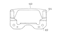
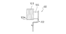
従来のダイナミックダンパには、そのゴム状弾性体の取付け方法により、接着式と非接着式とに分類される。例えば、図16及び図17に示す接着式ダイナミックダンパ100は、振動系である車両のボディフレームに取り付けられる取付け部材102と、振動系の振動を抑制するための質量体103と、前記取付け部材102と質量体103との間に介在されて加硫接着されるゴム状弾性体104とを備えている。質量体103は、複数枚の金属製板材103aを積層固着して、振動系の共振周波数にチューニング可能な質量に調整されている。
【0003】
【発明が解決しようとする課題】
しかしながら、この加硫接着方式のダイナミックダンパ100では、金型内で加硫接着を行うので、振動系に合わせて質量を調整する場合、金属製板材103aの積層体の幅に応じて金型のキャビティを変更しなければならず、金属製板材103aの積層幅が大きくなればなるほど金型が大型化せざるを得なかった。
【0004】
しかも、加硫接着方式の場合、質量体103と取付け部材102のそれぞれにゴム用接着剤を塗布する加硫前処理工程が必要となり、工程数の増大によりコスト高となる難点がある。
【0005】
一方、非接着式の場合、接着方式に比べて加硫前処理工程が不要の分、コストの低減が図れる可能性があるが、質量体あるいは取付け部材からのゴム状弾性体の抜け止め手段に創意工夫が必要であった。
【0006】
【課題を解決するための手段】
本発明は、ダイナミックダンパとして非接着方式を採用して加硫前処理工程を不要とするととともに、質量体及び取付け部材からのゴム状弾性体の抜け止めも図るために、ゴム状弾性体の本体の先端側に質量体を保持する保持部を、基端側に取付け部材を保持する保持部を一体的に形成し、これら保持部に質量体及び取付け部材を弾性的に保持させた構成を採用したものである。この質量体及び取付け部材の保持部は、ゴム状弾性体の組成と同じものとなり、保持部自体に弾性を有することになるので、その弾性を利用して質量体及び取付け部材を抜け出し不能に保持でき、ボルトやビスによる固定方式に比べて製造工程が簡略化できる点で有利である。
【0007】
ここで、質量体は、脚部とその上側に該脚部よりも幅広に一体形成された質量部とを有する構成であり、また、取付け部材は、振動系である車両ボディフレームに取付け固定される固定部と、その上側に一体的に形成された垂直状態の支持部とを備えたものである。これらの最適な態様の質量体として、一対の脚部間に本体を差し渡し形成したアーチ型のものを例示でき、また取付け部材として、固定部の左右両側に前記質量体の脚部に対向するように一対の支持部を立設させた構成を例示できる。
【0008】
ゴム状弾性体の質量体側保持部及び取付け部材側保持部の構成としては、種々の態様が採用でき、また、質量体と取付け部材の保持態様も同様な態様、あるいは異なる態様のいずれをも採用できる。その保持部の構成態様としては、2方向保持方式、3方向保持方式、あるいは差込み保持方式を例示することができる。
【0009】
2方向保持方式としては、保持部を環状に形成された保持環で構成して、この保持環をその弾性を利用して拡径することにより、質量体の脚部や取付け部材の支持部を差込み可能とし、かつ弾性的に保持する方式をいい、これにより、質量体の脚部及び取付け部材の水平方向の移動を拘束しつつ保持することが可能である。この2方向保持方式を質量体側保持部及び取付け部材側保持部の両方とも採用すれば、保持環の成形において、上型と下型の割り型構造の金型を採用して、簡単に保持部の形成が可能となり、脱型が極めて容易に行える点で有利である。
【0010】
3方向保持方式とは、上記保持環の他に、これらの上方に質量体の頭部や取付け部材の支持部上端に当接する規制片を付設する構成であり、この規制片を設けることにより、質量体は、ゴム状弾性体に対して上方向への移動が規制される。一方、質量体の質量部が脚部よりも幅広に形成されているので、質量部が保持環の上縁に当接して下方向への抜け止めが可能となり、結局、上下方向の移動が規制されることになり、さらに、保持環との相互作用により、全体として3方向の移動が規制されることになる。一方、取付け部材側においては、規制片が支持部の上端に当たり、ゴム状弾性体の下方向への移動が規制されることになる。
【0011】
このような3方向保持方式を質量体側及び取付け部材側の両方で採用したとしても、保持環の規制片が存在しない側は開放状態となっているため、割り型構造の金型を使用した場合、開放側からの脱型が容易に行える点で2方向保持方式と比べて遜色のない成形が可能となる。
【0012】
なお、質量体では、質量部が脚部よりも幅広に形成されているため、保持環への差し込みは、脚部から行われることになる。この際、規制片が脚部の差込みを阻害する可能性もあるが、保持環と規制片との間に脚部差し込み空間が形成されれば、脚部はスムーズに保持環に差し込むことが可能である。
【0013】
また、上記規制片の形成位置を質量体及び取付け部材の構成に合わせて保持環の上側に限定したが、質量体の質量部と脚部の位置関係、あるいは取付け部材の固定部と支持部の位置関係が上下逆転している場合、規制片の形成位置も保持環の下側となることは勿論である。
【0014】
次に、差込み保持方式について説明すると、これは、質量体や取付け部材に水平方向に係合孔を貫通形成し、この係合孔に挿通される貫通軸部と、その先端に係合孔よりも大径に形成され、係合孔に弾性変形を利用して貫通されると共に該係合孔から抜け出し不能とされた抜け止め頭部とを含む構成である。
【0015】
このような構成を採用すれば、貫通軸部を質量体や取付け部材の係合孔に貫通させるだけで、質量体、取付け部材、及びゴム状弾性体の組み付けが可能となり、その組み付けが容易に行えることになる。この場合、質量体構成は、脚部及び質量部から構成されるものに限らず、いかなる形状のものにも適用できる。同様に、取付け部材の構成も固定部と支持部とから構成されるものに限定されない。
【0016】
なお、ゴム状弾性体による質量体と取付け部材との保持方式は、上述の通り、2方向保持方式、3方向保持方式、及び差込保持方式のうちのいずれかを採用すればよく、例えば、質量体及び取付け部材ともに2方向保持方式を採用する構成や、質量体は2方向保持方式を、取付け部材は3方向保持方式を夫々採用する構成や、さらには、質量体に差込保持方式を、取付け部材に2方向保持方式を夫々採用する構成も採用可能である。
【0017】
【発明の実施の形態】
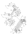
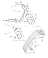
以下、本発明の実施の形態を図面に基づいて説明する。図1ないし図6は第1の実施の形態を示すもので、図1は、第1の実施の形態を示す非接着式ダイナミックダンパの取付け状態を示す断面図、図2はダイナミックダンパの分解斜視図、図3はダイナミックダンパの組み付け状態を示す正面図、図4は同じくその側面図、図5はゴム状弾性体の正面図、図6はその側面図である。
【0018】
図示のごとく、本実施の形態におけるダイナミックダンパ1は、3方向保持方式を採用したものであり、振動系2へ取り付けられる取付け部材3と、振動系2の振動を抑制するための質量体4と、前記取付け部材3と質量体4との間に介在されるゴム状弾性体5とを備えている。
【0019】
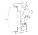
図1は振動系2としてステアリングハンドル部の構造を例示したもので、ハンドル軸の軸装部6に取付け部材3がボルト8により取付けられており、その前面にホーンカバー9が被装された状態を示すものである。
【0020】
図2のごとく、取付け部材3は、略馬蹄形の金属製板材の中間部を後方へ側面視L字形に折曲形成することにより、その下側に軸装部6の前面にボルト8により固定される垂直状態の固定部12が形成され、上側には側面視L字形の左右一対の支持部13が形成されている。
【0021】
質量体4は、複数枚の金属製板材4aを積層固着して、振動系の共振周波数にチューニング可能な質量に調整されるもので、全体として、一対の脚部15と、その上端間に差し渡された質量部16とからアーチ型に形成されなるものであり、従って、質量部16の幅は脚部15に比べて幅広に形成されている。この脚部15の左右両側面には、後述するゴム状弾性体5の保持環18の上下方向の抜け止めを図るために、保持環18の上下幅に対応した幅の凹部19が形成されている。また、脚部15の上側の質量部16の上面には、ゴム状弾性体5の規制片20に対応した左右幅の凹部21が形成されている。
【0022】
ゴム状弾性体5は、本体23と、その先端側で質量体4の脚部15を係合保持する先端側保持部24と、本体22の基端側で取付け部材3に係合保持される基端側保持部25とが一体的に形成されている。
【0023】
このゴム状弾性体5は、一般的に防振ゴムに使用される天然ゴム、あるいは合成ゴム、例えば、SBR(スチレンブタジエンゴム)、BR(ブタジエンゴム)、IR(イソプレンゴム)、NBR(アクリルニトリルブタジエンゴム)、CR(クロロプレンゴム)、IIR(ブチルゴム)、EPDM(エチレンプロピレンゴム)、あるいはウレタンエラストマーなどが使用される。これらの原料ゴムに加硫剤、加硫促進剤、老化防止剤、補強剤、充填剤、軟化剤等の配合剤を入れて、所定の弾性率、機械的強度、動的特性、疲労特性などが得られるようにする。
【0024】
本実施の形態におけるゴム状弾性体5の本体23は、図2のごとく、直方体状に形成されている。また、先端側保持部24は、質量体4の脚部15を上方から差込可能で、脚部15を弾性的に保持して質量体4の水平方向の移動を規制する保持環18と、質量体4の上面部に弾性的に当接して質量体4の上方への抜け出しを防止する規制片20とを備えている。
【0025】
保持環18は、本体23の前面に薄肉状のU字形帯片を一体成形することにより、本体23の前面を利用して環状に形成されており、その内径は、自由状態において、質量体4の脚部15の外径よりも僅かに小径とされている。なお、保持環18は、環状の帯片を本体23に一体成形することによっても構成することが可能である。
【0026】
規制片20は、保持環18の前端部から本体23の上端部に亘って差し渡し形成された帯片であって、この規制片20と保持環18との間には、質量体4の脚部15を差込み可能な差込空間27が形成されている。
【0027】
基端側保持部25は、取付け部材3の支持部13に上方から係合可能で、支持部13に弾性的に保持される保持環28と、取付け部材3の支持部13の上端に当接してゴム状弾性体5の下方への移動を規制する規制片29とを備えている。
【0028】
取付け部材側の保持環28は、本体23の後面に薄肉状のU字形帯片を一体成形することにより、本体23の後面を利用して環状に形成されており、その内径は、自由状態において、取付け部材3の支持部13の外径よりも僅かに小径とされている。なお、取付け部材側の保持環28は、環状の帯片を本体23に一体成形することによっても構成することが可能である。取付け部材3側の規制片29も、保持環28の後端部から本体23の上端部に亘って差し渡し形成された帯片によって構成されている。
【0029】
これら先端側保持部24と基端側保持部25は、上下の割り型構造の成形金型を用いて、ゴム本体23と一体的に加硫成形されるもので、この際、規制片20、29は、保持環18、28の上側のみに位置していることから、上下の金型の脱型も容易であり、成形が容易に行える利点がある。
【0030】
このゴム状弾性体5に質量体4及び取付け部材3を組み付けるには、まず、上記のように加硫成形されたゴム状弾性体5の先端側保持部24の保持環18と規制片20との間の差し込み空間27から、質量体4の脚部15を、保持環18の弾性力に抗して、その側面凹部19が保持環18に嵌合するまで挿入する。次に、規制片20を弾性変形させ、質量体4の上面部の凹部21に入り込むまで持ち上げて、質量体4の上面部に規制片20を当接させる。
【0031】
そうすると、質量体4は、保持環18によって弾性的に保持され、水平方向の移動及び抜け出しが拘束されることになる。また、規制片20によって、上方向の抜け出しも拘束されることになる。また、質量体4の質量部16は、脚部15に対して左右方向に突出しているから、質量部16と保持環18の上縁とが当接すれば、質量体4の下方向への移動・抜け出しが拘束される。
【0032】
次に、基端側保持部25の保持環28を、その弾性力に抗して拡径させながら、上方から取付け部材3の支持部13に挿入し、規制片29を支持部13の上端に当接する。これにより、保持環28が支持部13を弾性的に保持することになり、水平方向の抜け出しを拘束し、また、規制片29によりゴム状弾性体5の下方への移動が規制されることになる。
【0033】
このように、本実施の形態では、非接着方式を採用して、質量体及び取付け部材とゴム状弾性体との取付けは、ゴム状弾性体の弾性を利用した保持方式を採用しているので、従来の加硫接着型のダイナミックダンパに比べて、接着剤塗布工程が省略でき、また、金型構造もゴム状弾性体5のみの成形となるため小型なものとできるなどの利点がある。
【0034】
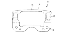
図7ないし図11は本発明の第2の実施の形態を示すもので、図7はダイナミックダンパの分解斜視図、図8はダイナミックダンパの組み付け状態を示す正面図、図9は同じくその側面図、図10はゴム状弾性体の正面図、図11はその側面図である。
【0035】
図示のごとく、本実施の形態におけるダイナミックダンパ31は、2方向保持方式を採用したものであり、第1の実施の形態におけるダイナミックダンパ1と異なる点は、先端側保持部24及び基端側保持部25における規制片20、29を廃止した点、及びこれに伴い、質量体4の上面部の凹部21を廃止した点であり、その他の構成は上記第1実施の形態と同様である。
【0036】
この第2の実施の形態では、規制片20,29を廃止しているが、その場合においても、保持環18、28の弾性力により質量体4の脚部15及び取付け部材3の支持部13を十分を拘束することができ、水平方向の移動を拘束することが可能となる。また、質量体4の脚部15には依然として凹部19が存在するため、この凹部19とこれに嵌合した保持環18とにより、質量体の上下方向の移動も規制されることになる。
【0037】
なお、取付け部材3側の支持部13では、質量体4に相当する凹部19が存在していないが、保持環28の保持能力を補うため、支持部13にも折曲凹部を形成することにより、ゴム状弾性体5の上方への抜け出しを確実に防止することも可能である。
【0038】
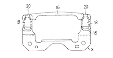
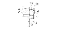
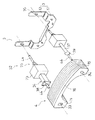
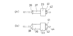
図12ないし図15は本発明の第3の実施の形態を示すもので、図12はダイナミックダンパの分解斜視図、図13はダイナミックダンパの組み付け状態を示す正面図、図14はその側面図、図15はゴム状弾性体の側面図で、(a)は右側ゴム状弾性体を、(b)は左側ゴム状弾性体を夫々示す。
【0039】
図示のごとく、第3の実施の形態のダイナミックダンパ32は、差し込み保持方式を採用したものであり、質量体4及び取付け部材3に夫々ゴム状弾性体5と係合する係合孔33,34,35が形成されたものである。
【0040】
すなわち、質量体4は、上記第1の実施の形態と同様に、一対の脚部15と質量部16とからアーチ型に形成された基本構成に変わりはないが、脚部15に水平方向に係合孔33,34が貫通形成されている。取付け部材3も固定部12と支持部13とからなる基本構成に変わりはないが、支持部13に水平方向に係合孔35が形成されている。
【0041】
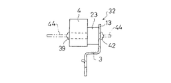
ゴム状弾性体5は、本体23、先端側保持部24及び基端側保持部25からなる基本構成は上記実施の形態と同様であるが、先端側保持部24及び基端側保持部25の形状が相違する。
【0042】
先端側保持部24は、質量体4の係合孔33,34に挿通される貫通軸部36,37と、その先端に質量体4の係合孔33,34よりも大径に形成され、係合孔33,34に弾性変形を利用して貫通されると共に該係合孔33,34から抜け出し不能とされた抜け止め頭部38、39とを備えたものである。
【0043】
本実施の形態では、図12において、左側の貫通軸部36が角柱形に形成されており、その抜け止め頭部38が角錐形に形成されている。右側の貫通軸部37は円柱状に形成され、その先端抜け止め頭部39は円錐形に形成されている。これに合わせて、質量体4の左脚部15の係合孔33は角孔とされ、右脚部15の係合孔34が円孔とされている。
【0044】
一方、基端側保持部25は、支持部13の係合孔35に挿通される断面円形の貫通軸部41と、その先端に係合孔35よりも大径に形成され、係合孔35に弾性変形を利用して貫通されると共に該係合孔35から抜け出し不能とされた円錐形の抜け止め頭部42とを備えている。本実施の形態では、左右の支持部13の係合孔35の形状は同じものとされている。
【0045】
これらの貫通軸部36、37、41の軸方向長さは、貫通する質量体4あるいは支持部13の軸方向幅に合わせて、それよりも僅かに短く形成することにより、貫通軸部36,37,41の弾性を利用して抜け止め頭部38、39、42と本体23との間に質量体4あるいは支持部13を挟圧し、軸方向の移動を拘束するとともに、これと直交する方向の移動も阻止する態様としている。特に、貫通軸部36が角柱形に形成されている場合には、質量体4に対する回り止め機能を発揮することになる。
【0046】
また、これらの抜け止め頭部38、39、42は、夫々の係合孔に弾性変形を利用して貫通させるものであるため、頭部38、39、42を係合孔33、34、35から引き出し易くする細径の引き出し軸部44が頭部に一体的に形成されており、この引き出し軸部44は、頭部38,39,42を係合孔33,34,35に貫通させた後、切断する形式を採用している。
【0047】
本実施の形態では、引き出し軸部44は、ゴム状弾性体5と同様なゴム組成であり、ゴム状弾性体の成形時に同時に成形される。なお、引き出し軸部44は、上記のように、ゴム素材で作成する以外に、剛性のある樹脂、あるいは鋼線などを使用してもよく、この場合も、ゴム状弾性体の加硫成形時に一体的に成形すればよい。
【0048】
また、質量体側の貫通軸部36、37の断面形状を左右の軸部で変更したが、両者が同じ断面形状であってもよいことは勿論であり、支持部13の貫通軸部41を左右で変更してもよいことは勿論である。
【0049】
このような差し込み方式は、貫通軸部と抜け止め頭部とからなる簡単な構成であるため、金型構造も簡単になり、また、質量体4及び取付け部材3との組み付け作業も、抜け止め頭部38、39、42を夫々係合孔33、34、35を貫通させるだけであるので、簡単に行えることになる。
【0050】
【発明の効果】
以上の説明から明らかな通り、本発明によると、非接着方式を採用して加硫前処理工程を不要とし、ゴム状弾性体の本体の先端側に質量体を保持する保持部を、基端側に取付け部材を保持する保持部を一体的に形成し、これら保持部に質量体及び取付け部材を弾性的に保持させることにより、これらの抜け止めを可能となるといった優れた効果がある。
【図面の簡単な説明】
【図1】本発明の第1の実施の形態を示す非接着式ダイナミックダンパの取付け状態を示す断面図
【図2】同じくダイナミックダンパの分解斜視図
【図3】同じくダイナミックダンパの組み付け状態を示す正面図
【図4】同じくその側面図
【図5】同じくゴム状弾性体の正面図
【図6】同じくその側面図
【図7】第2の実施の形態を示すダイナミックダンパの分解斜視図
【図8】同じくダイナミックダンパの組み付け状態を示す正面図
【図9】同じくその側面図
【図10】同じくゴム状弾性体の正面図
【図11】同じくその側面図
【図12】第3の実施の形態を示すダイナミックダンパの分解斜視図
【図13】同じくダイナミックダンパの組み付け状態を示す正面図
【図14】同じくその側面図
【図15】同じくゴム状弾性体の側面図で、(a)は右側ゴム状弾性体を、(b)は左側ゴム状弾性体を夫々示す。
【図16】従来の接着式ダイナミックダンパの正面図
【図17】同じくその側面図
【符号の説明】
1、31、32 ダイナミックダンパ
3 取付け部材
4 質量体
5 ゴム状弾性体
12 固定部
13 支持部
15 脚部
16 質量部
18、28 保持環
20、29 規制片
23 本体
24 先端側保持部
25 基端側保持部
33、34,35 係合孔
36、37,41 貫通軸部
38、39,42 抜け止め頭部
44 引き出し軸部[0001]
BACKGROUND OF THE INVENTION
The present invention relates to a non-adhesive dynamic damper that is tuned to a resonance frequency of a vibration system and suppresses vibration of the vibration system.
[0002]
[Prior art]
Conventional dynamic dampers are classified into an adhesive type and a non-adhesive type depending on the attachment method of the rubber-like elastic body. For example, an adhesive
[0003]
[Problems to be solved by the invention]
However, in this vulcanization adhesion type
[0004]
In addition, in the case of the vulcanization adhesion method, a vulcanization pretreatment process in which a rubber adhesive is applied to each of the
[0005]
On the other hand, in the case of the non-adhesive type, there is a possibility that the cost can be reduced because the vulcanization pretreatment step is unnecessary compared with the adhesive type, but it is a means for preventing the elastic elastic body from coming off from the mass body or the mounting member. Ingenuity was necessary.
[0006]
[Means for Solving the Problems]
The present invention adopts a non-adhesive method as a dynamic damper, eliminates the need for a pre-vulcanization treatment step, and prevents the elastic elastic body from coming off from the mass body and the mounting member. A configuration is adopted in which a holding part for holding the mass body is integrally formed on the distal end side, and a holding part for holding the attachment member is integrally formed on the base end side, and the mass body and the attachment member are elastically held by these holding parts. It is a thing. The holding part of the mass body and the attachment member has the same composition as that of the rubber-like elastic body, and the holding part itself has elasticity. This is advantageous in that the manufacturing process can be simplified compared to the fixing method using bolts or screws.
[0007]
Here, the mass body is configured to include a leg portion and a mass portion integrally formed on the upper side of the leg portion so as to be wider than the leg portion, and the attachment member is attached and fixed to a vehicle body frame that is a vibration system. And a vertical support portion formed integrally therewith. As the mass body of these optimum modes, an arch type body in which the main body is inserted and formed between a pair of leg portions can be exemplified, and the mounting member is opposed to the leg portions of the mass body on both the left and right sides of the fixing portion. A configuration in which a pair of support portions are erected can be exemplified.
[0008]
Various configurations can be adopted as the configuration of the mass body side holding portion and the mounting member side holding portion of the rubber-like elastic body, and the mass body and the mounting member are held in the same mode or in different modes. it can. Examples of the configuration of the holding unit include a two-way holding method, a three-way holding method, and an insertion holding method.
[0009]
As a two-way holding system, the holding part is configured by a holding ring formed in an annular shape, and the diameter of the holding ring is expanded by utilizing its elasticity, whereby the leg part of the mass body and the support part of the attachment member are provided. It refers to a system that can be inserted and elastically held, and can thereby hold the leg of the mass body and the mounting member while restraining the movement in the horizontal direction. If this two-way holding system is used for both the mass-side holding part and the attachment-member-side holding part, the holding ring can be easily formed by adopting a split mold structure of an upper mold and a lower mold. This is advantageous in that it can be formed and demolding can be performed very easily.
[0010]
In addition to the holding ring, the three-way holding method is a configuration in which a restriction piece that abuts on the head of the mass body and the upper end of the support portion of the mounting member is attached above these holding rings. By providing this restriction piece, The mass body is restricted from moving upward relative to the rubber-like elastic body. On the other hand, since the mass part of the mass body is formed wider than the leg part, the mass part comes into contact with the upper edge of the retaining ring and can be prevented from coming down downward. Furthermore, the movement in the three directions as a whole is restricted by the interaction with the retaining ring. On the other hand, on the attachment member side, the restriction piece hits the upper end of the support portion, and the downward movement of the rubber-like elastic body is restricted.
[0011]
Even when such a three-way holding method is adopted on both the mass body side and the mounting member side, the side where the retaining piece of the retaining ring does not exist is in an open state. Compared to the two-direction holding method, molding that is comparable to the two-way holding method is possible in that the mold can be easily removed from the open side.
[0012]
In the mass body, since the mass portion is formed wider than the leg portion, insertion into the holding ring is performed from the leg portion. At this time, there is a possibility that the restricting piece may prevent the leg from being inserted, but if the leg insertion space is formed between the retaining ring and the restricting piece, the leg can be smoothly inserted into the retaining ring. It is.
[0013]
In addition, the formation position of the restriction piece is limited to the upper side of the holding ring in accordance with the configuration of the mass body and the mounting member, but the positional relationship between the mass portion and the leg portion of the mass body, or between the fixing portion and the support portion of the mounting member. When the positional relationship is reversed up and down, of course, the formation position of the restricting piece is also below the holding ring.
[0014]
Next, the insertion holding system will be described. This is because the engaging hole is formed through the mass body and the mounting member in the horizontal direction, the through shaft portion inserted through the engaging hole, and the engaging hole at the tip thereof. Is also configured to include a retaining head that is formed in a large diameter, penetrates the engagement hole using elastic deformation, and cannot be removed from the engagement hole.
[0015]
By adopting such a configuration, it is possible to assemble the mass body, the mounting member, and the rubber-like elastic body simply by penetrating the through shaft portion through the engagement hole of the mass body or the mounting member. You can do it. In this case, the configuration of the mass body is not limited to the configuration including the leg portion and the mass portion, and can be applied to any shape. Similarly, the configuration of the attachment member is not limited to that constituted of a fixed portion and a support portion.
[0016]
In addition, the holding method of the mass body and the mounting member by the rubber-like elastic body may adopt any one of the two-way holding method, the three-way holding method, and the insertion holding method as described above. Both the mass body and the mounting member adopt a two-way holding method, the mass body adopts a two-way holding method, the mounting member adopts a three-way holding method, and further, the mass member has an insertion holding method. In addition, it is possible to adopt a configuration in which a two-way holding method is employed for each attachment member.
[0017]
DETAILED DESCRIPTION OF THE INVENTION
Hereinafter, embodiments of the present invention will be described with reference to the drawings. 1 to 6 show a first embodiment. FIG. 1 is a cross-sectional view showing a mounting state of a non-adhesive dynamic damper showing the first embodiment. FIG. 2 is an exploded perspective view of the dynamic damper. 3 is a front view showing the assembled state of the dynamic damper, FIG. 4 is a side view thereof, FIG. 5 is a front view of a rubber-like elastic body, and FIG. 6 is a side view thereof.
[0018]
As shown in the figure, the
[0019]
FIG. 1 shows an example of the structure of a steering handle portion as a
[0020]
As shown in FIG. 2, the
[0021]
The
[0022]
The rubber-like
[0023]
This rubber-like
[0024]
The
[0025]
The retaining
[0026]
The restricting
[0027]
The proximal-
[0028]
The retaining
[0029]
The distal end
[0030]
In order to assemble the
[0031]
Then, the
[0032]
Next, the diameter of the holding
[0033]
As described above, in the present embodiment, the non-adhesive method is adopted, and the mass body, the attachment member, and the rubber-like elastic body are attached using the holding method utilizing the elasticity of the rubber-like elastic body. Compared to a conventional vulcanization-adhesive dynamic damper, the adhesive application step can be omitted, and the mold structure can be made compact because only the rubber-like
[0034]
FIGS. 7 to 11 show a second embodiment of the present invention. FIG. 7 is an exploded perspective view of the dynamic damper, FIG. 8 is a front view showing the assembled state of the dynamic damper, and FIG. 9 is a side view of the same. 10 is a front view of the rubber-like elastic body, and FIG. 11 is a side view thereof.
[0035]
As shown in the figure, the
[0036]
In the second embodiment, the
[0037]
In addition, in the
[0038]
12 to 15 show a third embodiment of the present invention. FIG. 12 is an exploded perspective view of the dynamic damper, FIG. 13 is a front view showing an assembled state of the dynamic damper, and FIG. 14 is a side view thereof. 15A and 15B are side views of the rubber-like elastic body. FIG. 15A shows the right-side rubber-like elastic body, and FIG. 15B shows the left-side rubber-like elastic body.
[0039]
As shown in the figure, the
[0040]
That is, the
[0041]
The rubber-like
[0042]
The distal end
[0043]
In the present embodiment, in FIG. 12, the left penetrating
[0044]
On the other hand, the proximal-
[0045]
The axial lengths of these through-
[0046]
Further, since these retaining
[0047]
In the present embodiment, the
[0048]
Moreover, although the cross-sectional shape of the through-
[0049]
Such an insertion method has a simple configuration including a through shaft portion and a retaining head portion, so that the mold structure is simplified, and the assembly work of the
[0050]
【The invention's effect】
As is clear from the above description, according to the present invention, the non-adhesive method is adopted, the vulcanization pretreatment step is not required, and the holding portion that holds the mass body on the distal end side of the main body of the rubber-like elastic body is A holding portion for holding the attachment member is integrally formed on the side, and the holding member is elastically held by the mass body and the attachment member, so that it is possible to prevent them from coming off.
[Brief description of the drawings]
FIG. 1 is a cross-sectional view showing an attachment state of a non-adhesive dynamic damper according to a first embodiment of the present invention. FIG. 2 is an exploded perspective view of the dynamic damper. FIG. 3 is an assembly state of the dynamic damper. Front view [FIG. 4] Same side view [FIG. 5] Same front view of rubber-like elastic body [FIG. 6] Same side view [FIG. 7] Disassembled perspective view of dynamic damper showing second embodiment [FIG. 8 is a front view showing the assembled state of the dynamic damper. FIG. 9 is a side view thereof. FIG. 10 is a front view of the rubbery elastic body. FIG. 11 is a side view of the rubber elastic body. FIG. 13 is a front view showing the assembled state of the dynamic damper. FIG. 14 is a side view of the dynamic damper. FIG. 15 is a side view of the rubber-like elastic body. ) Is a right rubber-like elastic body, (b) shows respectively a left rubber-like elastic material.
FIG. 16 is a front view of a conventional adhesive dynamic damper. FIG. 17 is a side view of the same.
1, 31, 32
Claims (5)
前記質量体が、脚部と、その上側に該脚部よりも幅広に一体形成された質量部とを有し、
前記ゴム状弾性体が、本体と、その先端側で前記質量体を弾性的に係合保持する先端側保持部と、前記本体の基端側で前記取付け部材を弾性的に係合保持する基端側保持部とが一体的に形成され、
前記先端側保持部が、前記質量体の脚部を上方から差込可能で、前記脚部を弾性的に保持して質量体の水平方向の移動を規制する保持環を含むことを特徴とする非接着式ダイナミックダンパ。A non-adhesive dynamic damper comprising an attachment member attached to a vibration system, a mass body that suppresses vibrations of the vibration system, and a rubber-like elastic body interposed between the attachment member and the mass body. ,
The mass body has a leg part and a mass part integrally formed wider on the upper side than the leg part,
The rubber-like elastic body includes a main body, a distal end side holding portion that elastically engages and holds the mass body on a distal end side thereof, and a base that elastically engages and holds the attachment member on a proximal end side of the main body. The end holding part is integrally formed ,
The tip side holding portion includes a holding ring that can insert the leg portion of the mass body from above and elastically holds the leg portion and restricts the movement of the mass body in the horizontal direction. Non-adhesive dynamic damper.
Priority Applications (1)
| Application Number | Priority Date | Filing Date | Title |
|---|---|---|---|
| JP23001897A JP4040724B2 (en) | 1997-08-26 | 1997-08-26 | Non-adhesive dynamic damper |
Applications Claiming Priority (1)
| Application Number | Priority Date | Filing Date | Title |
|---|---|---|---|
| JP23001897A JP4040724B2 (en) | 1997-08-26 | 1997-08-26 | Non-adhesive dynamic damper |
Publications (2)
| Publication Number | Publication Date |
|---|---|
| JPH1163093A JPH1163093A (en) | 1999-03-05 |
| JP4040724B2 true JP4040724B2 (en) | 2008-01-30 |
Family
ID=16901291
Family Applications (1)
| Application Number | Title | Priority Date | Filing Date |
|---|---|---|---|
| JP23001897A Expired - Fee Related JP4040724B2 (en) | 1997-08-26 | 1997-08-26 | Non-adhesive dynamic damper |
Country Status (1)
| Country | Link |
|---|---|
| JP (1) | JP4040724B2 (en) |
Families Citing this family (2)
| Publication number | Priority date | Publication date | Assignee | Title |
|---|---|---|---|---|
| US6782981B2 (en) * | 2002-12-30 | 2004-08-31 | Paulstra Crc | Antivibration apparatus including a mass damper |
| JP5027326B1 (en) * | 2011-07-26 | 2012-09-19 | 備前発条株式会社 | Dynamic damper |
-
1997
- 1997-08-26 JP JP23001897A patent/JP4040724B2/en not_active Expired - Fee Related
Also Published As
| Publication number | Publication date |
|---|---|
| JPH1163093A (en) | 1999-03-05 |
Similar Documents
| Publication | Publication Date | Title |
|---|---|---|
| EP2371600B1 (en) | Stopper structure of torque rod | |
| EP3018381B1 (en) | Vibration-damping structure | |
| CN109070830A (en) | Coupling arrangement for can quiveringly be fixed on air bag module on steering wheel for vehicle | |
| JP2004003597A (en) | Anti-vibration support device | |
| EP1432598A1 (en) | Mounting structure of a vehicle interior part | |
| EP2505890B1 (en) | Clamp | |
| JP5758136B2 (en) | handle | |
| KR100811693B1 (en) | Pedal switch fixing device of car | |
| US8118515B2 (en) | Coupling rod for vehicle suspension system | |
| JP4040724B2 (en) | Non-adhesive dynamic damper | |
| KR20180114572A (en) | Steering wheel damper | |
| US9994166B2 (en) | Dual molded grab handle spacer for a motor vehicle | |
| KR101823968B1 (en) | Roll-rod for vehicle | |
| JP2006052806A (en) | Cushion clip | |
| KR101816750B1 (en) | Active roll-rod for vehicle | |
| JP3700580B2 (en) | Piping clamp | |
| JP3486818B2 (en) | Bush type anti-vibration rubber | |
| KR200486026Y1 (en) | Auxiliary handle for vehicles | |
| JP3521554B2 (en) | Dynamic damper | |
| JP2007292150A (en) | Rubber mount | |
| CN111663875A (en) | Vehicle front cover assembly and vehicle | |
| KR101754642B1 (en) | Roll-rod for vehicle | |
| JP7280813B2 (en) | Fastener | |
| JP2005308054A (en) | Clamp | |
| JP2020060222A (en) | Cylindrical vibration controller |
Legal Events
| Date | Code | Title | Description |
|---|---|---|---|
| A621 | Written request for application examination |
Free format text: JAPANESE INTERMEDIATE CODE: A621 Effective date: 20040709 |
|
| A977 | Report on retrieval |
Free format text: JAPANESE INTERMEDIATE CODE: A971007 Effective date: 20061222 |
|
| A131 | Notification of reasons for refusal |
Free format text: JAPANESE INTERMEDIATE CODE: A131 Effective date: 20070410 |
|
| A521 | Written amendment |
Free format text: JAPANESE INTERMEDIATE CODE: A523 Effective date: 20070507 |
|
| TRDD | Decision of grant or rejection written | ||
| A01 | Written decision to grant a patent or to grant a registration (utility model) |
Free format text: JAPANESE INTERMEDIATE CODE: A01 Effective date: 20071106 |
|
| A61 | First payment of annual fees (during grant procedure) |
Free format text: JAPANESE INTERMEDIATE CODE: A61 Effective date: 20071108 |
|
| FPAY | Renewal fee payment (event date is renewal date of database) |
Free format text: PAYMENT UNTIL: 20101116 Year of fee payment: 3 |
|
| R150 | Certificate of patent or registration of utility model |
Free format text: JAPANESE INTERMEDIATE CODE: R150 |
|
| FPAY | Renewal fee payment (event date is renewal date of database) |
Free format text: PAYMENT UNTIL: 20131116 Year of fee payment: 6 |
|
| LAPS | Cancellation because of no payment of annual fees |