JP4040682B2 - Desktop bookbinding apparatus and tape having alignment means - Google Patents
Desktop bookbinding apparatus and tape having alignment means Download PDFInfo
- Publication number
- JP4040682B2 JP4040682B2 JP53284297A JP53284297A JP4040682B2 JP 4040682 B2 JP4040682 B2 JP 4040682B2 JP 53284297 A JP53284297 A JP 53284297A JP 53284297 A JP53284297 A JP 53284297A JP 4040682 B2 JP4040682 B2 JP 4040682B2
- Authority
- JP
- Japan
- Prior art keywords
- tape
- bookbinding
- binding
- bundle
- adhesive
- Prior art date
- Legal status (The legal status is an assumption and is not a legal conclusion. Google has not performed a legal analysis and makes no representation as to the accuracy of the status listed.)
- Expired - Lifetime
Links
Images


Classifications
-
- B—PERFORMING OPERATIONS; TRANSPORTING
- B42—BOOKBINDING; ALBUMS; FILES; SPECIAL PRINTED MATTER
- B42C—BOOKBINDING
- B42C9/00—Applying glue or adhesive peculiar to bookbinding
- B42C9/0056—Applying glue or adhesive peculiar to bookbinding applying tape or covers precoated with adhesive to a stack of sheets
-
- B—PERFORMING OPERATIONS; TRANSPORTING
- B42—BOOKBINDING; ALBUMS; FILES; SPECIAL PRINTED MATTER
- B42D—BOOKS; BOOK COVERS; LOOSE LEAVES; PRINTED MATTER CHARACTERISED BY IDENTIFICATION OR SECURITY FEATURES; PRINTED MATTER OF SPECIAL FORMAT OR STYLE NOT OTHERWISE PROVIDED FOR; DEVICES FOR USE THEREWITH AND NOT OTHERWISE PROVIDED FOR; MOVABLE-STRIP WRITING OR READING APPARATUS
- B42D3/00—Book covers
- B42D3/002—Covers or strips provided with adhesive for binding
Abstract
Description
発明の背景
1.発明の分野
本発明は、ばらの用紙を本に製本するデスクトップ型の製本装置であって、用紙をL形に成形された製本材料と整合させる装置が設けられた製本装置に係る。
2.従来技術の説明
ばらの用紙を本に製本するための多数の技法が過去数世紀に亘り開発されている。かかる方法の一つに於いては、ホットメルト接着剤にて被覆されたテープが使用され、また背部の内面にホットメルト接着剤を有する巻き付け型のフォルダが使用される。この方法に於いては、テープやフォルダは製本されるべき用紙の束のエッジの周りに巻き付けられ、しかる後接着剤が加熱される。接着剤は用紙に接着し、接着剤が冷却すると製本工程が完了する。
この方法に於ける一つの主要な問題はテープを用紙のエッジと正確に整合させることである。高度の解決策に於いては、センサや自動化された正確な機構を使用して整合状態にもたらされた用紙及テープが捕捉される。整合を達成する他の一つの方法はテープの断面をU形に成形することである。用紙はU形内に配置され、それらの組合せが加熱されることによって製本される。U形の幅は一定であるので、種々の大きさの多数のテープがストックされなければならない。
フォルダによる製本に於いては、用紙がフォルダ内に配置され、それらの組合せが加熱されることによって接着剤が溶融され、これにより製本が行われる。予めU形に成形されたテープの場合と同様、フォルダの幅は一定であるので、使用者は多数の大きさのテープをストックしなければならず、フォルダは高価であるのでコストが増大する。
種々の製本技法の例が下記の米国特許公報に開示されている。例えば米国特許第4,129,471号公報には、カバーフォルダがその背部領域に接着剤を有するシステムが開示されており、同第3,717,366号公報には、接着剤が折り曲げられたブックカバーの内側に適用されるシステム及びブックカバーを折り曲げる装置が開示されており、同第3,321,786号公報には、製本されるべき用紙を積層するプラットフォームと、積層された用紙のエッジを互いにクランプする持ち上げ要素と、積層された用紙のエッジに対し接着剤を適用する装置と、接着剤を所定の時間加熱する装置とを含む製本装置が開示されており、同第4,496,617号公報には、用紙の積層体を互いに結合する改良された製本ストリップが開示されており、同第3,757,736号公報には、用紙がカートリッジにクランプされ、用紙のエッジが第一の傾斜状態に於いて加振装置により整合され、予熱工程に備えてカートリッジが回転され、エッジにホットメルト接着剤が適用され、製本された用紙が冷却位置へ移動されるよう構成された製本装置が開示されている。
製本テープをプリンタに整合させることが困難であり、また製本テープはプリンタの用紙送給機構と両立しないので、加熱型の製本テープを印刷することも困難である。製本後に特殊なプリンタを使用することも可能であるが、かかる特殊なプリンタは本の背部しか印刷することができず、また白黒の印刷しかできず、更にはそれらが印刷し得る領域の大きさが制限される。更に一度に数冊の本しか製本されない場合には、特殊なプリンタにて背部を印刷することは非常に高価になる。必要に応じて本を印刷したりオフィス環境に於いて本を印刷する場合には、一般に本の数は少ない。かかる場合には、加熱により製本が行われた後に於ける本の背部は白紙の状態である。このことは面倒であると共に不便である。従って必要とされているものは、単純にして低廉な製本装置であって、用紙及びフォルダを製本装置により容易に製本することができ、一度に少数の本しか製本されない場合にも製本テープが製本装置内へ挿入される前に製本テープを単純に且つ経済的に容易に印刷することができる製本装置である。
本発明の概要
本発明は、製本されるべき用紙が製本テープそれ自身によって正確に整合され、また予め成形された製本テープによって種々の厚さの本を製本することができる単純な構成のデスクトップ型の製本方法及び製本装置を提供するものである。特に従来の製本テープがL形に成形される。L形の内側の角部及び用紙の束のエッジが互いに正確に係合することにより整合が達成される。L形の長い方の脚部は水平に配向される。
製本テープは製本装置に設けられた対応する形状の溝内に挿入され、用紙の束が製本テープ上に配置され、用紙の束のエッジが製本テープの角部に対し自動的に整合される。L形の製本テープの長い方の脚部の自由端が用紙の束の周りにきつく巻き付けられ、これにより種々の厚さの用紙の束を処理することができる。
他の一つの構成に於いては、カバーの間に用紙の束を製本するのではなく用紙の束がスレートに似た形状を有する型に置き換えられる。型はテフロンテープにて覆われている。接着剤はテフロンに接着しないので、製本後に型を取り出すことができる。これによりカバー及び背部の内面に接着剤が塗布された製本テープが残される。従って使用者は自分自身のフォルダを形成することができ、必要なときに必要な数及び幅のフォルダを形成することができる。製本工程が開始される前にフォルダを形成するために使用されるカバーを従来のプリンタを使用して印刷することができる。従って融通性が向上し、またコストが大きく低減される。
製本テープはそれが所望のL形に折り曲げられる前の状態に於いては平坦である。他の一つの構成に於いては、製本テープはシートを形成するよう互いに横に並べられ、シートはリリースペーパの裏当てによって互いに保持される。通常のデスクトッププリンタにシートを通すことができ、テープのシートにテキスト、ラベル、タイトル、ロゴ、画像、バーコード等をカラーや白黒にて印刷することができる。製本テープは印刷されるとシートより剥し取られる。テープに予め形成された切り目線に沿ってL形の折り曲げ部が手動的に形成され、これにより予め印刷されたテープは製本に使用され得る状態になる。更に他の一つの構成に於いては、リリース接着剤の幅の狭いストリップのみを有するリリースペーパのシートが形成される。一つのテープが手動的に平坦にされ、接着剤の層が下側の状態でリリース接着剤のストリップに貼り付けられる。かくしてテープが貼り付けられたシートはプリンタに通すことが可能である。この方法によれば、一つのテープを通常のデスクトッププリンタにより印刷することができる。テープは印刷後にリリースペーパのシートより剥し取られる。テープは再度L形に手動的に折り曲げられ、製本に使用される。リリース接着剤のストリップが塗布された用紙は、リリース接着剤のストリップがテープに接着しなくなるまで数回再使用される。一つ又は複数のテープをシート状に組立てることにより、使用者自身のプリンタを使用してテープを予め印刷することができる。
L形の折り曲げ部を有するテープは製本装置の上端に設けられた溝内へ挿入される。テープの折り曲げ部の角部が溝の底面の角部と整合される。次いで用紙の束がテープ上に挿入される。次いで使用者は製本装置の一端に設けられたレバーを押し下げ、これにより製本工程を開始する。製本工程は用紙の束及び製本テープを互いに適正に整合された状態にてクランプする工程と、製本テープを用紙の束の周りに巻き付ける工程と、接着剤が用紙の束のエッジに接着するよう接着剤を溶融させる工程と、かくして組立てられた書類を冷却させる工程とを含んでいる。冷却時間の経過後にオペレータは製本装置の他方の端部に設けられたレバーを押し下げ、これにより製本された書類を解放し、製本装置を次の製本工程に備えてリセットする。
このユニークなL形のテープによれば、テープを用紙の束と容易に且つ正確に整合させることが可能であり、これにより製本装置の構造を単純化することができる。製本装置は後に詳細に説明する如く、可動のプラテンと、クランプストッパと、折り曲げ装置とを含み、折り曲げ装置の構造によりテープを用紙の束の周りにきつく正確に折り曲げることが確保される。
テープの接着剤を溶融させるために使用されるヒータはテープやフォルダを直接加熱する非常に小さいサーマルマスを有し、そのためウォームアップの必要がない。ヒータは迅速な冷却要件と両立する迅速な接着剤加熱サイクルを可能にする断熱材を含んでいる。製本テープの予熱によりテープを折り曲げる際に脆弱な書類を穏かに取り扱うことが可能になる。製本テープを制御された態様にて加熱することにより、従来の多くの製本テープの接着剤の厚さが不均一であることとは対照的に、実質的に均一な厚さの接着剤をテープに適用することができ、これにより製本テープのコストを低減し製本工程のコストを低減することができる。
本発明に於いて使用されるテープは使用者自身のプリンタによってテープを予め印刷することを可能にするシートに組み立て可能であり、シート状に組み立てられる際のテープの幅を適宜に選定することにより、オペレータは標準的なラベル形成ソフトウエアを使用することができ、また大抵のプリンタのエッジに沿って生じる印刷不可能な領域を回避することができる。
また製本に際し用紙に代えてテフロンにて被覆された除去可能な型が使用され、これにより使用者は後に使用される製本用フォルダを形成しカスタマイズすることができる。
かくして本発明によれば、使用者が必要とする多数の特徴を有する単純な構造の製本装置を比較的低廉に得ることができる。
【図面の簡単な説明】
図1は本発明による製本装置の斜視図である。
図2はL形の折り曲げ部を有する本発明による製本テープの斜視図である。
図3は図2の線3−3に沿う断面図である。
図3Aは図3の詳細図である。
図4はL形の製本テープに対し位置決めされた用紙の束の単純化された斜視図である。
図5はL形の製本テープ上に適正に配置された用紙の束の斜視図である。
図6はテープの折り曲げ変形が部分的に完了した状態を示す図5と同様の斜視図である。
図7はテープの折り曲げ変形が完了した状態を示す図6と同様の斜視図である。
図8はテープ及び用紙の束が挿入され整合される本発明による製本装置のキャビティの単純化された断面図である。
図9はテープ及び用紙の束が適正に挿入された状態を示す図8と同様の斜視図である。
図10は製本の開始時にプラテンが適正な位置にてテープ及び用紙の束をクランプストッパに対しクランプするよう移動された後の製本装置の溝を示している。
図11は製本中に於ける本発明による製本装置の構造、テープ、用紙を示す製本装置の単純化された斜視図である。
図12は製本工程完了後に於ける本発明による製本装置の構造、テープ、用紙を示す製本装置の単純化された斜視図である。
図13は本発明に於いて使用されるヒータ組立体の断面図である。
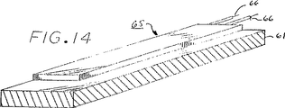
図14は本発明に於いて使用されるヒータ組立体の斜視図である。
図15は図12と同様製本工程が完了した状態を示す単純化された断面図であり、後に製本に使用されるフォルダを形成すべく用紙の束がテフロンにて被覆された除去可能な型に置き換えられた状態を示している。
図16は折り曲げ及び製本を行う前に使用者が予め印刷し得るようデスクトップ型のプリンタに挿入可能なシートを形成すべくリリースペーパに製本テープが配列された状態を示している。
図17は図16に示されたテープシートの断面図である。
図18は一つの製本テープのみが取り付けられたシートの斜視図である。
図19は図18に示されたシートの断面図であり、リリース接着剤が製本テープの下方の領域にのみ適用された状態を示している。
図20は始動位置又は完了位置について製本装置の右側の部分を示している。
図21は始動位置又は完了位置について製本装置の左側の部分を示している。
図22は用紙をクランプすべく下方へ移動された右側のハンドルを示している。
図23は用紙クランプ位置にて左側の部分を示している。
図24はリセットし歯車を解放すべくホイールが回転によって戻された状態にて右側の部分を示している。
図25はシステムがその始動位置に戻された状態にて解放された歯車を示している。
図26は製本装置の両側の部分が如何に互いに一緒に移動するかを示す断面図である。
図27は製本装置内に配置された用紙を示している。
図28はクランプされた用紙を示している。
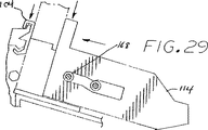
図29はクランプされ下方へ押庄された用紙を示している。
図30はヒータを冷却するファンを示している。
図31は図30の線31−31に沿う断面図である。
図32は本発明による製本装置の保管トレー部を示している。
図33は図32の線33−33に沿う断面図である。
図34は本発明による製本装置の幾つかの部品を示す単純化された断面図である。
図35は本発明の製本装置に使用される制御装置のブロック図である。
発明の説明
図1に本発明による製本装置10の斜視図が図示されている。製本されるべき材料は溝12に挿入され、材料はブックレスト14により垂直の状態に保持される。
後に詳細に説明する如く、右側のハンドル、即ちレバー16が押し下げられると、プラテン18が製本されるべき材料と共に前方へ移動される。製本されるべき材料がクランプストッパ20に到達すると、プラテンの移動が停止する。レバー16が更に押圧されるとスイッチが閉じられ、これにより製本工程が開始される。製本動作は発光ダイオードランプ22の点灯により示され、製本動作の完了はランプ22の消灯により示される。次いで左側のハンドル24が押し下げられ、これにより製本された本が解放され、製本機構が次の製本工程に備えてリセットされる。
製本されるべきに材料は用紙の束34(図4参照)と、随意のフロントカバー及びバックカバーと、製本テープ26とよりなっている。或いは背部に接着剤が塗布されたフォルダが製本に使用されてもよい。本発明によれば、製本テープ26がL形に折り曲げられ、テープ26の脚部27は用紙34に対する整合基準を与える。
製本テープは一方の側面にホットメルト接着剤の実質的に均一な厚さの層が被覆された紙又は布にて形成されることが好ましい。テープは幾つかの幅及び長さのストリップに切断される。かくして製本装置の使用者は製本されるべき書類に最も適したテープを選択することができる。
テープの詳細な断面図が図3に図示されており、図3はホットメルト接着剤の層28を示している。接着剤は溶融されると束状の用紙のエッジへ流動する。接着剤は冷却されると用紙、テープ及びカバーを互いに結合する。製本テープ26には紙又は布30が使用され、紙又は布30は製本後の背部に強度を付与する。図4に示されている如く予め折り曲げられた整合角部36を形成すべく、テープ26にはその製造中に切り目線32が形成される。切り目線32は折り曲げを容易にし、折り曲げ線が直線的であり、テープのエッジに平行であり、テープのエッジより適正に一様な距離の位置に位置することを確保する。用紙の束34及び製本テープ26は製本に先立って適正な方向に設定され、製本装置10の溝12に挿入される際に用紙の束34の整合されるエッジ38が予め折り曲げられた整合角部36に挿入される。
一般に製本テープ26の特徴は以下の通りである。

図5は製本テープ26に適正に挿入された用紙の束34を示しており、図6は用紙の束34の周りに製本テープ26が部分的に折り曲げられた状態を示しており、図7は用紙の束34の周りに対する製本テープ26の巻き付けが完了した状態を示しており、符号44は最後に折り曲げられた部分を示している。
図8は製本装置10の単純化された断面図であり、クランプストッパ20、可動プラテン18、背部フォイルヒータ46、折り曲げ装置用ヒータ48、プラテン用ヒータ50、ベース構造体51、枢動式折り曲げ装置52、折り曲げ装置用枢動ばね53、折り曲げ装置52を拘束した後解放するソレノイド54、圧縮バー57を示している。製本テープ26の整合角部36は底面整合角部55に挿入され、これに対し整合される。
図9は製本テープ26及び用紙の束34が適正に整合され配置された状態にて図8に示された部材と同一の部材を示している。
製本テープ26及び製本されるべき用紙の束34のエッジを正確に整合させることが重要である。従って製本テープ及び用紙が挿入される製本装置のキャビティ12は底面とプラテン18との間に底面の一方のエッジに沿って延在する鋭敏な直角の角部(底面整合角部55と呼ばれる)を有している。
製本テープ26は図示の如く底面整合角部55に対し手動的に整合される。製本されるべき用紙34は製本テープ26のL形の角部にてテープ上に配置される。次いで製本装置10が閉じられ、これにより製本テープはクランプされ加熱され用紙の束の反対側のエッジの周りに巻き付けられる状態になる。
製本されるべき本の厚さは数ページ乃至数inch(1inch=25.4mm)の範囲に於いて変動するので、用紙の束34の反対側のエッジの位置は一定ではない。
従って図10に示されている如く、用紙の束34及び製本テープ26はそれらが製本装置10内に於いてクランプストッパ20に対し押し付けられることによって互いに他に対しクランプされ、互いに他に対し所定の位置に固定される。クランプストッパ20は製本テープの二回目の折り曲げが正確に用紙の束34の反対側のエッジ58の位置に於いて行われるよう正確に位置決めされる。このことにより製本テープが用紙の束34の周りに非常にきつく巻き付けられる。
製本装置10の右側のハンドル16が押し下げられると、プラテン18が製本テープ26及び用紙の束34と共に移動する。従って用紙の束はクランプストッパ20に対しクランプされる。この段階に於いては、製本装置10は製本テープ26を加熱しそれを用紙の束34の周りに巻き付け得る状態にある。
図11は所定の加熱時間が経過した後に後退せしめられたソレノイド54のプランジャ59を示しており、この段階に於いては枢動式折り曲げ装置52の折り曲げ運動が開始されている。製本テープ26が室温の状態にある場合には、接着剤の層28により製本テープ26の剛性は幾分か高い状態にある。折り曲げの正確な位置を予測することができないので、製本テープ26の自由端には製本テープを弱くして折り曲げを容易にする切り目線は設けられていない。製本テープ26に圧力が与えられることによって折り曲げが行われる場合には、その圧力は用紙の束34へ伝達される。用紙の束34が薄く剛性が低い場合には、用紙の束34に与えられる圧力によって束が湾曲し変形することがある。
製本テープ26がその折り曲げ前に過剰に加熱されてしまうと、層28の接着剤が保持されず、流出して製本装置10の内部を汚してしまう。
従って製本テープ26の加熱は折り曲げが開始される前に開始される。用紙の束がクランプストッパ20に対しクランプされた後の約15秒が経過した時点に於いて接着剤の層28が柔軟ではあるが流出するほどではない状態になると、製本テープ26に対し圧力が与えられ、これにより製本テープの巻き付けが開始される。
従ってソレノイド54の解放には時間的遅延が存在する。この遅延時間中にヒータが製本テープ26を予熱する。この予熱により接着剤の層28が軟化され製本テープ26が非常に柔軟な状態にされる。
フォイルヒータ57に対し一定の電圧が印加される場合には、単位時間当りの温度上昇量をかなり正確に予測可能である。接着剤の層28が柔軟になる時点を推定することができ、単純なタイマを使用してその推定される時点に於いて製本テープの巻き付けを開始させることができる。或いは温度が測定されてもよい。
製本装置10は使用者の操作を要することなく110ボルト又は210ボルトにて動作するよう設計されている。220ボルトに於いては、温度の上昇速度は非常に高く、単純なタイマによっては接着剤の層の軟化が生じる時点を正確に予測することができない。
従って時間ではなく電流が計測され、電流は温度と共に線形的に変化するフォイルヒータの抵抗値に比例する。ヒータを或る温度まで上昇させるために使用される電圧の大きさに拘らずヒータがその或る温度に到達すると、接着剤の層28が軟化していると推定することができ、これにより製本テープの巻き付け工程を開始させることができる。折り曲げ工程の開始は、折り曲げ工程が開始される時点まで接着剤の層を加熱するに要する時間と呼ばれる所定の時間(前述の如く約15秒である)が経過した後にソレノイド54を解放することによって達成される。ヒータの時間に関するパラメータは接着剤の層28の溶融特性に依存する。製本テープは折り曲げ装置によって折り曲げられ、用紙の束34の用紙の周りに巻き付けられ、これにより製本された本が形成される。製本テープ26の断面形状はこの段階に於いてはU形である。接着剤の層28が製本された本の除去が可能であるほどに硬化するまでタイマによって製本された本が冷却される。
図12は製本工程の最終の位置にて製本装置の部材を示している。発光ダイオードランプ22が消灯した後、左側のハンドル24が押し下げられ、これにより製本された書類が解放されると共に、製本装置10が次の製本工程に備えてリセットされる。
図13は典型的なヒータ組立体(46〜50)の断面を示している。第一の層、即ち上層60はインクが予め印刷された製本テープよりヒータへ製本中に転移することを防止するテフロンを含んでいる。レーザプリンタにて予め印刷されたテープは熱溶融により固定されたトナーインクを有している。これらのテープが製本装置の高温の環境に於いて使用されると、トナーインクは軟化してヒータの表面へ部分的に転移する。従って時間の経過と共にインクによる汚れが許容し難いものになる。
従って各ヒータの外面はトナーインクが付着しないテフロン型の非常に薄い層にて被覆されている。テフロンの代わりに、これと同一の機能を果す特殊なシリコーンの如き他の材料が使用されてもよい。しかしかかる問題を解消すためには、インクジェットプリンタが使用されることが好ましい。
層64は物理的損傷を防止すると共に熱が一層均一に分散されるようアルミニウムを含んでいる。フォイルヒータ62はプリント回路板又は二つの絶縁層とそれらの間に互いに近接して隔置された抵抗導電体又はワイヤにて構成されていることが好ましい。
ヒータはそれらの上面及び下面の両方より熱を放射する。金属製の支持構造体は熱的アクセスが許容される場合には放射される熱のかなりの部分を吸収するが、製本後の冷却期間中には熱的アクセスが行われることが好ましい。従って断熱層63が設けられている。この断熱層の伝熱性は製本中に支持構造体へ熱が奪われることを防止し、しかも製本が完了した後に於ける冷却が可能であるよう選定されている。層61は構造的ベースである。
ヒータ組立体65の斜視図が図14に図示されている。図14にはヒータワイヤ66も図示されている。
多くの使用者は製本の目的でばらの用紙を配置する完全なフォルダの便利性を好む。ばらの用紙がフォルダ内に入れられると、そのパッケージ全体が製本装置内に挿入され、接着剤が加熱され、製本工程が行われる。
この場合の欠点は、少量の注文が非常に高価になる専門の印刷屋に於いてフォルダが予め印刷されるので、フォルダが高価であるということである。
図15はフォルダを低廉に製造するための構造を示している。
フォルダは用紙の積層体が本に製本される場合の要領と正しく同一の要領にて形成される。但し製本に際し用紙は再利用可能且つ除去可能なテフロンにて被覆された型70に置き換えられる。接着剤はテフロンに接着しないので、製本が完了すると型が容易に除去される。従って背部に接着剤が塗布された適正な幅のフォルダが形成される。このフォルダは用紙を受け入れ、通常の要領にて製本装置により製本される。
フロントカバー72及びバックカバー74が使用されなければならない。背部の内面に沿って接着剤の層が設けられたフォルダが形成される。フォルダを形成する前にカバー72、74及び製本テープ26が予め印刷される。この場合の印刷はカスタマイズ可能であり、使用者自身のプリンタを使用しフォルダの幅を正確に製本の要件に適合するようカスタマイズすることによって低廉に達成される。
従って使用者は適合した製本テープ及びカバーをストックすることにより、現在市販されているカスタマイズされた製本用フォルダの価格よりも遥かに低い価格にてフォルダを形成することができる。使用者は使用されると考えられる数のフォルダだけを予め製造すればよく、これにより投資コストを低減することができる。カスタマイズされた印刷はその時々の内容に直接適用可能であるようカバーに対し行われる。
図16はテープシートを形成するよう横に並べて配列された製本テープ26よりなるテープシート75の斜視図である。図示の如くテープシートはデスクトップ型のプリンタにて印刷され得る状態にある。
使用者は背景色、パターン、テキスト、画像、ロゴ、価格、バーコードの何れであるかを問わず、テープシートに印刷されるべき印刷パターンを設計する。この場合使用されるプログラムはラベル形成ソフトウエアで十分である。しかし大抵のプリンタは用紙のエッジに沿う外側1/4inch(6.4mm)(符号76にて示されている)の範囲に印刷することができない。従ってテープは8.5inch(216mm)よりも幅が広い予め接着剤が塗布された紙のロールを使用する方法により本発明に従って形成される。接着剤の側面にはテープが折り曲げられる位置に対応する位置に切り目が与えられる。次いで接着剤の側面がリリースペーパにて覆われる。テープ及びリリースペーパの接合体が8.5inch(216mm)の幅になるようトリミングされ、リリースペーパがテープの側に於いてテープを形成するよう切り目線77に沿ってキスロールカットされる。ペーパ30及び接着剤28はキスロールカットされるが、リリースペーパ78はカットされない(図17参照)。最後の工程はシート状テープのロールを適正な長さに切断することである。テープを形成するためにキスロールカットされる領域の幅は、大抵のプリンタの印刷不可能なエッジ領域を受け入れる1/4inch(6.4mm)の余白部が形成されるよう8.0inch(203mm)に制限される。欧州に於いて使用される用紙サイズを含む他のサイズも使用可能である。
図17はテープシート75の断面を示している。図17には各製本テープ26についての切り目線77が図示されている。これにより使用者は各製本テープ26を剥がし取ってそれらを手動的に所要のL形に折り曲げる。テープはリリースペーパ78より剥がし取られ、切り目線の位置に於いて手により折り曲げられ、通常の要領にて使用される。
図18は図16及び図17に図示されたテープシートと同様の用紙であるが、最も幅の狭いテープの幅とほぼ等しい狭いストリップの範囲にリリース接着剤が制限されている点に於いて異なる用紙を示している。一つの平坦なテープがリリース接着剤の幅の狭いストリップ上に接着剤の側を下方にして配置され、図19に示されている如くリリース接着剤に対しテープが接着される。かくしてテープが接着された用紙はプリンタに通すことが可能な状態にある。接着剤は露呈していないので、接着剤がプリンタの用紙送給部材に付着することはない。テープを用紙より剥がし取った後にも、接着剤が製本テープに付着しなくなるまで用紙を何度も再利用することができる。
背部印刷工程に於いては、一方の側面に熱溶融接着剤が塗布されたプレカットテープが使用される。これらのテープは比較的薄く撓み易いので、それらを現在のデスクトップ型プリンタに通すことができる。テープがプリンタ内を通過し得るよう、テープは通常のボンドペーパに貼り付けられる。テープは市販のリリース接着剤を使用して貼り付けられる。適正な用紙の送給が行われるよう、用紙はテープよりも長いものでなければならず、例えば長さ11inch(279mm)のテープの場合には、リーガルサイズのボンドペーパが使用されなければならない。
テープは前述の如く直角の折り曲げ部を有するので、テープが印刷前に平坦な状態になるよう折り曲げ部は元の平坦な状態に折り戻されなければならない。印刷後であって本発明による製本装置に於いて使用される前に直角の折り曲げ部が再度形成されなければならない(平坦なテープが使用され、印刷後に直角の折り曲げ部がテープに形成されてもよい)。
印刷工程の最初の段階は後にテープに印刷されるべきパターンを位置決めの目的でボンドペーパに印刷することである。次いでテープが印刷されたパターン上の正確な位置にボンドペーパに対し貼り付けられる。次いでかくしてテープが貼り付けられたボンドペーパが二回目の印刷が行われるようプリンタに通される。この場合の印刷はボンドペーパに対してではなくテープに対し行われる。
製本テープはカラージェットプリンタ又は白黒ジェットプリンタ又はこれらと同様の装置を使用して印刷されることが好ましい。レーザプリンタはトナー溶融工程を有し、この工程により製本テープ上の接着剤が溶融され、溶融された接着剤がプリンタを汚すことがあり、従ってこの種のプリンタが使用されてはならない。
非常に単純な白黒の背部記述や多色の記述、縁取り、背景パターン、画像、ロゴ等を印刷することができる。テープ上に印刷されるべきパターンを形成することができる任意のソフトウエアプログラムが使用されてよい。パターンはまずボンドペーパに印刷され、次いでテープがボンドペーパに貼り付けられ、しかる後テープに対し印刷が行われるよう印刷指令が実行される。
次にマイクロソフト社のエクセルを使用して印刷テンプレートの一例について説明する。印刷パターンを形成するために実質的にあらゆるアプリケーションソフトウエアを使用することが可能である。
この例は幅が15/16inch(24mm)であり長さが11inch(279mm)である「A」サイズのテープについてテンプレートを形成するためにエクセルを使用することを示している。まず新しいブックが開かれる。
1. 「ファイル」のメニューを開き、「ページ設定」のオプションを選択する。
「ページ」を選択する。
「印刷の向き」を選択する。
「オプション」を選択し、「USリーガルサイズ」を選択する。
「余白」タブを選択する。
「ページ中央」オプションの「垂直」にチェックを入れる。
「OK」ボタンを押してブックに戻る。
2. 行1〜6を選択する(一般に6行が紙に印刷される)。「書式」のメニューを開き、「行の高さ」のオプションを選択し、行の高さを「72」に設定する。このことにより、印刷されると15/16inch(24mm)の「A」サイズのテープよりもごく僅かに幅の大きい行が設定される。「B」サイズのテープの場合には行の高さが「94」に設定され、「C」サイズのテープの場合には行の高さが「116」に設定され、「D」サイズのテープの場合には行の高さが「138」に設定される。
3. 「書式」のメニューを開き、「列の幅」のオプションを選択し、列の幅を「123」に設定する。このことにより、印刷されると11.7inch(297mm)(A4サイズのテープ)よりもごく僅かに長い列が設定される。8.5inch(216mm)のテープの場合には列の幅が「92」に設定され、レターサイズの用紙に印刷される。
4. 「表示」のメニューを開き、「ツールバー」のオプションを選択し、「書式設定」のツールバーのチェックボックスにチェック入れ、「枠線」ボタンを選択する。6個の各セルの周りに枠線を入れるこの書式を使用する。
5. 「ファイル」のメニューを開き、「印刷プレビュー」のオプションを選択する。この設定によりリーガルサイズの用紙に6個のテープが配置される枠線が表示される。左側のエッジには十分な余白が存在する。この余白はプリンタに最初に供給されるエッジであり、テープが貼り付けられた後の二回目の印刷時に用紙が適正に供給されることを確保するために必要である。「閉じる」を押す。
6. この時点に於いてセルの中身が幾つかの要領にて設定される。テキストのタイトルが黒色又はカラーにてブックに追加され、「ワードアート」の場合には「挿入」メニュー内の「オブジェクト」を選択する。「ワードアート」によれば、タイトルが横書ではなく縦書になるよう個々の文字を回転させることができる。カバーの色に適合するようハーフトーンのパターンや塗り潰しが選択される。この場合「書式」のメニュー中の「セル」を選択する。縁飾りやロゴが追加されてもよく、画像が挿入されてもよい。
7. 設定されたパターンに満足すると、そのページがリーガルサイズの用紙に印刷される。第二の印刷段階に於いてテープに印刷されるパターンの正確なコピーが印刷される。
各セルの枠線を印刷したくない場合には、枠線のチェックを外す。次いで「ページ設定」のメニューを開き、「シート」のタブを選択し、「印刷」ウインドウ内の「枠線」のオプションのチェックを外す。
8. 一般にテープは直角の折り曲げ部が形成された状態にて製造される。従ってテープはそれらがプリンタに良好に通されるよう平坦な状態にされなければならない。テープは手によって平坦にされてよい。或いはテープは直角の折り曲げ部を有することなく平坦に形成された市販のものであってもよい。印刷後に本発明の製本装置に於いて適正に整合されるよう接着剤の層に形成された切り目線に沿って直角の折り曲げ部が形成されるよう、テープは再度折り曲げられなければならない。
9. 次いで平坦なテープがそれを位置決めするパターン上に直接貼り付けられる。容易に剥がし取り可能な接着剤が使用されなければならない(シリコーンをベースとする接着剤は製本中の接着剤の活性化を阻害するので、この種の接着剤は推奨されない)。プリンタに通される際に引っかかることがないよう、印刷方向に見てテープのリーディングエッジは確実に固定されなければならない。テープの他の部分は印刷ヘッドに引っかかることがない程度にスポット状にのみ接着剤が塗布されればよい(できるだけ少量の接着剤が使用されなければならない)。
10. 次いでかくしてテープが貼り付けられたシートがプリンタに通され、これにより二回目の印刷が行われる。テープが印刷された後、テープが用紙よりゆっくりと且つ注意深く剥がし取られる。接着剤の層に形成された切り目線に沿ってテープに直角の折り曲げ部が再度形成され、上述の要領にて本を製本すべく印刷されたテープが使用される。
図34は本の長さ方向に延在し熱により活性化される接着剤を塗布し又は製本テープを使用することによって本を製本するに必要な主要な構成部材を示す製本装置10の断面図である。製本装置10は製本テープ及び製本されるべき用紙が挿入されるキャビティ12を含んでいる。キャビティ12には三つのヒータ46、48、50が設けられており、これらのヒータは適正な順序及び適当な温度にて製本テープの三つの側面に対し熱を与える。特に背部用ヒータと呼ばれるヒータ46はフレーム19に取り付けられており、静止状態に維持される。プラテン18及びジョー104は本をクランプし本を背部用ヒータ46に対し下方へ押し付ける際に使用される。またプラテン18及びジョー104には製本されるべき本のカバーを把持しこれらの構成部品と本との間に良好な機械的係合状態を与える高摩擦面が設けられている。ヒータ48はプラテン18に取り付けられており、製本される本のフロントカバーのエッジに沿って製本テープの一方のエッジを接着させるために使用される。更にヒータ50は折り曲げ装置52に取付けられている。折り曲げ装置52は本の挿入中、クランプサイクル中、加熱サイクルの一部に亘り図示の位置に保持される。加熱サイクル中接着剤が高温になって接着し易い状態になると、折り曲げ装置52が駆動され、これにより製本テープが製本される本のバックカバー側のエッジに巻き付けられる。圧縮バー57は書類の挿入中所定の位置に保持され、その後折り曲げ装置52が駆動されると邪魔にならないよう枢動され、これにより本のバックカバー側のエッジがヒータ50に対し露呈される。圧縮バー57の目的は用紙が折り曲げ装置52の円弧状の回転領域へ移動することがないよう用紙のエッジを角部に保持することである。
以下の説明は本の長さ方向に沿って延在する上述の主要な構成部材が熱により活性化される直角に折り曲げられた製本テープを使用して種々の厚さの本を製本する際に如何に使用されいつ使用されるかを説明するものである。
図20は製本装置10の右側の端部の機構を示しており、右側の構成部材が上述の主要な構成部材に如何に接続されているかを示している。プラテン18はプラテン駆動装置114に取付けられたピンにより背部用ヒータ46に平行に右側のエンドプレート112に設けられたガイド110に沿って左方へ摺動せしめられる。プラテン駆動装置114はクランプばね116によりプラテン18に取付けられている。プラテン駆動装置114に固定された円筒形のピン116がクランクハンドル16に設けられたUリンクを貫通して延在している。ハンドル16は六角形の孔を有し、これらの部材の間の相対回転を阻止する六角形のクランプシャフト120に取付けられている。クランプシャフト120は右側の端部より左側の端部まで製本装置の長さに沿って延在している。ワンウェイローラクラッチ124がハブに押し付けられたロック歯車122がクランプシャフト120に設けられている。クラッチ124はクランプシャフト120の円筒部に係合し、ロック歯車122がクランプシャフト120に対し相対的に反時計廻り方向へ回転することを阻止する。ロック歯車122はオープンラッチ126により右側のエンドプレート112に対し静止状態に保持される。またオープンラッチ126は右側のエンドプレート112に取付けられたピンの周りに枢動せしめられる。
ハンドル16が手動的に下方へ押し下げられると、ハンドルが反時計廻り方向へ回転することによりプラテン18が並進運動せしめられ、これにより製本キャビティ12が閉じられる。ロック歯車122はこの工程中ハンドル16に対し相対的に時計廻り方向へ回転する。ハンドル16には復帰ばね130が取付けられている。復帰ばね130の他端は右側のエンドプレート112に取付けられている。復帰ばね130はハンドル16を製本キャビティ12が開かれた状態になる位置へ戻すために設けられている。ばね127に接続されたオープンラッチ126はロック歯車122に係合し、これによりハンドル16の時計周り方向への回転を阻止する。ヒータ50が設けられた折り曲げ装置52は右側の枢動体132に接続されている。枢動体132には折り曲げ装置用のばね134が取付けられている。ばね134の外端は右側のエンドプレート112に取付けられている。右側の枢動体132は右側の圧縮リンク138により圧縮クランク136にリンク接続されている。圧縮バー57は圧縮クランク136に取付けられている。圧縮クランク136及び右側の枢動体132は右側のエンドプレート112に固定された枢軸ピンに取付けられている。右側のエンドプレート112はフレーム19に固定されており、フレーム19は右側の端部より左側の端部まで製本装置の長さに沿って延在している。
図21は製本装置の左側の端部の機構を示しており、また本に接触する上述の主要な構成部材に対し左側の部材が如何に接続されているかを示している。折り曲げ装置52の左側の枢動体140は上述の右側の枢動体132と機能上同様である。左側の枢動体140も折り曲げ装置52に固定されており、左側のエンドプレート142に固定されたピンの周りに枢動せしめられる。また左側の枢動体140は左側の圧縮リンク141により圧縮クランク136にリンク接続されている。圧縮バー57は圧縮クランク136に取付けられている。ソレノイド146が左側のエンドプレート142に設けられており、そのプランジャ148は左側の枢動体140に設けられた切欠きに係合せしめられる。
ソレノイド146がオフ位置にあるときには、プランジャ148は左側の枢動体140が反時計廻り方向へ回転することを阻止する。ソレノイド146が瞬間的に付勢されると、ばね53が製本されている書類の角部の周りに折り曲げ装置52を回転させる。
クランプシャフト120の左側の端部には、六角形の孔を使用してクランプシャフト120にキー止めされた左側のクランプUリンク150が取付けられている。クランプシャフト120がハンドル16の運動によって回転すると、左側のクランプUリンク150も回転し、これによりプラテン18が前進せしめられることによって製本キャビティ12が閉じられる。製本装置の左側の端部には復帰ばね152、プラテン駆動装置154、クランプばね156、ガイド160、リンク162、圧縮クランク164が設けられている。
図22は製本キャビティ12に挿入された本166と共に製本装置10を示している。ハンドル16は反時計廻り方向へ回転され、これにより本166に接触するようプラテン18が前方へ駆動される。プラテン駆動装置114はプラテン18に対し相対的に摺動し、プラテン18の両端に設けられたクランプばね(116、156)が伸張され、プラテン18が本166に対し前方へ推し進められ、これにより本166がジョー104とプラテン18の前面との間に把持される。プラテン駆動装置114はプラテン18に対し相対的に移動する際にプラテン18の両端に設けられたカム168(図27、図28、図29参照)により案内され、プラテンはその前縁が下方へ移動するよう枢動せしめられ、これにより本166の前面が背部用ヒータ46に対し下方へ移動される。ジョー104も本166と接触すると、ジョー104とそれを支持するフレーム19との間の傾斜した支持面に対し相対的に摺動せしめられる。その結果ジョー104と接触した状態にある本166の背面も背部用ヒータ46に対し下方へ変位せしめられる。
スイッチ170(図23参照)がプラテン駆動装置114とプラテン18との間の相対変位を検出するよう設けられており、本166がプラテン18とジョー104との間に上述の如く圧縮されると、制御回路(図35参照)に対する電源をオン状態に切り換える。製本サイクルのこの時点に於いて、オペレータは製本装置の左側の端部に設けられた発光ダイオードランプ22の点灯及び制御回路板に設けられたブザーの可聴音の発生により製本工程が開始したことを知る。これによりオペレータはハンドル16を解放する。
ハンドル16が解放されると、製本装置10の両端に設けられた復帰ばね130及び152がプラテン18を引き戻そうとする。しかしロック歯車122に係合したオープンラッチ126がかかる方向の回転を阻止する。かかる状態が存在するので、製本工程は製本が完了するまでオペレータによる補助を要することなく進行する。
電源がオン状態に切り換えられた場合に製本工程中に行われる一連の事象は以下の通りである。
1. 供給される交流電力の電圧レベル及び周波数が測定され、ヒータに対する電力プロフィール及びタイミングが設定される。
2. 発光ダイオード22がオン状態に切り換えられ、点滅せしめられる。
3. ブザーが短い時間の間オン状態に切り換えられ、これにより製本工程が開始されたことが示され、しかる後オフ状態に切り換えられる。
4. 三つの全てのヒータ46、48、50がオン状態に切り換えられ、交流電流の各サイクル中温度が間接的に測定され、回路板に於いて予め設定されたキャリブレーション限界と比較される。プラテン用ヒータ48及び折り曲げ装置用ヒータ50がまず昇温され、それらの温度が制御回路により維持される。背部用ヒータ46がその予め設定された温度レベルに到達するとソレノイド146が付勢され、製本テープの過剰の部分が本166のバックカバー側のエッジの周りに折り曲げられるよう折り曲げ装置用ヒータ50が解放される。
5. 次いで加熱サイクルが終了するよう三つの全てのヒータが予め設定された時間の間オン状態に切り換えられる。
6. 加熱サイクルが完了した後、全てのヒータがオフ状態に切り換えられ、冷却サイクル中発光ダイオードが連続的にオン状態に切り換えられ、これにより加熱サイクルが終了したことが示される。
7. 冷却サイクル後に発光ダイオードがオフ状態に切り換えられ、サイクルカウンタが1インクリメントされ、本が製本されたことを示すべくブザーが数回動作せしめられる。
製本サイクル後にオペレータは製本装置より本166を取り出す。
図24は製本工程が完了した後に製本装置より本166を取り出すべく製本キャビティ12を開く工程を示している。ハンドル24(図24には示されていない)は左側の枢動体140に取付けられており、枢動体140は製本工程が完了した後に使用され、或いは任意の時点に於いて製本キャビティを開くために使用される。このハンドルが押し下げられると、左側の枢動体140及び折り曲げ装置52が本166の角部の周りに回転され、折り曲げ装置のばね134がリセットされ、ソレノイドのプランジャ148が再度左側の枢動体140に係合せしめられる。ハンドルが同一の方向へ更に移動されると、枢動体140に設けられたリリースピン172(図25参照)がオープンラッチ126と接触した状態にもたらされ、これによりオープンラッチ126がロック歯車122と係合した状態より離脱せしめられる。プラテン18はこの時点に於いて復帰ばね130及び152の力によって開かれる。製本キャビティ12が開かれ全ての機構が始動状態にリセットされると、本166を取り出すことができ、次の書類の製本サイクルが開始される。
図26は互いに接続されると共にチューブ176にキー止めされた歯車174の機能を説明するものである。歯車174は両端にてプラテン18に取付けられたピン178(図20参照)の周りに回転する。歯車174の歯はフレーム19に形成された同一の歯のラック180(図30参照)に係合している。プラテン18が製本キャビティ12の幅よりも小さい幅の本166に接触するよう前方へ移動する際には、本が一方の側へオフセットされていれば、歯車174及びラック180はプラテン18を本166と整合した状態に維持し、これによりプラテン18に対し横方向の安定性を与える。
図30及び図31に於いて、本166に接触していない状態のヒータ46、48、50を冷却するファン181が設けられている。製本されるべき本166の厚さ及び長さは一定ではないので、ヒータの一部は一般に本166のサーマルマスに接触しない。かかる状況に於いては、サーマルマスが比較的小さいので、ヒータは本166と接触していない領域に於いて過熱状態になることがある。ファン181はプラテン18のクランプ面に沿って設けられた通気孔186を経てヒータの露呈された領域に対し矢印182により示されている如く空気を循環し供給するために使用される。通気孔186は本166が存在する領域に於いては本により覆われ、本166が存在しない領域に於いては露呈された状態にあり、これにより空気182はヒータの露呈された部分を冷却する必要がある領域に於いて通気孔186より流出することができる。
図32及び図33に於いて、二つの機能を果す引き出し188が設けられている。第一の機能は製本装置10の下方の適宜な位置に製本テープを保管することである。引き出し188には楔190及び目盛192が設けられている。本166は楔190内へ挿入され、これにより目盛192により示される値によって使用すべき製本テープの大きさが判定される。このことは、3ページ(サイズA)より300ページ(サイズD)までの書類を製本し得るよう四種類のサイズのテープ(A、B、C、D)が使用されるので可能である。
製本装置10に使用される制御装置の回路が図35に図示されており、この回路は三つのマイクロプロセッサにより制御されるサーモスタットであって、三つのストリップヒータ46、48、50の温度を制御するサーモスタットを含んでいる。
プラテン用ヒータ48の電力はトライアックQ4により制御される。トライアックQ4は高電位スイッチであるので、制御信号はオプトアイソレータISO1によりレベルシフトされ、オプトアイソレータISO1はトランジスタQ1によりマイクロプロセッサU2(MotorolaのModel No.MC68HC705J1A)よりオン状態に切り換えられる。Q5、ISO2、Q2を含む同様の制御回路が折り曲げ装置用ヒータ50に設けられており、Q6、ISO3、Q3を含む同様の制御回路が背部用ヒータ46に設けられている。
マイクロプロセッサによる温度制御アルゴリズムのフィードバックは各ストリップヒータに流れる電流を測定することによって行われる。ヒータは電流が温度の上昇につれて低下するよう正の抵抗温度係数を有する合金にて形成される。各ヒータに流れる電流はそれぞれ抵抗器R32、R21、R29により検出される。検出された電流は比較器U3A、U3C、U3Dにより調節可能な基準(R13、R25、R30)と比較され、温度が設定された温度よりも高いか低いかが示される。その比較結果を示す信号は制御ループを形成するようマイクロプロセッサU2へ供給される。ヒータがオン状態にあり、電源電圧がサイン波形の正の部分のピーク値にあるときにのみ温度を正確に測定することができる。マイクロプロセッサはまず比較器U3Bにより電圧が0を通過した時点を判定し、次いで所定の時間遅延させることによって電圧ピークを検出する。
製本サイクルが開始すると、各ヒータはそれぞれに設定された温度まで昇温し、二つのサイドヒータ48及び50の温度は背部用ヒータ46の温度が予め設定された温度に到達するまで所定の電圧レベルに制御される。この時点に於いてマイクロプロセッサU2はSCR Q7を短時間の間オン状態に切り換えて折り曲げ装置のラッチを解除する。ソレノイドが付勢された後三つの全てのヒータが短い時間の間制御されることなくオン状態に切り換えられ、しかる後全てのヒータがオフ状態に切り換えられる。
ヒータがオン状態にあるときには、発光ダイオードランプ22がD1を介して点滅せしめられる。全てのヒータがオフに切り換えられた後、発光ダイオードランプ22が冷却期間中連続的にオン状態に設定される。冷却期間が経過した後、非揮発性メモリU6に設けられた使用カウンタがマイクロプロセッサによってインクリメントされる。次いで圧電ブザーY2が動作されることによって製本サイクルが完了したことが示され、しかる後全ての電力の供給が停止される。
かくして本発明によれば、従来の製本装置よりも低廉な製本装置が得られ、また本発明の製本装置に使用されるよう構成された製本テープが得られる。製本工程に先立って製本テープに種々の記述を印刷するために従来のデスクトップ型のコンピュータ及びインクジェットプリンタを使用することができ、印刷される製本テープの数は特にコストを心配することなく使用者の必要に応じて決定される。
以上に於いては本発明を好ましい実施形態について説明したが、本発明の範囲内のて種々の変更や構成部材の等価な置換が行われてよいことは当業者にとって明らかであろう。また本発明の範囲内にて本発明の構成に対し特定の状況や材料に適合するための多数の修正が加えられてよい。 Background of the Invention
1. Field of Invention
The present invention relates to a bookbinding apparatus that is a desktop bookbinding apparatus that binds loose paper into a book, and is provided with a device that aligns the paper with an L-shaped bookbinding material.
2. Description of prior art
Numerous techniques have been developed over the past centuries for binding loose paper into books. In one such method, a tape coated with a hot melt adhesive is used, and a wrapping type folder having a hot melt adhesive on the inner surface of the back portion is used. In this method, a tape or folder is wrapped around the edge of a stack of paper to be bound and then the adhesive is heated. The adhesive is bonded to the paper, and when the adhesive cools, the bookbinding process is completed.
One major problem with this method is to accurately align the tape with the edge of the paper. In advanced solutions, paper and tape brought into alignment are captured using sensors and automated precision mechanisms. Another way to achieve alignment is to shape the tape cross-section into a U-shape. The paper is placed in a U shape and the combination is bound by heating. Since the U-shaped width is constant, multiple tapes of various sizes must be stocked.
In bookbinding by a folder, sheets are placed in the folder, and the combination is heated to melt the adhesive, whereby bookbinding is performed. As in the case of a tape formed in advance in the U shape, the width of the folder is constant, so the user must stock a large number of tapes, and the folder is expensive, increasing the cost.
Examples of various bookbinding techniques are disclosed in the following US patent publications: For example, U.S. Pat. No. 4,129,471 discloses a system in which a cover folder has an adhesive on its back region, and U.S. Pat. No. 3,717,366 discloses a folded adhesive. A system applied to the inside of a book cover and a device for folding the book cover are disclosed. Japanese Patent No. 3,321,786 discloses a platform for stacking sheets to be bound, and edges of the stacked sheets. A bookbinding apparatus is disclosed that includes a lifting element that clamps each other, an apparatus that applies an adhesive to the edges of the laminated paper, and an apparatus that heats the adhesive for a predetermined time. No. 617 discloses an improved bookbinding strip that joins a stack of sheets together, and No. 3,757,736 discloses a sheet of paper in a cart. The edge of the paper is aligned by the vibration device in the first inclined state, the cartridge is rotated in preparation for the preheating process, hot melt adhesive is applied to the edge, and the bound paper is A bookbinding apparatus configured to be moved to a cooling position is disclosed.
It is difficult to align the bookbinding tape with the printer, and since the bookbinding tape is not compatible with the paper feeding mechanism of the printer, it is also difficult to print a heated bookbinding tape. It is possible to use a special printer after bookbinding, but such a special printer can only print the back of the book, can only print in black and white, and the size of the area they can print Is limited. Furthermore, when only a few books are bound at a time, it is very expensive to print the back with a special printer. When printing books as needed or printing in an office environment, the number of books is generally small. In such a case, the book spine after the bookbinding by heating is in a blank paper state. This is both cumbersome and inconvenient. Therefore, what is needed is a simple and inexpensive bookbinding device that can easily bind sheets and folders with the bookbinding device, and even when only a few books are bound at a time, the bookbinding tape can be bound. A bookbinding device that can simply and economically print a binding tape before it is inserted into the device.
Summary of the present invention
The present invention provides a desktop-type bookbinding method with a simple configuration in which sheets to be bound are accurately aligned by the bookbinding tape itself, and books of various thicknesses can be bound by a pre-formed bookbinding tape. A bookbinding apparatus is provided. In particular, a conventional bookbinding tape is formed into an L shape. Alignment is achieved by precisely engaging the inner corners of the L-shape and the edges of the stack of paper. The longer leg of the L shape is oriented horizontally.
The bookbinding tape is inserted into a correspondingly shaped groove provided in the bookbinding apparatus, a bundle of sheets is placed on the bookbinding tape, and the edges of the bundle of sheets are automatically aligned with the corners of the bookbinding tape. The free ends of the longer legs of the L-shaped binding tape are tightly wrapped around the stack of sheets, which allows the processing of stacks of sheets of various thicknesses.
In another configuration, instead of binding a bundle of sheets between covers, the bundle of sheets is replaced with a mold having a shape similar to a slate. The mold is covered with Teflon tape. Since the adhesive does not adhere to Teflon, the mold can be taken out after bookbinding. As a result, the bookbinding tape with the adhesive applied to the inner surfaces of the cover and the back portion remains. Thus, the user can create his own folders and can create as many folders and as many folders as necessary when needed. The cover used to form the folder before the bookbinding process is started can be printed using a conventional printer. Therefore, flexibility is improved and costs are greatly reduced.
The binding tape is flat before it is folded into the desired L shape. In another configuration, the binding tapes are arranged side by side to form a sheet and the sheets are held together by a release paper backing. The sheet can be passed through a normal desktop printer, and text, labels, titles, logos, images, barcodes, etc. can be printed in color or black and white on a tape sheet. The binding tape is peeled off from the sheet when printed. An L-shaped fold is manually formed along a pre-formed score line on the tape, so that the preprinted tape is ready for use in bookbinding. In yet another configuration, a release paper sheet having only a narrow strip of release adhesive is formed. One tape is manually flattened and the adhesive layer is applied to the release adhesive strip with the lower side. Thus, the sheet with the tape attached can be passed through a printer. According to this method, one tape can be printed by a normal desktop printer. The tape is peeled off from the release paper sheet after printing. The tape is manually folded again into an L shape and used for bookbinding. The paper coated with the release adhesive strip is reused several times until the release adhesive strip does not adhere to the tape. By assembling one or more tapes into a sheet, the tape can be pre-printed using the user's own printer.
The tape having the L-shaped bent portion is inserted into a groove provided at the upper end of the bookbinding apparatus. The corner of the bent portion of the tape is aligned with the corner of the bottom surface of the groove. A stack of sheets is then inserted on the tape. Next, the user pushes down a lever provided at one end of the bookbinding apparatus, thereby starting the bookbinding process. The bookbinding process includes clamping the paper bundle and the binding tape in a properly aligned state, wrapping the binding tape around the paper bundle, and bonding so that the adhesive adheres to the edge of the paper bundle. Melting the agent and cooling the document thus assembled. After the elapse of the cooling time, the operator depresses a lever provided at the other end of the bookbinding apparatus, thereby releasing the bound book, and resetting the bookbinding apparatus for the next bookbinding process.
With this unique L-shaped tape, it is possible to easily and accurately align the tape with a bundle of sheets, thereby simplifying the structure of the bookbinding apparatus. As will be described in detail later, the bookbinding apparatus includes a movable platen, a clamp stopper, and a folding device, and the structure of the folding device ensures that the tape is folded accurately and tightly around a bundle of sheets.
The heater used to melt the tape adhesive has a very small thermal mass that heats the tape and folder directly, so there is no need for warm-up. The heater includes thermal insulation that allows for a rapid adhesive heating cycle that is compatible with rapid cooling requirements. Preheating of the binding tape makes it possible to handle fragile documents gently when bending the tape. By heating the binding tape in a controlled manner, the adhesive thickness of the tape is substantially uniform, as opposed to the non-uniform adhesive thickness of many conventional binding tapes. Thus, the cost of the binding tape can be reduced and the cost of the bookbinding process can be reduced.
The tape used in the present invention can be assembled into a sheet that allows the user to pre-print the tape by the user's own printer, and by appropriately selecting the width of the tape when assembled into a sheet shape. The operator can use standard labeling software and avoid unprintable areas that occur along the edges of most printers.
In the bookbinding, a removable mold covered with Teflon is used instead of the paper, so that the user can form and customize a bookbinding folder to be used later.
Thus, according to the present invention, it is possible to obtain a bookbinding apparatus having a simple structure having many features required by a user at a relatively low cost.
[Brief description of the drawings]
FIG. 1 is a perspective view of a bookbinding apparatus according to the present invention.
FIG. 2 is a perspective view of a binding tape according to the present invention having an L-shaped bent portion.
FIG. 3 is a cross-sectional view taken along line 3-3 in FIG.
FIG. 3A is a detailed view of FIG.
FIG. 4 is a simplified perspective view of a stack of sheets positioned relative to an L-shaped binding tape.
FIG. 5 is a perspective view of a bundle of sheets properly arranged on an L-shaped bookbinding tape.
FIG. 6 is a perspective view similar to FIG. 5 showing a state in which the bending deformation of the tape is partially completed.
FIG. 7 is a perspective view similar to FIG. 6 showing a state in which the bending of the tape is completed.
FIG. 8 is a simplified cross-sectional view of a cavity of a bookbinding apparatus according to the present invention in which a bundle of tape and paper is inserted and aligned.
FIG. 9 is a perspective view similar to FIG. 8 showing a state in which a bundle of tape and paper is properly inserted.
FIG. 10 shows the groove of the bookbinding apparatus after the platen has been moved to clamp the tape and paper bundle against the clamp stopper at the proper position at the start of bookbinding.
FIG. 11 is a simplified perspective view of the bookbinding apparatus showing the structure of the bookbinding apparatus according to the present invention, tape, and paper during bookbinding.
FIG. 12 is a simplified perspective view of the bookbinding apparatus showing the structure, tape, and paper of the bookbinding apparatus according to the present invention after completion of the bookbinding process.
FIG. 13 is a cross-sectional view of a heater assembly used in the present invention.
FIG. 14 is a perspective view of a heater assembly used in the present invention.
FIG. 15 is a simplified cross-sectional view showing a state in which the bookbinding process is completed as in FIG. 12, and a removable mold in which a bundle of sheets is coated with Teflon to form a folder used for bookbinding later. The replaced state is shown.
FIG. 16 shows a state in which the binding tape is arranged on the release paper so as to form a sheet that can be inserted into a desktop printer so that the user can print in advance before folding and binding.
FIG. 17 is a cross-sectional view of the tape sheet shown in FIG.
FIG. 18 is a perspective view of a sheet to which only one bookbinding tape is attached.
FIG. 19 is a cross-sectional view of the sheet shown in FIG. 18, showing a state where the release adhesive is applied only to the lower region of the binding tape.
FIG. 20 shows the right part of the bookbinding apparatus with respect to the starting position or the completion position.
FIG. 21 shows the left part of the bookbinding apparatus with respect to the starting position or the completion position.
FIG. 22 shows the right handle moved downward to clamp the paper.
FIG. 23 shows the left part at the paper clamp position.
FIG. 24 shows the right part with the wheel turned back to reset and release the gear.
FIG. 25 shows the gears released with the system returned to its starting position.
FIG. 26 is a cross-sectional view showing how the portions on both sides of the bookbinding apparatus move together.
FIG. 27 shows a sheet placed in the bookbinding apparatus.
FIG. 28 shows the clamped paper.
FIG. 29 shows the sheet clamped and pushed downward.
FIG. 30 shows a fan for cooling the heater.
31 is a cross-sectional view taken along line 31-31 of FIG.
FIG. 32 shows a storage tray portion of the bookbinding apparatus according to the present invention.
33 is a cross-sectional view taken along line 33-33 of FIG.
FIG. 34 is a simplified cross-sectional view showing several parts of a bookbinding apparatus according to the present invention.
FIG. 35 is a block diagram of a control device used in the bookbinding apparatus of the present invention.
Description of the invention
FIG. 1 is a perspective view of a
As will be described in detail later, when the right handle, or
The material to be bound comprises a bundle of sheets 34 (see FIG. 4), optional front and back covers, and a
The bookbinding tape is preferably formed of paper or cloth coated on one side with a substantially uniform thickness layer of hot melt adhesive. The tape is cut into strips of several widths and lengths. Thus, the user of the bookbinding apparatus can select the most suitable tape for the document to be bound.
A detailed cross-sectional view of the tape is illustrated in FIG. 3, which shows a
In general, the characteristics of the binding
5 shows a bundle of
FIG. 8 is a simplified cross-sectional view of the
FIG. 9 shows the same members as those shown in FIG. 8 with the
It is important to accurately align the edges of the
The
Since the thickness of the book to be bound varies in the range of several pages to several inches (1 inch = 25.4 mm), the position of the opposite edge of the
Accordingly, as shown in FIG. 10, the
When the
FIG. 11 shows the
If the
Therefore, the heating of the binding
Therefore, there is a time delay in releasing the
When a constant voltage is applied to the
The
Therefore, current is measured rather than time, and the current is proportional to the resistance value of the foil heater which varies linearly with temperature. Regardless of the magnitude of the voltage used to raise the heater to a certain temperature, when the heater reaches that certain temperature, it can be assumed that the
FIG. 12 shows the members of the bookbinding apparatus at the final position of the bookbinding process. After the light-emitting
FIG. 13 shows a cross section of a typical heater assembly (46-50). The first layer, i.e., the
Therefore, the outer surface of each heater is covered with a very thin layer of Teflon type to which toner ink does not adhere. Instead of Teflon, other materials such as special silicones that perform the same function may be used. However, in order to solve such a problem, it is preferable to use an ink jet printer.
The heaters radiate heat from both their upper and lower surfaces. Although the metal support structure absorbs a significant portion of the radiated heat if thermal access is permitted, it is preferred that the thermal access occur during the cooling period after binding. Therefore, the
A perspective view of the heater assembly 65 is shown in FIG. FIG. 14 also shows the heater wire 66.
Many users prefer the convenience of a complete folder that places loose paper for bookbinding purposes. When the loose paper is placed in the folder, the entire package is inserted into the bookbinding apparatus, the adhesive is heated, and the bookbinding process is performed.
The disadvantage in this case is that the folder is expensive because the folder is pre-printed in a specialized printing shop where small orders are very expensive.
FIG. 15 shows a structure for manufacturing a folder at a low cost.
The folder is formed in exactly the same manner as when a sheet stack is bound into a book. However, during bookbinding, the paper is replaced with a reusable and
A
Thus, the user can stock a suitable bookbinding tape and cover to form a folder at a price much lower than the price of a customized bookbinding folder currently on the market. Only the number of folders that the user thinks will be used need to be manufactured in advance, thereby reducing the investment cost. Customized printing is done on the cover so that it can be applied directly to the contents of the moment.
FIG. 16 is a perspective view of a
The user designs a print pattern to be printed on the tape sheet, whether it is background color, pattern, text, image, logo, price, or barcode. In this case, a label forming software is sufficient as the program used. However, most printers are unable to print in the outer 1/4 inch (6.4 mm) range (shown at 76) along the edge of the paper. Thus, the tape is formed in accordance with the present invention by a method using a pre-coated paper roll wider than 8.5 inches (216 mm). A cut is given to the side surface of the adhesive at a position corresponding to the position where the tape is bent. The side of the adhesive is then covered with release paper. The joint of the tape and release paper is trimmed to a width of 8.5 inches (216 mm) and the release paper is kiss-roll cut along the
FIG. 17 shows a cross section of the
FIG. 18 is a sheet similar to the tape sheet illustrated in FIGS. 16 and 17 except that the release adhesive is limited to a narrow strip area approximately equal to the width of the narrowest tape. Shows paper. A flat tape is placed on the narrow strip of release adhesive with the adhesive side down, and the tape is bonded to the release adhesive as shown in FIG. Thus, the paper to which the tape is bonded can be passed through the printer. Since the adhesive is not exposed, the adhesive does not adhere to the paper feeding member of the printer. Even after the tape is removed from the paper, the paper can be reused many times until the adhesive no longer adheres to the bookbinding tape.
In the back printing process, a pre-cut tape having a hot melt adhesive applied on one side surface is used. Because these tapes are relatively thin and flexible, they can be passed through current desktop printers. The tape is affixed to normal bond paper so that the tape can pass through the printer. The tape is affixed using a commercially available release adhesive. For proper paper feeding, the paper must be longer than the tape. For example, in the case of a 11 inch (279 mm) long tape, legal bond paper must be used.
Since the tape has a right-angled fold as described above, the fold must be folded back to the original flat state so that the tape is flat before printing. After printing and before use in the bookbinding apparatus according to the invention, the right-angle folds must be re-formed (even if flat tape is used and the right-angle folds are formed on the tape after printing) Good).
The first step in the printing process is to print a pattern to be printed on the tape on bond paper for positioning purposes. The tape is then applied to the bond paper at the exact location on the printed pattern. The bond paper thus taped is then passed through the printer for the second printing. In this case, printing is performed not on bond paper but on tape.
The binding tape is preferably printed using a color jet printer or a black and white jet printer or similar devices. Laser printers have a toner melting process that melts the adhesive on the bookbinding tape, and the molten adhesive can contaminate the printer, and therefore this type of printer should not be used.
You can print very simple black and white back descriptions, multicolor descriptions, borders, background patterns, images, logos, and more. Any software program that can form a pattern to be printed on the tape may be used. The pattern is first printed on the bond paper, then the tape is affixed to the bond paper, and then a print command is executed to print on the tape.
Next, an example of a print template using Microsoft Excel will be described. Virtually any application software can be used to form the print pattern.
This example shows the use of Excel to form a template for an “A” size tape that is 15/16 inch (24 mm) wide and 11 inch (279 mm) long. First a new book is opened.
1. Open the “File” menu and select the “Page Setup” option.
Select “Page”.
Select “Orientation”.
Select “Option” and select “US Legal Size”.
Select the "Margins" tab.
Check “Vertical” in the “Center of Page” option.
Press the “OK” button to return to the book.
2. Select lines 1-6 (generally 6 lines are printed on paper). Open the “Format” menu, select the “Row Height” option, and set the row height to “72”. This sets a line slightly wider than the 15/16 inch (24 mm) "A" size tape when printed. For a “B” size tape, the row height is set to “94”, and for a “C” size tape, the row height is set to “116”, and a “D” size tape. In the case of, the row height is set to “138”.
3. Open the “Format” menu, select the “Column Width” option, and set the column width to “123”. This sets a line slightly longer than 11.7 inches (A4 size tape) when printed. In the case of an 8.5 inch (216 mm) tape, the width of the column is set to “92”, and printing is performed on letter size paper.
4). Open the "View" menu, select the "Toolbar" option, check the checkbox in the "Formatting" toolbar, and select the "Border" button. Use this format with a border around each of the six cells.
5. Open the “File” menu and select the “Print Preview” option. With this setting, a frame line on which six tapes are arranged on a legal size sheet is displayed. There is sufficient margin on the left edge. This margin is the edge that is first supplied to the printer and is necessary to ensure that the paper is properly supplied during the second printing after the tape has been applied. Press “Close”.
6). At this point, the contents of the cell are set in several ways. The title of the text is added to the book in black or color, and in the case of “Word Art”, “Object” in the “Insert” menu is selected. According to “Word Art”, individual characters can be rotated so that the title is not horizontal writing but vertical writing. A halftone pattern or fill is selected to match the color of the cover. In this case, “cell” in the “format” menu is selected. A border decoration or a logo may be added, and an image may be inserted.
7. When satisfied with the set pattern, the page is printed on legal size paper. In the second printing stage, an exact copy of the pattern printed on the tape is printed.
If you do not want to print the border of each cell, uncheck the border. Next, open the “Page Setup” menu, select the “Sheet” tab, and uncheck the “Border” option in the “Print” window.
8). Generally, a tape is manufactured in a state where a right-angled bent portion is formed. Thus, the tapes must be flattened so that they pass well through the printer. The tape may be flattened by hand. Alternatively, the tape may be a commercially available tape that is formed flat without having a right-angle bend. The tape must be refolded so that a right angle fold is formed along the score line formed in the adhesive layer for proper alignment in the bookbinding apparatus of the present invention after printing.
9. A flat tape is then applied directly over the pattern that positions it. Easily peelable adhesives must be used (this type of adhesive is not recommended because silicone-based adhesives inhibit the activation of the adhesive during bookbinding). The leading edge of the tape must be securely fixed when viewed in the printing direction so that it does not get caught when passed through the printer. The other part of the tape need only be applied in spots so that it does not get caught by the print head (as little adhesive as possible should be used).
10. Next, the sheet thus attached with the tape is passed through the printer, and the second printing is performed. After the tape is printed, the tape is slowly and carefully removed from the paper. A fold portion perpendicular to the tape is formed again along the score line formed in the adhesive layer, and the tape printed to bind the book in the manner described above is used.
FIG. 34 is a cross-sectional view of the
In the following description, when the above-mentioned main components extending along the length of the book are bound at right angles using a bookbinding tape bent at right angles, the book is made of various thicknesses. It explains how and when it is used.
FIG. 20 shows the mechanism at the right end of the
When the
FIG. 21 shows the mechanism of the left end portion of the bookbinding apparatus, and shows how the left member is connected to the above-described main components that contact the book. The
When the
A
FIG. 22 shows the
A switch 170 (see FIG. 23) is provided to detect relative displacement between the
When the
A series of events performed during the bookbinding process when the power source is switched on is as follows.
1. The voltage level and frequency of the supplied AC power is measured and the power profile and timing for the heater is set.
2. The
3. The buzzer is switched on for a short period of time, indicating that the bookbinding process has started, and then switched off.
4). All three
5. All three heaters are then switched on for a preset time so that the heating cycle is complete.
6). After the heating cycle is complete, all heaters are switched off and the light emitting diodes are continuously switched on during the cooling cycle, indicating that the heating cycle is complete.
7. After the cooling cycle, the light emitting diode is switched off, the cycle counter is incremented by 1, and the buzzer is activated several times to indicate that the book has been bound.
After the bookbinding cycle, the operator takes out the
FIG. 24 shows a process of opening the
FIG. 26 illustrates the function of the
30 and 31, a fan 181 for cooling the
32 and 33, a drawer 188 that performs two functions is provided. The first function is to store the bookbinding tape at an appropriate position below the
A circuit of a control device used in the
The power of the
The feedback of the temperature control algorithm by the microprocessor is performed by measuring the current flowing through each strip heater. The heater is formed of an alloy having a positive temperature coefficient of resistance so that the current decreases with increasing temperature. Currents flowing through the heaters are detected by resistors R32, R21, and R29, respectively. The detected current is compared with an adjustable reference (R13, R25, R30) by comparators U3A, U3C, U3D to indicate whether the temperature is higher or lower than the set temperature. A signal indicating the comparison result is supplied to the microprocessor U2 so as to form a control loop. The temperature can be measured accurately only when the heater is on and the power supply voltage is at the peak value of the positive part of the sine waveform. The microprocessor first determines when the voltage has passed 0 by the comparator U3B, and then detects the voltage peak by delaying it for a predetermined time.
When the bookbinding cycle is started, each heater is heated to a set temperature, and the temperature of the two
When the heater is in the ON state, the light emitting
Thus, according to the present invention, a bookbinding apparatus that is less expensive than the conventional bookbinding apparatus is obtained, and a bookbinding tape configured to be used in the bookbinding apparatus of the present invention is obtained. Prior to the bookbinding process, conventional desktop computers and inkjet printers can be used to print various descriptions on the bookbinding tape, and the number of bookbinding tapes printed by the user is not particularly worrying about cost. Determined as needed.
While the invention has been described with reference to a preferred embodiment, it will be apparent to those skilled in the art that various modifications and equivalent replacements can be made within the scope of the invention. Also, numerous modifications may be made to the configuration of the invention to suit a particular situation or material within the scope of the invention.
Claims (11)
実質的に平坦な製本テープにして、第一及び第二の表面と、該製本テープの長さ方向に延在する切り目線と、前記第一の表面上に形成された接着剤層とを有する製本テープを準備する過程と、
前記製本テープを前記切り目線に沿って折り曲げて、前記製本テープを、予め折り曲げられた整合角部を画定する互いに実質的に垂直な第一及び第二の脚部を有する形状に成形する過程と、
前記予め折り曲げられた製本テープを製本装置内に挿入し、前記製本テープの予め折り曲げられた整合角部が前記製本装置の溝の底部の整合角部に整合するよう配置する過程と、
前記用紙の束を前記製本装置内へ挿入し、前記用紙の束の第一の外面が前記製本テープの前記第一の脚部に隣接し、前記用紙の束の縁部分が前記製本テープの前記第二の脚部上に配置され、前記第二の脚部の自由端部分が前記用紙の束の第二の外面を越えて延在した状態となるよう前記用紙の束を前記製本テープの前記予め折り曲げられた整合角部へ配置する過程と、
前記製本テープの前記第二の脚部の自由端部分を前記用紙の束の前記第二の外面へ向けて折り曲げる過程と、
前記用紙が互いに結合するよう前記製本テープを加熱する過程と
を含むことを特徴とする方法。A method of binding and binding a bundle of sheets having first and second outer surfaces and edge portions,
A substantially flat binding tape having first and second surfaces, a score line extending in the length direction of the binding tape, and an adhesive layer formed on the first surface. The process of preparing the binding tape,
Bending the binding tape along the score line and forming the binding tape into a shape having first and second legs that are substantially perpendicular to each other defining a pre-bent alignment corner; ,
Inserting the pre-folded bookbinding tape into a bookbinding apparatus and arranging the pre-folded alignment corner of the bookbinding tape to align with the alignment corner at the bottom of the groove of the bookbinding apparatus;
The bundle of sheets is inserted into the bookbinding apparatus, the first outer surface of the bundle of sheets is adjacent to the first leg of the bookbinding tape, and the edge portion of the bundle of sheets is the The bundle of sheets is disposed on the second leg and the free end portion of the second leg extends beyond the second outer surface of the bundle of sheets. The process of placing it on the pre-bent alignment corner;
Folding the free end portion of the second leg of the bookbinding tape toward the second outer surface of the bundle of sheets;
Heating the bookbinding tape so that the sheets are bonded together.
実質的に平坦な製本テープにして、第一及び第二の表面と、該製本テープの長さ方向に延在する切り目線と、前記第一の表面上に形成された接着剤層とを有する製本テープを提供する過程と、
前記製本テープを前記切り目線に沿って折り曲げて、前記製本テープを、予め折り曲げられた整合角部を画定する互いに実質的に垂直な第一及び第二の脚部を有する形状に成形する過程と、
前記予め折り曲げられた製本テープを製本装置内に挿入し、前記製本テープの予め折り曲げられた整合角部が前記製本装置の溝の底部の整合角部に整合するよう配置する過程と、
前記第一及び第二のカバーを前記製本装置内へ挿入し、前記第一のカバーが前記製本テープの前記第一の脚部に隣接し、前記第一及び第二のカバーの縁部が前記製本テープの前記第二の脚部上に配置され、前記第二の脚部の自由端部分が前記第二のカバーを越えて延在した状態となるよう前記第一及び第二のカバーを前記製本テープの前記予め折り曲げられた整合角部へ配置する過程と、
前記製本テープの前記第二の脚部の自由端部分を前記第二のカバーへ向けて折り曲げる過程と、
前記カバーが前記製本テープを介して結合するよう前記製本テープを加熱する過程と
を含むことを特徴とする方法。A method of combining a first and a second cover to form a folder,
A substantially flat binding tape having first and second surfaces, a score line extending in the length direction of the binding tape, and an adhesive layer formed on the first surface. The process of providing bookbinding tape;
Bending the binding tape along the score line and forming the binding tape into a shape having first and second legs that are substantially perpendicular to each other defining a pre-bent alignment corner; ,
Inserting the pre-folded bookbinding tape into a bookbinding apparatus and arranging the pre-folded alignment corner of the bookbinding tape to align with the alignment corner at the bottom of the groove of the bookbinding apparatus;
The first and second covers are inserted into the bookbinding apparatus, the first cover is adjacent to the first leg of the bookbinding tape, and the edges of the first and second covers are the The first and second covers are disposed on the second leg portion of the binding tape, and the free end portion of the second leg portion extends beyond the second cover. Placing the binding tape on the pre-folded alignment corner;
Bending the free end portion of the second leg of the bookbinding tape toward the second cover;
Heating the bookbinding tape so that the cover is joined via the bookbinding tape.
不動のベース構造体と、接着剤層を有するL字形状の製本テープが挿入されるキャビティとを有するハウジングと、
前記製本テープ及び前記用紙の束をストッパ部材に対しクランプし保持する可動のプラテンと、
前記L字形状の製本テープの一方の脚部が他方の脚部に対して実質的に垂直に延在することを許す第一の位置と前記製本テープの前記一方の脚部の自由端を前記用紙の束に向けて折り曲げる第二の位置との間にて枢動可能な折り曲げ部材と、
前記接着剤を軟化させる加熱手段と、
前記加熱手段により供給される熱量と前記加熱手段が付勢される時間の長さを制御する手段と、
前記折り曲げ部材を駆動する手段と、
を含み、
前記折り曲げ部材が、前記ベース構造体の一方の側に配置され、前記第一の位置に於いて伸長部を形成し、且、前記ベース構造体の縁の周りに前記第二の位置へ枢動可能であり、前記ストッパ部材が、前記折り曲げ部材の上方にて前記ベース構造体の前記折り曲げ部材と同じ側に設けられ、前記プラテンが前記折り曲げ部材と前記ストッパ部材へ向かって前記ベース構造体上に於いて変位可能であり、前記プラテンと前記ベース構造体との間にて前記L字形状の製本テープの角部を整合して受け入れる整合角部が形成されていることを特徴とする装置。Make a bookbinding device that binds a stack of paper together,
A housing having an immobile base structure and a cavity into which an L-shaped binding tape having an adhesive layer is inserted;
A movable platen that clamps and holds the bookbinding tape and the bundle of paper against a stopper member;
A first position allowing one leg of the L-shaped binding tape to extend substantially perpendicular to the other leg and a free end of the one leg of the bookbinding tape A folding member pivotable between a second position for folding towards a bundle of paper;
Heating means for softening the adhesive;
Means for controlling the amount of heat supplied by the heating means and the length of time the heating means is energized;
Means for driving the bending member;
Including
The folding member is disposed on one side of the base structure, forms an extension in the first position, and pivots around the edge of the base structure to the second position The stopper member is provided on the same side as the bending member of the base structure above the bending member, and the platen is placed on the base structure toward the bending member and the stopper member. The apparatus is characterized in that an alignment corner that is displaceable and that receives the corner of the L-shaped binding tape in alignment between the platen and the base structure is formed.
不動のベース構造体と、接着剤層を有するL字形状の製本テープが挿入されるキャビティとを有するハウジングと、
前記製本テープ及び前記第一及び第二のカバーをストッパ部材に対しクランプし保持する可動のプラテンと、
前記L字形状の製本テープの一方の脚部が他方の脚部に対して実質的に垂直に延在することを許す第一の位置と前記製本テープの前記一方の脚部の自由端を前記カバーのうちの一方に向けて折り曲げる第二の位置との間にて枢動可能な折り曲げ部材と、
前記接着剤を軟化させる加熱手段と、
前記加熱手段により供給される熱量と前記加熱手段が付勢される時間の長さを制御する手段と、
前記折り曲げ部材を駆動する手段と、
を含み、
前記折り曲げ部材が、前記ベース構造体の一方の側に配置され、前記第一の位置に於いて伸長部を形成し、且、前記ベース構造体の縁の周りに前記第二の位置へ枢動可能であり、前記ストッパ部材が、前記折り曲げ部材の上方にて前記ベース構造体の前記折り曲げ部材と同じ側に設けられ、前記プラテンが前記折り曲げ部材と前記ストッパ部材へ向かって前記ベース構造体上に於いて変位可能であり、前記プラテンと前記ベース構造体との間にて前記L字形状の製本テープの角部を整合して受け入れる整合角部が形成されていることを特徴とする装置。The first and second covers are combined into a bookbinding device, and
A housing having an immobile base structure and a cavity into which an L-shaped binding tape having an adhesive layer is inserted;
A movable platen that clamps and holds the bookbinding tape and the first and second covers against a stopper member;
A first position allowing one leg of the L-shaped binding tape to extend substantially perpendicular to the other leg and a free end of the one leg of the bookbinding tape A folding member that is pivotable between a second position that is folded toward one of the covers;
Heating means for softening the adhesive;
Means for controlling the amount of heat supplied by the heating means and the length of time the heating means is energized;
Means for driving the bending member;
Including
The folding member is disposed on one side of the base structure, forms an extension in the first position, and pivots around the edge of the base structure to the second position The stopper member is provided on the same side as the bending member of the base structure above the bending member, and the platen is placed on the base structure toward the bending member and the stopper member. The apparatus is characterized in that an alignment corner that is displaceable and that receives the corner of the L-shaped binding tape in alignment between the platen and the base structure is formed.
Applications Claiming Priority (3)
| Application Number | Priority Date | Filing Date | Title |
|---|---|---|---|
| US615,719 | 1990-11-21 | ||
| US61571996A | 1996-03-13 | 1996-03-13 | |
| PCT/US1997/003981 WO1997033760A1 (en) | 1996-03-13 | 1997-03-13 | Desktop binder and tape with aligning means |
Publications (2)
| Publication Number | Publication Date |
|---|---|
| JP2000506460A JP2000506460A (en) | 2000-05-30 |
| JP4040682B2 true JP4040682B2 (en) | 2008-01-30 |
Family
ID=24466550
Family Applications (1)
| Application Number | Title | Priority Date | Filing Date |
|---|---|---|---|
| JP53284297A Expired - Lifetime JP4040682B2 (en) | 1996-03-13 | 1997-03-13 | Desktop bookbinding apparatus and tape having alignment means |
Country Status (6)
| Country | Link |
|---|---|
| US (2) | US5829938A (en) |
| EP (1) | EP0886583B1 (en) |
| JP (1) | JP4040682B2 (en) |
| AT (1) | ATE232471T1 (en) |
| DE (1) | DE69719016T2 (en) |
| WO (1) | WO1997033760A1 (en) |
Families Citing this family (27)
| Publication number | Priority date | Publication date | Assignee | Title |
|---|---|---|---|---|
| US5829938A (en) * | 1996-03-13 | 1998-11-03 | Advanced Hi-Tech Corporation | Desktop book binder having means for aligning sheets to be bound with a preformed binding material and method |
| US6428260B1 (en) * | 1998-09-04 | 2002-08-06 | Powis Parker Inc. | Bookbinding system and method |
| JP3634695B2 (en) * | 1999-11-02 | 2005-03-30 | キヤノン株式会社 | Printing control method and apparatus |
| JP4019625B2 (en) * | 1999-11-12 | 2007-12-12 | セイコーエプソン株式会社 | COMPOSITE RECORDING MEDIUM, MANUFACTURING METHOD THEREOF, DOT RECORDING DEVICE AND DOT RECORDING METHOD |
| US6652210B1 (en) | 2000-02-25 | 2003-11-25 | Yeaple Corporation | Individual book-binding system and method |
| US6672815B2 (en) * | 2000-05-15 | 2004-01-06 | Powis Parker Inc. | Apparatus and method of binding soft cover book |
| US6619900B2 (en) * | 2001-02-03 | 2003-09-16 | Hewlett-Packard Development Company, Lp. | Systems and methods of binding a text body |
| US6726423B2 (en) | 2001-05-07 | 2004-04-27 | Powis Parker Inc. | Method and apparatus for binding a plurality of sheets |
| US20040028505A1 (en) * | 2002-06-07 | 2004-02-12 | Bilbrey Robert A. | Document tape binding system with automatic tape feed, tape indicia sensing, spine printing method and post-bind automation mechanisms |
| US6736388B2 (en) | 2002-09-17 | 2004-05-18 | Gradco (Usa), Inc. | Image processing machine having a post-processing automated sheet stack binding system |
| US7134822B2 (en) * | 2002-10-02 | 2006-11-14 | Powis Parker Inc. | Guide apparatus for use in making a hardcover book |
| US7351024B2 (en) * | 2002-10-02 | 2008-04-01 | Powis Parker Inc. | Apparatus and method for binding a book |
| US20040066029A1 (en) * | 2002-10-02 | 2004-04-08 | Parker Kevin P. | Method of making a hardcover book and hardcover apparatus |
| US7246981B2 (en) | 2002-10-02 | 2007-07-24 | Powis Parker, Inc. | Apparatus and method for making hardcover book |
| US7252472B1 (en) | 2003-02-06 | 2007-08-07 | Yeaple Corporation | Individual bookbinding device, system, and associated methods |
| US6910842B1 (en) | 2003-02-06 | 2005-06-28 | Yeaple Corporation | Bookbinding machine and method for individual bookbinding system |
| US7354232B1 (en) | 2003-12-16 | 2008-04-08 | Yeaple Corporation | Individual bookbinding device, system, and associated methods |
| US7153076B2 (en) * | 2004-10-19 | 2006-12-26 | Powis Parker Inc. | Method of applying a wrap sheet to a book hardcover and related guide apparatus |
| US20060093428A1 (en) * | 2004-10-29 | 2006-05-04 | Gorin Robert C | Hanging file |
| US7452172B2 (en) * | 2004-11-30 | 2008-11-18 | Powis Parker Inc. | Method of making and applying a hardcover over-wrap and guide apparatus |
| JP2007206953A (en) * | 2006-02-01 | 2007-08-16 | Konica Minolta Business Technologies Inc | Information processor and program |
| US20070216153A1 (en) * | 2006-03-06 | 2007-09-20 | Parker Kevin P | Bound book having hardcover and method of making same |
| US7788543B2 (en) * | 2006-03-22 | 2010-08-31 | Cisco Technology, Inc. | Methods and systems for generating and storing computer program execution trace data |
| DE202006017275U1 (en) * | 2006-11-02 | 2008-03-27 | Michael Hörauf Maschinenfabrik GmbH & Co. KG | Apparatus for obtaining a flat blank with a reference |
| US20090071866A1 (en) * | 2007-09-13 | 2009-03-19 | Cornelius Chow | Portable thermal document binding machine |
| DE102014003621A1 (en) * | 2014-03-13 | 2015-09-17 | Kolbus Gmbh & Co. Kg | Method and apparatus for making booklets |
| JP6587315B2 (en) * | 2015-08-21 | 2019-10-09 | ホリゾン・インターナショナル株式会社 | Bookbinding tape with mount and method of using the same |
Family Cites Families (5)
| Publication number | Priority date | Publication date | Assignee | Title |
|---|---|---|---|---|
| US4129471A (en) * | 1975-06-05 | 1978-12-12 | Rome Industries, Inc. | Bookbinding technique |
| US4141100A (en) * | 1976-09-27 | 1979-02-27 | Domroe William E | Binding machine and cover for use therewith |
| NL173253C (en) * | 1978-08-22 | 1984-01-02 | Lolli Carla | BINDING FOLDER. |
| US5193962A (en) * | 1989-05-10 | 1993-03-16 | Parker Kevin P | Tape handling mechanism and method for use with book binding machine |
| US5829938A (en) * | 1996-03-13 | 1998-11-03 | Advanced Hi-Tech Corporation | Desktop book binder having means for aligning sheets to be bound with a preformed binding material and method |
-
1997
- 1997-03-11 US US08/815,157 patent/US5829938A/en not_active Expired - Lifetime
- 1997-03-13 DE DE69719016T patent/DE69719016T2/en not_active Expired - Lifetime
- 1997-03-13 WO PCT/US1997/003981 patent/WO1997033760A1/en active IP Right Grant
- 1997-03-13 AT AT97916757T patent/ATE232471T1/en not_active IP Right Cessation
- 1997-03-13 EP EP97916757A patent/EP0886583B1/en not_active Expired - Lifetime
- 1997-03-13 JP JP53284297A patent/JP4040682B2/en not_active Expired - Lifetime
-
1998
- 1998-05-05 US US09/072,798 patent/US6056493A/en not_active Expired - Lifetime
Also Published As
| Publication number | Publication date |
|---|---|
| DE69719016T2 (en) | 2004-01-08 |
| JP2000506460A (en) | 2000-05-30 |
| DE69719016D1 (en) | 2003-03-20 |
| EP0886583B1 (en) | 2003-02-12 |
| WO1997033760A1 (en) | 1997-09-18 |
| US5829938A (en) | 1998-11-03 |
| EP0886583A1 (en) | 1998-12-30 |
| EP0886583A4 (en) | 1999-06-02 |
| US6056493A (en) | 2000-05-02 |
| ATE232471T1 (en) | 2003-02-15 |
Similar Documents
| Publication | Publication Date | Title |
|---|---|---|
| JP4040682B2 (en) | Desktop bookbinding apparatus and tape having alignment means | |
| US6926056B2 (en) | Apparatus for binding sheet media | |
| US20040009054A1 (en) | Systems and methods of binding a text body | |
| JP2007197123A (en) | Recording paper curl correction mechanism, image forming device, and recording paper curl correction method | |
| US6599073B1 (en) | Desktop book binder having means for aligning sheets to be bound with a preformed binding materials | |
| US6910842B1 (en) | Bookbinding machine and method for individual bookbinding system | |
| MX2011006893A (en) | Binding element for manufacturing a binding file and method which makes use of such a binding element for manufacturing the binding file. | |
| JPH0240519B2 (en) | ||
| JP2012006367A (en) | Booklet producing apparatus | |
| US6428260B1 (en) | Bookbinding system and method | |
| JP5900444B2 (en) | Stamp surface plate making apparatus, stamp material size detection method, medium holder, and medium holder manufacturing method | |
| JP5939625B2 (en) | Bookbinding equipment | |
| JP2003246163A (en) | Back pressing device for booklet for bookbinding | |
| JP5630124B2 (en) | Booklet and manufacturing method and apparatus thereof | |
| JP4591668B2 (en) | Hot-melt back adhesive tape and bookbinding equipment | |
| JPH0524376U (en) | Book cover | |
| US4904333A (en) | Decorative binding apparatus | |
| JP4766918B2 (en) | Cover member for bookbinding and bookbinding method | |
| JP6183488B2 (en) | Stamp making apparatus, stamp material size detection method, and medium holder | |
| JP5361605B2 (en) | Perfect binding machine | |
| JP3991753B2 (en) | Printing device and printing auxiliary device | |
| KR101796514B1 (en) | Method for manufacturing clear files | |
| JP2011189732A (en) | Method for manufacturing booklet and apparatus for manufacturing booklet | |
| JP2005280291A (en) | Hard cover preparing machine | |
| JPH1067189A (en) | Method and apparatus for bookbinding |
Legal Events
| Date | Code | Title | Description |
|---|---|---|---|
| A621 | Written request for application examination |
Free format text: JAPANESE INTERMEDIATE CODE: A621 Effective date: 20040305 |
|
| A131 | Notification of reasons for refusal |
Free format text: JAPANESE INTERMEDIATE CODE: A131 Effective date: 20061219 |
|
| A521 | Request for written amendment filed |
Free format text: JAPANESE INTERMEDIATE CODE: A523 Effective date: 20070316 |
|
| TRDD | Decision of grant or rejection written | ||
| A01 | Written decision to grant a patent or to grant a registration (utility model) |
Free format text: JAPANESE INTERMEDIATE CODE: A01 Effective date: 20071030 |
|
| A61 | First payment of annual fees (during grant procedure) |
Free format text: JAPANESE INTERMEDIATE CODE: A61 Effective date: 20071108 |
|
| FPAY | Renewal fee payment (event date is renewal date of database) |
Free format text: PAYMENT UNTIL: 20101116 Year of fee payment: 3 |
|
| R150 | Certificate of patent or registration of utility model |
Free format text: JAPANESE INTERMEDIATE CODE: R150 |
|
| FPAY | Renewal fee payment (event date is renewal date of database) |
Free format text: PAYMENT UNTIL: 20111116 Year of fee payment: 4 |
|
| FPAY | Renewal fee payment (event date is renewal date of database) |
Free format text: PAYMENT UNTIL: 20121116 Year of fee payment: 5 |
|
| FPAY | Renewal fee payment (event date is renewal date of database) |
Free format text: PAYMENT UNTIL: 20131116 Year of fee payment: 6 |
|
| R250 | Receipt of annual fees |
Free format text: JAPANESE INTERMEDIATE CODE: R250 |
|
| R250 | Receipt of annual fees |
Free format text: JAPANESE INTERMEDIATE CODE: R250 |
|
| R250 | Receipt of annual fees |
Free format text: JAPANESE INTERMEDIATE CODE: R250 |
|
| R250 | Receipt of annual fees |
Free format text: JAPANESE INTERMEDIATE CODE: R250 |
|
| EXPY | Cancellation because of completion of term |