JP4038998B2 - Printing with reduced color light source dependency - Google Patents
Printing with reduced color light source dependency Download PDFInfo
- Publication number
- JP4038998B2 JP4038998B2 JP2001143616A JP2001143616A JP4038998B2 JP 4038998 B2 JP4038998 B2 JP 4038998B2 JP 2001143616 A JP2001143616 A JP 2001143616A JP 2001143616 A JP2001143616 A JP 2001143616A JP 4038998 B2 JP4038998 B2 JP 4038998B2
- Authority
- JP
- Japan
- Prior art keywords
- color
- ink
- gray
- black
- printing
- Prior art date
- Legal status (The legal status is an assumption and is not a legal conclusion. Google has not performed a legal analysis and makes no representation as to the accuracy of the status listed.)
- Expired - Fee Related
Links
Images


Classifications
-
- H—ELECTRICITY
- H04—ELECTRIC COMMUNICATION TECHNIQUE
- H04N—PICTORIAL COMMUNICATION, e.g. TELEVISION
- H04N1/00—Scanning, transmission or reproduction of documents or the like, e.g. facsimile transmission; Details thereof
- H04N1/46—Colour picture communication systems
- H04N1/56—Processing of colour picture signals
- H04N1/60—Colour correction or control
- H04N1/6083—Colour correction or control controlled by factors external to the apparatus
- H04N1/6088—Colour correction or control controlled by factors external to the apparatus by viewing conditions, i.e. conditions at picture output
-
- H—ELECTRICITY
- H04—ELECTRIC COMMUNICATION TECHNIQUE
- H04N—PICTORIAL COMMUNICATION, e.g. TELEVISION
- H04N1/00—Scanning, transmission or reproduction of documents or the like, e.g. facsimile transmission; Details thereof
- H04N1/46—Colour picture communication systems
- H04N1/52—Circuits or arrangements for halftone screening
-
- H—ELECTRICITY
- H04—ELECTRIC COMMUNICATION TECHNIQUE
- H04N—PICTORIAL COMMUNICATION, e.g. TELEVISION
- H04N1/00—Scanning, transmission or reproduction of documents or the like, e.g. facsimile transmission; Details thereof
- H04N1/46—Colour picture communication systems
- H04N1/56—Processing of colour picture signals
- H04N1/60—Colour correction or control
- H04N1/6016—Conversion to subtractive colour signals
- H04N1/6022—Generating a fourth subtractive colour signal, e.g. under colour removal, black masking
- H04N1/6025—Generating a fourth subtractive colour signal, e.g. under colour removal, black masking using look-up tables
Description
【0001】
【発明の属する技術分野】
この発明は、複数種類のインクを用いたカラー印刷技術に関する。
【0002】
【従来の技術】
近年、コンピュータの出力装置として、カラーインクジェットプリンタが広く普及している。通常のカラーインクジェットプリンタは、ブラック(K)インクと、シアンC、マゼンタM、イエローYのいずれかの色相を有する複数種類の1次色インクとを使用する。カラー画像の任意の色は、これらの複数種類のインクを用いて再現することができる。特に、グレー色は、ブラックインクのみで再現することができ、あるいは、CMYの3種類の1次色インクを用いても再現することができる。CMYの3種類の1次色インクを用いて再現されたグレー色は、一般に「コンポジットブラック」と呼ばれている。
【0003】
ところで、画質の評価項目の1つとして、いわゆる粒状性(画像のざらつき)がある。画像の粒状性は、インクドットが孤立して形成されている時に観察される。従って、画像の粒状性は、明度が比較的高く、インクドットの数が少ない画像領域において問題になることが多い。
【0004】
図1は、ブラックインクのみで再現されたグレー色領域と、コンポジットブラックで再現されたグレー色領域とを拡大して示す説明図である。この例から理解できるように、コンポジットブラックを用いてグレー色を再現すると、ブラックインクのみを用いたときに比べて、インクドットの数が3倍になる。一般に、画像の粒状性は、インクドットの数が少ないほど目立ち易い。従って、画像の粒状性の観点からは、なるべくコンポジットブラックを用いてグレー色を再現することが好ましい。
【0005】
【発明が解決しようとする課題】
しかし、コンポジットブラックを用いて再現されたグレー色を観察すると、グレー以外の色味を含むように見えることがある。この現象は、以下に説明するように、主に照明光の分光特性の影響によるものである。
【0006】
図2は、コンポジットブラックによるグレー色の色再現の原理を示す説明図である。図2(A),(B)は、太陽光の分光分布PD50(λ)と白熱灯の分光分布PA(λ)をそれぞれ示している。また、図2(C)はコンポジットブラックを用いて再現されたグレー色の分光反射率RCB(λ)を、図2(D)はCIEXYZ表色系の等色関数x(λ),y(λ),z(λ)をそれぞれ示している。良く知られているように、画像領域の色を表す三刺激値X,Y,Zは、照明光の分光分布P(λ)と、画像領域の分光反射率R(λ)と、等色関数x(λ),y(λ),z(λ)とを乗じたものを波長λの可視光の範囲にわたって積分することによって得られる。なお、本明細書では、太陽光の分光分布としてCIEの標準光D50の分光分布を使用する。また、白熱灯の分光分布としては、CIEの標準光Aの分光分布を使用する。
【0007】
図3は、ブラックインクのみによるグレー色の色再現の原理を示す説明図である。図2(C)と図3(C)とを比較すれば理解できるように、コンポジットブラックの分光反射率RCB(λ)は比較的凹凸に富んでおり、ブラックインクの分光反射率RBK(λ)は比較的平坦である。ブラックインクの分光反射率とコンポジットブラックの分光反射率は、互いにかなり異なっているが、例えば太陽光(標準光D50)の下で観察したときには、両者はほぼ同じ色に見える。このように、分光特性が互いに異なる2つの色が、ある光源下で肉眼では同じ色に見える現象は、「メタメリズム(条件等色)」と呼ばれている。
【0008】
ところが、太陽光以外の照明光(例えば白熱灯)の下で観察すると、コンポジットブラックで印刷されたグレー色が、グレー以外の色味を含むように見えることがある。この原因は、コンポジットブラックとブラックインクの分光反射率R(λ)に大きな差があるからである。すなわち、コンポジットブラックに関しては、太陽光の分光分布PD50(λ)を用いた場合の三刺激値(X,Y,Z)D50と、白熱灯の分光分布PA(λ)を用いた場合の三刺激値(X,Y,Z)DAとの差が比較的大きくなる。この結果、コンポジットブラックで印刷されたグレー色は、白熱灯の下ではグレー以外の色味を含んだ色に見えることになる。一方、ブラックインクは分光反射率が比較的平坦なので、三刺激値(X,Y,Z)D50,(X,Y,Z)DAとの差も比較的小さい。この結果、ブラックインクで印刷されたグレー色は、白熱灯の下で観察したときにもグレーに見える。
【0009】
コンポジットブラックのように肉眼による色の見え方が照明光に依存することはあまり好ましくなく、異なる照明光の下でもなるべく同じ色に見えること、すなわち、色の光源依存性が少ないことが望ましい。色の光源依存性を抑えるという点からは、グレー色をなるべくブラックインクを用いて再現することが好ましい。
【0010】
しかし、従来は、グレー色を再現する際に、色の光源依存性があまり考慮されていないのが実情であった。
【0011】
この発明は、従来技術における上述の課題を解決するためになされたものであり、グレー色に関する光源依存性を抑えた印刷を行うことができる技術を提供することを目的とする。
【0012】
【課題を解決するための手段およびその作用・効果】
上述の課題の少なくとも一部を解決するため、本発明の第1の方法は、複数種類のインクを利用可能な印刷装置を用いて印刷媒体上への印刷を行う方法であって、(a)シアンとマゼンタとイエローのいずれかの色相をそれぞれ有する複数種類の有彩1次色インクと、ブラックインクとを準備する工程と、(b)任意の階調レベルを有するグレー色領域を印刷する際に、標準光D50および標準光Aの下で観察すると仮定したときの前記グレー色領域のL*a*b* 表色系での色差ΔEの値がおよそ4以下になるように、前記複数種類の有彩1次色インクと前記ブラックインクとのうちの1種類以上のインクを用いて前記グレー色領域を再現する工程と、を備える。
【0013】
この印刷方法によれば、色差ΔEがおよそ4以下になるようにグレー色が再現されるので、グレー色の光源依存性を抑えつつ印刷を行うことができる。
【0014】
本発明の第2の方法は、シアンとマゼンタとイエローのいずれかの色相をそれぞれ有する複数種類の有彩1次色インクと、ブラックインクとを含むインクセットを利用可能な印刷装置を用いて印刷媒体上への印刷を行う方法であって、(a)第1の表色系で表された第1のカラー画像データを、前記インクセットのための第2の表色系で表された第2のカラー画像データに変換するための色変換ルックアップテーブルを準備する工程と、(b)前記色変換ルックアップテーブルを用いて、前記第1のカラー画像データを前記第2のカラー画像データに変換する工程と、(c)前記第2のカラー画像データに基づいて、各画素におけるインクドットの形成状態を表す印刷データを生成する工程と、(d)前記印刷データに応じて印刷を実行する工程と、を備える。前記色変換ルックアップテーブルは、前記第1のカラー画像データが任意の階調レベルを有するグレー色領域を表すときに、標準光D50および標準光Aの下で観察すると仮定したときの前記グレー色領域のL*a*b* 表色系での色差ΔEの値がおよそ4以下になるように、前記複数種類の有彩1次色インクと前記ブラックインクとのうちの1種類以上のインクを用いて前記グレー色領域を再現するグレー再現特性を有する。
【0015】
この印刷方法によっても、色差ΔEがおよそ4以下になるようにグレー色が再現されるので、グレー色の光源依存性を抑えつつ印刷を行うことができる。
【0016】
なお、上記第1または第2の方法において、前記複数種類の有彩1次色インクを用いて得られる第1種のグレー色と、前記ブラックインクと前記複数種類の有彩1次色インクとを用いて得られる第2種のグレー色と、のいずれかを選択して前記グレー色領域を再現することが好ましい。
【0017】
この構成によれば、グレー色がブラックインクのみで再現されることが無く、いわゆるコンポジットブラックか、あるいは、ブラックインクとコンポジットブラックとの双方を用いてグレー色が再現される。従って、色の光源依存性と画像の粒状性との間のバランスのとれたグレー色領域を再現することが可能である。
【0018】
前記複数種類の有彩1次色インクが、シアンとマゼンタに関して濃インクと淡インクとをそれぞれ含んでおり、前記グレー色領域の明度階調レベルが約70/255〜255/255の範囲のときには、前記シアンとマゼンタに関しては前記濃インクを用いずに前記淡インクを用いて前記グレー色領域が再現されることが好ましい。
【0019】
この構成によれば、濃インクよりも淡インクを用いる方がインクドットの数が多くなるので、画像の粒状性が改善されるという利点がある。
【0020】
なお、色変換ルックアップテーブルとしては、印刷装置が利用を想定している複数種類の印刷媒体のうちの少なくとも2種類以上の印刷媒体に適したグレー再現特性をそれぞれ有する色変換ルックアップテーブルをそれぞれ準備するようにしてもよい。このとき、印刷に実際に使用される印刷媒体の種類に応じて前記色変換ルックアップテーブルが選択される。
【0021】
この構成によれば、印刷媒体の種類に応じた適切な色変換ルックアップテーブルが選択されるので、印刷媒体に応じた高画質なグレー色領域を再現することが可能である。
【0022】
また、印刷装置が、複数種類の印刷媒体の利用を想定しているとともに、分光反射率特性の異なる複数種類のインクセットの利用を想定しているときには、色変換ルックアップテーブルとして、前記複数種類の印刷媒体のうちの少なくとも2種類以上の印刷媒体と前記複数種類のインクセットとの組合せのそれぞれに関して、前記グレー再現特性をそれぞれ有する色変換ルックアップテーブルをそれぞれ準備する。このときには、印刷に実際に使用される印刷媒体の種類とインクセットとの組合せに応じて色変換ルックアップテーブルが選択される。
【0023】
この構成によれば、印刷媒体とインクセットの組合せに応じた適切な色変換ルックアップテーブルが選択されるので、印刷媒体とインクセットの組合せに応じた高画質なグレー色領域を再現することが可能である。
【0024】
本発明の第3の方法は、第1の表色系で表された第1のカラー画像データを、シアンとマゼンタとイエローのいずれかの色相をそれぞれ有する複数種類の有彩1次色インクと、ブラックインクとを含むインクセットのための第2の表色系で表された第2のカラー画像データに変換するための色変換ルックアップテーブルを作成する方法であって、(a)複数のグレー階調レベルのそれぞれに関して、前記複数種類の有彩1次色インクを用いて印刷を行った第1種のグレーカラーパッチと、前記ブラックインクと前記複数種類の有彩1次色インクとを用いて印刷を行った第2種のグレーカラーパッチと、を含む複数のグレーカラーパッチを準備する工程と、(b)各グレー階調レベルを再現するために使用するグレーカラーパッチとして、標準光D50および標準光Aの下で観察すると仮定したときのL*a*b* 表色系での色差ΔEの値がおよそ4以下になるように、前記複数のグレーカラーパッチのうちの1つを選択する工程と、(c)各グレー階調レベルにおいて選択されたグレーカラーパッチを再現するように前記色変換ルックアップテーブルの入力と出力を決定する工程と、を備える。
【0025】
また、本発明の第4の方法は、複数種類のインクを利用可能な印刷装置を用いて印刷媒体上への印刷を行う方法であって、(a)シアンとマゼンタとイエローのいずれかの色相をそれぞれ有する複数種類の有彩1次色インクと、ブラックインクとを準備する工程と、(b)明度の階調レベルが約150/255以下の比較的暗いグレー色領域を印刷する際に、前記ブラックインクと前記複数種類の有彩1次色インクとの双方を用いて前記グレー色領域を再現する工程と、を備える。
【0026】
この第4の方法では、比較的暗いグレー色領域は、いわゆるコンポジットブラックとブラックインクとの双方を用いて再現されるので、色の光源依存性と画像の粒状性との間のバランスのとれたグレー色領域を再現することが可能である。
【0027】
本発明の第5の方法は、シアンとマゼンタとイエローのいずれかの色相をそれぞれ有する複数種類の有彩1次色インクと、ブラックインクとを含むインクセットを利用可能な印刷装置を用いて印刷媒体上への印刷を行う方法であって、(a)第1の表色系で表された第1のカラー画像データを、前記インクセットのための第2の表色系で表された第2のカラー画像データに変換するための色変換ルックアップテーブルとして、色の光源依存性に比較的優れた第1の色変換ルックアップテーブルと、画像の粒状性に比較的優れた第2の色変換ルックアップテーブルとを少なくとも含む複数の色変換ルックアップテーブルを準備する工程と、(b)前記複数の色変換ルックアップテーブルの中から選択された1つの色変換ルックアップテーブルを用いて、前記第1のカラー画像データを前記第2のカラー画像データに変換する工程と、(c)前記第2のカラー画像データに基づいて、各画素におけるインクドットの形成状態を表す印刷データを生成する工程と、
(d)前記印刷データに応じて印刷を実行する工程と、を備える。
【0028】
この方法では、色の光源依存性に比較的優れた第1の色変換ルックアップテーブルと、画像の粒状性に比較的優れた第2の色変換ルックアップテーブルとを選択的に使用して印刷を行うことができるので、ユーザの好みや画像の用途に応じた適切な画質を得ることが可能である。
【0029】
なお、本発明の具体的な形態としては、印刷装置および印刷方法、色変換方法および装置、色変換ルックアップテーブルの作成方法および装置、これらの装置または方法の機能を実現するためのコンピュータプログラム、そのコンピュータプログラムを記録したコンピュータ読み取り可能な記録媒体、そのコンピュータプログラムを含み搬送波内に具現化されたデータ信号等の種々の態様を取りうる。
【0030】
【発明の実施の形態】
次に、本発明の実施の形態を実施例に基づいて以下の順序で説明する。
A.装置の構成:
B.色再現の実施例:
C.変形例:
【0031】
A.装置の構成:
図4は、本発明の一実施例として印刷システムの構成を示すブロック図である。この印刷システムは、印刷制御装置としてのコンピュータ90と、印刷部としてのカラープリンタ20と、を備えている。なお、プリンタ20とコンピュータ90とは、広義の「印刷装置」と呼ぶことができる。
【0032】
コンピュータ90では、所定のオペレーティングシステムの下で、アプリケーションプログラム95が動作している。オペレーティングシステムには、ビデオドライバ91やプリンタドライバ96が組み込まれており、アプリケーションプログラム95からは、これらのドライバを介して、プリンタ20に転送するための印刷データPDが出力されることになる。画像のレタッチなどを行うアプリケーションプログラム95は、処理対象の画像に対して所望の処理を行い、また、ビデオドライバ91を介してCRT21に画像を表示している。
【0033】
アプリケーションプログラム95が印刷命令を発すると、コンピュータ90のプリンタドライバ96が、画像データをアプリケーションプログラム95から受け取り、これをプリンタ20に供給する印刷データPDに変換する。図4に示した例では、プリンタドライバ96の内部には、解像度変換モジュール97と、色変換モジュール98と、ハーフトーンモジュール99と、ラスタライザ100と、色変換ルックアップテーブルLUTと、が備えられている。
【0034】
解像度変換モジュール97は、アプリケーションプログラム95で形成されたカラー画像データの解像度(即ち、単位長さ当りの画素数)を、印刷解像度に変換する役割を果たす。こうして解像度変換された画像データは、まだRGBの3つの色成分からなる画像情報である。色変換モジュール98は、色変換ルックアップテーブルLUTを参照しつつ、各画素ごとに、RGB画像データ(第1のカラー画像データ)を、プリンタ20が利用可能な複数のインク色の多階調データ(第2のカラー画像データ)に変換する。
【0035】
色変換された多階調データは、例えば256階調の階調値を有している。ハーフトーンモジュール99は、いわゆるハーフトーン処理を実行してハーフトーン画像データを生成する。このハーフトーン画像データは、ラスタライザ100によりプリンタ20に転送すべきデータ順に並べ替えられ、最終的な印刷データPDとして出力される。なお、印刷データPDは、各主走査時のドットの記録状態を示すラスタデータと、副走査送り量を示すデータと、を含んでいる。
【0036】
なお、プリンタドライバ96は、印刷データPDを生成する機能を実現するためのプログラムに相当する。プリンタドライバ96の機能を実現するためのプログラムは、コンピュータ読み取り可能な記録媒体に記録された形態で供給される。このような記録媒体としては、フレキシブルディスクやCD−ROM、光磁気ディスク、ICカード、ROMカートリッジ、パンチカード、バーコードなどの符号が印刷された印刷物、コンピュータの内部記憶装置(RAMやROMなどのメモリ)および外部記憶装置等の、コンピュータが読み取り可能な種々の媒体を利用できる。
【0037】
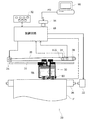
図5は、プリンタ20の概略構成図である。プリンタ20は、紙送りモータ22によって印刷用紙Pを副走査方向に搬送する副走査送り機構と、キャリッジモータ24によってキャリッジ30をプラテン26の軸方向(主走査方向)に往復動させる主走査送り機構と、キャリッジ30に搭載された印刷ヘッドユニット60を駆動してインクの吐出およびドット形成を制御するヘッド駆動機構と、これらの紙送りモータ22,キャリッジモータ24,印刷ヘッドユニット60および操作パネル32との信号のやり取りを司る制御回路40とを備えている。制御回路40は、コネクタ56を介してコンピュータ90に接続されている。
【0038】
印刷用紙Pを搬送する副走査送り機構は、紙送りモータ22の回転をプラテン26と用紙搬送ローラ(図示せず)とに伝達するギヤトレインを備える(図示省略)。また、キャリッジ30を往復動させる主走査送り機構は、プラテン26の軸と並行に架設されキャリッジ30を摺動可能に保持する摺動軸34と、キャリッジモータ24との間に無端の駆動ベルト36を張設するプーリ38と、キャリッジ30の原点位置を検出する位置センサ39とを備えている。
【0039】
図6は、制御回路40を中心としたプリンタ20の構成を示すブロック図である。制御回路40は、CPU41と、プログラマブルROM(PROM)43と、RAM44と、文字のドットマトリクスを記憶したキャラクタジェネレータ(CG)45とを備えた算術論理演算回路として構成されている。この制御回路40は、さらに、外部のモータ等とのインタフェースを専用に行なうI/F専用回路50と、このI/F専用回路50に接続され印刷ヘッドユニット60を駆動してインクを吐出させるヘッド駆動回路52と、紙送りモータ22およびキャリッジモータ24を駆動するモータ駆動回路54と、を備えている。I/F専用回路50は、パラレルインタフェース回路を内蔵しており、コネクタ56を介してコンピュータ90から供給される印刷データPDを受け取ることができる。プリンタ20は、この印刷データPDに従って印刷を実行する。なお、RAM44は、ラスタデータを一時的に格納するためのバッファメモリとして機能する。
【0040】
印刷ヘッドユニット60は、印刷ヘッド28を有しており、また、インクカートリッジを搭載可能である。なお、印刷ヘッドユニット60は、1つの部品としてプリンタ20に着脱される。すなわち、印刷ヘッド28を交換しようとする際には、印刷ヘッドユニット60を交換することになる。
【0041】
図7は、印刷ヘッド28の下面におけるノズル配列を示す説明図である。印刷ヘッド28の下面には、ブラックインクKを吐出するためのノズル群と、濃シアンインクCを吐出するためのノズル群と、淡シアンインクLCを吐出するためのノズル群と、濃マゼンタインクMを吐出するためのノズル群と、淡マゼンタインクLMを吐出するためのノズル群と、イエローインクYを吐出するためのノズル群とが形成されている。
【0042】
本実施例において、濃シアンインクCと濃マゼンタインクMとイエローインクYは、ほぼ等量混合することによってブラック(コンポジットブラック)を再現する。換言すれば、濃シアンインクCと濃マゼンタインクMとイエローインクYのドットをほぼ同じ数だけ形成することによって、コンポジットブラックを再現できる。また、淡シアンインクLCと淡マゼンタインクLMは、濃シアンインクCと濃マゼンタインクMの2/5の濃度をそれぞれ有している。従って、淡シアンインクLCと淡マゼンタインクLMとイエローインクYのドットを5:5:2の割合で形成しても、コンポジットブラックが得られる。
【0043】
なお、本明細書において、「シアンの1次色インク」という用語は、濃シアンインクCと淡シアンインクLCの双方を含んでいる。同様に、「マゼンタの1次色インク」という用語は、濃マゼンタインクMと淡マゼンタインクLMの双方を含んでいる。また、「シアンとマゼンタとイエローのいずれかの色相を有する有彩1次色インク」とい用語は、これらの3つの色相のいずれかを有し、濃度の異なるインクのすべてを含んでいる。
【0044】
以上説明したハードウェア構成を有するプリンタ20は、紙送りモータ22により用紙Pを搬送しつつ、キャリッジ30をキャリッジモータ24により往復動させ、同時に印刷ヘッド28のピエゾ素子を駆動して、各色インク滴の吐出を行い、インクドットを形成して用紙P上に多色多階調の画像を形成する。
【0045】
B.色再現の実施例:
図8は、実施例における色再現の処理手順を示すフローチャートである。ステップS1〜S7では、グレー色の好ましい色再現を行うための色変換ルックアップテーブルLUT(図4)を作成している。
【0046】
まず、ステップS1では、印刷で使用する印刷媒体とインクセットとの組合せを1つ選択する。通常のプリンタでは、複数種類の印刷媒体(普通紙、光沢紙、マット紙など)の中から、ユーザによって選択された1つの印刷媒体を使用することを想定している。また、ある種のプリンタでは、使用するインクセットを、複数種類のインクセット(例えば染料インクセットと顔料インクセット)の中から選択できる場合がある。印刷物の分光反射率は、印刷媒体とインクセットの分光特性に依存する。そこで、本実施例では、印刷媒体とインクセットの組合せ毎にステップS2〜S6の処理を実行して、その組合せに適した色変換ルックアップテーブルLUTをそれぞれ作成する。なお、プリンタ20において使用が想定されている印刷媒体の種類やインクセットの種類は、プリンタドライバ96の印刷条件設定のための画面(図示せず)に表示されるのが普通である。
【0047】
ステップS2では、複数種類のグレーカラーパッチを作成する。図9は、本実施例において作成されるグレーカラーパッチの種類を示す説明図である。図9の左上端に原点Oが取られており、縦軸はブラックインクKのインク量(%)、横軸はコンポジットブラックを構成するCMYの1色分の実効インク量(%)である。ここで、ブラックインクKのインク量は、ベタ領域における値を100%としている。また、「CMYの1色分の実効インク量」とは、コンポジットブラックが濃シアンインクCと濃マゼンタインクMとイエローインクYとを等量混合して得られるものとしたときの1色分のインク量を意味している。CMYの1色分の実効インク量が100%のときには、CMYの3色のインクが、1色でベタ領域を構成する場合のインク量だけそれぞれ吐出されていることを意味する。なお、本実施例では、淡シアンインクLCと淡マゼンタインクLMは、濃シアンインクCと濃マゼンタインクMの2/5の濃度をそれぞれ有している。例えば、淡シアンインクLCの10%は、濃シアンインクCの4%と等価であるものと見なされる。また、淡シアンインクLCを用いる場合の実際のインク量は、実効インク量の5/2倍である。なお、インク量は「ドット記録率」と呼ばれることもある。
【0048】
グレーカラーパッチとしては、図9の各矩形の位置で規定されるインク量を用いたものが作成される。なお、コンポジットブラックの実効インク量が比較的少ないとき(例えば実効インク量が12%以下のとき)には、濃シアンインクCと濃マゼンタインクMを使用せずに、淡シアンインクLCと淡マゼンタインクLMとを使用している。これは、同じ実効インク量を達成するためには濃インクよりも淡インクの方が実際のインク量が多いので、インクドットの数も多く、従って、画像の粒状性の低減の観点から淡インクの方が好ましいからである。なお、実効インク量が大きくなったとき(例えば14%以上のとき)には、濃インクの量が徐々に増加し、淡インクの量が徐々に減少する。
【0049】
なお、コンポジットブラックの実効インク量が0%のグレーカラーパッチは、ブラックインクKのみで再現されている。また、ブラックインクKのインク量が0%のグレーカラーパッチは、コンポジットブラックのみで再現されている。これら以外のグレーカラーパッチは、CMYKの4つの色相のインクを用いて再現されている。
【0050】
グレーカラーパッチの濃度(グレー階調レベル)は、原点Oから離れるほど高くなる傾向にある。従って、図9の各矩形で示されるグレーカラーパッチの中には、ほぼ同じ階調レベルを有するパッチが複数存在することがある。そこで、図8のステップS3以降の処理では、各階調レベルを有するグレーカラーパッチの中から、色の光源依存性と画像の粒状性の観点から好ましいものを選択する。
【0051】
ステップS3では、各グレーカラーパッチの分光反射率R(λ)が測定される。ステップS4では、各グレーカラーパッチに関して、標準光D50の下で観察したときの色と、標準光Aの下で観察したときの色の間の色差ΔEを算出する。具体的には、例えば、図2,図3に示したように、標準光D50の下で観察したとき三刺激値(X,Y,Z)D50 と、標準光Aの下で観察したときの三刺激値(X,Y,Z)A とを計算する。そして、これらの三刺激値(X,Y,Z)D50 ,(X,Y,Z)A からL*a*b*表色系の色差ΔEを算出する。
【0052】
図10は、グレーカラーパッチの色差ΔEの分布を示す説明図である。ここでは、グレーカラーパッチが色差ΔEに応じて複数のグループに分類されており、各グループ間の境界線が太線で示されている。一般に、コンポジットブラックのインク量が増加すると、色差ΔEが増大する傾向にある。また、色差ΔEが小さいほど色の光源依存性が小さく、グレー色以外の色味が混ざる程度が少ないので好ましい。また、画像の粒状性の観点からは、ブラックインクKのみを使用せずにコンポジットブラックを用いることが好ましい。特に、明度が比較的高い画像領域では、濃インクC,Mの代わりに淡インクLC,LMを用いることによって、粒状性をさらに改善することができる。
【0053】
図8のステップS6では、色差ΔEが所定のしきい値δ以下のパッチの中から、グレー色のグラデーションを再現する複数のパッチを選択する。図10には、こうして選択されたグレーカラーパッチの位置が黒丸で示されている。この例では、色差ΔEのしきい値δは3である。また、コンポジットブラックを構成する1色分の実効インク量が12%(合計36%)に達するまでは、同じグレー階調レベルの複数のパッチの中で、なるべくコンポジットブラックのインク量が多いものが選択されている。これは、ハイライト領域(高明度の領域)における粒状性とバンディングを改善するためである。
【0054】
なお、グレーカラーパッチの選択の軌跡は、図10に示したもの以外の種々のものを採用することが可能である。例えば、色差ΔEのしきい値δは、およそ4以下の任意の値を設定することが可能である。但し、しきい値δを1とすると、選択可能なグラーカラーパッチの数が極めて少なくなり、0%から100%までのグレー階調を再現するのは困難な場合がある。従って、しきい値δとしては、約2から約4の間の値が好ましい。特に、しきい値δを約4に設定すれば、グレーカラーパッチの選択の幅が広がるので、画像の粒状性を改善しやすいという利点がある。また、しきい値δを約2に設定すれば、色の光源依存性が小さくなるという点で好ましい。
【0055】
こうして種々のグレー階調レベルを再現するための複数のグレーカラーパッチが選択されると、図8のステップS6において、選択されたグレーカラーパッチを再現するための色変換ルックアップテーブルLUT(図4)が作成される。本実施例における色変換ルックアップテーブルLUTは、RGB画像データを入力とし、図7に示す6つのインク色のための多階調画像データを出力とするものである。そこで、色変換ルックアップテーブルLUTを作成する際には、まず、RGB画像データの値に応じたグレー階調レベルが算出される。次に、このグレー階調レベルを再現するためのグレーカラーパッチにおける各インクのインク量が、図10で選択されたパッチにおける値から決定される。そして、このRGB画像データの値を入力とし、各インクのインク量を出力とするルックアップテーブルLUTが作成される。なお、グレー色以外の色に関する入力と出力は、上述した方法以外の任意の方法で決定できる。
【0056】
図8のステップS7では、プリンタ20で使用が想定されている印刷媒体とインクセットのすべての組合せについてステップS1〜S6の処理が完了したか否かが判断される。すべての処理が完了していない場合には、ステップS1〜S6の処理が繰り返され、完了している場合には次のステップS8に移行する。
【0057】
ステップS8では、作成された複数種類の色変換ルックアップテーブルLUTがプリンタドライバ96(図4)に組み込まれる。プリンタドライバ96は、プリンタ20に供給される印刷データPDを作成する機能をコンピュータ90に実現させるためのコンピュータプログラムである。色変換ルックアップテーブルLUTは、プリンタドライバ96が参照するデータとして、プリンタドライバ96とともにコンピュータ90にインストールされる。なお、色変換ルックアップテーブルLUTが組み込まれたプリンタドライバ96は、通常は、プリンタ20の製造元によって供給される。
【0058】
図8のステップS9では、ユーザがプリンタ20を用いて印刷を実行する。この際、印刷媒体とインクセットのすべての組合せに関する色変換ルックアップテーブルLUTの中から、実際の印刷に使用する印刷媒体とインクセットの組に適したルックアップテーブルが選択されて、印刷が実行される。実際の印刷に使用する印刷媒体とインクセットの組は、プリンタドライバ96の印刷条件設定のための画面(図示せず)において、ユーザによって選択される。
【0059】
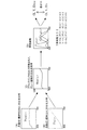
図11(A)は、本実施例で作成された色変換ルックアップテーブルLUTを用いてグレー色領域を再現する場合の各インクのインク量を示している。また、図11(B)は、比較例を示している。横軸は明度階調レベルであり、0〜255の範囲で定義されている。縦軸は、インク量(ドット記録率)である。なお、「ドット記録率」とは、1種類のインクによってベタ領域を印刷する場合を100%としたときの相対的なインク量を意味している。
【0060】
比較例では、明度が比較的高いとき(具体的には明度階調レベルが50/255以上のとき)にはブラックインクが使用されておらず、LC,LM,Yインクを用いたコンポジットブラックのみを用いてグレー色が再現されている。一方、実施例では、明度が比較的高いときにも、ブラックインクと、LC,LM,Yインクを用いたコンポジットブラックとの両方を用いてグレー色が再現されている。この結果、実施例では、比較例に比べて色の光源依存性が改善されている。また、淡インクLC,LMを用いたコンポジットブラックが用いられているので、濃インクC,Mを用いると仮定した場合よりも粒状性が改善されている。一方、比較例では、明度階調が高いところ(明るい画像領域)において、ブラックインクを用いずにコンポジットブラックを用いているので、粒状性の点では実施例よりも優れている。
【0061】
なお、本実施例では、淡インクLC,LMは、濃インクC,Mの濃度の2/5なので、LC,LM,Yインクを用いてコンポジットブラックを構成するときには、淡インクLC,LMのインク量は濃インクC,Mを用いるときの5/2倍となる。従って、淡インクLC,LMのインク量は、イエローインクYの5/2倍に設定されている。
【0062】
また、比較例では、明度階調レベルが255から次第に低下していくとLC,LMインクの量が増加してゆき、明度階調レベルが約140のときにLC,LM,Yインクによるコンポジットブラック関するデューティ制限値に達している。ここで、「デューティ制限値」とは、インクの滲みの観点から許容される最大のインク量を意味する。より具体的に言えば、あるインクの組合せに対するデューティ制限値は、そのインクの組合せを用いて印刷を行ったときに、滲みが発生しない量として決定される。
【0063】
図12は、インクの組合せに関するデューティ制限値を決定するために使用されるテストパターンの一例を示している。このテストパターンは、背景領域BGと、線状部LNと、文字部LTとを有している。例えば、背景領域BGは、LC,LM,Yインクによるコンポジットブラックを用いて印刷される。また、線状部LNと文字部LTは、それ以外の種々の色および濃度で印刷される。但し、通常は、線状部LNと文字部LTのインク量の合計値が、背景領域BGと同じ値に設定される。図12(A)では滲みは無いが、図12(B)では背景領域BGと線状部LNとの境界に滲みが見られる。このようなテストパターンは、種々のインク量について作成される。そして、滲みの出ない最大のインク量がデューティ制限値として決定される。
【0064】
図11(B)の比較例では、このようにして決定されたコンポジットブラック(LC,LM,Y)に関するデューティ制限値に達するまで淡インクLC,LMを増加させることが許容されている。一方、図11(A)に示す実施例では、淡インクLC,LMのインク量は、デューティ制限値からかなりの余裕がある。この理由は、明度が比較的高いときにも、コンポジットブラックのみでなく、ブラックインクKを積極的に使用することによって、色の光源依存性を改善しているからである。すなわち、本実施例では、インクのデューティ制限値の範囲内においてコンポジットブラックのみでグレー色を再現できる場合にも、ブラックインクKを利用することによって、コンポジットブラックを構成するインクLC,LM,Yのインク量を減少させている。
【0065】
より具体的に言えば、本実施例では、明度階調レベルが約150/255においてブラックインクKが使用されているのに対して、比較例では明度階調レベルが約50/255にまで低下したときに初めてブラックインクKが使用され始める。この例から理解できるように、色の光源依存性を改善するためには、明度階調レベルが約150/255以下の比較的暗いグレー色を、ブラックインクKとコンポジットブラックの双方を用いて再現することが好ましい。
【0066】
以上のように、本実施例では、任意の階調レベルのグレー色を、2種類の標準光D50,Aの下での色差ΔEが所定のしきい値δ以下になるように再現しているので、グレー色に関する光源依存性が改善されている。また、比較的明度階調レベルの高いグレー色を、ブラックインクKとコンポジットブラックとの双方を利用して再現しているので、画像の粒状性が少ないグレー色領域を再現することが可能である。
【0067】
C.変形例:
なお、この発明は上記の実施例や実施形態に限られるものではなく、その要旨を逸脱しない範囲において種々の態様において実施することが可能であり、例えば次のような変形も可能である。
【0068】
C1.変形例1:
上記実施例では、シアンとマゼンタに関しては淡インクLC,LMを用いてコンポジットブラックを構成していたが、淡インクを用いずに、濃シアンインクCと濃マゼンタインクMを用いてコンポジットブラックを構成してもよい。但し、明度階調レベルが比較的高いときには、濃インクC,Mを用いずに淡インクLC,LMを用いることによって、画像の粒状性を改善することができる。具体的には、明度階調レベルが約70/255〜255/255の範囲のときに、濃インクC,Mを用いずに淡インクLC,LMを用いることが好ましく、また、約50/255〜255/255の範囲のときに淡インクLC,LMを用いることが更に好ましい。
【0069】
C2.変形例2:
上記実施例では、グレー色の再現方法についてのみ説明したが、グレー色以外の色を再現する際にグレー成分が必要な場合にも本発明を適用可能である。すなわち、任意の色のグレー成分として、ブラックインクとコンポジットブラックの双方を用いることが可能である。但し、この場合に、グレー色に近い一定の色再現範囲にのみ、ブラックインクとコンポジットブラックの双方を用いるようにしてもよい。具体的には、例えば、L*a*b*表色系において、L*軸から一定の距離にある色のみに関してブラックインクとコンポジットブラックの双方を用い、他の色に関してはコンポジットブラックのみを用いてもよい。この理由は、グレー色以外の色は、人間の眼は色の光源依存性(メタメリズム)に比較的鈍感なので、色の光源依存性よりも粒状性を重視した方が好ましいからである。
【0070】
C3.変形例3:
上記実施例では、図9に示すように、グレーカラーパッチとして、ブラックインクのみで再現されたものと、コンポジットブラックのみで再現されたものと、ブラックインクおよびコンポジットブラックの混合で再現されたものと、の3種類のグラーカラーパッチを作成していた。しかし、ブラックインクのみでグレー色を再現することが無い場合には、ブラックインクのみで印刷されたグレーカラーパッチは作成する必要は無い。
【0071】
C4.変形例4:
上記実施例では、色変換ルックアップテーブルLUTは、RGBデータを入力とし、複数のインクの多階調データを出力としていたが、ルックアップテーブルLUTの入力の表色系としては、RGB表色系以外の任意の表色系(例えばXYZ表色系やL*a*b*表色系)を適用することが可能である。
【0072】
また、上記実施例では、プリンタ20のインクセットとして、6種類のインクを含むものを用いていたが、インクセットとしてはこれ以外の種々の構成を利用可能である。色変換ルックアップテーブルLUTは、プリンタ20において実際に利用されるインクセットに含まれている複数種類のインクのための多階調データ(第2の画像データ)を出力するように構成される。
【0073】
C5.変形例5:
上記実施例では、プリンタ20において使用することが想定されている複数種類の印刷媒体と、複数種類のインクセットのすべての組合せに関して、色の光源依存性と画像の粒状性のバランスを考慮して色変換ルックアップテーブルLUTが作成されていた。しかし、色の光源依存性と画像の粒状性のバランスを考慮した色変換ルックアップテーブルLUTは、これらの複数の組合せの一部についてのみ作成するようにしてもよい。具体的には、例えば、透明な印刷媒体(OHPなど)のためのルックアップテーブルLUTについては、色の光源依存性を考慮しなくてもよい。具体的には、図11(B)に示す比較例のように、かなり暗いグレー色もコンポジットブラックのみで再現するようにしてもよい。
【0074】
また、プリンタ20が複数の印刷解像度で印刷が可能な場合には、色の光源依存性と画像の粒状性のバランスは、その一部の印刷解像度でのみ考慮されていればよい。色の光源依存性と画像の粒状性のバランスは、高画質な印刷モードで特に要求されることが多く、高画質な印刷モードでは一般に印刷解像度が高い。従って、色の光源依存性と画像の粒状性のバランスを考慮したグレー色の再現は、印刷解像度が比較的高い少なくとも1つの印刷モードにおいて達成されていれば良い。
【0075】
なお、プリンタ20の少なくとも1つの印刷モードにおいて、色の光源依存性に比較的優れた第1の色変換ルックアップテーブルと、画像の粒状性に比較的優れた第1の色変換ルックアップテーブルとを少なくとも含む複数のテーブルから、ユーザが任意に選択できるよにしてもよい。例えば、第1の色変換ルックアップテーブルとして図11(A)に示した色再現を行うものを用い、第2の色変換ルックアップテーブルとして図11(B)に示した色再現を行うものを用いることができる。このとき、例えば、粒状性に優れた色変換ルックアップテーブルをデフォールト(初期設定)としておき、ユーザがプリンタドライバの印刷条件の詳細設定画面において、色の光源依存性に優れた色変換ルックアップテーブルを選択できるようにしてもよい。このようにすれば、ユーザの好みや画像の用途に応じた適切な画質(色の光源依存性や粒状性)を得ることが可能である。
【0076】
C6.変形例6:
上記実施例では、色変換ルックアップテーブルLUTを用いて印刷を行っていたが、本発明は、このような色変換ルックアップテーブルを使用しない印刷方法や印刷装置にも適用可能である。
【0077】
C7.変形例7:
この発明はドラムスキャンプリンタにも適用可能である。この発明は、いわゆるインクジェットプリンタのみでなく、一般に、印刷ヘッドからインクを吐出することによってカラー画像を印刷する印刷装置に適用することができる。このような印刷装置としては、例えばファクシミリ装置や、コピー装置などがある。
【0078】
C8.変形例8:
上記実施例において、ハードウェアによって実現されていた構成の一部をソフトウェアに置き換えるようにしてもよく、逆に、ソフトウェアによって実現されていた構成の一部をハードウェアに置き換えるようにしてもよい。例えば、プリンタドライバ96(図4)の機能の一部を、プリンタ20内の制御回路40(図6)が実行するようにすることも可能である。
【図面の簡単な説明】
【図1】ブラックインクのみで再現されたグレー色領域と、コンポジットブラックで再現されたグレー色領域とを拡大して示す説明図。
【図2】コンポジットブラックによるグレー色の色再現の原理を示す説明図。
【図3】ブラックインクのみによるグレー色の色再現の原理を示す説明図。
【図4】本発明の一実施例として印刷システムの構成を示すブロック図。
【図5】プリンタの構成を示す説明図。
【図6】プリンタ20における制御回路40の構成を示すブロック図。
【図7】印刷ヘッド28の下面におけるノズル配列を示す説明図。
【図8】実施例における色再現の処理手順を示すフローチャート。
【図9】本実施例において作成されるグレーカラーパッチの種類を示す説明図。
【図10】グレーカラーパッチの色差ΔEの分布を示す説明図。
【図11】実施例と比較例においてグレー色領域を再現する場合のインク量を示す説明図。
【図12】インクの組合せに関するデューティ制限値を決定するために使用されるテストパターンの一例を示す説明図。
【符号の説明】
20…カラープリンタ
21…CRT
22…紙送りモータ
24…キャリッジモータ
26…プラテン
28…印刷ヘッド
30…キャリッジ
32…操作パネル
34…摺動軸
36…駆動ベルト
38…プーリ
39…位置センサ
40…制御回路
41…CPU
44…RAM
50…I/F専用回路
52…ヘッド駆動回路
54…モータ駆動回路
56…コネクタ
60…印刷ヘッドユニット
90…コンピュータ
91…ビデオドライバ
95…アプリケーションプログラム
96…プリンタドライバ
97…解像度変換モジュール
98…色変換モジュール
99…ハーフトーンモジュール
100…ラスタライザ
LUT…色変換ルックアップテーブル[0001]
BACKGROUND OF THE INVENTION
The present invention relates to a color printing technique using a plurality of types of ink.
[0002]
[Prior art]
In recent years, color ink jet printers have been widely used as computer output devices. A normal color inkjet printer uses black (K) ink and a plurality of types of primary color inks having a hue of cyan C, magenta M, or yellow Y. Any color of the color image can be reproduced using these plural types of ink. In particular, the gray color can be reproduced using only black ink, or can be reproduced using three types of primary color inks of CMY. The gray color reproduced using the three primary color inks of CMY is generally called “composite black”.
[0003]
By the way, as one of the evaluation items of the image quality, there is so-called graininess (roughness of the image). Image graininess is observed when ink dots are formed in isolation. Therefore, the graininess of an image often becomes a problem in an image area having a relatively high brightness and a small number of ink dots.
[0004]
FIG. 1 is an explanatory diagram showing, in an enlarged manner, a gray color region reproduced only with black ink and a gray color region reproduced with composite black. As can be understood from this example, when a gray color is reproduced using composite black, the number of ink dots is three times that when only black ink is used. In general, the granularity of an image is more conspicuous as the number of ink dots is smaller. Therefore, from the viewpoint of image graininess, it is preferable to reproduce a gray color using composite black as much as possible.
[0005]
[Problems to be solved by the invention]
However, when a gray color reproduced using composite black is observed, it may appear to include a color other than gray. As will be described below, this phenomenon is mainly due to the influence of the spectral characteristics of the illumination light.
[0006]
FIG. 2 is an explanatory diagram showing the principle of gray color reproduction by composite black. 2A and 2B show the spectral distribution P of sunlight. D50 (Λ) and spectral distribution P of incandescent lamp A (Λ) is shown respectively. FIG. 2C shows a gray spectral reflectance R reproduced using composite black. CB FIG. 2D shows the color matching functions x (λ), y (λ), and z (λ) of the CIEXYZ color system. As is well known, the tristimulus values X, Y, Z representing the color of the image area are the spectral distribution P (λ) of the illumination light, the spectral reflectance R (λ) of the image area, and the color matching function. It is obtained by integrating the product of x (λ), y (λ) and z (λ) over the visible light range of wavelength λ. In this specification, the spectral distribution of the CIE standard light D50 is used as the spectral distribution of sunlight. The spectral distribution of CIE standard light A is used as the spectral distribution of the incandescent lamp.
[0007]
FIG. 3 is an explanatory diagram showing the principle of gray color reproduction using only black ink. As can be understood by comparing FIG. 2C and FIG. 3C, the spectral reflectance R of the composite black CB (Λ) is relatively rich in unevenness, and the spectral reflectance R of the black ink BK (Λ) is relatively flat. The spectral reflectance of the black ink and the spectral reflectance of the composite black are quite different from each other. For example, when observed under sunlight (standard light D50), the two appear to be almost the same color. The phenomenon in which two colors having different spectral characteristics appear to be the same color with the naked eye under a certain light source is called “metamerism (conditional equal color)”.
[0008]
However, when observed under illumination light other than sunlight (for example, an incandescent lamp), the gray color printed with composite black may appear to contain a color other than gray. This is because there is a large difference in spectral reflectance R (λ) between composite black and black ink. That is, for composite black, the spectral distribution P of sunlight D50 Tristimulus values (X, Y, Z) when using (λ) D50 And the spectral distribution P of the incandescent lamp A Tristimulus values (X, Y, Z) when using (λ) DA The difference with is relatively large. As a result, the gray color printed with composite black appears to include a color other than gray under an incandescent lamp. On the other hand, since the spectral reflectance of black ink is relatively flat, tristimulus values (X, Y, Z) D50 , (X, Y, Z) DA The difference is relatively small. As a result, the gray color printed with black ink appears gray when viewed under an incandescent lamp.
[0009]
It is not preferable that the color appearance by the naked eye depends on the illumination light as in the case of the composite black, and it is desirable that the same color be seen as much as possible even under different illumination light, that is, the color light source dependency is small. From the viewpoint of suppressing the light source dependency of the color, it is preferable to reproduce the gray color using black ink as much as possible.
[0010]
However, conventionally, when reproducing gray color, the light source dependency of the color has not been considered much.
[0011]
The present invention has been made to solve the above-described problems in the prior art, and an object of the present invention is to provide a technique capable of performing printing while suppressing light source dependency on gray color.
[0012]
[Means for solving the problems and their functions and effects]
In order to solve at least a part of the above-described problems, a first method of the present invention is a method for performing printing on a print medium using a printing apparatus capable of using a plurality of types of inks. A step of preparing a plurality of kinds of chromatic primary color inks each having a hue of cyan, magenta, or yellow, and a black ink; and (b) when printing a gray color region having an arbitrary gradation level. In addition, the plurality of types are selected so that the value of the color difference ΔE in the L * a * b * color system of the gray color region when the observation is performed under the standard light D50 and the standard light A is about 4 or less. A step of reproducing the gray color region using at least one of the chromatic primary color ink and the black ink.
[0013]
According to this printing method, since the gray color is reproduced so that the color difference ΔE is about 4 or less, printing can be performed while suppressing the light source dependency of the gray color.
[0014]
The second method of the present invention performs printing using a printing apparatus that can use an ink set including a plurality of types of chromatic primary color inks each having a hue of cyan, magenta, or yellow, and a black ink. A method for performing printing on a medium, wherein (a) first color image data represented by a first color system is represented by a second color system represented by a second color system for the ink set. (B) preparing the first color image data as the second color image data by using the color conversion lookup table; A step of converting, (c) generating print data representing an ink dot formation state in each pixel based on the second color image data, and (d) executing printing according to the print data. Includes a degree, the. When the first color image data represents a gray color region having an arbitrary gradation level, the color conversion lookup table assumes that the gray color is assumed to be observed under the standard light D50 and the standard light A. One or more types of the chromatic primary color ink and the black ink are used so that the value of the color difference ΔE in the L * a * b * color system of the region is about 4 or less. And having a gray reproduction characteristic for reproducing the gray color region.
[0015]
Also by this printing method, the gray color is reproduced so that the color difference ΔE is about 4 or less, so that it is possible to perform printing while suppressing the light source dependency of the gray color.
[0016]
In the first or second method, the first type gray color obtained by using the plurality of types of chromatic primary color inks, the black ink, and the plurality of types of chromatic primary color inks. It is preferable that the gray color region is reproduced by selecting any one of the second types of gray colors obtained by using.
[0017]
According to this configuration, the gray color is not reproduced only by the black ink, and the gray color is reproduced by using so-called composite black or both black ink and composite black. Accordingly, it is possible to reproduce a gray color region in which the light source dependency of the color and the graininess of the image are balanced.
[0018]
When the plurality of types of chromatic primary color inks include dark ink and light ink for cyan and magenta, respectively, and the lightness gradation level of the gray color region is in the range of about 70/255 to 255/255 For the cyan and magenta, it is preferable that the gray color region is reproduced using the light ink without using the dark ink.
[0019]
According to this configuration, there is an advantage that the graininess of the image is improved because the number of ink dots increases when the light ink is used rather than the dark ink.
[0020]
As the color conversion lookup table, each of the color conversion lookup tables each having gray reproduction characteristics suitable for at least two types of print media among a plurality of types of print media assumed to be used by the printing apparatus. You may make it prepare. At this time, the color conversion lookup table is selected according to the type of print medium actually used for printing.
[0021]
According to this configuration, since an appropriate color conversion lookup table corresponding to the type of print medium is selected, a high-quality gray color area corresponding to the print medium can be reproduced.
[0022]
Further, when the printing apparatus assumes use of a plurality of types of print media and assumes use of a plurality of types of ink sets having different spectral reflectance characteristics, the plurality of types are used as a color conversion lookup table. A color conversion lookup table having the gray reproduction characteristics is prepared for each of combinations of at least two types of print media and the plurality of types of ink sets. At this time, the color conversion lookup table is selected according to the combination of the type of printing medium actually used for printing and the ink set.
[0023]
According to this configuration, since an appropriate color conversion lookup table corresponding to the combination of the print medium and the ink set is selected, a high-quality gray color area corresponding to the combination of the print medium and the ink set can be reproduced. Is possible.
[0024]
According to a third method of the present invention, the first color image data represented by the first color system is converted into a plurality of types of chromatic primary color inks each having a hue of cyan, magenta, or yellow. A color conversion lookup table for converting to second color image data represented in a second color system for an ink set including black ink, comprising: (a) a plurality of color conversion lookup tables; For each gray gradation level, a first type gray color patch printed using the plurality of types of chromatic primary color inks, the black ink, and the plurality of types of chromatic primary color inks. A step of preparing a plurality of gray color patches including the second type of gray color patch printed by using, and (b) a gray color patch used for reproducing each gray gradation level as a standard One of the plurality of gray color patches is adjusted so that the value of the color difference ΔE in the L * a * b * color system when assumed to be observed under D50 and the standard light A is about 4 or less. And (c) determining the input and output of the color conversion lookup table so as to reproduce the gray color patch selected at each gray gradation level.
[0025]
A fourth method of the present invention is a method for printing on a print medium using a printing apparatus capable of using a plurality of types of ink, and (a) a hue of any one of cyan, magenta, and yellow A step of preparing a plurality of types of chromatic primary color inks and black inks each having the following: (b) when printing a relatively dark gray color region having a lightness gradation level of about 150/255 or less; Regenerating the gray color region using both the black ink and the plurality of types of chromatic primary color inks.
[0026]
In this fourth method, a relatively dark gray color region is reproduced using both so-called composite black and black ink, so that the balance between color light source dependency and image graininess is balanced. It is possible to reproduce a gray color area.
[0027]
According to a fifth method of the present invention, printing is performed using a printing apparatus capable of using an ink set including a plurality of types of chromatic primary color inks each having a hue of cyan, magenta, or yellow and a black ink. A method for performing printing on a medium, wherein (a) first color image data represented by a first color system is represented by a second color system represented by a second color system for the ink set. As a color conversion look-up table for conversion to color
(D) a step of executing printing according to the print data.
[0028]
In this method, printing is performed by selectively using a first color conversion lookup table that is relatively excellent in color light source dependency and a second color conversion lookup table that is relatively excellent in image graininess. Therefore, it is possible to obtain an appropriate image quality according to the user's preference and the use of the image.
[0029]
Specific embodiments of the present invention include a printing apparatus and a printing method, a color conversion method and apparatus, a color conversion lookup table creation method and apparatus, a computer program for realizing the functions of these apparatuses or methods, Various modes such as a computer-readable recording medium storing the computer program and a data signal including the computer program and embodied in a carrier wave can be used.
[0030]
DETAILED DESCRIPTION OF THE INVENTION
Next, embodiments of the present invention will be described in the following order based on examples.
A. Device configuration:
B. Examples of color reproduction:
C. Variations:
[0031]
A. Device configuration:
FIG. 4 is a block diagram showing the configuration of a printing system as an embodiment of the present invention. This printing system includes a
[0032]
In the
[0033]
When the
[0034]
The
[0035]
The color-converted multi-gradation data has, for example, 256 gradation values. The
[0036]
The
[0037]
FIG. 5 is a schematic configuration diagram of the
[0038]
The sub-scan feed mechanism for transporting the printing paper P includes a gear train (not shown) that transmits the rotation of the
[0039]
FIG. 6 is a block diagram showing the configuration of the
[0040]
The
[0041]
FIG. 7 is an explanatory diagram showing the nozzle arrangement on the lower surface of the
[0042]
In this embodiment, dark cyan ink C, dark magenta ink M, and yellow ink Y reproduce black (composite black) by mixing substantially equal amounts. In other words, by forming approximately the same number of dots of dark cyan ink C, dark magenta ink M, and yellow ink Y, composite black can be reproduced. Further, the light cyan ink LC and the light magenta ink LM have a density of 2/5 of the dark cyan ink C and the dark magenta ink M, respectively. Accordingly, even if the dots of the light cyan ink LC, the light magenta ink LM, and the yellow ink Y are formed at a ratio of 5: 5: 2, composite black can be obtained.
[0043]
In this specification, the term “cyan primary color ink” includes both the dark cyan ink C and the light cyan ink LC. Similarly, the term “magenta primary color ink” includes both dark magenta ink M and light magenta ink LM. Further, the term “chromatic primary color ink having a hue of cyan, magenta, or yellow” includes any of these three hues and inks having different densities.
[0044]
In the
[0045]
B. Examples of color reproduction:
FIG. 8 is a flowchart illustrating a color reproduction processing procedure in the embodiment. In steps S1 to S7, a color conversion look-up table LUT (FIG. 4) for creating a preferable gray color is created.
[0046]
First, in step S1, one combination of a print medium and an ink set used for printing is selected. In a normal printer, it is assumed that one print medium selected by the user from a plurality of types of print media (plain paper, glossy paper, matte paper, etc.) is used. In some types of printers, the ink set to be used may be selected from a plurality of types of ink sets (for example, a dye ink set and a pigment ink set). The spectral reflectance of the printed material depends on the spectral characteristics of the print medium and the ink set. Therefore, in this embodiment, the processing of steps S2 to S6 is executed for each combination of the print medium and the ink set, and a color conversion lookup table LUT suitable for the combination is created. Note that the type of print medium and the type of ink set that are assumed to be used in the
[0047]
In step S2, a plurality of types of gray color patches are created. FIG. 9 is an explanatory diagram showing the types of gray color patches created in this embodiment. The origin O is taken at the upper left corner of FIG. 9, the vertical axis represents the ink amount (%) of the black ink K, and the horizontal axis represents the effective ink amount (%) for one color of CMY constituting the composite black. Here, the ink amount of the black ink K is 100% in the solid area. The “effective amount of ink for one color of CMY” means that the composite black is obtained by mixing dark cyan ink C, dark magenta ink M, and yellow ink Y in equal amounts. This means the amount of ink. When the effective ink amount for one color of CMY is 100%, it means that the three colors of CMY are ejected by the amount of ink when one color forms a solid area. In this embodiment, the light cyan ink LC and the light magenta ink LM have a density of 2/5 of the dark cyan ink C and the dark magenta ink M, respectively. For example, 10% of light cyan ink LC is considered equivalent to 4% of dark cyan ink C. The actual ink amount when the light cyan ink LC is used is 5/2 times the effective ink amount. The ink amount is sometimes called “dot recording rate”.
[0048]
As the gray color patch, a patch using the ink amount defined at the position of each rectangle in FIG. 9 is created. When the effective ink amount of composite black is relatively small (for example, when the effective ink amount is 12% or less), the light cyan ink LC and the light magenta are used without using the dark cyan ink C and the dark magenta ink M. Ink LM is used. This is because, in order to achieve the same effective ink amount, the light ink has a larger amount of ink than the dark ink, so the number of ink dots is also large. Therefore, from the viewpoint of reducing the graininess of the image, the light ink This is because it is preferable. When the effective ink amount becomes large (for example, 14% or more), the dark ink amount gradually increases and the light ink amount gradually decreases.
[0049]
Note that a gray color patch with an effective ink amount of 0% for composite black is reproduced only with the black ink K. Further, the gray color patch in which the ink amount of the black ink K is 0% is reproduced only with composite black. The gray color patches other than these are reproduced using inks of four hues of CMYK.
[0050]
The density (gray gradation level) of the gray color patch tends to increase as the distance from the origin O increases. Accordingly, there may be a plurality of patches having substantially the same gradation level among the gray color patches indicated by the respective rectangles in FIG. Therefore, in the processing after step S3 in FIG. 8, a gray color patch having each gradation level is selected from the viewpoint of color light source dependency and image graininess.
[0051]
In step S3, the spectral reflectance R (λ) of each gray color patch is measured. In step S4, for each gray color patch, a color difference ΔE between the color observed under the standard light D50 and the color observed under the standard light A is calculated. Specifically, for example, as shown in FIGS. 2 and 3, tristimulus values (X, Y, Z) when observed under the standard light D50. D50 And tristimulus values (X, Y, Z) when observed under standard light A A And calculate. And these tristimulus values (X, Y, Z) D50 , (X, Y, Z) A To calculate the color difference ΔE of the L * a * b * color system.
[0052]
FIG. 10 is an explanatory diagram showing the distribution of the color difference ΔE of the gray color patch. Here, the gray color patches are classified into a plurality of groups according to the color difference ΔE, and the boundary lines between the groups are indicated by bold lines. Generally, as the amount of composite black ink increases, the color difference ΔE tends to increase. Further, the smaller the color difference ΔE, the smaller the dependency of the light source on the light source, and the less the color mixture other than the gray color is preferable. From the viewpoint of image graininess, it is preferable to use composite black instead of using only black ink K. In particular, in an image region having a relatively high brightness, the graininess can be further improved by using the light inks LC and LM instead of the dark inks C and M.
[0053]
In step S6 of FIG. 8, a plurality of patches that reproduce a gray gradation are selected from patches having a color difference ΔE of a predetermined threshold value δ or less. In FIG. 10, the positions of the gray color patches thus selected are indicated by black circles. In this example, the threshold value δ of the color difference ΔE is 3. Also, until the effective ink amount for one color composing the composite black reaches 12% (36% in total), among the patches having the same gray gradation level, the composite black ink amount is as large as possible. Is selected. This is to improve graininess and banding in the highlight area (high brightness area).
[0054]
It should be noted that various traces other than those shown in FIG. 10 can be adopted as the gray color patch selection locus. For example, the threshold value δ of the color difference ΔE can be set to an arbitrary value of about 4 or less. However, if the threshold value δ is 1, the number of selectable gray color patches is extremely small, and it may be difficult to reproduce a gray gradation from 0% to 100%. Accordingly, the threshold value δ is preferably a value between about 2 and about 4. In particular, if the threshold value δ is set to about 4, the selection range of the gray color patch is widened, so that there is an advantage that the graininess of the image can be easily improved. Setting the threshold value δ to about 2 is preferable in that the light source dependency of the color is reduced.
[0055]
When a plurality of gray color patches for reproducing various gray tone levels are selected in this way, in step S6 of FIG. 8, a color conversion lookup table LUT (FIG. 4) for reproducing the selected gray color patch is selected. ) Is created. The color conversion lookup table LUT in the present embodiment receives RGB image data and outputs multi-tone image data for the six ink colors shown in FIG. Therefore, when creating the color conversion lookup table LUT, first, the gray gradation level corresponding to the value of the RGB image data is calculated. Next, the ink amount of each ink in the gray color patch for reproducing this gray gradation level is determined from the value in the patch selected in FIG. Then, a look-up table LUT is created that takes the values of the RGB image data as input and outputs the ink amount of each ink. Note that inputs and outputs related to colors other than gray can be determined by any method other than the method described above.
[0056]
In step S7 in FIG. 8, it is determined whether or not the processing in steps S1 to S6 has been completed for all combinations of print media and ink sets that are assumed to be used in the
[0057]
In step S8, the created plural types of color conversion lookup tables LUT are incorporated in the printer driver 96 (FIG. 4). The
[0058]
In step S <b> 9 of FIG. 8, the user executes printing using the
[0059]
FIG. 11A shows the ink amount of each ink when the gray color region is reproduced using the color conversion lookup table LUT created in the present embodiment. FIG. 11B shows a comparative example. The horizontal axis represents the lightness gradation level, which is defined in the range of 0 to 255. The vertical axis represents the ink amount (dot recording rate). The “dot recording rate” means a relative ink amount when a solid area is printed with one type of ink as 100%.
[0060]
In the comparative example, when the lightness is relatively high (specifically, when the lightness gradation level is 50/255 or more), black ink is not used, and only composite black using LC, LM, and Y ink is used. The gray color is reproduced using. On the other hand, in the embodiment, even when the lightness is relatively high, the gray color is reproduced using both the black ink and the composite black using the LC, LM, and Y inks. As a result, the light source dependency of the color is improved in the example as compared with the comparative example. Further, since the composite black using the light inks LC and LM is used, the graininess is improved as compared with the case where the dark inks C and M are used. On the other hand, in the comparative example, since the composite black is used without using the black ink in a place where the lightness gradation is high (bright image region), it is superior to the embodiment in terms of graininess.
[0061]
In this embodiment, since the light inks LC and LM are 2/5 of the dark inks C and M, when the composite black is formed using the LC, LM and Y inks, the light inks LC and LM inks are used. The amount is 5/2 times that when dark inks C and M are used. Therefore, the amount of light ink LC, LM is set to 5/2 times that of yellow ink Y.
[0062]
In the comparative example, when the lightness gradation level gradually decreases from 255, the amount of the LC and LM inks increases, and when the lightness gradation level is about 140, the composite black by LC, LM, and Y ink is used. The duty limit value is reached. Here, the “duty limit value” means the maximum amount of ink allowed from the viewpoint of ink bleeding. More specifically, the duty limit value for a certain ink combination is determined as an amount that does not cause bleeding when printing is performed using that ink combination.
[0063]
FIG. 12 shows an example of a test pattern used to determine the duty limit value for the ink combination. This test pattern has a background region BG, a linear portion LN, and a character portion LT. For example, the background region BG is printed using composite black using LC, LM, and Y ink. In addition, the linear portion LN and the character portion LT are printed in various other colors and densities. However, the total value of the ink amounts of the linear portion LN and the character portion LT is normally set to the same value as that of the background region BG. In FIG. 12A, there is no blur, but in FIG. 12B, blur is seen at the boundary between the background region BG and the linear portion LN. Such test patterns are created for various ink amounts. The maximum ink amount that does not cause bleeding is determined as the duty limit value.
[0064]
In the comparative example of FIG. 11B, the light ink LC, LM is allowed to increase until the duty limit value for the composite black (LC, LM, Y) determined in this way is reached. On the other hand, in the embodiment shown in FIG. 11A, the ink amount of the light ink LC, LM has a considerable margin from the duty limit value. This is because the light source dependency of the color is improved by positively using not only the composite black but also the black ink K even when the brightness is relatively high. That is, in this embodiment, even when a gray color can be reproduced only with composite black within the range of the ink duty limit value, by using the black ink K, the inks LC, LM, and Y constituting the composite black are used. The ink amount is decreased.
[0065]
More specifically, in this embodiment, the black color K is used at a lightness gradation level of about 150/255, whereas in the comparative example, the lightness gradation level is reduced to about 50/255. The black ink K begins to be used for the first time. As can be understood from this example, in order to improve the light source dependency of the color, a relatively dark gray color having a lightness gradation level of about 150/255 or less is reproduced using both the black ink K and the composite black. It is preferable to do.
[0066]
As described above, in this embodiment, a gray color having an arbitrary gradation level is reproduced so that the color difference ΔE under the two types of standard lights D50 and A is equal to or less than the predetermined threshold value δ. Thus, the light source dependency on gray color is improved. Further, since the gray color having a relatively high lightness gradation level is reproduced using both the black ink K and the composite black, it is possible to reproduce a gray color region with less image granularity. .
[0067]
C. Variations:
The present invention is not limited to the above-described examples and embodiments, and can be implemented in various modes without departing from the gist thereof. For example, the following modifications are possible.
[0068]
C1. Modification 1:
In the above-described embodiment, for black and magenta, the composite black is configured using the light inks LC and LM. However, the composite black is configured using the dark cyan ink C and the dark magenta ink M without using the light ink. May be. However, when the lightness gradation level is relatively high, the granularity of the image can be improved by using the light inks LC and LM without using the dark inks C and M. Specifically, when the lightness gradation level is in the range of about 70/255 to 255/255, it is preferable to use the light inks LC and LM without using the dark inks C and M, and about 50/255. It is more preferable to use the light inks LC and LM in the range of ˜255 / 255.
[0069]
C2. Modification 2:
In the above embodiment, only the gray color reproduction method has been described. However, the present invention can also be applied to cases where a gray component is required when reproducing a color other than the gray color. That is, it is possible to use both black ink and composite black as the gray component of any color. In this case, however, both black ink and composite black may be used only in a certain color reproduction range close to gray. Specifically, for example, in the L * a * b * color system, both black ink and composite black are used only for colors that are a fixed distance from the L * axis, and only composite black is used for other colors. May be. The reason for this is that colors other than gray are relatively insensitive to the light source dependency (metamerism) of the color, and therefore it is preferable to place importance on the graininess rather than the light source dependency of the color.
[0070]
C3. Modification 3:
In the above embodiment, as shown in FIG. 9, as gray color patches, those reproduced only with black ink, those reproduced only with composite black, and those reproduced with a mixture of black ink and composite black. The three types of Gura-color patches were created. However, when the gray color is not reproduced only with the black ink, it is not necessary to create a gray color patch printed only with the black ink.
[0071]
C4. Modification 4:
In the above-described embodiment, the color conversion lookup table LUT has RGB data as input and multi-tone data of a plurality of inks as output. Any color system other than (for example, XYZ color system or L * a * b * color system) can be applied.
[0072]
In the above embodiment, the ink set of the
[0073]
C5. Modification 5:
In the above-described embodiment, with respect to all combinations of a plurality of types of print media assumed to be used in the
[0074]
Further, when the
[0075]
Note that, in at least one print mode of the
[0076]
C6. Modification 6:
In the above embodiment, printing is performed using the color conversion lookup table LUT, but the present invention is also applicable to printing methods and printing apparatuses that do not use such a color conversion lookup table.
[0077]
C7. Modification 7:
The present invention is also applicable to a drum scan printer. The present invention can be applied not only to so-called inkjet printers but also to printing apparatuses that print color images by ejecting ink from a print head. Examples of such a printing apparatus include a facsimile machine and a copying machine.
[0078]
C8. Modification 8:
In the above embodiment, a part of the configuration realized by hardware may be replaced with software, and conversely, a part of the configuration realized by software may be replaced by hardware. For example, a part of the function of the printer driver 96 (FIG. 4) can be executed by the control circuit 40 (FIG. 6) in the
[Brief description of the drawings]
FIG. 1 is an explanatory diagram showing, in an enlarged manner, a gray color region reproduced only with black ink and a gray color region reproduced with composite black.
FIG. 2 is an explanatory diagram illustrating the principle of gray color reproduction by composite black.
FIG. 3 is an explanatory diagram illustrating the principle of gray color reproduction using only black ink.
FIG. 4 is a block diagram showing the configuration of a printing system as an embodiment of the present invention.
FIG. 5 is an explanatory diagram illustrating a configuration of a printer.
6 is a block diagram showing a configuration of a
FIG. 7 is an explanatory diagram showing a nozzle arrangement on the lower surface of the print head.
FIG. 8 is a flowchart illustrating a color reproduction processing procedure in the embodiment.
FIG. 9 is an explanatory diagram showing types of gray color patches created in the present embodiment.
FIG. 10 is an explanatory diagram showing a distribution of a color difference ΔE of a gray color patch.
FIG. 11 is an explanatory diagram showing an ink amount when a gray color area is reproduced in an example and a comparative example.
FIG. 12 is an explanatory diagram showing an example of a test pattern used for determining a duty limit value related to an ink combination.
[Explanation of symbols]
20 Color printer
21 ... CRT
22 ... Paper feed motor
24 ... Carriage motor
26 ... Platen
28 ... Print head
30 ... carriage
32 ... Control panel
34 ... Sliding shaft
36 ... Drive belt
38 ... pulley
39 ... Position sensor
40 ... Control circuit
41 ... CPU
44 ... RAM
50 ... I / F dedicated circuit
52. Head drive circuit
54 ... Motor drive circuit
56 ... Connector
60 ... print head unit
90 ... Computer
91 ... Video driver
95 ... Application program
96 ... Printer driver
97 ... Resolution conversion module
98 ... Color conversion module
99 ... Halftone module
100 ... Rasterizer
LUT ... Color conversion lookup table
Claims (1)
(a)複数のグレー階調レベルのそれぞれに関して、前記複数種類の有彩1次色インクを用いて印刷を行った第1種のグレーカラーパッチと、前記ブラックインクと前記複数種類の有彩1次色インクとを用いて印刷を行った第2種のグレーカラーパッチと、を含む複数のグレーカラーパッチを準備する工程と、
(b)各グレー階調レベルを再現するために使用するグレーカラーパッチとして、標準光D50および標準光Aの下で観察すると仮定したときのL*a*b* 表色系での色差ΔEの値が4以下になるように、前記複数のグレーカラーパッチのうちの1つを選択する工程と、
(c)各グレー階調レベルにおいて選択されたグレーカラーパッチを再現するように前記色変換ルックアップテーブルの入力と出力を決定する工程と、
を備え、
前記工程(b)において、画像のハイライト領域では、同じグレー階調レベルの複数のグレーカラーパッチの中で、なるべくコンポジットブラックのインク量が多いものを選択する、色変換ルックアップテーブルの作成方法。The first color image data represented in the first color system is obtained from an ink set including a plurality of types of chromatic primary color inks each having a hue of cyan, magenta, or yellow, and a black ink. A method for creating a color conversion lookup table for converting to second color image data represented in a second color system for:
(A) For each of a plurality of gray gradation levels, the first type gray color patch printed using the plurality of types of chromatic primary color inks, the black ink, and the plurality of types of chromatic 1 A step of preparing a plurality of gray color patches including a second type of gray color patch printed using a secondary color ink;
(B) As a gray color patch used to reproduce each gray gradation level, the color difference ΔE in the L * a * b * color system when assumed to be observed under the standard light D50 and the standard light A Selecting one of the plurality of gray color patches such that the value is 4 or less;
(C) determining the input and output of the color conversion lookup table to reproduce the selected gray color patch at each gray tone level;
Equipped with a,
In the step (b), in the highlight area of the image, a method for creating a color conversion lookup table that selects a plurality of gray color patches having the same gray gradation level and having as much composite black ink as possible .
Priority Applications (6)
| Application Number | Priority Date | Filing Date | Title |
|---|---|---|---|
| JP2001143616A JP4038998B2 (en) | 2001-02-23 | 2001-05-14 | Printing with reduced color light source dependency |
| US10/081,244 US6637861B2 (en) | 2001-02-23 | 2002-02-21 | Reduction of dependence of color appearance on light source |
| EP02004041A EP1235423A3 (en) | 2001-02-23 | 2002-02-22 | Reduction of dependence of color appearance on light source |
| US10/655,140 US6851794B2 (en) | 2001-02-23 | 2003-09-03 | Reduction of dependence of color appearance on light source |
| US11/026,306 US7549717B2 (en) | 2001-02-23 | 2004-12-29 | Reduction of dependence of color appearance on light source |
| US12/454,964 US7883168B2 (en) | 2001-02-23 | 2009-05-26 | Reduction of dependence of color appearance on light source |
Applications Claiming Priority (3)
| Application Number | Priority Date | Filing Date | Title |
|---|---|---|---|
| JP2001047776 | 2001-02-23 | ||
| JP2001-47776 | 2001-02-23 | ||
| JP2001143616A JP4038998B2 (en) | 2001-02-23 | 2001-05-14 | Printing with reduced color light source dependency |
Publications (3)
| Publication Number | Publication Date |
|---|---|
| JP2002321396A JP2002321396A (en) | 2002-11-05 |
| JP2002321396A5 JP2002321396A5 (en) | 2005-04-07 |
| JP4038998B2 true JP4038998B2 (en) | 2008-01-30 |
Family
ID=26609956
Family Applications (1)
| Application Number | Title | Priority Date | Filing Date |
|---|---|---|---|
| JP2001143616A Expired - Fee Related JP4038998B2 (en) | 2001-02-23 | 2001-05-14 | Printing with reduced color light source dependency |
Country Status (3)
| Country | Link |
|---|---|
| US (4) | US6637861B2 (en) |
| EP (1) | EP1235423A3 (en) |
| JP (1) | JP4038998B2 (en) |
Families Citing this family (34)
| Publication number | Priority date | Publication date | Assignee | Title |
|---|---|---|---|---|
| US6820979B1 (en) * | 1999-04-23 | 2004-11-23 | Neuroptics, Inc. | Pupilometer with pupil irregularity detection, pupil tracking, and pupil response detection capability, glaucoma screening capability, intracranial pressure detection capability, and ocular aberration measurement capability |
| JP4218165B2 (en) * | 2000-01-19 | 2009-02-04 | ブラザー工業株式会社 | Image data conversion processing method and recording medium recording image data conversion processing program |
| JP4038998B2 (en) * | 2001-02-23 | 2008-01-30 | セイコーエプソン株式会社 | Printing with reduced color light source dependency |
| JP3831941B2 (en) * | 2001-03-07 | 2006-10-11 | セイコーエプソン株式会社 | Ink set and recording method and recorded matter using the same |
| EP1276314B1 (en) * | 2001-07-13 | 2007-11-14 | Hewlett-Packard Company | Spot color application in printer device |
| JP2004338098A (en) * | 2003-05-13 | 2004-12-02 | Seiko Epson Corp | Print dividing method based on characteristics of ink |
| US8537417B2 (en) * | 2003-09-25 | 2013-09-17 | Xerox Corporation | Method for improved printer characterization |
| US7706604B2 (en) * | 2003-11-03 | 2010-04-27 | Seiko Epson Corporation | Production of color conversion profile for printing |
| US7245763B2 (en) * | 2004-01-14 | 2007-07-17 | Xerox Corporation | Gray component replacement as part of marking process control algorithm |
| JP4263657B2 (en) * | 2004-05-11 | 2009-05-13 | 理想科学工業株式会社 | Image processing apparatus, image processing method, and printer driver |
| JP4492274B2 (en) * | 2004-09-24 | 2010-06-30 | セイコーエプソン株式会社 | Printing control apparatus, method, program, and recording medium |
| JP4768459B2 (en) * | 2005-05-17 | 2011-09-07 | 株式会社リコー | Image forming apparatus |
| JP2007030198A (en) * | 2005-07-22 | 2007-02-08 | Ricoh Co Ltd | Image forming method, program for executing image forming method and ink jet recorder |
| US7612915B2 (en) * | 2005-10-20 | 2009-11-03 | Hewlett-Packard Development Company, L.P. | Determining composite grays |
| JP2007181090A (en) * | 2005-12-28 | 2007-07-12 | Canon Marketing Japan Inc | Image forming apparatus, image forming method, program for executing the method, and color chart |
| US20070247647A1 (en) * | 2006-04-21 | 2007-10-25 | Daniel Pettigrew | 3D lut techniques for color correcting images |
| US7693341B2 (en) * | 2006-04-21 | 2010-04-06 | Apple Inc. | Workflows for color correcting images |
| US8022964B2 (en) | 2006-04-21 | 2011-09-20 | Apple Inc. | 3D histogram and other user interface elements for color correcting images |
| KR100909059B1 (en) | 2006-08-08 | 2009-07-23 | 캐논 가부시끼가이샤 | Information processing device, information processing method, and color separation table creation method |
| US8405868B2 (en) * | 2006-09-27 | 2013-03-26 | Andrew Jackson | Method, apparatus and technique for enabling individuals to create and use color |
| US7889387B2 (en) * | 2006-12-22 | 2011-02-15 | Canon Kabushiki Kaisha | Construction of colorimetric measurements from device profile of spectral measurements |
| KR20090013673A (en) * | 2007-08-02 | 2009-02-05 | 삼성전자주식회사 | Ink jet image forming apparatus and control method thereof |
| JP5094433B2 (en) * | 2008-01-11 | 2012-12-12 | キヤノン株式会社 | Image processing apparatus and image processing method |
| JP5254674B2 (en) * | 2008-06-13 | 2013-08-07 | キヤノン株式会社 | Image processing method and image processing apparatus |
| US8085435B2 (en) * | 2008-10-24 | 2011-12-27 | Eastman Kodak Company | Adaptive color transform to control color inconstancy |
| JP5210145B2 (en) * | 2008-12-22 | 2013-06-12 | キヤノン株式会社 | Image processing method and image processing apparatus |
| JP5402178B2 (en) * | 2009-04-07 | 2014-01-29 | セイコーエプソン株式会社 | RECORDING CONTROL DEVICE, RECORDING SYSTEM, RECORDING CONTROL METHOD, AND PROGRAM |
| JP2011070320A (en) * | 2009-09-24 | 2011-04-07 | Seiko Epson Corp | Authentication system, printer terminal and authenticating person's terminal |
| US8564861B2 (en) * | 2010-11-30 | 2013-10-22 | Eastman Kodak Company | Providing calibration data for printer |
| JP5139507B2 (en) | 2010-12-10 | 2013-02-06 | キヤノン・コンポーネンツ株式会社 | Image sensor unit and image reading apparatus |
| JP5400188B2 (en) * | 2011-05-11 | 2014-01-29 | キヤノン・コンポーネンツ株式会社 | Image sensor unit and image reading apparatus and image forming apparatus using the same |
| JP5921120B2 (en) * | 2011-09-07 | 2016-05-24 | キヤノン株式会社 | Information processing apparatus and information processing method |
| JP6642047B2 (en) * | 2016-01-28 | 2020-02-05 | コニカミノルタ株式会社 | Image forming device |
| JP7314628B2 (en) * | 2019-06-05 | 2023-07-26 | セイコーエプソン株式会社 | Image processing device, image processing method, and image processing program |
Family Cites Families (22)
| Publication number | Priority date | Publication date | Assignee | Title |
|---|---|---|---|---|
| JPH04104575A (en) | 1990-08-24 | 1992-04-07 | Canon Inc | Color picture copying device |
| US5608549A (en) * | 1991-06-11 | 1997-03-04 | Canon Kabushiki Kaisha | Apparatus and method for processing a color image |
| US5377024A (en) * | 1992-05-04 | 1994-12-27 | Hewlett-Packard | Apparatus for forming color images using a hue-plus-gray color model |
| US5305119A (en) * | 1992-10-01 | 1994-04-19 | Xerox Corporation | Color printer calibration architecture |
| US6084604A (en) * | 1992-10-30 | 2000-07-04 | Canon Kabushiki Kaisha | Color ink jet recording method and apparatus using black ink and color-mixed black ink |
| JPH0795426A (en) | 1993-09-27 | 1995-04-07 | Toyo Ink Mfg Co Ltd | Device for color matching under different light sources |
| US5559604A (en) * | 1993-09-27 | 1996-09-24 | Toyo Ink Manufacturing Co., Ltd. | Color matching apparatus for reproducing the same color under different illuminants |
| JPH09321999A (en) * | 1996-05-24 | 1997-12-12 | Fuji Photo Film Co Ltd | Color conversion accuracy correction method |
| JPH1013697A (en) * | 1996-06-18 | 1998-01-16 | Canon Inc | Image processor and image processing method |
| JPH10173948A (en) | 1996-12-16 | 1998-06-26 | Fuji Photo Film Co Ltd | Color reproduction data conversion method |
| JPH10142775A (en) | 1996-11-15 | 1998-05-29 | Fuji Photo Film Co Ltd | Method for converting color reproduction data |
| JP3785775B2 (en) | 1997-12-05 | 2006-06-14 | セイコーエプソン株式会社 | Printing apparatus, image processing method, and recording medium storing program for realizing the method |
| US6567186B1 (en) * | 1998-10-27 | 2003-05-20 | Hewlett-Packard Company | Method for determining gray values in a printer |
| US6542259B1 (en) * | 1999-02-23 | 2003-04-01 | Hewlett-Packard Company | Imaging system with color corrected light source |
| US6859291B1 (en) * | 1999-03-30 | 2005-02-22 | Konica Corporation | Inkjet type color image processing apparatus for textile printing |
| JP2000345463A (en) | 1999-03-30 | 2000-12-12 | Konica Corp | Printing apparatus, printing data preparation apparatus and printing |
| US6690489B1 (en) * | 1999-12-02 | 2004-02-10 | Hewlett-Packard Development Company, L.P. | Color conversion acceleration using lookup tables |
| JP2001277552A (en) | 2000-03-29 | 2001-10-09 | Seiko Epson Corp | Printing control unit, printing control method, printer, and recording medium |
| JP2002247397A (en) | 2001-02-16 | 2002-08-30 | Fuji Photo Film Co Ltd | Method of reproducing color, digital color hard copying device using it, and program for executing it |
| JP4038998B2 (en) * | 2001-02-23 | 2008-01-30 | セイコーエプソン株式会社 | Printing with reduced color light source dependency |
| US6783203B2 (en) * | 2001-05-11 | 2004-08-31 | Seiko Epson Corporation | Printing with multiple pixels as unit of gradation reproduction |
| JP3713574B2 (en) * | 2001-05-29 | 2005-11-09 | コニカミノルタビジネステクノロジーズ株式会社 | Image processing apparatus, image processing method, and program |
-
2001
- 2001-05-14 JP JP2001143616A patent/JP4038998B2/en not_active Expired - Fee Related
-
2002
- 2002-02-21 US US10/081,244 patent/US6637861B2/en not_active Expired - Fee Related
- 2002-02-22 EP EP02004041A patent/EP1235423A3/en not_active Ceased
-
2003
- 2003-09-03 US US10/655,140 patent/US6851794B2/en not_active Expired - Fee Related
-
2004
- 2004-12-29 US US11/026,306 patent/US7549717B2/en not_active Expired - Fee Related
-
2009
- 2009-05-26 US US12/454,964 patent/US7883168B2/en not_active Expired - Fee Related
Also Published As
| Publication number | Publication date |
|---|---|
| EP1235423A3 (en) | 2005-08-31 |
| US7883168B2 (en) | 2011-02-08 |
| US6637861B2 (en) | 2003-10-28 |
| US20050111020A1 (en) | 2005-05-26 |
| US20090244156A1 (en) | 2009-10-01 |
| US20020158933A1 (en) | 2002-10-31 |
| US7549717B2 (en) | 2009-06-23 |
| EP1235423A2 (en) | 2002-08-28 |
| JP2002321396A (en) | 2002-11-05 |
| US20040056925A1 (en) | 2004-03-25 |
| US6851794B2 (en) | 2005-02-08 |
Similar Documents
| Publication | Publication Date | Title |
|---|---|---|
| JP4038998B2 (en) | Printing with reduced color light source dependency | |
| JP3925431B2 (en) | Separation processing into a plurality of ink components including chromatic primary color ink and chromatic secondary color ink | |
| JP4078811B2 (en) | Printing that reproduces gradation with dark and light ink in pixel block units | |
| US7436543B2 (en) | Color separation based on ink characteristics | |
| JP3591534B2 (en) | Image printing to improve image quality | |
| JP4240210B2 (en) | Print control apparatus, print control method, and print control program | |
| US7864363B2 (en) | Image processing method and image output system | |
| JP2012101455A (en) | Printing apparatus, color conversion method, program, and recording medium | |
| US6302521B1 (en) | Method and apparatus for expanded color space in acoustic ink printing | |
| US8130416B2 (en) | Image forming apparatus, image forming method, computer program, and recording medium | |
| JP2009241609A (en) | Printing control device, printer, and printing control method | |
| JP2001277552A (en) | Printing control unit, printing control method, printer, and recording medium | |
| JP4251003B2 (en) | Separation processing into a plurality of ink components including chromatic primary color ink and chromatic secondary color ink | |
| JP4141723B2 (en) | Monotone printing | |
| JP2010233200A (en) | Color conversion apparatus, color conversion method, image processing system, computer executable program, and computer readable recording medium | |
| JP2002225317A (en) | Improvement in metamerism of printed matter | |
| JP2005014488A (en) | Method of controlling ejection of improvement ink | |
| JP2002337323A (en) | Monochromatic printer capable of imparting color tone and image processor | |
| JP3894127B2 (en) | Separation processing into a plurality of ink components including chromatic primary color ink and chromatic secondary color ink | |
| JP4250961B2 (en) | Separation processing considering expansion of color reproduction range | |
| JP4650535B2 (en) | Printing using chromatic primary color ink and chromatic secondary color ink | |
| JP4403709B2 (en) | Separation processing into a plurality of ink components including chromatic primary color ink and chromatic secondary color ink | |
| JP2004237745A (en) | Image printing for improving image quality | |
| JP2004274649A (en) | Printing capable of non-uniform resolution conversion | |
| JP2003062988A (en) | Printing for suppressing stripping of dot from print medium |
Legal Events
| Date | Code | Title | Description |
|---|---|---|---|
| A521 | Written amendment |
Free format text: JAPANESE INTERMEDIATE CODE: A523 Effective date: 20040511 |
|
| A621 | Written request for application examination |
Free format text: JAPANESE INTERMEDIATE CODE: A621 Effective date: 20040511 |
|
| A977 | Report on retrieval |
Free format text: JAPANESE INTERMEDIATE CODE: A971007 Effective date: 20060324 |
|
| A131 | Notification of reasons for refusal |
Free format text: JAPANESE INTERMEDIATE CODE: A131 Effective date: 20070529 |
|
| A521 | Written amendment |
Free format text: JAPANESE INTERMEDIATE CODE: A523 Effective date: 20070724 |
|
| TRDD | Decision of grant or rejection written | ||
| A01 | Written decision to grant a patent or to grant a registration (utility model) |
Free format text: JAPANESE INTERMEDIATE CODE: A01 Effective date: 20071016 |
|
| A61 | First payment of annual fees (during grant procedure) |
Free format text: JAPANESE INTERMEDIATE CODE: A61 Effective date: 20071029 |
|
| FPAY | Renewal fee payment (event date is renewal date of database) |
Free format text: PAYMENT UNTIL: 20101116 Year of fee payment: 3 |
|
| R150 | Certificate of patent or registration of utility model |
Free format text: JAPANESE INTERMEDIATE CODE: R150 |
|
| FPAY | Renewal fee payment (event date is renewal date of database) |
Free format text: PAYMENT UNTIL: 20101116 Year of fee payment: 3 |
|
| FPAY | Renewal fee payment (event date is renewal date of database) |
Free format text: PAYMENT UNTIL: 20111116 Year of fee payment: 4 |
|
| FPAY | Renewal fee payment (event date is renewal date of database) |
Free format text: PAYMENT UNTIL: 20111116 Year of fee payment: 4 |
|
| FPAY | Renewal fee payment (event date is renewal date of database) |
Free format text: PAYMENT UNTIL: 20121116 Year of fee payment: 5 |
|
| LAPS | Cancellation because of no payment of annual fees |