JP4038097B2 - Hydraulic sensor fail control device for belt type continuously variable transmission - Google Patents
Hydraulic sensor fail control device for belt type continuously variable transmission Download PDFInfo
- Publication number
- JP4038097B2 JP4038097B2 JP2002257547A JP2002257547A JP4038097B2 JP 4038097 B2 JP4038097 B2 JP 4038097B2 JP 2002257547 A JP2002257547 A JP 2002257547A JP 2002257547 A JP2002257547 A JP 2002257547A JP 4038097 B2 JP4038097 B2 JP 4038097B2
- Authority
- JP
- Japan
- Prior art keywords
- pulley
- pressure
- primary
- torque capacity
- torque
- Prior art date
- Legal status (The legal status is an assumption and is not a legal conclusion. Google has not performed a legal analysis and makes no representation as to the accuracy of the status listed.)
- Expired - Fee Related
Links
Images


Classifications
-
- F—MECHANICAL ENGINEERING; LIGHTING; HEATING; WEAPONS; BLASTING
- F16—ENGINEERING ELEMENTS AND UNITS; GENERAL MEASURES FOR PRODUCING AND MAINTAINING EFFECTIVE FUNCTIONING OF MACHINES OR INSTALLATIONS; THERMAL INSULATION IN GENERAL
- F16H—GEARING
- F16H61/00—Control functions within control units of change-speed- or reversing-gearings for conveying rotary motion ; Control of exclusively fluid gearing, friction gearing, gearings with endless flexible members or other particular types of gearing
- F16H61/66—Control functions within control units of change-speed- or reversing-gearings for conveying rotary motion ; Control of exclusively fluid gearing, friction gearing, gearings with endless flexible members or other particular types of gearing specially adapted for continuously variable gearings
- F16H61/662—Control functions within control units of change-speed- or reversing-gearings for conveying rotary motion ; Control of exclusively fluid gearing, friction gearing, gearings with endless flexible members or other particular types of gearing specially adapted for continuously variable gearings with endless flexible members
- F16H61/66272—Control functions within control units of change-speed- or reversing-gearings for conveying rotary motion ; Control of exclusively fluid gearing, friction gearing, gearings with endless flexible members or other particular types of gearing specially adapted for continuously variable gearings with endless flexible members characterised by means for controlling the torque transmitting capability of the gearing
-
- F—MECHANICAL ENGINEERING; LIGHTING; HEATING; WEAPONS; BLASTING
- F16—ENGINEERING ELEMENTS AND UNITS; GENERAL MEASURES FOR PRODUCING AND MAINTAINING EFFECTIVE FUNCTIONING OF MACHINES OR INSTALLATIONS; THERMAL INSULATION IN GENERAL
- F16H—GEARING
- F16H61/00—Control functions within control units of change-speed- or reversing-gearings for conveying rotary motion ; Control of exclusively fluid gearing, friction gearing, gearings with endless flexible members or other particular types of gearing
- F16H61/38—Control of exclusively fluid gearing
- F16H61/40—Control of exclusively fluid gearing hydrostatic
- F16H61/4192—Detecting malfunction or potential malfunction, e.g. fail safe
-
- F—MECHANICAL ENGINEERING; LIGHTING; HEATING; WEAPONS; BLASTING
- F16—ENGINEERING ELEMENTS AND UNITS; GENERAL MEASURES FOR PRODUCING AND MAINTAINING EFFECTIVE FUNCTIONING OF MACHINES OR INSTALLATIONS; THERMAL INSULATION IN GENERAL
- F16H—GEARING
- F16H59/00—Control inputs to control units of change-speed-, or reversing-gearings for conveying rotary motion
- F16H59/68—Inputs being a function of gearing status
- F16H2059/683—Sensing pressure in control systems or in fluid controlled devices, e.g. by pressure sensors
-
- F—MECHANICAL ENGINEERING; LIGHTING; HEATING; WEAPONS; BLASTING
- F16—ENGINEERING ELEMENTS AND UNITS; GENERAL MEASURES FOR PRODUCING AND MAINTAINING EFFECTIVE FUNCTIONING OF MACHINES OR INSTALLATIONS; THERMAL INSULATION IN GENERAL
- F16H—GEARING
- F16H61/00—Control functions within control units of change-speed- or reversing-gearings for conveying rotary motion ; Control of exclusively fluid gearing, friction gearing, gearings with endless flexible members or other particular types of gearing
- F16H61/12—Detecting malfunction or potential malfunction, e.g. fail safe; Circumventing or fixing failures
- F16H2061/122—Avoiding failures by using redundant parts
-
- F—MECHANICAL ENGINEERING; LIGHTING; HEATING; WEAPONS; BLASTING
- F16—ENGINEERING ELEMENTS AND UNITS; GENERAL MEASURES FOR PRODUCING AND MAINTAINING EFFECTIVE FUNCTIONING OF MACHINES OR INSTALLATIONS; THERMAL INSULATION IN GENERAL
- F16H—GEARING
- F16H61/00—Control functions within control units of change-speed- or reversing-gearings for conveying rotary motion ; Control of exclusively fluid gearing, friction gearing, gearings with endless flexible members or other particular types of gearing
- F16H61/12—Detecting malfunction or potential malfunction, e.g. fail safe; Circumventing or fixing failures
Description
【0001】
【発明の属する技術分野】
本発明は、ベルト式無段変速機の油圧センサフェール制御装置に関する。
【0002】
【従来の技術】
【特許文献1】
特開平8−210449号公報
従来、車両用に適した無段変速機として例えば特開平8−210449号公報に開示されたようなVベルトを用いたベルト式無段変速機(以下、ベルトCVT)がある。
これは、エンジン側に連結されたプライマリプーリと車軸側に連結されたセカンダリプーリからなるプーリの間にVベルトを掛け渡して変速機構を形成し、プライマリプーリおよびセカンダリプーリの溝幅を油圧により可変制御するものである。
そして、入力トルクと変速比に応じてプーリの推力を求め、この推力をセカンダリプーリおよびプライマリプーリの受圧面積などの所定値に基づいて油圧に換算し、この油圧を目標ライン圧として変速機構に供給する。
【0003】
プライマリプーリとセカンダリプーリにはそれぞれ第1、第2シリンダ室が付設され、第1シリンダ室へはライン圧を調圧したプライマリ圧が、また第2シリンダ室へはライン圧またはライン圧を調圧したセカンダリ圧がそれぞれ供給される。そして走行中は、各シリンダ室へ供給される油圧によりプライマリプーリおよびセカンダリプーリの溝幅が変更され、Vベルトと各プーリとの接触半径比(プーリ比)に対応して変速比が連続的に変化する。
【0004】
【発明が解決しようとする課題】
ところで、このようなベルトCVTにあっては、上り坂を前進のDレンジで走行中、アクセルペダルから足を離しブレーキをかけて一旦停止し、そのままDレンジで再発進するような場合に、足離しで車両が若干後退するとベルトCVTの出力軸に逆方向のトルクが加わって、プーリに逆回転が生じる。
プーリが逆回転すると、プーリ比、入力トルク、入力回転数、セカンダリ圧が同一でも、プライマリ圧とセカンダリ圧の油圧バランスが崩れ、とくにプライマリ圧は半減してプライマリプーリのトルク容量が低下するため、ベルト滑りが発生するおそれがある。しかしながら、この油圧バランスの崩れに対処する制御は従来行なわれていなかったので、プライマリ圧油圧センサが故障した場合を考慮したものなどなかった。
【0005】
上記のようなプーリの逆回転は、下り坂においてRレンジで後退中、一旦停止した後Rレンジのまま再発進する際にも発生し、同様にプライマリプーリのトルク容量が低下する。
すなわち、ここで問題となるプーリの逆回転とは、現在の選択されたレンジ位置において想定されるプーリの正常な回転方向(Dレンジであれば前進方向、Rレンジであれば後退方向)に対してプーリが逆回転する現象を指す。以下、「プーリの逆回転」はこの意味で用いられる。
【0006】
したがって本発明は、上記従来の問題点にかんがみ、プーリの逆回転時において、プライマリ圧油圧センサが故障した場合にも精度よくプライマリプーリのトルク容量を算出することができるようにしたベルト式無段変速機の油圧センサフェール制御装置を提供することを目的とする。
【0007】
【課題を解決するための手段】
このため本発明は、プライマリプーリとセカンダリプーリ間にベルトを掛け渡して変速機構部を形成し、プライマリ圧を検出するプライマリ圧油圧センサと、セカンダリ圧を検出するセカンダリ圧油圧センサと、プーリの逆回転を検知するプーリの逆回転検知手段と、プライマリ圧油圧センサによって検出されたプライマリ圧からプライマリプーリのトルク容量を算出するプライマリプーリトルク容量算出手段と、逆回転検知手段によって検出されたプーリの逆回転時に、プライマリプーリトルク容量算出手段によって算出されたプライマリプーリのトルク容量に基づいて所定の制御を行なうプーリ逆回転時制御手段とを備えるベルト式無段変速機において、プライマリプーリトルク容量算出手段は、プライマリ圧油圧センサの故障時にはセカンダリ圧油圧センサで検出したセカンダリ圧に基づいてプライマリプーリのトルク容量を算出するものとした。
【0008】
【発明の実施の形態】
次に本発明の実施の形態について説明する。
図1は、本発明が適用されるベルトCVTの概略構成を示し、図2は油圧コントロールユニットおよびCVTコントロールユニットの概略構成を示す。
ロックアップクラッチを備えたトルクコンバータ3、および前後進切り替え機構4を備えた変速機構部5より構成されるベルトCVT2がエンジン1に連結される。変速機構部5は一対のプーリとして入力軸側のプライマリプーリ10、出力軸13に連結されたセカンダリプーリ11を備え、これら一対のプーリはVベルト12によって連結されている。なお、出力軸13はアイドラギア14を介してディファレンシャル6に連結される。
【0009】
変速機構部5の変速比やVベルト12の接触摩擦力は、CVTコントロールユニット20からの指令に応じて作動する油圧コントロールユニット60によって制御される。またCVTコントロールユニット20はエンジン1を制御するエンジンコントロールユニット(ECU)22に接続され、互いに情報交換を行っている。
【0010】
CVTコントロールユニット20はエンジンコントロールユニット22からの入力トルク情報、スロットル開度センサ24からのスロットル開度(TVO)などから変速比や接触摩擦力を決定する。入力トルク情報にはエンジン要求トルクと、実際にエンジンが発生しているトルクを推定したエンジン実トルクとが含まれる。
またエンジンコントロールユニット22には、エンジン回転数センサ15からのエンジン1の回転数Neと、スロットルセンサ24からのスロットル開度TVOが入力され、現在のスロットル開度TVOとエンジン回転数Neに基づいて、燃料噴射量や点火時期を制御する。
【0011】
変速機構部5のプライマリプーリ10は、入力軸と一体となって回転する固定円錐板10bと、固定円錐板10bとの対向位置に配置されてV字状のプーリ溝を形成するとともに、プライマリプーリシリンダ室10cへ作用する油圧(以下、プライマリ圧)に応じて軸方向へ変位可能な可動円錐板10aから構成されている。
セカンダリプーリ11は、出力軸13と一体となって回転する固定円錐板11bと、固定円錐板11bとの対向位置に配置されてV字状のプーリ溝を形成するとともに、セカンダリプーリシリンダ室11cへ作用する油圧(以下、セカンダリ圧)に応じて軸方向に変位可能な可動円錐板11aから構成される。
【0012】
エンジン1から入力された入力トルクは、トルクコンバータ3を介して変速機構部5に入力され、プライマリプーリ10からVベルト12を介してセカンダリプーリ11へ伝達される。プライマリプーリ10の可動円錐板10aおよびセカンダリプーリ11の可動円錐板11aを軸方向へ変位させて、Vベルト12と各プーリ10、11との接触半径を変化させることにより、プライマリプーリ10とセカンダリプーリ11との変速比を連続的に変化させることができる。
【0013】
CVTコントロールユニット20は、変速機構部5のプライマリプーリ10の回転数Npriを検出する第1プライマリプーリ速度センサ26、この第1プライマリプーリ速度センサ26に対して位相を異ならせて配置した第2プライマリプーリ速度センサ28、セカンダリプーリ11の回転数Nsecを検出するセカンダリプーリ速度センサ27、プライマリプーリのプライマリプーリシリンダ室10cに作用するプライマリ圧(Ppri)を検出するプライマリ圧油圧センサ32、セカンダリプーリのセカンダリプーリシリンダ室11cに作用するセカンダリ圧(Psec)を検出するセカンダリ圧油圧センサ33からの各信号と、インヒビタースイッチ23からのレンジ信号が入力される。
セカンダリプーリ11の出力軸13は車軸につながっているので、セカンダリプーリ回転数Nsecから車速Nsを求めることができる。
また、温度センサ25によって検出される変速機構部5の油温と、エンジンコントロールユニット22を経由してスロットル開度(TVO)の信号が入力される。
【0014】
図2に示すように、油圧コントロールユニット60は、ライン圧を制御する調圧弁35とプライマリプーリシリンダ室10cへのプライマリ圧を制御する変速制御弁30と、セカンダリプーリシリンダ室11cへのセカンダリ圧を制御する減圧弁37を主体に構成される。
変速制御弁30はメカニカルフィードバック機構を構成するサーボリンク50に連結され、サーボリンク50の一端に連結されたステップモータ40によって駆動されるとともに、サーボリンク50の他端に連結したプライマリプーリ10の可動円錐板10aから溝幅、すなわち実変速比のフィードバックを受ける。
【0015】
ライン圧制御系は、油圧ポンプ38からの圧油を調圧するソレノイド34を備えた調圧弁35で構成され、CVTコントロールユニット20からの指令(例えば、デューティ信号など)によって運転状態に応じて所定のライン圧に調圧する。ライン圧は、プライマリ圧を制御する変速制御弁30と、セカンダリ圧を制御するソレノイド36を備えた減圧弁37にそれぞれ供給される。またライン圧の油圧の検出を行うライン圧センサ29がCVTコントロールユニット20に接続されている。
【0016】
プライマリプーリ10とセカンダリプーリ11の変速比は、CVTコントロールユニット20からの変速指令信号に応じて駆動されるステップモータ40によって制御され、ステップモータ40に応動するサーボリンク50の変位に応じて変速制御弁30のスプール31が駆動され、変速制御弁30に供給されたライン圧を調圧したプライマリ圧をプライマリプーリ10へ供給し、溝幅が可変制御されて所定の変速比に設定される。
なお、変速制御弁30は、スプール31の変位によってプライマリプーリシリンダ室10cへの油圧の給排を行って、ステップモータ40の駆動位置で指令された目標変速比となるようにプライマリ圧を調整し、実際に変速が終了するとサーボリンク50からの変位を受けてスプール31を閉弁する。
【0017】
CVTコントロールユニット20は、車速Nsやスロットル開度TVOに応じて目標変速比を決定し、ステップモータ40を駆動して実変速比を目標変速比へ向けて制御する変速制御部62と、エンジンコントロールユニット22からの入力トルク情報や、変速比、油温などに応じてプライマリプーリ10とセカンダリプーリ11の推力(接触摩擦力)を算出し、算出された推力を油圧に換算するプーリ圧制御部64から構成される。
【0018】
プーリ圧制御部64は、入力トルク情報、プライマリプーリ回転速度とセカンダリプーリ回転速度とに基づく変速比、油温からライン圧の目標値を決定し、調圧弁35のソレノイド34を駆動することでライン圧の制御を行い、またセカンダリ圧の目標値を決定してセカンダリ圧油圧センサ33の検出値と目標値に応じて減圧弁37のソレノイド36を駆動してフィードバック制御によりセカンダリ圧を制御する。入力トルク情報としてのエンジン実トルクやエンジン要求トルクは制御目的により適宜選択される。
【0019】
プーリ圧制御部64は、さらにプライマリプーリのトルク容量(PLpriトルク容量)を算出し、トルクダウン制御のためのトルクリミット値をエンジンコントロールユニット22へ指示する。また、車両停止に続くプーリの逆回転の有無を検知して、プーリの逆回転を検知したときは、PLpriトルク容量が入力トルクよりも小さい場合には不足分トルクを加算してライン圧を設定する。
【0020】
ここで、PLpriトルク容量はプライマリ圧油圧センサ32によるプライマリ圧Ppriから算出するが、プライマリ圧油圧センサ32が故障したときには、セカンダリ圧油圧センサによるセカンダリ圧Psecを基に、推定値としてあらかじめ設定されたマップからPLpriトルク容量を求める。
さらにセカンダリ圧油圧センサも故障した場合には、もともとプーリ圧制御部64で算出しているセカンダリ圧の目標値を用いて、上記のマップからPLpriトルク容量推定値を求める。
【0021】
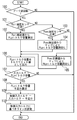
図3はプーリ圧制御部64におけるプーリ逆回転にかかる制御の流れを示すフローチャートである。
まずステップ100では、プーリの逆回転が発生しているかどうかをチェックする。このプーリの逆回転は、例えば第1プライマリプーリ速度センサ26と第2プライマリプーリ速度センサ28とを90度位相を異ならせて配置し、それぞれのセンサでピックアップされる波形の位相差から回転方向を判断するとともに、この回転方向とインヒビタスイッチ23のレンジ信号とを比較することで、プーリの逆回転かどうかをチェックすることができる。プーリの逆回転が発生しているときは、ステップ110に進み、発生していなければこのフローを終了する。
ステップ101において、プライマリ圧(Ppri)油圧センサ32が正常であるかどうかをチェックする。プライマリ圧油圧センサ32が正常であればステップ102に進み、プライマリ圧油圧センサ32の検出値であるプライマリ圧Ppriを用いてPLpriトルク容量を算出する。
【0022】
ステップ101のチェックでプライマリ圧油圧センサ32が故障であった場合は、ステップ103へ進み、セカンダリ圧(Psec)油圧センサ33が正常であるかどうかをチェックする。セカンダリ圧油圧センサ33が正常であればステップ104へ進み、故障の場合はステップ105へ進む。
ステップ104では、図4に示すようなセカンダリ圧−PLpriトルク容量マップを用いて、セカンダリ圧油圧センサ33の検出値であるセカンダリ圧PsecからPLpriトルク容量を推定値として求める。
【0023】
このマップは、プーリの逆回転が発生しているときにはプライマリ圧がセカンダリ圧の略60%程度に低下することを踏まえて、セカンダリ圧に対応してプライマリ圧を推定し、この推定した各プライマリ圧に基づいてあらかじめプライマリプーリのトルク容量を算出しておき、セカンダリ圧から直接PLpriトルク容量を読み出すことができるようにしたものである。
【0024】
一方、ステップ105では、セカンダリ圧油圧センサ33からの出力を用いず、セカンダリ圧目標値をセカンダリ圧として、上記のセカンダリ圧−PLpriトルク容量マップからPLpriトルク容量を読み出す。
【0025】
以上のようにして、ステップ102あるいはステップ104、105でPpriトルク容量を求めた後、ステップ106において、PLpriトルク容量をトルクリミット値としてエンジンコントロールユニット22へ送出する。エンジンコントロールユニット22はこのトルクリミット値を上限としてエンジンの出力(エンジン実トルク)を制御するので、エンジン実トルクがこのトルクリミット値よりも大きいときにはトルクダウンが行なわれることとなる。なお、このトルクリミット値は算出されたPLpriトルク容量以下であればよいが、トルクリミット値の上限を小さな値に設定するほど動力性能が低下するので、上限をPLpriトルク容量に設定することが好ましい。
【0026】
つぎに、ステップ107においては、入力トルクとPLpriトルク容量を比較する。ここで入力トルクとしては、アクセルストロークセンサ16からのアクセルストローク量とエンジン回転速度とから算出されるエンジンが要求されているトルクであるエンジン要求トルクを用いており、CVTコントロールユニット20から送出されたトルクリミット値を反映していない値である。入力トルクがPLpriトルク容量より大きいときはステップ108へ進み、入力トルクがPLpriトルク容量以下のときは終了する。
【0027】
ステップ108では、入力トルクに対するPLpriトルク容量の不足分(入力トルク−PLpriトルク容量)を算出する。そして、ステップ109において、入力トルクに上記PLpriトルク容量の不足分を補正量として加算し、制御入力トルクとする。なお、補正量には必要に応じてゲインやオフセットを設けることができる。
このあと、ステップ110で、上記制御入力トルクに基づいてライン圧を設定する。
【0028】
本実施例においては、ステップ100が発明におけるプーリの逆回転検知手段を構成し、ステップ101から105がプライマリプーリトルク容量算出手段を、そしてステップ16から110がプーリ逆回転時制御手段を構成している。
【0029】
本実施例は以上のように構成され、プーリの逆回転時に、プライマリ圧油圧センサによるプライマリ圧から算出したプライマリプーリのトルク容量に基づいてライン圧増大補正などの制御を行なうベルトCVTにおいて、プライマリ圧油圧センサの故障時にはセカンダリ圧油圧センサで検出したセカンダリ圧に基づいてPLpriトルク容量を算出するものとしたので、制御不能となることなく、適正な制御が確保される。
【0030】
また、セカンダリ圧油圧センサも故障しているときには、セカンダリ圧としてセカンダリ圧目標値を用いてプライマリプーリのトルク容量を算出するので、プライマリ圧、セカンダリ圧の両油圧センサの故障にもかかわらず、プライマリプーリのトルク容量に基づく制御を継続することができる。
【0031】
そして、セカンダリ圧に基づくプライマリプーリのトルク容量の算出は、セカンダリ圧に対応してプライマリ圧を推定し、推定した各プライマリ圧に基づいてあらかじめプライマリプーリのトルク容量を算出したマップを用いて、セカンダリ圧(Psec)からプライマリプーリトルク容量(PLpriトルク容量)を読み出すものとしているので、複雑な演算処理等が不要で、処理が簡単である。
【0032】
さらに、プライマリプーリおよびセカンダリプーリにはそれぞれライン圧を元圧とするプライマリ圧およびセカンダリ圧を作用させており、プライマリ圧からプライマリプーリトルク容量を算出するとともに、プーリの逆回転を検知し、プーリの逆回転時には入力トルクとセカンダリ圧から推定されたプライマリプーリトルク容量とを比較し、入力トルクの方が大きいときは、プライマリプーリトルク容量の不足分に対応して入力トルクを増大補正してこれに基づいてライン圧を設定するものとしたので、プーリの逆回転時にバランスが崩れたプライマリ圧を上昇させることができ、プライマリ圧油圧センサが故障してもプライマリプーリとVベルトの滑りが防止される。
ライン圧増大をプーリの逆回転時を検出したときに行なっているので、不必要に高油圧となり動力性能を低下させるようなこともない。
【0033】
とくに、入力トルクの増大補正として、入力トルクにセカンダリ圧から推定されたプライマリプーリトルク容量の不足分を加算するようにしたので、プライマリ圧油圧センサが故障してもプライマリプーリのトルク容量を適正なものとすることができる。
【0034】
さらに、エンジンコントロールユニット22では油圧に比べて応答性のよいトルクダウン制御をあわせて行なうことで、プーリの逆回転を検出したら早期にセカンダリ圧から推定されたプライマリプーリのトルク容量以下のエンジントルクに制御することができ、プライマリ圧油圧センサが故障しても確実にVベルトの滑りの発生を防止することができる。さらに、上記したように随時算出されるプライマリプーリのトルク容量を上限にエンジンの出力を制御するので、その後のVベルトの滑りを防止できるとともに、徐々にエンジン要求トルクよりもエンジンのトルクリミット値の方が大きくなって、実際にはエンジンのトルクダウンは行なわれないこととなるため、さらに動力性能の悪化を防止できる。
なお、プーリの逆回転の検知処理について、上記実施の形態ではその一例をステップ100で説明したが、これに限定されることはなく、他の適宜の検知処理によって行なうことができるのはもちろんである。
【0035】
【発明の効果】
以上のとおり、本発明は、プライマリ圧からプライマリプーリのトルク容量を算出するプライマリプーリトルク容量算出手段を有し、プーリの逆回転時にプライマリプーリのトルク容量に基づいて例えばライン圧増大補正など所定の制御を行なうベルト式無段変速機において、プライマリ圧油圧センサの故障時には、セカンダリ圧油圧センサで検出したセカンダリ圧に基づいてプライマリプーリのトルク容量を算出するものとしたので、制御不能となることなく、適正な制御が確保される。
【図面の簡単な説明】
【図1】本発明を適用したVベルト式無段変速機の概略構成を示す図である。
【図2】油圧コントロールユニットおよびCVTコントロールユニットの概略構成を示す図である。
【図3】プーリ逆回転にかかる制御の流れを示すフローチャートである。
【図4】セカンダリ圧−プライマリプーリトルク容量マップを示す図である。
【符号の説明】
1 エンジン
2 ベルトCVT(ベルト式無段変速機)
3 トルクコンバータ
4 前後進切り替え機構
5 変速機構部
6 ディファレンシャル
10 プライマリプーリ
10a 可動円錐板
10b 固定円錐板
10c プライマリプーリシリンダ室
11 セカンダリプーリ
11a 可動円錐板
11b 固定円錐板
11c セカンダリプーリシリンダ室
12 Vベルト
13 出力軸
14 アイドラギア
15 エンジン回転数センサ
16 アクセルストロークセンサ
20 CVTコントロールユニット
22 エンジンコントロールユニット
23 インヒビタースイッチ
24 スロットル開度センサ
25 温度センサ
26 第1プライマリプーリ速度センサ
27 セカンダリプーリ速度センサ
28 第2プライマリプーリ速度センサ
29 ライン圧センサ
30 変速制御弁
32 プライマリ圧油圧センサ
33 セカンダリ圧油圧センサ
34 ソレノイド
35 調圧弁
36 ソレノイド
37 減圧弁
38 油圧ポンプ
60 油圧コントロールユニット
62 変速制御部
64 プーリ圧制御部[0001]
BACKGROUND OF THE INVENTION
The present invention relates to a hydraulic sensor fail control device for a belt type continuously variable transmission.
[0002]
[Prior art]
[Patent Document 1]
Conventionally, as a continuously variable transmission suitable for vehicles, for example, a belt type continuously variable transmission (hereinafter referred to as a belt CVT) using a V-belt as disclosed in Japanese Patent Laid-Open No. 8-210449. There is.
This is because a V-belt is stretched between a primary pulley connected to the engine side and a secondary pulley connected to the axle side to form a transmission mechanism, and the groove width of the primary pulley and the secondary pulley can be changed by hydraulic pressure. It is something to control.
Then, the thrust of the pulley is obtained according to the input torque and the gear ratio, this thrust is converted into a hydraulic pressure based on a predetermined value such as the pressure receiving area of the secondary pulley and the primary pulley, and this hydraulic pressure is supplied to the transmission mechanism as a target line pressure. To do.
[0003]
The primary pulley and the secondary pulley are respectively provided with first and second cylinder chambers. The primary pressure obtained by regulating the line pressure is regulated to the first cylinder chamber, and the line pressure or line pressure is regulated to the second cylinder chamber. Each secondary pressure is supplied. During traveling, the groove widths of the primary pulley and the secondary pulley are changed by the hydraulic pressure supplied to each cylinder chamber, and the gear ratio is continuously set corresponding to the contact radius ratio (pulley ratio) between the V belt and each pulley. Change.
[0004]
[Problems to be solved by the invention]
By the way, with such a belt CVT, when traveling uphill in the forward D range, the foot is released from the accelerator pedal, the brake is applied, and the vehicle is temporarily stopped in the D range. When the vehicle moves slightly backward due to separation, reverse torque is applied to the output shaft of the belt CVT, and reverse rotation occurs in the pulley.
When the pulley rotates in reverse, even if the pulley ratio, input torque, input speed, and secondary pressure are the same, the hydraulic balance between the primary pressure and the secondary pressure is lost, especially the primary pressure is halved and the torque capacity of the primary pulley is reduced. There is a risk of belt slippage. However, since control for coping with this loss of hydraulic balance has not been performed in the past, there has been no consideration of the case where the primary pressure hydraulic sensor has failed.
[0005]
The reverse rotation of the pulley as described above also occurs when the vehicle is retreated in the R range on the downhill, and then temporarily stops and then restarts in the R range. Similarly, the torque capacity of the primary pulley decreases.
That is, the reverse rotation of the pulley in question here is the normal rotation direction of the pulley assumed at the currently selected range position (forward direction if the D range, reverse direction if the R range). This refers to the phenomenon of reverse rotation of the pulley. Hereinafter, “reverse rotation of the pulley” is used in this sense.
[0006]
Therefore, in view of the above-described conventional problems, the present invention is a belt-type continuously variable motor capable of accurately calculating the torque capacity of the primary pulley even when the primary pressure hydraulic sensor fails during reverse rotation of the pulley. An object of the present invention is to provide a hydraulic pressure sensor fail control device for a transmission.
[0007]
[Means for Solving the Problems]
For this reason, the present invention forms a transmission mechanism section by laying a belt between a primary pulley and a secondary pulley, detects a primary pressure, a secondary pressure oil pressure sensor that detects a secondary pressure, and a reverse of the pulley. Pulley reverse rotation detecting means for detecting rotation, primary pulley torque capacity calculating means for calculating the torque capacity of the primary pulley from the primary pressure detected by the primary pressure oil pressure sensor, and the reverse of the pulley detected by the reverse rotation detecting means. In a belt-type continuously variable transmission that includes a pulley reverse rotation control means that performs predetermined control based on the torque capacity of the primary pulley calculated by the primary pulley torque capacity calculation means during rotation, the primary pulley torque capacity calculation means includes If the primary pressure sensor fails, It was assumed to calculate the torque capacity of the primary pulley on the basis of the detected secondary pressure in Secondary hydraulic pressure sensor.
[0008]
DETAILED DESCRIPTION OF THE INVENTION
Next, an embodiment of the present invention will be described.
FIG. 1 shows a schematic configuration of a belt CVT to which the present invention is applied, and FIG. 2 shows a schematic configuration of a hydraulic control unit and a CVT control unit.
A
[0009]
The transmission ratio of the
[0010]
The
The
[0011]
The
The
[0012]
The input torque input from the engine 1 is input to the
[0013]
The
Since the
In addition, the oil temperature of the
[0014]
As shown in FIG. 2, the
The speed
[0015]
The line pressure control system is composed of a
[0016]
The gear ratio between the
The
[0017]
The
[0018]
The pulley
[0019]
The pulley
[0020]
Here, the PLpri torque capacity is calculated from the primary pressure Ppri by the primary pressure
Further, when the secondary pressure oil pressure sensor also fails, the PLpri torque capacity estimation value is obtained from the above map using the secondary pressure target value originally calculated by the pulley
[0021]
FIG. 3 is a flowchart showing a control flow relating to pulley reverse rotation in the pulley
First, in
In
[0022]
If it is determined in
In
[0023]
This map estimates the primary pressure corresponding to the secondary pressure based on the fact that the primary pressure drops to about 60% of the secondary pressure when reverse rotation of the pulley occurs, and the estimated primary pressure The torque capacity of the primary pulley is calculated in advance based on the above, and the PLpri torque capacity can be read directly from the secondary pressure.
[0024]
On the other hand, in
[0025]
After obtaining the Ppri torque capacity in
[0026]
Next, in
[0027]
In
Thereafter, in
[0028]
In this embodiment,
[0029]
In the belt CVT configured as described above and performing control such as line pressure increase correction based on the torque capacity of the primary pulley calculated from the primary pressure by the primary pressure oil pressure sensor during reverse rotation of the pulley, the primary pressure Since the PLpri torque capacity is calculated based on the secondary pressure detected by the secondary pressure oil pressure sensor when the hydraulic pressure sensor fails, proper control is ensured without being disabled.
[0030]
When the secondary pressure oil pressure sensor is also broken, the primary pulley torque capacity is calculated using the secondary pressure target value as the secondary pressure. Control based on the torque capacity of the pulley can be continued.
[0031]
Then, the calculation of the torque capacity of the primary pulley based on the secondary pressure is performed by estimating the primary pressure corresponding to the secondary pressure and using the map in which the torque capacity of the primary pulley is calculated in advance based on each estimated primary pressure. Since the primary pulley torque capacity (PLpri torque capacity) is read from the pressure (Psec), complicated calculation processing or the like is unnecessary, and the processing is simple.
[0032]
Furthermore, the primary pressure and the secondary pressure are applied to the primary pulley and the secondary pulley, respectively, and the primary pulley torque capacity is calculated from the primary pressure and the reverse rotation of the pulley is detected to detect the pulley rotation. During reverse rotation, the input torque is compared with the primary pulley torque capacity estimated from the secondary pressure.If the input torque is larger, the input torque is corrected to increase corresponding to the shortage of the primary pulley torque capacity. Since the line pressure is set on the basis of this, the primary pressure that is out of balance can be raised during the reverse rotation of the pulley, and even if the primary pressure hydraulic pressure sensor fails, the primary pulley and the V belt are prevented from slipping. .
Since the line pressure is increased when the reverse rotation of the pulley is detected, the hydraulic pressure becomes unnecessarily high and the power performance is not deteriorated.
[0033]
In particular, as an increase correction of the input torque, the shortage of the primary pulley torque capacity estimated from the secondary pressure is added to the input torque. Can be.
[0034]
Furthermore, the
An example of the reverse rotation detection process of the pulley has been described in
[0035]
【The invention's effect】
As described above, the present invention has primary pulley torque capacity calculating means for calculating the torque capacity of the primary pulley from the primary pressure, and is based on the torque capacity of the primary pulley during reverse rotation of the pulley. In a belt type continuously variable transmission that performs control, when the primary pressure / hydraulic sensor fails, the torque capacity of the primary pulley is calculated based on the secondary pressure detected by the secondary pressure / hydraulic sensor. Appropriate control is ensured.
[Brief description of the drawings]
FIG. 1 is a diagram showing a schematic configuration of a V-belt type continuously variable transmission to which the present invention is applied.
FIG. 2 is a diagram showing a schematic configuration of a hydraulic control unit and a CVT control unit.
FIG. 3 is a flowchart showing a flow of control for pulley reverse rotation.
FIG. 4 is a diagram showing a secondary pressure-primary pulley torque capacity map.
[Explanation of symbols]
1
3
Claims (5)
プライマリ圧を検出するプライマリ圧油圧センサと、
セカンダリ圧を検出するセカンダリ圧油圧センサと、
プーリの逆回転を検知するプーリの逆回転検知手段と、
前記プライマリ圧油圧センサによって検出されたプライマリ圧からプライマリプーリのトルク容量を算出するプライマリプーリトルク容量算出手段と、
前記逆回転検知手段によって検出されたプーリの逆回転時に前記プライマリプーリトルク容量算出手段によって算出されたプライマリプーリのトルク容量に基づいて所定の制御を行なうプーリ逆回転時制御手段とを備えるベルト式無段変速機において、
前記プライマリプーリトルク容量算出手段は、前記プライマリ圧油圧センサの故障時には前記セカンダリ圧油圧センサで検出したセカンダリ圧に基づいてプライマリプーリのトルク容量を算出することを特徴とするベルト式無段変速機の油圧センサフェール制御装置。A transmission mechanism is formed by spanning a belt between pulleys composed of a primary pulley connected to the engine side and a secondary pulley connected to the output shaft. Acting on the pulley and the secondary pulley,
A primary pressure hydraulic sensor for detecting the primary pressure;
A secondary pressure oil pressure sensor for detecting the secondary pressure;
A pulley reverse rotation detecting means for detecting the reverse rotation of the pulley;
Primary pulley torque capacity calculating means for calculating the torque capacity of the primary pulley from the primary pressure detected by the primary pressure oil pressure sensor ;
A pulley type non-revolving control means for performing a predetermined control based on the torque capacity of the primary pulley calculated by the primary pulley torque capacity calculating means during the reverse rotation of the pulley detected by the reverse rotation detecting means. In a step transmission,
The primary pulley torque capacity calculation means calculates the torque capacity of the primary pulley based on the secondary pressure detected by the secondary pressure oil pressure sensor when the primary pressure oil pressure sensor fails. Hydraulic sensor fail control device.
前記セカンダリ圧油圧センサも故障時にはセカンダリ圧としてセカンダリ圧目標値を用いてプライマリプーリのトルク容量を算出することを特徴とする請求項1記載のベルト式無段変速機の油圧センサフェール制御装置。The primary pulley torque capacity calculating means includes
2. The hydraulic sensor fail control device for a belt type continuously variable transmission according to claim 1, wherein when the secondary pressure / hydraulic sensor also fails, the torque capacity of the primary pulley is calculated using the secondary pressure target value as the secondary pressure.
セカンダリ圧に対応してプライマリ圧を推定し、推定した各プライマリ圧に基づいてあらかじめプライマリプーリのトルク容量を算出したマップを備え、
セカンダリ圧からプライマリプーリのトルク容量を読み出すことを特徴とする請求項1または2記載のベルト式無段変速機の油圧センサフェール制御装置。The primary pulley torque capacity calculating means includes
A primary pressure is estimated corresponding to the secondary pressure, and a torque capacity of the primary pulley is calculated in advance based on each estimated primary pressure.
3. The hydraulic sensor fail control device for a belt type continuously variable transmission according to claim 1, wherein the torque capacity of the primary pulley is read from the secondary pressure.
Priority Applications (5)
| Application Number | Priority Date | Filing Date | Title |
|---|---|---|---|
| JP2002257547A JP4038097B2 (en) | 2002-09-03 | 2002-09-03 | Hydraulic sensor fail control device for belt type continuously variable transmission |
| DE60310838T DE60310838T2 (en) | 2002-09-03 | 2003-08-15 | Stepless transmission control system in the event of failure of a hydraulic pressure sensor |
| EP03255082A EP1403568B1 (en) | 2002-09-03 | 2003-08-15 | Hydraulic pressure sensor failure control system for belt-type continuously variable transmission |
| US10/647,900 US7192372B2 (en) | 2002-09-03 | 2003-08-25 | Hydraulic pressure sensor failure control system for belt-type continuously variable transmission |
| KR10-2003-0059390A KR100510801B1 (en) | 2002-09-03 | 2003-08-27 | Oil Pressure Sensor Fail Control Device For Continuously Variable Transmission |
Applications Claiming Priority (1)
| Application Number | Priority Date | Filing Date | Title |
|---|---|---|---|
| JP2002257547A JP4038097B2 (en) | 2002-09-03 | 2002-09-03 | Hydraulic sensor fail control device for belt type continuously variable transmission |
Publications (2)
| Publication Number | Publication Date |
|---|---|
| JP2004092846A JP2004092846A (en) | 2004-03-25 |
| JP4038097B2 true JP4038097B2 (en) | 2008-01-23 |
Family
ID=31972996
Family Applications (1)
| Application Number | Title | Priority Date | Filing Date |
|---|---|---|---|
| JP2002257547A Expired - Fee Related JP4038097B2 (en) | 2002-09-03 | 2002-09-03 | Hydraulic sensor fail control device for belt type continuously variable transmission |
Country Status (5)
| Country | Link |
|---|---|
| US (1) | US7192372B2 (en) |
| EP (1) | EP1403568B1 (en) |
| JP (1) | JP4038097B2 (en) |
| KR (1) | KR100510801B1 (en) |
| DE (1) | DE60310838T2 (en) |
Families Citing this family (13)
| Publication number | Priority date | Publication date | Assignee | Title |
|---|---|---|---|---|
| JP4107484B2 (en) * | 2002-09-27 | 2008-06-25 | ジヤトコ株式会社 | Shift control device for V-belt continuously variable automatic transmission |
| JP4687096B2 (en) * | 2004-02-10 | 2011-05-25 | トヨタ自動車株式会社 | Control device for belt type continuously variable transmission |
| JP4317084B2 (en) * | 2004-06-10 | 2009-08-19 | ジヤトコ株式会社 | Hydraulic control device and control method thereof |
| KR100588511B1 (en) * | 2004-11-24 | 2006-06-09 | 현대자동차주식회사 | Primary pulley control system of continuously variable transmission and method thereof |
| KR20060068099A (en) * | 2004-12-15 | 2006-06-21 | 현대자동차주식회사 | Control method for promotion of safety ratio of continuously variable transmission |
| JP2008020055A (en) * | 2006-06-15 | 2008-01-31 | Toyota Motor Corp | Control device of belt type continuously variable transmission |
| JP5051007B2 (en) * | 2008-06-03 | 2012-10-17 | 日産自動車株式会社 | Control device for releasing idle stop of vehicle drive system |
| US8731792B2 (en) * | 2011-09-23 | 2014-05-20 | GM Global Technology Operations LLC | System and method for estimating hydraulic pressure within and controlling a dry dual clutch transmission |
| JP2013072479A (en) * | 2011-09-27 | 2013-04-22 | Toyota Motor Corp | Control device of vehicle continuously variable transmission |
| JP6866585B2 (en) * | 2016-08-01 | 2021-04-28 | 日本電産トーソク株式会社 | Hydraulic control device and program |
| CN109964059B (en) * | 2016-11-24 | 2022-12-02 | 日产自动车株式会社 | Continuously variable transmission |
| CN111051745B (en) * | 2017-08-23 | 2021-06-11 | 日产自动车株式会社 | Control method and control device for continuously variable transmission |
| JP6973186B2 (en) * | 2018-03-05 | 2021-11-24 | トヨタ自動車株式会社 | Vehicle control device |
Family Cites Families (8)
| Publication number | Priority date | Publication date | Assignee | Title |
|---|---|---|---|---|
| US5092198A (en) * | 1989-12-19 | 1992-03-03 | Mazda Motor Corporation | Control apparatus for stepless transmission |
| JP2626257B2 (en) * | 1990-12-28 | 1997-07-02 | トヨタ自動車株式会社 | Hydraulic control device for belt-type continuously variable transmission for vehicles |
| JP3654072B2 (en) * | 1999-08-25 | 2005-06-02 | 三菱自動車工業株式会社 | Hydraulic circuit of belt type continuously variable transmission |
| DE19952476A1 (en) * | 1999-10-29 | 2001-05-23 | Zahnradfabrik Friedrichshafen | Method for controlling a CVT automatic gearbox records detected main pressure and detected application pressure from a secondary disk as signals on an electronic gearbox control |
| KR100399248B1 (en) * | 1999-11-22 | 2003-09-26 | 미쯔비시 지도샤 고교 가부시끼가이샤 | Control appratus of endless transmission for vehicles |
| JP3698957B2 (en) * | 2000-06-02 | 2005-09-21 | 三菱電機株式会社 | Hydraulic control device for continuously variable transmission |
| JP4126152B2 (en) * | 2000-09-26 | 2008-07-30 | ジヤトコ株式会社 | Shift control device for continuously variable transmission |
| JP3993489B2 (en) * | 2002-08-26 | 2007-10-17 | ジヤトコ株式会社 | Belt slip prevention device for belt type continuously variable transmission |
-
2002
- 2002-09-03 JP JP2002257547A patent/JP4038097B2/en not_active Expired - Fee Related
-
2003
- 2003-08-15 EP EP03255082A patent/EP1403568B1/en not_active Expired - Fee Related
- 2003-08-15 DE DE60310838T patent/DE60310838T2/en not_active Expired - Lifetime
- 2003-08-25 US US10/647,900 patent/US7192372B2/en not_active Expired - Fee Related
- 2003-08-27 KR KR10-2003-0059390A patent/KR100510801B1/en not_active IP Right Cessation
Also Published As
| Publication number | Publication date |
|---|---|
| EP1403568B1 (en) | 2007-01-03 |
| DE60310838D1 (en) | 2007-02-15 |
| DE60310838T2 (en) | 2007-10-25 |
| US20040092343A1 (en) | 2004-05-13 |
| KR100510801B1 (en) | 2005-08-30 |
| US7192372B2 (en) | 2007-03-20 |
| EP1403568A1 (en) | 2004-03-31 |
| KR20040020791A (en) | 2004-03-09 |
| JP2004092846A (en) | 2004-03-25 |
Similar Documents
| Publication | Publication Date | Title |
|---|---|---|
| JP3696474B2 (en) | Hydraulic control device for continuously variable transmission | |
| JP3993489B2 (en) | Belt slip prevention device for belt type continuously variable transmission | |
| EP1818575B1 (en) | Control device for a continuously variable transmission and control method thereof | |
| US8326503B2 (en) | Lock-up clutch control device | |
| US8298121B2 (en) | Lock-up clutch control apparatus | |
| US20090298625A1 (en) | Control device and control method for continuously variable transmission | |
| JP4038097B2 (en) | Hydraulic sensor fail control device for belt type continuously variable transmission | |
| EP1393960A2 (en) | Engine torque control apparatus | |
| JP3732817B2 (en) | Control device for automatic transmission | |
| US6960153B2 (en) | Clutch engagement control of automatic transmission | |
| JP2004124965A (en) | Controller for belt type continuously variable transmission | |
| EP3273109A1 (en) | Transmission control device and transmission control method | |
| JP4553549B2 (en) | Control device for belt type continuously variable transmission | |
| JP3944042B2 (en) | Hydraulic pressure reduction rate limiting device for V-belt type continuously variable transmission | |
| US6135916A (en) | Process for controlling the pressure of a CVT during a standing start | |
| US10704680B2 (en) | Transmission control device and transmission control method | |
| JP4101563B2 (en) | Slip prevention device for continuously variable transmission for vehicle | |
| JP2001263473A (en) | Hydraulic control device for continuously variable transmission | |
| JP4198423B2 (en) | Belt slip prevention device for V-belt type continuously variable transmission | |
| JP2004092847A (en) | Hydraulic control device of vehicular automatic transmission | |
| JP2004124968A (en) | Controller for belt type continuously variable transmission | |
| JP2004263737A (en) | Shift control device for continuously variable transmission | |
| JP2008039154A (en) | Hydraulic control device for belt type continuously variable transmission | |
| JP2009138871A (en) | Control device of stepless transmission | |
| JP2004125015A (en) | Hydraulic pressure control device for belt type continuously variable transmission |
Legal Events
| Date | Code | Title | Description |
|---|---|---|---|
| A621 | Written request for application examination |
Free format text: JAPANESE INTERMEDIATE CODE: A621 Effective date: 20040819 |
|
| A977 | Report on retrieval |
Free format text: JAPANESE INTERMEDIATE CODE: A971007 Effective date: 20061221 |
|
| A131 | Notification of reasons for refusal |
Free format text: JAPANESE INTERMEDIATE CODE: A131 Effective date: 20070116 |
|
| A521 | Written amendment |
Free format text: JAPANESE INTERMEDIATE CODE: A523 Effective date: 20070315 |
|
| TRDD | Decision of grant or rejection written | ||
| A01 | Written decision to grant a patent or to grant a registration (utility model) |
Free format text: JAPANESE INTERMEDIATE CODE: A01 Effective date: 20071030 |
|
| A61 | First payment of annual fees (during grant procedure) |
Free format text: JAPANESE INTERMEDIATE CODE: A61 Effective date: 20071102 |
|
| R150 | Certificate of patent or registration of utility model |
Free format text: JAPANESE INTERMEDIATE CODE: R150 |
|
| FPAY | Renewal fee payment (event date is renewal date of database) |
Free format text: PAYMENT UNTIL: 20101109 Year of fee payment: 3 |
|
| FPAY | Renewal fee payment (event date is renewal date of database) |
Free format text: PAYMENT UNTIL: 20101109 Year of fee payment: 3 |
|
| FPAY | Renewal fee payment (event date is renewal date of database) |
Free format text: PAYMENT UNTIL: 20111109 Year of fee payment: 4 |
|
| FPAY | Renewal fee payment (event date is renewal date of database) |
Free format text: PAYMENT UNTIL: 20111109 Year of fee payment: 4 |
|
| FPAY | Renewal fee payment (event date is renewal date of database) |
Free format text: PAYMENT UNTIL: 20121109 Year of fee payment: 5 |
|
| FPAY | Renewal fee payment (event date is renewal date of database) |
Free format text: PAYMENT UNTIL: 20121109 Year of fee payment: 5 |
|
| FPAY | Renewal fee payment (event date is renewal date of database) |
Free format text: PAYMENT UNTIL: 20131109 Year of fee payment: 6 |
|
| FPAY | Renewal fee payment (event date is renewal date of database) |
Free format text: PAYMENT UNTIL: 20131109 Year of fee payment: 6 |
|
| FPAY | Renewal fee payment (event date is renewal date of database) |
Free format text: PAYMENT UNTIL: 20141109 Year of fee payment: 7 |
|
| LAPS | Cancellation because of no payment of annual fees |