JP4037632B2 - Control device for internal combustion engine provided with fuel injection device - Google Patents
Control device for internal combustion engine provided with fuel injection device Download PDFInfo
- Publication number
- JP4037632B2 JP4037632B2 JP2001302694A JP2001302694A JP4037632B2 JP 4037632 B2 JP4037632 B2 JP 4037632B2 JP 2001302694 A JP2001302694 A JP 2001302694A JP 2001302694 A JP2001302694 A JP 2001302694A JP 4037632 B2 JP4037632 B2 JP 4037632B2
- Authority
- JP
- Japan
- Prior art keywords
- current
- solenoid
- combustion engine
- internal combustion
- switch circuit
- Prior art date
- Legal status (The legal status is an assumption and is not a legal conclusion. Google has not performed a legal analysis and makes no representation as to the accuracy of the status listed.)
- Expired - Lifetime
Links
Images


Classifications
-
- F—MECHANICAL ENGINEERING; LIGHTING; HEATING; WEAPONS; BLASTING
- F02—COMBUSTION ENGINES; HOT-GAS OR COMBUSTION-PRODUCT ENGINE PLANTS
- F02D—CONTROLLING COMBUSTION ENGINES
- F02D41/00—Electrical control of supply of combustible mixture or its constituents
- F02D41/20—Output circuits, e.g. for controlling currents in command coils
- F02D2041/2017—Output circuits, e.g. for controlling currents in command coils using means for creating a boost current or using reference switching
-
- F—MECHANICAL ENGINEERING; LIGHTING; HEATING; WEAPONS; BLASTING
- F02—COMBUSTION ENGINES; HOT-GAS OR COMBUSTION-PRODUCT ENGINE PLANTS
- F02D—CONTROLLING COMBUSTION ENGINES
- F02D41/00—Electrical control of supply of combustible mixture or its constituents
- F02D41/20—Output circuits, e.g. for controlling currents in command coils
- F02D2041/202—Output circuits, e.g. for controlling currents in command coils characterised by the control of the circuit
- F02D2041/2034—Control of the current gradient
-
- F—MECHANICAL ENGINEERING; LIGHTING; HEATING; WEAPONS; BLASTING
- F02—COMBUSTION ENGINES; HOT-GAS OR COMBUSTION-PRODUCT ENGINE PLANTS
- F02D—CONTROLLING COMBUSTION ENGINES
- F02D41/00—Electrical control of supply of combustible mixture or its constituents
- F02D41/20—Output circuits, e.g. for controlling currents in command coils
- F02D2041/202—Output circuits, e.g. for controlling currents in command coils characterised by the control of the circuit
- F02D2041/2055—Output circuits, e.g. for controlling currents in command coils characterised by the control of the circuit with means for determining actual opening or closing time
Description
【0001】
【発明の属する技術分野】
本発明は、内燃機関の制御装置に係り、特に、ソレノイドを有する燃料噴射装置を備えた内燃機関のソレノイドに印可する電流波形を制御する制御装置に関する。
【0002】
【従来の技術】
従来、内燃機関の燃焼室に燃料を噴射する燃料噴射弁(インジェクタ)は、燃料噴射弁内に、プランジャーと、該プランジャーを開弁方向に付勢するソレノイドと、前記プランジャーを閉弁方向に付勢するスプリングとを備えていると共に、燃料噴射弁に供給される燃料圧力は高圧状態にあって、該高圧の燃料圧力でプランジャーを閉弁方向に付勢する状態になっている。
【0003】
また、前記ソレノイド(インジェクタ)に印加される電流は、バッテリを電源とするものであって、その印可駆動電流は、単一の電流波形であり、内燃機関の燃焼室への燃料噴射弁からの燃料の噴射制御は、制御装置からの燃料噴射弁のソレノイドへの印可信号に基づいて前記単一の電流波形の電流が印加されることによって行われている。
【0004】
例えば、特開平11−13519号公報や特開平11−343910号公報に所載の燃料噴射弁の燃料噴射のためのソレノイド印加制御は、燃料噴射弁(インジェクタ)の駆動電流波形が、一段の開弁信号と一段の保持信号からなる2段階の単一の駆動電流波形をしているものであり、内燃機関の運転状態に基づいて燃料噴射パルス幅を変化させて、内燃機関の燃焼室に噴射供給する燃料の噴射量を制御して内燃機関の燃焼を制御するものである。
【0005】
【発明が解決しようとする課題】
ところで、近年、内燃機関に装置される燃料噴射弁(インジェクタ)は、種々の要求からその小型化が強く求められるようになって来ている。しかし、燃料噴射弁(インジェクタ)が小型化されると、該燃料噴射弁(インジェクタ)に内蔵されているソレノイドのインダクタンス値が小さいものとなってしまい、該ソレノイドに印加される前記したような従来の単一の電流波形では、起磁力が小さくなることがあって、この場合は、ソレノイドによる燃料噴射弁(インジェクタ)に内蔵されているプランジャーの吸引力が小さいものでなってしまう。特に、供給される燃料が高圧の状態にある場合には、時としてソレノイドの起磁力ではプランジャーを吸引することができず、燃料噴射弁からの燃料噴射ができなくなる可能性がある。
【0006】
また、燃料噴射弁(インジェクタ)は、その一噴射において燃料をどの程度最小量として噴射できるか、つまり燃料噴射弁の一燃料噴射における最小燃料噴射量特性も重要なことである。該最小燃料噴射量特性は、特に成層リーン燃焼時に求められるものであり、該最小燃料噴射量特性は、燃費、エミッション特性に重要なことである。
【0007】
本発明は、前記点に鑑みてなされたものであって、その目的とするところは、燃料噴射弁(インジェクタ)の小型化によりソレノイドのインダクタンス値が小さくなっても、最適に燃料噴射でき、且つ、最小燃料噴射量特性の優れた燃料噴射装置を備えた内燃機関の制御装置を提供することにある。
【0008】
【課題を解決するための手段】
前記目的を達成すべく、本発明の内燃機関の制御装置は、基本的には、ソレノイドを有する燃料噴射装置を備えた内燃機関の制御装置であって、該制御装置は、内燃機関の運転状態を検出する手段と、該運転状態に基づき燃料噴射パルス幅を算出する手段と、前記ソレノイドを制御するソレノイド制御手段と、を備え、該ソレノイド制御手段は、前記燃料噴射パルス幅に基づき前記ソレノイドに電流を供給して制御するものであって、最初、大きな所定電流値に至るまで前記ソレノイドに開弁電流を供給し、該開弁電流が所定電流値に至った後は、前記ソレノイドを開弁状態に保持するべく、前記内燃機関の運転状態の燃料噴射量有効最小パルス幅特性( Qmin 特性)が重要な領域か否かを判断して複数の異なる電流波形の小さな電流値の保持電流の内の一つを切換え供給して前記ソレノイドを制御することを特徴としている。
【0009】
また、本発明の内燃機関の制御装置の具体的な態様は、ソレノイド制御手段は、バッテリからの電力を昇圧する昇圧回路と、前記昇圧回路から電力を前記ソレノイドに供給する第一スイッチ回路と、前記バッテリから電力を前記ソレノイドに供給する第二スイッチ回路と、前記ソレノイドからグランド方向に電流をシンクする第三スイッチ回路と、前記第一スイッチ回路と前記第二スイッチ回路とがオフのとき、グランドから前記ソレノイドと前記第三スイッチ回路を介してグランドに電流を回帰させるフライホイール回路と、を備えていることを特徴としている。
【0010】
更に、本発明の内燃機関の制御装置の他の具体的な態様は、前記ソレノイドに供給する前記複数の電流波形は、一段開弁二段保持の第一電流波形、一段開弁一段保持の第二電流波形、及び、前記第二電流波形とは異なる一段開弁一段保持の第三電流波形、の三種類の電流波形であることを特徴としている。
【0011】
前記の如く構成された本発明の内燃機関の制御装置は、インジェクタの小型化による該インジェクタのソレノイドのインダクタンスが小さい場合における高燃圧時でも、インジェクタを最適に制御でき、最小燃料噴射量特性を良好に維持することができる。
【0012】
また、本発明の内燃機関の制御装置の他の具体的な態様は、前記電流波形制御手段は、前記第一電流波形の形成に当たって、大きな所定電流値に至るまで開弁電流を供給すべく前記第一スイッチ回路と前記第三スイッチ回路をオンし、次いで前記フライホイール回路により所定時間開弁状態を継続する大きな保持電流を供給すべく前記第一スイッチ回路をオフし前記第二スイッチ回路をオン/オフし、更に前記フライホイール回路により開弁状態を保持する小さな保持電流を供給すべく前記第二スイッチ回路をオン/オフする制御を行うものであることを特徴としている。
【0013】
更に、本発明の内燃機関の制御装置の更に他の具体的な態様は、前記電流波形制御手段は、前記第二電流波形の形成に当たって、大きな所定電流値に至るまで開弁電流を供給すべく前記第一スイッチ回路と前記第二スイッチ回路のオンし、次いでフライホイール回路により開弁状態を保持する小さな保持電流を供給すべく前記第一スイッチ回路をオフし前記第二スイッチ回路をオン/オフする制御を行うことを特徴とする請求項3又は4に記載の内燃機関の制御装置。
【0014】
更にまた、本発明の内燃機関の制御装置の更に他の具体的な態様は、前記電流波形制御手段は、前記第三電流波形の形成に当たって、大きな所定電流値に至るまで開弁電流を供給すべく前記第一スイッチ回路と前記第三スイッチ回路のオンし、次いで開弁電流から保持電流への切換え時間を速くすべく前記第一スイッチ回路と前記第三スイッチ回路をオフさせて、更にフライホイール回路により開弁状態を保持する小さな保持電流を供給すべく第三スイッチ回路をオンし前記第二スイッチ回路のオン/オフする制御を行うものであることを特徴としている。
【0015】
更にまた、本発明の内燃機関の制御装置の更に他の具体的な態様は、前記電流波形制御手段は、前記内燃機関の運転状態に基づき前記ソレノイドに供給する前記3種類の電流波形の2種類以上を切換えるものであることを特徴としている。
【0016】
更にまた、本発明の内燃機関の制御装置の更に他の具体的な態様は、前記制御装置が、前記燃料噴射装置に供給する燃料の圧力を制御する手段と、該燃料圧力を検出する手段と、を備え、前記運転状態は、前記燃料の圧力値であることを特徴とし、前記制御装置が、燃料噴射中にはソレノイドに供給する前記電流の波形の切換えを禁止することを特徴としている。
【0017】
更にまた、本発明の内燃機関の制御装置の更に他の具体的な態様は、前記制御装置は、前記内燃機関の運転状態を判断する演算装置を備え、該演算装置と前記電流波形制御手段との間は、シリアルコミュニケーションを媒体としていることを特徴としている。
【0018】
【発明の実施の形態】
以下、添付図面に基づき本発明の燃料噴射装置を備えた内燃機関の制御装置の一実施形態を詳細に説明する。
【0019】
図1は、本実施形態の燃料噴射装置を備えた内燃機関の制御装置が適用される内燃機関システムの全体構成を示した図である。図1において、内燃機関1は、点火コイル17によって点火される点火プラグ17aと、筒内に直接燃料を噴射する燃料噴射弁(インジェクタ)13と、該燃料噴射弁13に燃料タンク11から燃料を圧送する燃料ポンプ12と、を備えた多気筒の内燃機関である。内燃機関1の各シリンダ1aに導入される吸入空気は、エアクリーナ3の入力部4から取り入れられ、内燃機関1の運転状態計測手段の一つである空気流量計(エアフロセンサ)5を通り、吸気流量を制御するスロットル弁6が収容されたスロットルボディ7を通ってコレクタ8に入る。
【0020】
前記コレクタ8に吸入された空気は、内燃機関1の各シリンダ1aに接続された吸入空気管19に分配された後、前記シリンダ1aの燃焼室2に導かれる。スロットル弁6は、モータ10に連結されており、モータ10を駆動することによりスロットル弁6は操作されて吸入空気量を制御している。また、前記シリンダ1aの燃焼室2からの燃焼排ガスは、排気管23を介して外部に排出される。
【0021】
一方、ガソリン等の燃料は、燃料タンク11から燃料ポンプ12により、吸引、加圧された上で、可変燃圧プレッシャレギュレータ14により所定の圧力に調圧されて、各シリンダ1aの燃焼室2にその燃料噴射口を開口しているインジェクタ13から前記燃焼室2に噴射される。
【0022】
また、可変燃圧プレッシャレギュレータ14は、コントロールユニット15で制御され、空気流量計5からは吸入空気量を示す信号が出力され、コントロールユニット15に入力されるようになっている。前記スロットル弁6の開度を検出するスロットルセンサ18がスロットルボディ7に取り付けられており、その出力もコントロールユニット15に入力されるようになっている。
【0023】
更に、内燃機関1には、クランク角センサ16が取付られており、該クランク角センサ16は、カム軸22によって回転駆動され、クランク軸の回転位置を示す信号を出力し、該信号もコントロールユニット15に入力されるようになっている。排気管23にはA/F(空燃比)センサ20が取付られており、A/F(空燃比)センサ20は、排気管23内の排気ガスの成分から実運転の空燃比を検出し、検出信号も同様にコントロールユニット15に入力される。スロットルボディ7には、アクセルセンサ9が一体に設けられ、該アクセルセンサ9は、アクセルペダル12と連結しており、ドライバーがアクセルペダル12を操作する量を検出して、その検出出力信号もコントロールユニット15に入力される。
【0024】
コントロールユニット15は、処理手段(CPU)24を有し、前記したクランク角信号、アクセル開度信号などの内燃機関1の運転状態を検出する各種センサなどからの信号を入力信号として取込み、所定の演算を実行し、前記したインジェクタ13、点火コイル17、及び、スロットル弁6の操作のためのモータ10に所定の制御信号を出力し、燃料供給制御、点火時期制御、吸入空気制御を実行する。燃料系に設けられた可変燃圧プレッシャ14に隣接して燃圧センサ21が設けてあり、その信号もコントロールユニット15に入力される。電源(バッテリ)25とコントロールユニット15との間には、イグニッションスイッチ26が設けられる。
【0025】
インジェクタ13は、前述の通りシリンダ1aの燃焼室2内に燃料を噴射するためのものであり、図示は省略するが、インジェクタ13内に、プランジャーと、該プランジャーを開弁方向に付勢するソレノイド13a(図2参照)と、前記プランジャーを閉弁方向に付勢するスプリングとを備えていると共に、該インジェクタ13内に供給される燃料圧力は、非常に高い状態にあり、該燃料圧力もプランジャーを閉弁方向に付勢する状態にしてある。
【0026】
図2は、コントロールユニット15内のインジェクタ13の制御回路構成を示したものである。該インジェクタ13のソレノイド13aの制御回路(ソレノイド制御手段)31は、回路群から構成され、バッテリ25からの電力であるバッテリ電圧26aより大きな電圧を生成する昇圧回路32を備えている。
【0027】
通常の動作において、インジェクタ13を開弁させるためには、ソレノイド13aに大きな起磁力を必要とし、通常のバッテリからの供給電力では、ソレノイドの起磁力は小さく、インジェクタ13を開弁させることができない。このために、前述の昇圧回路32を必要とする。
【0028】
第一スイッチ素子33は、前記昇圧回路32で生成された昇圧電力32aをインジェクタ13(ソレノイド13a)に印加するために電流の供給、遮断を制御するスイッチ素子であり、第二 スイッチ素子34は、バッテリ26からインジェクタ13に電力26aを印加するために電流の供給、遮断を制御するスイッチ素子である。
【0029】
また、第一スイッチ素子33と第二スイッチ素子34からの供給電力(電流)がワイヤードORとなる信号線35aでは、電圧関係は、昇圧電圧32a > バッテリ電圧26aとなるために、昇圧電圧32aがスイッチ素子33、34を介してバッテリ25に流れ込む可能性がある。そこで、信号線35aと第二スイッチ素子34間には電流逆流防止素子35を設定する。
【0030】
第三と第四のスイッチ素子36、37は、インジェクタ13の電流をグランド方向にシンクするスイッチ素子であり、インジェクタ毎に個別に設定する。還流素子38は、インジェクタ13に流れる電流を、インジェクタ13から第三スイッチ素子36(または、第四スイッチ素子37)→グランド→環流素子38→インジェクタ13に帰還させるフライホィール回路用の還流素子である。
【0031】
また、図2では、前記第一スイッチ素子33、第二スイッチ素子34、電流逆流防止素子35、及び、還流素子38は、インジェクタ13の対向気筒毎に設定している。しかし、アプリケーションとしては、前記第一スイッチ素子33、第二スイッチ素子34、電流逆流防止素子35、および、還流素子38を、インジェクタ13毎に個別設定することもある。
【0032】
基準電流生成部40は、インジェクタ13に流す基準電流を設定するものであり、該基準電流は、開弁電流40a、保持電流40b、保持電流40cの3レベルを設定する。
【0033】
制御部39は、前記各スイッチ素子33、34、36、37を制御する制御部であり、制御部39では、インジェクタ13への供給電流ステージにより、前記3つの基準電流40a、40b、40cから1つを選択して切換え使用する。
【0034】
CPU24とソレノイド制御回路31との間のインターフェースは、パラレル入力24a、24b、および、シリアル通信24cとから構成される。パラレル入力では、CPU24で算出した燃料噴射パルス幅に基づき、開弁信号24aおよび保持信号24bが、CPU24から出力され、制御部39に入力される。シリアル通信24cでは、ソレノイド制御回路31内のシリアル・ペリフェラル・インターフェイス(SPI)部42と通信を行い、制御部39のインジェクタ駆動電流波形の切換えを行う。制御部39、SPI部42、及び、基準電流生成部40とを総称して電流波形制御手段と云う。
【0035】
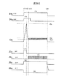
図3〜5は、インジェクタ13(ソレノイド13a)を駆動制御する各部の制御信号、および、インジェクタ駆動電流波形(ソレノイド電流波形)を示した図である。
インジェクタを駆動する電流波形(ソレノイド電流波形)は、図3〜5に示す波形1〜3の3種類存在し、運転状態によりCPU24からSPI通信により切換え可能としている。
まず、インジェクタ駆動電流(ソレノイド駆動電流)13b(図2参照)について説明する。以下、シンク用第三スイッチ素子36について説明するが、シンク用第四スイッチ素子37についても同様である。
【0036】
図3の波形1では、インジェクタ駆動電流13bに示す通り、開弁電流と2段の保持電流から構成される。タイミングt1は、インジェクタ13の噴射開始タイミングであり、CPU24からの開弁信号24a、および、保持信号24bの論理積が成立したとき、第一スイッチ素子33、および、第三スイッチ素子36をオンさせ、第一スイッチ素子33→インジェクタ13→第三スイッチ素子36→グランドにインジェクタ駆動電流13bを流し、所定電流値40aに到達するまで、インジェクタ13に開弁のための駆動電流13bを供給し、インジェクタ13を開弁させる。
【0037】
このときのインジェクタ駆動電流13bは、第三スイッチ素子36に設定された電流検出素子で検出され、その検出値36yと開弁電流基準値40aが比較される。なお、第一スイッチ素子33、および、第三スイッチ素子36は、それぞれ制御部39からの制御信号33z、36zにより制御される。
【0038】
所定電流値40aに到達したタイミングt2では、第一スイッチ素子33をオフさせ、インジェクタ駆動電流13bは、インジェクタ13→第三スイッチ素子36→グランド→還流素子38→インジェクタ13の電流ループで電流を流しながら減少していく。
【0039】
タイミングt3では、所定値電流40b1までインジェクタ駆動電流13bが減少したら、第二スイッチ素子3を制御部39からの制御信号34zによりオンさせ、第二スイッチ素子34→逆流防止素子35→インジェクタ13→スイッチ素子346→グランドにインジェクタ駆動電流13bを流し、所定電流値40bに到達するまで第二スイッチ素子34をオンする。このときのインジェクタ駆動電流13bは、第三スイッチ素子36に設定された電流検出素子で検出され、その検出値36yと保持電流1の基準値40b、および、保持電流1の基準値40bにより決定する保持電流1のヒス基準値40b1と比較される。
【0040】
開弁信号24aがオフするまでのt3〜t4区間は、前記第二スイッチ素子34のオン、オフ動作を繰り返し、所定電流値40b1〜40bの間でインジェクタ駆動電流13bの定電流制御を行う。なお、本実施形態の定電流制御値は、高燃圧時の開弁電流のみでは、インジェクタ13が開弁しないときの吸引力アップを目的としており、インジェクタ13内のソレノイド13aの起磁力を大きし、インジェクタ13を開弁させるために、その定電流値は比較的大きな値となる。
【0041】
タイミングt4では、開弁信号24aのオフにより、定電流制御値をインジェクタ13の開弁保持状態を維持する程度まで電流値を小さくする。タイミングt4、即ち、開弁信号24aがオフしたとき、第二スイッチ素子34をオフさせ、インジェクタ駆動電流13bは、インジェクタ13→第三スイッチ素子36→グランド→還流素子38→インジェクタ13の電流ループで電流を流しながら減少していく。
【0042】
タイミングt5では、所定値電流40c1までインジェクタ駆動電流13bが減少したら、第二スイッチ素子34を制御部39からの制御信号34zによりオンさせ、第二スイッチ素子34→逆流防止素子35→インジェクタ13→第三スイッチ素子36→グランドにインジェクタ駆動電流13bを流し、所定電流値40cに到達するまで第二スイッチ素子34をオンする。このときのインジェクタ駆動電流13bは、第三スイッチ素子36に設定された電流検出素子で検出され、その検出値36yと保持電流2の基準値40c、および、保持電流2の基準値40cにより決定する保持電流2のヒス基準値40c1と比較される。
保持信号24bがオフするまでのt5〜t6区間は、前述の第二スイッチ素子34のオン、オフ動作を繰り返し、所定電流値40c1〜40cの間でインジェクタ駆動電流13bの定電流制御を行う。
【0043】
タイミングt6では、保持信号24bのオフにより、インジェクタ駆動電流13bを遮断し、燃料噴射を停止する。なお、タイミングt6では、第二スイッチ素子34および第三スイッチ素子36をオフさせ、即ち、インジェクタ13の上下流を制御する双方のスイッチ素子を停止し、インジェクタ駆動電流13bを素早く減少させ、インジェクタ13の燃料噴射は、保持信号24bに連動して停止する。
【0044】
図4の波形2では、インジェクタ駆動電流13bが示すように、開弁電流と1段の保持電流から構成される。タイミングt11は、インジェクタ13の噴射開始タイミングである。CPU24からの開弁信号24a、および、保持信号24bの論理積が成立したとき、第一スイッチ素子33、および、第三スイッチ素子36をオンさせ、第一スイッチ素子33→インジェクタ13→第三スイッチ素子36→グランドにインジェクタ駆動電流13bを流し、所定電流値40aに到達するまで、インジェクタ13に開弁電流13bを供給し、インジェクタ13を開弁させる。このときのインジェクタ駆動電流13bは、第三スイッチ素子36に設定された電流検出素子で検出され、その検出値36yと開弁電流基準値40aが比較される。
【0045】
所定電流値40aに到達したタイミングt12では、第一スイッチ素子33をオフさせ、インジェクタ駆動電流13bは、インジェクタ13→第三スイッチ素子36→グランド→還流素子38→インジェクタ13の電流ループで電流を流しながら減少していく。
【0046】
タイミングt13では、所定値電流40c1までインジェクタ駆動電流13bが減少したら、第二スイッチ素子34を制御部39からの制御信号34zによりオンさせ、第二スイッチ素子34→逆流防止素子35→インジェクタ13→第三スイッチ素子36→グランドにインジェクタ駆動電流13bを流し、所定電流値40cに到達するまで第二スイッチ素子34をオンする。このときのインジェクタ駆動電流13bは、第三スイッチ素子36に設定された電流検出素子で検出され、その検出値36yと保持電流2の基準値40c、および、保持電流2の基準値40cにより決定する保持電流1のヒス基準値40c1と比較される。保持信号24bがオフするまでのt13〜t14区間は、前記の第二スイッチ素子34のオン、オフ動作を繰り返し、所定電流値40c1〜40cの間でインジェクタ駆動電流13bの定電流制御を行う。なお、本実施形態の定電流制御値は、前記図3のt5〜t6区間と同じ考え方である。即ち、インジェクタ13の開弁状態を保持することを目的とする。
【0047】
タイミングt14では、保持信号24bのオフにより、インジェクタ駆動電流13bを遮断し、燃料噴射を停止する。なお、タイミングt14では、第二スイッチ素子34および第三スイッチ素子36をオフさせ、即ち、インジェクタ13の上下流を制御する双方のスイッチ素子を停止し、インジェクタ駆動電流13bを素早く減少させ、インジェクタ13の燃料噴射は、保持信号24bに連動して停止する。
波形2では、開弁信号24aは、開弁電流開始許可条件にしか使用していないので、開弁信号24aのオフタイミングは、タイミングt12〜t14の間であればよい。また、波形2と波形1の違いは、保持電流1の有無である。
【0048】
図5の波形3では、インジェクタ駆動電流13bが示しように、開弁電流と1段の保持電流から構成される。なお、波形2との違いは、開弁電流と保持電流の切換え時、下流第三スイッチ素子36をオフするか否かである。
タイミングt21は、インジェクタ13の噴射開始タイミングである。CPU24からの開弁信号24a、および、保持信号24bの論理積が成立したとき、第一スイッチ素子33、および、第三スイッチ素子36をオンさせ、第一スイッチ素子33→インジェクタ13→第三スイッチ素子36→グランドにインジェクタ駆動電流13bを流し、所定電流値40aに到達するまで、インジェクタ13にインジェクタ駆動電流13bを供給し、インジェクタ13を開弁させる。このときのインジェクタ駆動電流13bは、第三スイッチ素子36に設定された電流検出素子で検出され、その検出値36yと開弁電流の基準値40aと比較される。
所定基準値40aに到達したタイミングt22では、第一スイッチ素子33、および、第三スイッチ素子36をオフさせ、インジェクタ駆動電流13bを素早く減少させる。 このとき、第三スイッチ素子36には、t22〜t23間のインジェクタ駆動電流電流13b × 電圧36aの損失が発生し、インジェクタ駆動電流電流13bは、開弁電流40aであるため大きく、そのため、回路損失は、非常に大きくなる。
【0049】
タイミングt23では、所定値電流40c1までインジェクタ駆動電流13bが減少したら、第二スイッチ素子34および第三スイッチ素子36を制御部39からの制御信号34z、36zによりそれぞれオンさせ、第二スイッチ素子34→逆流防止素子35→インジェクタ13→第三スイッチ素子36→グランドにインジェクタ駆動電流13bを流し、所定電流値40cに到達するまで第二スイッチ素子34をオンする。このときのインジェクタ駆動電流13bは、第三スイッチ素子36に設定された電流検出素子で検出され、その検出値36yと保持電流2の基準値40c、および、保持電流2の基準値40cにより決定する保持電流1のヒス基準値40c1と比較される。保持信号24bがオフするまでのt23〜t24区間は、前記の第二スイッチ素子34のオン、オフ動作を繰り返し、所定電流値40c1〜40cの間でインジェクタ駆動電流13bの定電流制御を行う。なお、本定電流制御値は、図3のt5〜t6、および、図4のt13〜t14区間と同じ考え方である。即ち、インジェクタ13の開弁状態を保持することを目的とする。
【0050】
タイミングt24では、保持信号24bのオフにより、インジェクタ駆動電流13bを遮断し、燃料噴射を停止する。なお、タイミングt14では、第二スイッチ素子34および第三スイッチ素子36をオフさせ、即ち、インジェクタ13の上下流を制御する双方のスイッチ素子を停止し、インジェクタ駆動電流13bを素早く減少させ、インジェクタ13の燃料噴射は、保持信号24bに連動して停止する。
【0051】
波形3では、波形2と同様、開弁信号24aは、開弁電流開始許可条件にしか使用していない。よって、開弁信号24aのオフタイミングは、タイミングt22〜t24の間であればよい。また、波形3と波形2の違いは、開弁電流から保持電流の切換え時にインジェクタ下流の第三スイッチ素子36のオフ有無による。以上、図3〜5を参照して、インジェクタ13に供給する電流波形1〜3の各々について記述したが、それぞれメリット、デメリットがある。
【0052】
燃料噴射量有効最小パルス幅特性(Qmin特性)は、電流波形により下記の特性順となる。
波形3 > 波形2 > 波形1
即ち、Qmin特性が重要となる運転領域、例えば、内燃機関低回転時は、波形3で、インジェクタを制御する必要がある。
【0053】
インジェクタ13のプランジャーの吸引力特性は、電流波形により下記の特性順となる。
波形1 > 波形2 = 波形3
即ち、高燃圧時の大きな吸引力が必要とするときは、波形1でインジェクタを制御する必要がある。
【0054】
また、インジェクタ制御回路31の回路損失は、下記の順で低損失となる。
波形2 > 波形1 > 波形3
即ち、波形2が回路損失ミニマムとなるため、前述Qmin特性が重要となる運転領域、または、高燃圧時の大きな吸引力が必要とするとき以外は、波形2のインジェクタ駆動電流波形で制御するのがよい。また、コントロールユニット15の全体損失を低くする意味でも必要である。
【0055】
前記のように、インジェクタ駆動電流13bの電流波形は、各運転状態に最適な波形に切換え、インジェクタ13の特性、および、インジェクタ制御回路31の損失低減を両立させる。
【0056】
図6は、本実施形態におけるインジェクタ駆動電流13bを切換えるSPI通信部42の内部ブロック図である。SPI通信線24cは、図2では1本線として記載されているが、CS線24c1、DIN線24c2、SCK線24c3、DOUT線24c4の4本線から構成される。
【0057】
SPI通信では、CPU24のCS線24c1から信号が入力されている間(信号がLOWの間)、CPU4とインジェクタ制御部31内のSPI部42を結ぶシリアル通信の送受信が行われる。まず、CS線24c1から信号が入力されると、予めラッチ回路63に格納されていた8bitデータを確定し、シフトレジスタ62にコピーされる。本実施形態では、ラッチ回路63、および、DOUT線24c4の信号については、特に記述しない。
【0058】
その後、送受信されるデータは、CPU24により送られるCSK線24c3の信号に基づいて伝送される。CPU24とSPI部42を結ぶシリアル通信は、8ビットのシフトレジスタ62で構成されており、CPU24のDIN線24c2の信号は、ここに格納される。同時に、シフトレジスタ62に格納されていた送信データが、CSK線24c3の信号によりDOUT線24c4の信号として掃きだされる。これらの動作は、CPU24からのクロックのSCK線24c3の信号の立上がり、または、立下がりエッジに同期して1ビットづつ行われる。
【0059】
その後、シフトレジスタ62に格納されているデータは、CS線24c1の信号が終了するとき(HIGHになるとき)、レジスタ61へ移される。このとき、DIN線24c2の信号には、インジェクタ駆動電流波形を切換える司令値が含まれており、本実施形態では、3種類に切換え可能なことから8ビットのDIN線24c2の信号内に2ビット含まれていることになる。
【0060】
そして、受信したDIN線24c2の信号からインジェクタ駆動電流波形を切換える司令値を制御部39で抽出し、前述司令値に従い制御部39ではインジェクタ駆動電流13bを制御する。前記のSPI通信は、8ビットのシフトレジスタとして説明したが、何ビットのシフトレジスタ、例えば16ビットシフトレジタで構成されてもよい。
【0061】
図7は、SPI通信のビット割付けのマップを示している。
DIN線24c2の信号は、本実施形態では、8ビットで示され、インジェクタ駆動電流波形を切換えるビットとして2ビット割付けている。Bi5は、保持電流1の有無を切換えるビットである。Bi5=1のときは、保持電流1を有効、BI=0のときは、保持電流1を無効とする。即ち、Bi5=0のとき、保持電流が1段階となる。
【0062】
また、Bi6は、インジェクタ駆動電流波形の保持電流1を無効、即ち、Bi5=0のとき、有効であり、び6=1のときは、開弁電流から保持電流のときの第三スイッチ素子36のオフを有効とBi6=0のときは、開弁電流から保持電流のときの第三スイッチ素子36のオフを無効とする。
【0063】
即ち、インジェクタ駆動電流波形とDIN線24c2の信号の関係は、下記のようになる。
波形1 : (Bi5、Bi6)=(1,*) *はDon’t care
波形2 : (Bi5、Bi6)=(0,0)
波形3 : (Bi5、Bi6)=(0,1)
【0064】
図8は、本実施形態のインジェクタ駆動電流波形を切換える手段をCPU24内のソフトウェアで実現するソフトウェアのフローチャートである。
本タスクは、定時JOB、例えば、10ms毎に実施されることが一般的である。10msタスクからコールされ、スタートのステップS1から開始される。ステップS2では、現在インジェクタ噴射中有無を確認する。インジェクタ噴射中にインジェクタ駆動電流波形を切換えるとインジェクタ動作が異常となる。そこで、インジェクタ噴射中は、インジェクタ駆動電流波形を切換える手段をマスクし、即ち、ステップS9のENDにジャンプする。
【0065】
ステップS2で、インジェクタ噴射中でないことを確認すると、ステップS3へ遷移する。ステップS3では、現在の内燃機関運転状態がQmin特性重要な領域か否かを判断し、Qmin特性が重要な領域の場合は、ステップS5へ遷移する。
ステップS5では、インジェクタ駆動電流波形をQmin特性が優れている波形3に切換えるべく、(Bi5、Bi6)=(0,1)にセットする。
【0066】
ステップS3で、Qmin特性が重要な領域でない場合は、ステップS4へ遷移する。ステップS4では、現在の内燃機関運転状態において、高燃圧か否かを判断し、高燃圧の場合は、ステップS6へ遷移する。
ステップS6では、インジェクタ駆動電流波形を高燃圧時にインジェクタが開弁できるように、吸引力が優れている波形1に切換えるべく、(Bi5、Bi6)=(1,*)にセットする。ステップS4で、高燃圧でないことを判断した場合は、ステップS7へ遷移する。
【0067】
ステップS7では、Qmin特性が重要でなく、且つ、高燃圧でないために大きな吸引力が必要でない場合に、回路損失をミニマムとするために、波形2に切換えるべく、(Bi5、Bi6)=(0,0)にセットする。
ステップS8では、前記ステップS5、S6、S7でセットしたインジェクタ駆動電流波形をSPI通信により、インジェクタ制御回路31に送信する。そしてSPI部42を介して、制御部39にインジェクタ駆動電流波形をセットする。
そして、燃料噴射量は、開弁信号24a、および、保持信号24bのパルス幅に基づき決定され、インジェクタ13を制御して、内燃機関1を最適制御する。
【0068】
以上、本発明の一実施形態について記述したが、本発明は前記実施形態に限定されるものではなく、特許請求項の範囲に記載された発明の精神を逸脱しない範囲で設計において種種の変更ができるものである。
【0069】
【発明の効果】
以上の発明から理解されるように、本発明の燃料噴射装置を備えた内燃機関の制御装置は、インジェクタの小型化による該インジェクタのソレノイドのインダクタンスが小さい場合における高燃圧時でも、インジェクタを最適に制御でき、最小燃料噴射量特性を良好に維持することができる。また、内燃機関の燃料供給装置の損失を小さくすることができる。
【図面の簡単な説明】
【図1】本発明の内燃機関の制御装置の一実施形態のが適用されている内燃機関の制御システムの全体構成図。
【図2】図1の内燃機関の制御装置のソレノイド制御回路の構成図。
【図3】図2のソレノイド制御回路によって形成されるインジェクタ駆動の第一電流波形を示した図。
【図4】図2のソレノイド制御回路によって形成されるインジェクタ駆動の第二電流波形を示した図。
【図5】図2のソレノイド制御回路によって形成されるインジェクタ駆動の第三電流波形を示した図。
【図6】図2のソレノイド制御回路のSPI部の内部ブロック図。
【図7】図6のSPI部のビット割付けを示す図。
【図8】図1の内燃機関の制御装置の制御フローチャート。
【符号の説明】
1…内燃機関、1a…シリンダ、2…燃焼室、12…燃料ポンプ、13…インジェクタ、13a…ソレノイド、14…可変燃圧プレッシャレギュレータ、15…コントロールユニット、16…クランク角センサ、17…点火コイル、21…燃圧センサ、24…CPU、24a…インジェクタ開弁信号、24b…インジェクタ保持信号、24c…SPI通信線、31…ソレノイド制御回路、32…昇圧回路、33…開弁用上流の第一スイッチ素子、34…保持用上流の第二スイッチ素子、35…電流逆流防止素子、36…シンク用の第三スイッチ素子、38…還流素子、39…制御部、40…基準電流生成部、42…SPI部[0001]
BACKGROUND OF THE INVENTION
The present invention relates to a control device for an internal combustion engine, and more particularly, to a control device for controlling a current waveform applied to a solenoid of an internal combustion engine provided with a fuel injection device having a solenoid.
[0002]
[Prior art]
2. Description of the Related Art Conventionally, a fuel injection valve (injector) that injects fuel into a combustion chamber of an internal combustion engine includes a plunger, a solenoid that urges the plunger in a valve opening direction, and the plunger closed in the fuel injection valve. And a fuel pressure supplied to the fuel injection valve is in a high pressure state, and the high pressure fuel pressure biases the plunger in the valve closing direction. .
[0003]
In addition, the current applied to the solenoid (injector) is powered by a battery, and the applied drive current has a single current waveform, which is from the fuel injection valve to the combustion chamber of the internal combustion engine. The fuel injection control is performed by applying a current of the single current waveform based on an application signal from the control device to the solenoid of the fuel injection valve.
[0004]
For example, in the solenoid application control for fuel injection of the fuel injection valve described in Japanese Patent Application Laid-Open Nos. 11-13519 and 11-343910, the drive current waveform of the fuel injection valve (injector) is one-stage open. It has a single drive current waveform in two stages consisting of a valve signal and a single hold signal, and changes the fuel injection pulse width based on the operating state of the internal combustion engine to inject it into the combustion chamber of the internal combustion engine The combustion of the internal combustion engine is controlled by controlling the injection amount of the supplied fuel.
[0005]
[Problems to be solved by the invention]
By the way, in recent years, a fuel injection valve (injector) installed in an internal combustion engine has been strongly required to be downsized due to various requirements. However, when the fuel injection valve (injector) is reduced in size, the inductance value of the solenoid built in the fuel injection valve (injector) becomes small, and the conventional technology applied to the solenoid as described above. In this case, the magnetomotive force may be small, and in this case, the attractive force of the plunger built in the fuel injection valve (injector) by the solenoid is small. In particular, when the supplied fuel is in a high pressure state, sometimes the plunger cannot be attracted by the magnetomotive force of the solenoid, and fuel injection from the fuel injection valve may not be possible.
[0006]
In addition, the minimum amount of fuel that can be injected by the fuel injection valve (injector) in one injection, that is, the minimum fuel injection amount characteristic in one fuel injection of the fuel injection valve is also important. The minimum fuel injection amount characteristic is required particularly during stratified lean combustion, and the minimum fuel injection amount characteristic is important for fuel consumption and emission characteristics.
[0007]
The present invention has been made in view of the above points, and the object of the present invention is to optimally inject fuel even when the inductance value of the solenoid is reduced by downsizing the fuel injection valve (injector), and Another object of the present invention is to provide a control device for an internal combustion engine provided with a fuel injection device having excellent minimum fuel injection amount characteristics.
[0008]
[Means for Solving the Problems]
In order to achieve the above object, a control device for an internal combustion engine of the present invention is basically a control device for an internal combustion engine provided with a fuel injection device having a solenoid, and the control device is an operating state of the internal combustion engine. Detecting means, means for calculating a fuel injection pulse width based on the operating state, and solenoid control means for controlling the solenoid, wherein the solenoid control means controls the solenoid based on the fuel injection pulse width. The current is controlled by supplying current to the solenoid until a large predetermined current value is reached, and after the valve opening current reaches the predetermined current value, the solenoid is opened. To keep it in a state,Fuel injection amount effective minimum pulse width characteristics in the operating state of the internal combustion engine ( Qmin Judgment whether or not (characteristic) is an important areaThe solenoid is controlled by switching and supplying one of a plurality of small current holding currents having different current waveforms.
[0009]
Further, according to a specific aspect of the control device for an internal combustion engine of the present invention, the solenoid control means includes a booster circuit that boosts power from a battery, a first switch circuit that supplies power from the booster circuit to the solenoid, A second switch circuit that supplies power from the battery to the solenoid; a third switch circuit that sinks current from the solenoid in a ground direction; and the first switch circuit and the second switch circuit that are off. And a flywheel circuit that returns current to ground via the solenoid and the third switch circuit.
[0010]
Further, according to another specific aspect of the control device for an internal combustion engine of the present invention, the plurality of current waveforms supplied to the solenoid are a first current waveform of one-stage valve opening and two-stage holding, a first-stage valve opening and one-stage holding circuit. There are three types of current waveforms: a two-current waveform and a third current waveform that is different from the second current waveform and that is one-stage valve opening and one-stage holding.
[0011]
The control device for an internal combustion engine of the present invention configured as described above can optimally control the injector even when the injector solenoid is small due to the small size of the injector, even at high fuel pressure, and the minimum fuel injection amount characteristic is good. Can be maintained.
[0012]
According to another specific aspect of the control device for an internal combustion engine of the present invention, the current waveform control means is configured to supply a valve opening current until reaching a large predetermined current value in forming the first current waveform. The first switch circuit and the third switch circuit are turned on, and then the first switch circuit is turned off and the second switch circuit is turned on to supply a large holding current that keeps the valve open for a predetermined time by the flywheel circuit. Further, the second switch circuit is controlled to be turned on / off to supply a small holding current for holding the valve open state by the flywheel circuit.
[0013]
Furthermore, according to still another specific aspect of the control device for an internal combustion engine of the present invention, the current waveform control means is configured to supply a valve opening current until reaching a large predetermined current value in forming the second current waveform. The first switch circuit and the second switch circuit are turned on, and then the first switch circuit is turned off and the second switch circuit is turned on / off in order to supply a small holding current for holding the valve open state by the flywheel circuit. The control apparatus for an internal combustion engine according to
[0014]
Furthermore, according to still another specific aspect of the control device for an internal combustion engine of the present invention, the current waveform control means supplies a valve opening current until a large predetermined current value is reached in forming the third current waveform. The first switch circuit and the third switch circuit are turned on, and then the first switch circuit and the third switch circuit are turned off in order to speed up the switching time from the valve opening current to the holding current. The circuit is characterized in that the third switch circuit is turned on and the second switch circuit is turned on / off to supply a small holding current for holding the valve open state by the circuit.
[0015]
Furthermore, according to still another specific aspect of the control device for an internal combustion engine of the present invention, the current waveform control means includes two types of the three types of current waveforms supplied to the solenoid based on an operating state of the internal combustion engine. It is characterized by switching the above.
[0016]
Furthermore, another specific aspect of the control device for an internal combustion engine of the present invention is the control device.ButAnd a means for controlling the pressure of the fuel supplied to the fuel injection device, and a means for detecting the fuel pressure.,The control device is a pressure value of the fuel.But,During the fuel injection, switching of the waveform of the current supplied to the solenoid is prohibited.
[0017]
Still further, according to still another specific aspect of the control device for an internal combustion engine of the present invention, the control device includes a calculation device that determines an operating state of the internal combustion engine, and the calculation device, the current waveform control means, Is characterized by serial communication as a medium.
[0018]
DETAILED DESCRIPTION OF THE INVENTION
Hereinafter, an embodiment of a control device for an internal combustion engine provided with a fuel injection device of the present invention will be described in detail with reference to the accompanying drawings.
[0019]
FIG. 1 is a diagram illustrating an overall configuration of an internal combustion engine system to which an internal combustion engine control device including a fuel injection device according to the present embodiment is applied. In FIG. 1, an
[0020]
The air sucked into the
[0021]
On the other hand, fuel such as gasoline is sucked and pressurized from the
[0022]
The variable fuel pressure regulator 14 is controlled by the
[0023]
Further, a
[0024]
The
[0025]
The
[0026]
FIG. 2 shows a control circuit configuration of the
[0027]
In normal operation, in order to open the
[0028]
The
[0029]
Further, in the
[0030]
The third and
[0031]
In FIG. 2, the
[0032]
The reference
[0033]
The
[0034]
The interface between the
[0035]
3 to 5 are diagrams showing the control signals of the respective parts that drive and control the injector 13 (
There are three types of current waveforms (solenoid current waveforms) for driving the injector, which are
First, the injector drive current (solenoid drive current) 13b (see FIG. 2) will be described. The sink
[0036]
As shown by the injector drive current 13b, the
[0037]
The injector drive current 13b at this time is detected by the current detection element set in the
[0038]
At the timing t2 when the predetermined
[0039]
At the timing t3, when the injector drive current 13b decreases to the predetermined current 40b1, the
[0040]
During the period from t3 to t4 until the
[0041]
At timing t4, the current value is reduced to such an extent that the constant current control value is maintained in the valve-opening holding state of the
[0042]
At timing t5, when the injector drive current 13b decreases to the predetermined current 40c1, the second switch element 34 is turned on by the
During the period from t5 to t6 until the holding
[0043]
At timing t6, the
[0044]
In the
[0045]
At the timing t12 when the predetermined
[0046]
At timing t13, when the injector drive current 13b decreases to the predetermined current 40c1, the second switch element 34 is turned on by the
[0047]
At timing t14, the
In the
[0048]
In the
Timing t21 is the injection start timing of the
At timing t22 when the
[0049]
At timing t23, when the injector drive current 13b decreases to the predetermined value current 40c1, the second switch element 34 and the
[0050]
At timing t24, the injector driving current 13b is cut off by stopping the holding
[0051]
In the
[0052]
The fuel injection amount effective minimum pulse width characteristic (Qmin characteristic) is in the following characteristic order according to the current waveform.
That is, it is necessary to control the injector with the
[0053]
The attractive force characteristic of the plunger of the
That is, when a large suction force at high fuel pressure is required, it is necessary to control the injector with the
[0054]
Further, the circuit loss of the
That is, since
[0055]
As described above, the current waveform of the injector drive current 13b is switched to a waveform that is optimal for each operation state, and both the characteristics of the
[0056]
FIG. 6 is an internal block diagram of the
[0057]
In the SPI communication, while a signal is input from the CS line 24c1 of the CPU 24 (when the signal is LOW), serial communication is transmitted and received between the
[0058]
Thereafter, the transmitted / received data is transmitted based on the signal of the CSK line 24c3 sent by the
[0059]
Thereafter, the data stored in the
[0060]
A command value for switching the injector drive current waveform is extracted from the received signal on the DIN line 24c2 by the
[0061]
FIG. 7 shows a map of bit allocation for SPI communication.
In this embodiment, the signal of the DIN line 24c2 is represented by 8 bits, and 2 bits are assigned as bits for switching the injector drive current waveform. Bi5 is a bit for switching the presence or absence of the holding current 1. When Bi5 = 1, holding current 1 is valid, and when BI = 0, holding current 1 is invalid. That is, when Bi5 = 0, the holding current becomes one stage.
[0062]
Bi6 is invalid when the holding current 1 of the injector drive current waveform is invalid, that is, when Bi5 = 0, and when 6 = 1, the
[0063]
That is, the relationship between the injector drive current waveform and the signal on the DIN line 24c2 is as follows.
Waveform 1: (Bi5, Bi6) = (1, *) * is Don't care
Waveform 2: (Bi5, Bi6) = (0, 0)
Waveform 3: (Bi5, Bi6) = (0, 1)
[0064]
FIG. 8 is a software flowchart for realizing the means for switching the injector drive current waveform of the present embodiment by software in the
This task is generally performed every scheduled job, for example, every 10 ms. It is called from a 10 ms task and is started from the start step S1. In step S2, it is confirmed whether or not the injector is currently being injected. If the injector drive current waveform is switched during injector injection, the injector operation becomes abnormal. Therefore, during injector injection, the means for switching the injector drive current waveform is masked, that is, the process jumps to END in step S9.
[0065]
If it is confirmed in step S2 that the injector is not being injected, the process proceeds to step S3. In step S3, it is determined whether or not the current operating state of the internal combustion engine is a region in which the Qmin characteristic is important.
In step S5, (Bi5, Bi6) = (0, 1) is set in order to switch the injector drive current waveform to
[0066]
If the Qmin characteristic is not an important region in step S3, the process proceeds to step S4. In step S4, it is determined whether or not the fuel pressure is high in the current operating state of the internal combustion engine. If the fuel pressure is high, the process proceeds to step S6.
In step S6, the injector drive current waveform is set to (Bi5, Bi6) = (1, *) so as to switch to the
[0067]
In step S7, when the Qmin characteristic is not important and a large suction force is not required because the fuel pressure is not high, in order to minimize the circuit loss, (Bi5, Bi6) = (0 , 0).
In step S8, the injector drive current waveform set in steps S5, S6, and S7 is transmitted to the
The fuel injection amount is determined based on the pulse widths of the
[0068]
Although one embodiment of the present invention has been described above, the present invention is not limited to the above-described embodiment, and various changes in design can be made without departing from the spirit of the invention described in the claims. It can be done.
[0069]
【The invention's effect】
As can be understood from the above invention, the control device for an internal combustion engine provided with the fuel injection device of the present invention optimizes the injector even at high fuel pressure when the inductance of the solenoid of the injector is small due to the miniaturization of the injector. The minimum fuel injection amount characteristic can be maintained satisfactorily. Further, the loss of the fuel supply device for the internal combustion engine can be reduced.
[Brief description of the drawings]
FIG. 1 is an overall configuration diagram of an internal combustion engine control system to which an embodiment of a control apparatus for an internal combustion engine of the present invention is applied.
2 is a configuration diagram of a solenoid control circuit of the control device for the internal combustion engine of FIG. 1;
FIG. 3 is a diagram showing a first current waveform of the injector drive formed by the solenoid control circuit of FIG. 2;
4 is a diagram showing a second current waveform of the injector drive formed by the solenoid control circuit of FIG. 2; FIG.
FIG. 5 is a diagram showing a third current waveform of the injector drive formed by the solenoid control circuit of FIG. 2;
6 is an internal block diagram of an SPI unit of the solenoid control circuit of FIG. 2;
7 is a diagram showing bit allocation of the SPI unit in FIG. 6;
FIG. 8 is a control flowchart of the control device for the internal combustion engine of FIG. 1;
[Explanation of symbols]
DESCRIPTION OF
Claims (10)
該ソレノイド制御手段は、前記燃料噴射パルス幅に基づき前記ソレノイドに電流を供給して制御するものであって、最初、大きな所定電流値に至るまで前記ソレノイドに開弁電流を供給し、該開弁電流が所定電流値に至った後は、前記ソレノイドを開弁状態に保持するべく、前記内燃機関の運転状態の燃料噴射量有効最小パルス幅特性( Qmin 特性)が重要な領域か否かを判断して複数の異なる電流波形の小さな電流値の保持電流の内の一つを切換え供給して前記ソレノイドを制御することを特徴とする内燃機関の制御装置。Oite to the control apparatus for an internal combustion engine having a fuel injection system having a solenoid, the control device includes means for detecting the operating state of the internal combustion engine, means for calculating a fuel injection pulse width on the basis of the operating conditions, the Solenoid control means for controlling the solenoid, and
The solenoid control means controls the solenoid by supplying a current to the solenoid based on the fuel injection pulse width, and first supplies a valve opening current to the solenoid until a large predetermined current value is reached. After the current reaches a predetermined current value, it is determined whether or not the fuel injection amount effective minimum pulse width characteristic ( Qmin characteristic) in the operating state of the internal combustion engine is an important region in order to keep the solenoid valve open. A control device for an internal combustion engine, wherein the solenoid is controlled by switching and supplying one of a plurality of holding currents having small current values of different current waveforms.
Priority Applications (3)
| Application Number | Priority Date | Filing Date | Title |
|---|---|---|---|
| JP2001302694A JP4037632B2 (en) | 2001-09-28 | 2001-09-28 | Control device for internal combustion engine provided with fuel injection device |
| US10/101,207 US6684862B2 (en) | 2001-09-28 | 2002-03-20 | Controller for internal combustion engine having fuel injection system |
| EP02006548A EP1298305B1 (en) | 2001-09-28 | 2002-03-20 | Controller for internal combustion engine having fuel injection system |
Applications Claiming Priority (1)
| Application Number | Priority Date | Filing Date | Title |
|---|---|---|---|
| JP2001302694A JP4037632B2 (en) | 2001-09-28 | 2001-09-28 | Control device for internal combustion engine provided with fuel injection device |
Publications (2)
| Publication Number | Publication Date |
|---|---|
| JP2003106200A JP2003106200A (en) | 2003-04-09 |
| JP4037632B2 true JP4037632B2 (en) | 2008-01-23 |
Family
ID=19122891
Family Applications (1)
| Application Number | Title | Priority Date | Filing Date |
|---|---|---|---|
| JP2001302694A Expired - Lifetime JP4037632B2 (en) | 2001-09-28 | 2001-09-28 | Control device for internal combustion engine provided with fuel injection device |
Country Status (3)
| Country | Link |
|---|---|
| US (1) | US6684862B2 (en) |
| EP (1) | EP1298305B1 (en) |
| JP (1) | JP4037632B2 (en) |
Families Citing this family (30)
| Publication number | Priority date | Publication date | Assignee | Title |
|---|---|---|---|---|
| JP2004092573A (en) * | 2002-09-03 | 2004-03-25 | Hitachi Ltd | Fuel injection device and control method |
| JP3894088B2 (en) * | 2002-10-07 | 2007-03-14 | 株式会社日立製作所 | Fuel supply device |
| ITTO20030939A1 (en) * | 2003-11-25 | 2005-05-26 | Fiat Ricerche | CONTROL DEVICE FOR INDUCTIVE ELECTRO-ACTUATORS. |
| ITTO20030940A1 (en) * | 2003-11-25 | 2005-05-26 | Fiat Ricerche | COMMAND DEVICE OF ELECTRO-INJECTORS OF A COMMON FUEL INJECTION SYSTEM WITH A COMMON COLLECTOR FOR AN INTERNAL COMBUSTION ENGINE. |
| US20060275137A1 (en) * | 2005-06-01 | 2006-12-07 | Visteon Global Technologies, Inc. | Fuel pump boost system |
| JP2007170204A (en) * | 2005-12-19 | 2007-07-05 | Kokusan Denki Co Ltd | Fuel injection device for internal combustion engine |
| JP4353211B2 (en) * | 2006-07-11 | 2009-10-28 | 株式会社日立製作所 | Controller with built-in communication function |
| JP4474423B2 (en) | 2007-01-12 | 2010-06-02 | 日立オートモティブシステムズ株式会社 | Internal combustion engine control device |
| JP2008291778A (en) * | 2007-05-25 | 2008-12-04 | Denso Corp | Solenoid valve control device |
| JP4917556B2 (en) * | 2008-01-07 | 2012-04-18 | 日立オートモティブシステムズ株式会社 | Fuel injection control device for internal combustion engine |
| JPWO2009154214A1 (en) * | 2008-06-19 | 2011-12-01 | ボッシュ株式会社 | Fuel injection valve control device, control method, and control program |
| JP4815502B2 (en) | 2009-03-26 | 2011-11-16 | 日立オートモティブシステムズ株式会社 | Control device for internal combustion engine |
| JP5058239B2 (en) * | 2009-10-30 | 2012-10-24 | 日立オートモティブシステムズ株式会社 | Fuel injection control device for internal combustion engine |
| DE102009056802B4 (en) | 2009-12-03 | 2019-05-29 | Robert Bosch Gmbh | Control electronics for an electromagnetically actuated valve for operating a hydrostatic displacement unit |
| FR2955516B1 (en) * | 2010-01-26 | 2012-04-20 | Prospection & Inventions | METHOD FOR CONTROLLING A TOOL WITH INTERNAL COMBUSTION ENGINE AND THE TOOL SO CONTROL |
| JP5198496B2 (en) | 2010-03-09 | 2013-05-15 | 日立オートモティブシステムズ株式会社 | Engine control unit for internal combustion engines |
| JP5300787B2 (en) * | 2010-05-31 | 2013-09-25 | 日立オートモティブシステムズ株式会社 | Internal combustion engine control device |
| JP5358621B2 (en) | 2011-06-20 | 2013-12-04 | 日立オートモティブシステムズ株式会社 | Fuel injection device |
| US9103295B2 (en) | 2012-08-13 | 2015-08-11 | Continental Automotive Systems, Inc. | Current controller having programmable current-control parameters and hardware-implemented support functions |
| JP5975899B2 (en) * | 2013-02-08 | 2016-08-23 | 日立オートモティブシステムズ株式会社 | Drive device for fuel injection device |
| US20160115921A1 (en) * | 2013-05-24 | 2016-04-28 | International Engine Intellectual Property Company , Llc | Injector waveform |
| US9347395B2 (en) * | 2013-08-22 | 2016-05-24 | GM Global Technology Operations LLC | Method for improving closely-spaced multiple-injection performance from solenoid actuated fuel injectors |
| JP5875559B2 (en) * | 2013-08-30 | 2016-03-02 | 日立オートモティブシステムズ株式会社 | Drive circuit for fuel injection device |
| EP2918816B1 (en) * | 2014-03-14 | 2017-09-06 | Continental Automotive GmbH | Fuel injector |
| US10401398B2 (en) | 2017-03-03 | 2019-09-03 | Woodward, Inc. | Fingerprinting of fluid injection devices |
| JP7110736B2 (en) * | 2018-05-31 | 2022-08-02 | 株式会社デンソー | Control device for fuel injection valve and fuel injection system |
| US10900391B2 (en) * | 2018-06-13 | 2021-01-26 | Vitesco Technologies USA, LLC. | Engine control system and method for controlling activation of solenoid valves |
| US20200025122A1 (en) * | 2018-07-17 | 2020-01-23 | Continental Automotive Systems, Inc. | Engine control system and method for controlling activation of solenoid valves |
| KR20210104317A (en) * | 2020-02-17 | 2021-08-25 | 현대자동차주식회사 | Apparatus and method for controlling fuel injection for improving the deviation of opening duration of injector |
| US11795886B2 (en) * | 2021-12-13 | 2023-10-24 | Caterpillar Inc. | Reduced energy waveform for energizing solenoid actuator in fuel injector valve |
Family Cites Families (19)
| Publication number | Priority date | Publication date | Assignee | Title |
|---|---|---|---|---|
| JPS5681232A (en) * | 1979-12-04 | 1981-07-03 | Aisan Ind Co Ltd | Valve driving mechanism and its control for injector |
| JPS5872646A (en) * | 1981-10-26 | 1983-04-30 | Toyota Motor Corp | Air-fuel ratio control method for internal-combustion engine |
| JPS60135646A (en) * | 1983-12-21 | 1985-07-19 | Ngk Spark Plug Co Ltd | Apparatus for generating signal for controlling fuel injection starting timing of fuel injection apparatus with valve operation controlling solenoid |
| US4922878A (en) * | 1988-09-15 | 1990-05-08 | Caterpillar Inc. | Method and apparatus for controlling a solenoid operated fuel injector |
| JPH033945A (en) * | 1989-05-31 | 1991-01-10 | Hitachi Ltd | Engine control device |
| JP3052572B2 (en) * | 1992-05-21 | 2000-06-12 | 株式会社デンソー | Fuel injection control device for internal combustion engine |
| JP3286371B2 (en) * | 1993-02-15 | 2002-05-27 | 本田技研工業株式会社 | Fuel injection control device for internal combustion engine |
| US5701870A (en) * | 1996-04-15 | 1997-12-30 | Caterpillar Inc. | Programmable fuel injector current waveform control and method of operating same |
| US5788154A (en) * | 1996-05-02 | 1998-08-04 | Caterpillar Inc. | Method of preventing cavitation in a fuel injector having a solenoid actuated control valve |
| JP3613885B2 (en) * | 1996-05-24 | 2005-01-26 | 国産電機株式会社 | Drive control method and drive control apparatus for injector for internal combustion engine |
| JPH1113519A (en) | 1997-06-19 | 1999-01-19 | Nissan Motor Co Ltd | Diagnostic device for drive control device of fuel injection valve, and diagnostic device therefor |
| DE19728840A1 (en) * | 1997-07-05 | 1999-01-07 | Bosch Gmbh Robert | Method and device for detecting a switching time of a solenoid valve |
| JP3871168B2 (en) | 1998-06-03 | 2007-01-24 | 株式会社日立製作所 | Engine fuel supply diagnostic apparatus, diagnostic method and fuel supply apparatus |
| JP3932474B2 (en) * | 1999-07-28 | 2007-06-20 | 株式会社日立製作所 | Electromagnetic fuel injection device and internal combustion engine |
| JP2001152940A (en) * | 1999-11-24 | 2001-06-05 | Mitsubishi Electric Corp | Fuel injection system |
| JP2001221121A (en) * | 2000-02-08 | 2001-08-17 | Hitachi Ltd | Electromagnetic fuel injection system and internal combustion engine having it mounted |
| JP4168567B2 (en) * | 2000-03-02 | 2008-10-22 | 株式会社デンソー | Solenoid valve drive |
| JP2001317394A (en) * | 2000-04-28 | 2001-11-16 | Mitsubishi Electric Corp | Fuel injection controller for cylinder injection engine |
| JP4110751B2 (en) * | 2001-06-18 | 2008-07-02 | 株式会社日立製作所 | Injector drive control device |
-
2001
- 2001-09-28 JP JP2001302694A patent/JP4037632B2/en not_active Expired - Lifetime
-
2002
- 2002-03-20 US US10/101,207 patent/US6684862B2/en not_active Expired - Lifetime
- 2002-03-20 EP EP02006548A patent/EP1298305B1/en not_active Expired - Lifetime
Also Published As
| Publication number | Publication date |
|---|---|
| EP1298305A2 (en) | 2003-04-02 |
| US6684862B2 (en) | 2004-02-03 |
| EP1298305A3 (en) | 2006-06-28 |
| JP2003106200A (en) | 2003-04-09 |
| US20030062029A1 (en) | 2003-04-03 |
| EP1298305B1 (en) | 2011-05-18 |
Similar Documents
| Publication | Publication Date | Title |
|---|---|---|
| JP4037632B2 (en) | Control device for internal combustion engine provided with fuel injection device | |
| JP5058239B2 (en) | Fuel injection control device for internal combustion engine | |
| US8751139B2 (en) | System, method, and apparatus for gas engine enhanced starting | |
| JPH08319865A (en) | Fuel injection control device for internal combustion engine of intra-cylinder injection type | |
| JP2010255444A (en) | Device and method for fuel injection control of internal combustion engine | |
| JP3827814B2 (en) | In-cylinder fuel control system | |
| JP2006144639A (en) | Engine control system | |
| US8453437B2 (en) | Secondary air supply device for internal combustion engine and control method of the secondary air supply device | |
| JP4244198B2 (en) | Fuel injection control method for internal combustion engine | |
| JP3828239B2 (en) | Control device for injector for fuel injection | |
| JPS61229957A (en) | Fuel controller | |
| JP4373474B2 (en) | Method of operating an internal combustion engine | |
| US6439190B1 (en) | Method for operating an internal combustion engine, especially of an automobile | |
| JP4637036B2 (en) | Control device for internal combustion engine | |
| JP4427783B2 (en) | Fuel injection control method for internal combustion engine | |
| JP2005113745A (en) | Fuel supply device for internal combustion engine | |
| JPS6035143A (en) | Engine | |
| JP2010133301A (en) | Method of controlling fuel injection of bi-fuel internal combustion engine | |
| JP2005299575A (en) | Fuel injection control method for internal combustion engine | |
| WO2016132708A1 (en) | Fuel injection control device | |
| JP2699122B2 (en) | Control device for internal combustion engine having assist air supply device | |
| KR100507188B1 (en) | a control method for fast engine start and emission reduction of engine in automobile | |
| GB2597062A (en) | Secondary air injection system and control method | |
| JPH0586942A (en) | Fuel feeding device of engine | |
| JP2005201073A (en) | Controller of internal combustion engine |
Legal Events
| Date | Code | Title | Description |
|---|---|---|---|
| A977 | Report on retrieval |
Free format text: JAPANESE INTERMEDIATE CODE: A971007 Effective date: 20060124 |
|
| A131 | Notification of reasons for refusal |
Free format text: JAPANESE INTERMEDIATE CODE: A131 Effective date: 20061205 |
|
| A521 | Request for written amendment filed |
Free format text: JAPANESE INTERMEDIATE CODE: A523 Effective date: 20070205 |
|
| A131 | Notification of reasons for refusal |
Free format text: JAPANESE INTERMEDIATE CODE: A131 Effective date: 20070417 |
|
| A521 | Request for written amendment filed |
Free format text: JAPANESE INTERMEDIATE CODE: A523 Effective date: 20070618 |
|
| TRDD | Decision of grant or rejection written | ||
| A01 | Written decision to grant a patent or to grant a registration (utility model) |
Free format text: JAPANESE INTERMEDIATE CODE: A01 Effective date: 20071023 |
|
| A61 | First payment of annual fees (during grant procedure) |
Free format text: JAPANESE INTERMEDIATE CODE: A61 Effective date: 20071101 |
|
| R151 | Written notification of patent or utility model registration |
Ref document number: 4037632 Country of ref document: JP Free format text: JAPANESE INTERMEDIATE CODE: R151 |
|
| FPAY | Renewal fee payment (event date is renewal date of database) |
Free format text: PAYMENT UNTIL: 20101109 Year of fee payment: 3 |
|
| FPAY | Renewal fee payment (event date is renewal date of database) |
Free format text: PAYMENT UNTIL: 20101109 Year of fee payment: 3 |
|
| S111 | Request for change of ownership or part of ownership |
Free format text: JAPANESE INTERMEDIATE CODE: R313111 |
|
| FPAY | Renewal fee payment (event date is renewal date of database) |
Free format text: PAYMENT UNTIL: 20101109 Year of fee payment: 3 |
|
| R350 | Written notification of registration of transfer |
Free format text: JAPANESE INTERMEDIATE CODE: R350 |
|
| FPAY | Renewal fee payment (event date is renewal date of database) |
Free format text: PAYMENT UNTIL: 20101109 Year of fee payment: 3 |
|
| FPAY | Renewal fee payment (event date is renewal date of database) |
Free format text: PAYMENT UNTIL: 20111109 Year of fee payment: 4 |
|
| FPAY | Renewal fee payment (event date is renewal date of database) |
Free format text: PAYMENT UNTIL: 20111109 Year of fee payment: 4 |
|
| FPAY | Renewal fee payment (event date is renewal date of database) |
Free format text: PAYMENT UNTIL: 20121109 Year of fee payment: 5 |
|
| FPAY | Renewal fee payment (event date is renewal date of database) |
Free format text: PAYMENT UNTIL: 20121109 Year of fee payment: 5 |
|
| FPAY | Renewal fee payment (event date is renewal date of database) |
Free format text: PAYMENT UNTIL: 20131109 Year of fee payment: 6 |
|
| S533 | Written request for registration of change of name |
Free format text: JAPANESE INTERMEDIATE CODE: R313533 |
|
| R350 | Written notification of registration of transfer |
Free format text: JAPANESE INTERMEDIATE CODE: R350 |