JP4037495B2 - Folding buckle clasp - Google Patents
Folding buckle clasp Download PDFInfo
- Publication number
- JP4037495B2 JP4037495B2 JP30403297A JP30403297A JP4037495B2 JP 4037495 B2 JP4037495 B2 JP 4037495B2 JP 30403297 A JP30403297 A JP 30403297A JP 30403297 A JP30403297 A JP 30403297A JP 4037495 B2 JP4037495 B2 JP 4037495B2
- Authority
- JP
- Japan
- Prior art keywords
- strip
- base strip
- rotating
- base
- fastener
- Prior art date
- Legal status (The legal status is an assumption and is not a legal conclusion. Google has not performed a legal analysis and makes no representation as to the accuracy of the status listed.)
- Expired - Fee Related
Links
- 210000002105 tongue Anatomy 0.000 description 12
- 239000002184 metal Substances 0.000 description 2
- 238000000034 method Methods 0.000 description 2
- 238000003825 pressing Methods 0.000 description 2
- 238000005452 bending Methods 0.000 description 1
- 238000001746 injection moulding Methods 0.000 description 1
- 238000004519 manufacturing process Methods 0.000 description 1
- 238000004080 punching Methods 0.000 description 1
Images


Classifications
-
- A—HUMAN NECESSITIES
- A44—HABERDASHERY; JEWELLERY
- A44C—PERSONAL ADORNMENTS, e.g. JEWELLERY; COINS
- A44C5/00—Bracelets; Wrist-watch straps; Fastenings for bracelets or wrist-watch straps
- A44C5/18—Fasteners for straps, chains or the like
- A44C5/22—Fasteners for straps, chains or the like for closed straps
- A44C5/24—Fasteners for straps, chains or the like for closed straps with folding devices
-
- Y—GENERAL TAGGING OF NEW TECHNOLOGICAL DEVELOPMENTS; GENERAL TAGGING OF CROSS-SECTIONAL TECHNOLOGIES SPANNING OVER SEVERAL SECTIONS OF THE IPC; TECHNICAL SUBJECTS COVERED BY FORMER USPC CROSS-REFERENCE ART COLLECTIONS [XRACs] AND DIGESTS
- Y10—TECHNICAL SUBJECTS COVERED BY FORMER USPC
- Y10T—TECHNICAL SUBJECTS COVERED BY FORMER US CLASSIFICATION
- Y10T24/00—Buckles, buttons, clasps, etc.
- Y10T24/21—Strap tighteners
- Y10T24/2102—Cam lever and loop
- Y10T24/2104—Step adjusted
- Y10T24/2115—Jewelry
-
- Y—GENERAL TAGGING OF NEW TECHNOLOGICAL DEVELOPMENTS; GENERAL TAGGING OF CROSS-SECTIONAL TECHNOLOGIES SPANNING OVER SEVERAL SECTIONS OF THE IPC; TECHNICAL SUBJECTS COVERED BY FORMER USPC CROSS-REFERENCE ART COLLECTIONS [XRACs] AND DIGESTS
- Y10—TECHNICAL SUBJECTS COVERED BY FORMER USPC
- Y10T—TECHNICAL SUBJECTS COVERED BY FORMER US CLASSIFICATION
- Y10T24/00—Buckles, buttons, clasps, etc.
- Y10T24/21—Strap tighteners
- Y10T24/2143—Strap-attached folding lever
- Y10T24/2155—Jewelry-watch straps
-
- Y—GENERAL TAGGING OF NEW TECHNOLOGICAL DEVELOPMENTS; GENERAL TAGGING OF CROSS-SECTIONAL TECHNOLOGIES SPANNING OVER SEVERAL SECTIONS OF THE IPC; TECHNICAL SUBJECTS COVERED BY FORMER USPC CROSS-REFERENCE ART COLLECTIONS [XRACs] AND DIGESTS
- Y10—TECHNICAL SUBJECTS COVERED BY FORMER USPC
- Y10T—TECHNICAL SUBJECTS COVERED BY FORMER US CLASSIFICATION
- Y10T24/00—Buckles, buttons, clasps, etc.
- Y10T24/21—Strap tighteners
- Y10T24/2166—Jewelry
-
- Y—GENERAL TAGGING OF NEW TECHNOLOGICAL DEVELOPMENTS; GENERAL TAGGING OF CROSS-SECTIONAL TECHNOLOGIES SPANNING OVER SEVERAL SECTIONS OF THE IPC; TECHNICAL SUBJECTS COVERED BY FORMER USPC CROSS-REFERENCE ART COLLECTIONS [XRACs] AND DIGESTS
- Y10—TECHNICAL SUBJECTS COVERED BY FORMER USPC
- Y10T—TECHNICAL SUBJECTS COVERED BY FORMER US CLASSIFICATION
- Y10T24/00—Buckles, buttons, clasps, etc.
- Y10T24/47—Strap-end-attaching devices
- Y10T24/4782—Watch strap
Landscapes
- Buckles (AREA)
- Connection Of Plates (AREA)
- Clamps And Clips (AREA)
- Hooks, Suction Cups, And Attachment By Adhesive Means (AREA)
Description
【0001】
【発明の属する技術分野】
本発明は、ベースストリップの上に少なくとも1つの回動ストリップを折り畳むことができるようにし、ストリップをそれぞれの一端部でヒンジによって互いに取り付けると共に、これらのストリップにスナップ留め装置を設けて、閉鎖位置でそれらを互いにロックできるようにした折り畳み式バックルを備えた形式の留め金具に関する。
【0002】
【従来の技術】
以上の定義に当てはまる留め金具はすでに幾度も提案されている。
スイス特許第663,522号は、細長い開口を設けたベースストリップを備えて、ベースストリップの開口の方向に延出した2つの細長いホーンを設けた回動ストリップをベースストリップ上に折り畳むことができるようにした折り畳み式バックルを備えた留め金具を開示している。留め金具が閉鎖位置にあるとき、回動ストリップの2つのホーンをベースストリップの開口内に強制的に係合させて、このシステムでスナップ締め付け装置を形成している。開口及びホーンは留め金具の長手方向に向いているので、留め金具を長手方向に折り畳もうとする動きでこの留め金具が誤って開放することはないが、ホーン及び開口がストリップの方向と垂直な方向に向いた場合、そのような誤った開放が発生する危険性がある。
【0003】
同様な装置が、スイス特許第593,648号、スイス特許第353,567号及びスイス特許第671,499号にも開示されている。
フランス特許第2,735,335号に開示されている留め金具も、第1トングをベースストリップから隆起させ、第2トングを回動ストリップから隆起させ、これら2つのトングを閉鎖位置では背中合わせで先端部と末端部が合うように配置したスナップ留め装置を備えている。この特許は、同じベースストリップを用いて上記のようにスナップ留め具によるか、押しボタンによって取り付けることができる第2回動ストリップの使用を予想している。このため、トングを備えた回動ストリップか、手動操作式押しボタンを備えた回動ストリップのいずれでも取り付けることができる点で、ベースストリップは多目的形式である。
【0004】
【発明が解決しようとする課題】
これらのシステムはすべて、急速に摩耗し、比較的少ない回数の開閉動作で留め金具を適当に固定できなくなるという欠点を備えている。これは、ホーンの突出長さが非常に短いことが実質的な原因であり、そのために屈曲の大きさが非常に小さくなり、従ってスナップはめ付け力が高くなる結果、システムの摩耗が急速になる。
本発明は、従来の留め金具のこのような問題を解決しようとするものである。
【0005】
【課題を解決するための手段】
本発明の留め金具は、留め金具の長手方向と垂直な方向で互いに向き合うようにしてベースストリップから隆起した2つのトングと、回動ストリップに形成された音叉形のフォークとを含むスナップ留め装置を備えており、フォークは、端部が曲がった2つのブランチを有して留め金具の長手方向に延在しており、その端部の各々は、留め金具が閉鎖位置にある時、ベースストリップから隆起しているトングの1つにスナップロックされるように構成されている。
次に、添付の図面を参照しながら、本発明を以下にさらに説明する。
【0006】
【発明の実施の形態】
本実施形態はブレスレットの留め金具である。図1に示されているように、本ブレスレット留め金具は折り畳み式である。この留め金具では、ベースストリップ1の上にに少なくとも1つの回動ストリップ2を折り畳むことができるようになっている。ストリップ1及び2は、それぞれの一端部でヒンジ3によって互いに取り付けられている。このヒンジは、最も簡単な方法では、ベースをストリップ1及び2の端部に設けられた穴に挿通して形成される。
【0007】
図1に示されているように、留め金具は、ベースストリップ1上に折り畳むことができる第2回動ストリップ26を備えることができる。この第2ストリップはベースストリップ1の他端部に第2ヒンジ17によって取り付けられる。図1には明示されていないが、ブレスレットの第1部分が、穴15に挿通したバーで回動ストリップ2に取り付けられる一方、ブレスレットの第2部分は、穴16に挿通したバーで回動ストリップ26に取り付けられる。ベースストリップ1及び回動ストリップ2及び26は2重スナップ留め装置を備えて、留め金具の閉鎖位置において回動ストリップをベースストリップ上にロックすることができる。
【0008】
留め金具は、単一の回動ストリップ2を設けるだけでもよい。この場合、第1ブレスレット部分は穴15に挿通したバーで回動ストリップ2の他端部に取り付けられ、第2ブレスレット部分は、ヒンジ17で示された場所でベースストリップ1の他端部に取り付けられる。単一の回動ストリップを備えた留め金具の場合、その回動ストリップはベースストリップの長さとほぼ同じ長さに形成するということは理解できるであろう。
【0009】
本発明の主題、すなわちスナップ留め装置またはスナップロック装置を次に説明する。
図1に示されているように、2つのトング4及び5がベースストリップ1から切り起こされて隆起している。これらのトングは、留め金具の長手方向Yと垂直な方向で互いに向き合うように配置されている。図2に示されているように、音叉形のフォーク6が回動ストリップ2に形成されて、留め金具の長手方向に向いている。音叉形のフォークとは、ここでは長い2つのブランチ7及び8をブリッジで連結した部分のことである。実質的に非常に短くて音叉よりもむしろU字形に似ている従来の技術のホーンとは異なっている。フォーク6のブランチ7及び8の端部9及び10は曲がって、留め金具が閉鎖位置にある時、ベースストリップから隆起したトングの1つにスナップロックされるように構成されている。
【0010】
図面に示されている本発明の特定の実施形態によれば、ブランチ7及び8の曲がった端部9及び10の各々にフレア部分11及び12が設けられている。図1から明らかなように、各フレア部分は傾斜平面13及び14を備えており、この傾斜平面はベースストリップ1から隆起した対応のトング4及び5と協働することによって、回動ストリップ2をベースストリップ1上にスナップロックすることができる。
【0011】
スナップ留め具は、図2のIII−III線に沿った断面である図3に特に詳しく示されている。図3は、隆起トング4及び5を備えたベースストリップ1を断面で示している。フォーク6のブランチ7及び8がブランチの端部9及び10で示されている回動ストリップ2も、図3に断面で示されている。端部9及び10には、それぞれ傾斜平面13及び14を形成したフレア部分11及び12が設けられている。留め金具が閉鎖位置にある時、図3に示されているように、傾斜平面13及び14が矢印20及び21で示されている位置でトング4及び5の下側にはまって、留め金具をロックする。留め金具を開放する場合、回動ストリップ2に上向きの力を加える。この時、傾斜平面13及び14がトング4及び5の下側を摺動して、ブランチ7及び8の端部9及び10が互いに近づく方向へ移動することによって、回動ストリップ2がベースストリップ1から離脱する。留め金具を閉じる場合、フレア部分11および12がトング4及び5に接するまで、2つのストリップを互いに近づける。この時、ストリップ2に対する押し付け力でブランチ7及び8が湾曲移動し、これらが互いに近づく方向へ移動して、やがて傾斜平面13及び14がトング4及び5の下側に捕らえられる。
【0012】
図面に示されているように、ベースストリップ1から隆起しているトング4及び5と、回動ストリップ2に形成されたフォーク6は、それらを一部として含むストリップと一体的に形成することが望ましい。これは、単純な押し抜き加工に続いて折り曲げ加工を施すことによって行われる。これにより、使用時に脆弱であると共に高コストの追加部品をなくすことができる。
【0013】
ベースストリップ1及び回動ストリップ2はストリップ形の輪郭に切り取ることができ、これは屈曲させた板金よりも剛直であると共に、容易に変形させることができる。これらの部品の製造には金属射出成形(MIM)も考えられる。
図1及び図2は、留め金具が2つの回動ストリップを備えている場合に、これらの第1及び第2ストリップに本発明のスナップ留め装置を設けたところを示している。
【0014】
しかし、回動ストリップの一方に押しボタン式ロック装置を設けて、他方のストリップに本発明によるスナップ留め装置を設けることも考えられる。この場合が、図4ないし図7に示されている。これらの図面では、図1及び図2の回動ストリップ2が回動ストリップ30に代わっている。しかし、いずれの場合にも、図1及び図4から明らかなように、単一のベースストリップ1が使用されることに注意されたい。
従って、図4ないし図7は、ベースストリップ1が回動ストリップ30と共に押しボタン式ロック装置を形成しているところを示している。このため、押しボタン式ロック装置は、回動ストリップ30の他端部にヒンジ32によって回動できるように取り付けられたユニット31を備えている。このユニット31にフレーム33が設けられ、そのフレーム33上を2つの押しボタン34及び35が摺動し、それぞればね36及び37で戻される。これらの押しボタン34及び35の各々は、T字形に切ったフック38及び39を有している。T字形の水平バーが、ベースストリップ1から隆起したトング4及び5のラグ22、24及び23、25の下側と係合することによって、留め金具をロックすることができる。
この装置は、図4及び図5に斜視図で示されているが、図6の平面及び図7の断面を参照しながらさらに詳細に説明する。
【0015】
フレーム33は、ヒンジ32によって回動ストリップ30に回動可能に取り付けられている。このフレーム33に2つの押しボタン34及び35が取り付けられてその上を摺動すると共に、それぞればね36、37によって戻される。押しボタン34はT字形のフック38を備えており、そのT字形の水平バーがトング4のラグ22及び24の下側に保持される。同様に、押しボタン35はT字形のフック39を備えており、そのT字形の水平バーがトング5のラグ23及び25の下側に保持される。装置を閉じる場合、回動ストリップ30及びユニット31をベースストリップ1の方へ移動させる。これらの部材すべてを押し付けることによって、フック38及び39の水平バーが、ばね36及び37の復帰力に逆らって、それぞれラグ22、24、及び23、25に沿って摺動して、やがてこれらのバーはラグの下側に保持される。これによって留め金具はロックされて、回動ストリップ30に加えられるどのような上向きの力も留め金具を開放することはできず、この開放は、押しボタンを押してフック38及び39をラグ22、24及び23、25から離脱させた場合だけ可能である。
【0016】
図4及び図5に示されている実施形態の場合、第1ブレスレット部分がフレーム33の穴41に挿通したバーでユニット31に取り付けられる一方、ブレスレットの第2部分は、穴16に挿通したバーで回動ストリップ26に取り付けられる。この場合、ベースストリップ1に、押しボタン装置を備えた第1回動ストリップ30と、スナップ留め装置を備えた第2回動ストリップ26とが取り付けられている。留め金具が閉鎖位置にある時だけストリップ26が開放できないようにするため、ストリップ26の端部を覆う屋根部分40が部材31に設けられている。
【0017】
非常に簡単な手段(1本のバーを取り外して交換する)によって、スナップ留め具でロックされる留め金具を押しボタンでロックされる留め金具に交換できることがわかる。いずれの場合も同じベースストリップを用いながら、留め金具の閉鎖状態の安全性を向上させることができる。
【図面の簡単な説明】
【図1】開放位置にある本発明の留め金具の斜視図である。
【図2】閉鎖位置にある本発明の留め金具の斜視図である。
【図3】図2のIII−III線に沿った断面図である。
【図4】開放位置にある本発明の留め金具の斜視図であり、この留め金具の回動ストリップは押しボタン式ロック装置を備えている。
【図5】閉鎖位置にある図4の留め金具の斜視図である。
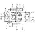
【図6】図5に示されている押しボタン装置の上面図である。
【図7】図6のVII−VII線に沿った断面図である。
【符号の説明】
1 ベースストリップ、 2 回動ストリップ、 3 ヒンジ、
4、5 トング、 6 フォーク、 7、8 ブランチ、
9、10 ブランチ端部[0001]
BACKGROUND OF THE INVENTION
The present invention allows the at least one pivot strip to be folded over the base strip, the strips are attached to each other by a hinge at each end and a snapping device is provided on these strips in the closed position. The present invention relates to a fastener having a foldable buckle that can lock them together.
[0002]
[Prior art]
Fasteners that meet the above definition have been proposed several times.
Swiss Patent No. 663,522 comprises a base strip provided with an elongated opening so that a rotating strip provided with two elongated horns extending in the direction of the opening of the base strip can be folded onto the base strip. A fastener with a foldable buckle is disclosed. When the clasp is in the closed position, the two horns of the pivot strip are forcibly engaged within the opening of the base strip to form a snap fastening device with this system. Since the opening and the horn are oriented in the longitudinal direction of the fastener, the movement to try to fold the fastener in the longitudinal direction will not cause the fastener to open accidentally, but the horn and opening are perpendicular to the strip direction. There is a risk that such a false opening will occur if it faces in any direction.
[0003]
Similar devices are also disclosed in Swiss Patent No. 593,648, Swiss Patent No. 353,567 and Swiss Patent No. 671,499.
The fastener disclosed in French Patent No. 2,735,335 also raises the first tongue from the base strip and the second tongue from the pivoting strip, with the two tongs pointed back to back in the closed position. A snap fastening device is provided so that the portion and the end portion are aligned. This patent contemplates the use of a second pivot strip that can be attached with a snap fastener as described above or with a push button using the same base strip. For this reason, the base strip is a multi-purpose type in that it can be mounted either with a rotating strip with a tongue or a rotating strip with a manually operated push button.
[0004]
[Problems to be solved by the invention]
All of these systems suffer from the fact that they wear quickly and the fastener cannot be properly secured with a relatively small number of opening and closing operations. This is essentially due to the very short horn protrusion length, which results in very small bends and thus high snap fit, resulting in rapid system wear. .
The present invention seeks to solve such problems of conventional fasteners.
[0005]
[Means for Solving the Problems]
The fastener of the present invention includes a snap fastening device including two tongues raised from a base strip so as to face each other in a direction perpendicular to the longitudinal direction of the fastener, and a tuning fork-shaped fork formed on the rotating strip. The fork has two branches with bent ends extending in the longitudinal direction of the fastener, each of the ends being from the base strip when the fastener is in the closed position. It is configured to be snap-locked to one of the raised tongs.
The present invention will now be further described with reference to the accompanying drawings.
[0006]
DETAILED DESCRIPTION OF THE INVENTION
This embodiment is a bracelet clasp. As shown in FIG. 1, the bracelet clasp is foldable. In this fastener, at least one
[0007]
As shown in FIG. 1, the fastener can include a
[0008]
The fastener may only be provided with a single
[0009]
The subject of the present invention, namely a snap-on device or a snap-lock device, will now be described.
As shown in FIG. 1, two
[0010]
According to the particular embodiment of the invention shown in the drawing, flared
[0011]
The snap fastener is shown in particular detail in FIG. 3, which is a cross-section along the line III-III in FIG. FIG. 3 shows the
[0012]
As shown in the drawings, the
[0013]
The
FIGS. 1 and 2 show that the snap device of the present invention is provided on the first and second strips when the fastener includes two rotating strips.
[0014]
However, it is also conceivable to provide a push-button locking device on one of the rotating strips and a snap-on device according to the invention on the other strip. This case is shown in FIGS. In these drawings, the
Accordingly, FIGS. 4 to 7 show that the
This device is shown in perspective in FIGS. 4 and 5, but will be described in more detail with reference to the plane of FIG. 6 and the cross section of FIG.
[0015]
The
[0016]
4 and 5, the first bracelet part is attached to the
[0017]
It can be seen that by very simple means (removing and replacing one bar) the fasteners locked with snap fasteners can be replaced with fasteners locked with push buttons. In either case, it is possible to improve the safety of the closed state of the fastener while using the same base strip.
[Brief description of the drawings]
FIG. 1 is a perspective view of a fastener of the present invention in an open position.
FIG. 2 is a perspective view of the fastener of the present invention in the closed position.
3 is a cross-sectional view taken along line III-III in FIG.
FIG. 4 is a perspective view of the fastener of the present invention in an open position, the pivot strip of the fastener being provided with a push button locking device.
FIG. 5 is a perspective view of the fastener of FIG. 4 in a closed position.
6 is a top view of the push button device shown in FIG. 5. FIG.
7 is a cross-sectional view taken along line VII-VII in FIG.
[Explanation of symbols]
1 base strip, 2 rotating strip, 3 hinge,
4, 5 tongs, 6 forks, 7, 8 branches,
9, 10 Branch end
Claims (3)
前記スナップ留め装置は、
互いに対向するよう前記ベースストリップ(1)から隆起されるとともにそれらのそれぞれに第1係合構造としてのエッジ(20、21)が形成された第1、第2のトング(4、5)と、前記第1の回動ストリップ(2)に形成された音叉形のフォーク(6)とを備えており、
このフォーク(6)は、そのそれぞれの端部(9、10)に第2係合構造としての傾斜平面(13、14)が設けられた第1、第2のブランチ(7、8)を有しており、さらに、これらの第1、第2のブランチ(7、8)は、前記第1の回動ストリップ(2)と前記ベースストリップ(1)とが閉鎖位置にある時に、前記対向する第1、第2のトング(4、5)の間に挿入されて、前記第1のブランチ(7)の端部(9)に形成された傾斜平面(13)が前記第1のトング(4)のエッジ(20)に、前記第2のブランチ(8)の端部(10)に形成された傾斜平面(14)が前記第2のトング(5)のエッジ(21)にそれぞれ係合して前記ベースストリップ(1)と前記第1の回動ストリップ(2)とが互いにスナップロックされることを特徴とする留め金具。The base strip (1) and the first pivot strip (2) are hinged at each end (3) so that the first pivot strip (2) can be folded over the base strip (1). ) And foldable buckles provided with snap-on devices on these strips so that the base strip (1) and the first pivoting strip (2) can be locked together in the closed position. A fastener,
The snap-on device is
First, a second tongue (4, 5) the edges of the first engagement structure (20, 21) is formed in each is Rutotomoni thereof raised from the base strip (1) so as to be opposed to each other, A tuning fork-shaped fork (6) formed on the first rotating strip ( 2 ),
The fork (6) is closed the first respectively of the end portions (9, 10) inclined planes as the second engaging structure (13, 14) is provided, the second branch of the (7,8) Furthermore, these first and second branches (7, 8) are opposed to each other when the first pivot strip (2) and the base strip (1) are in the closed position. An inclined plane (13) inserted between the first and second tongs (4, 5) and formed at the end (9) of the first branch (7) is the first tong (4 ) And the inclined plane (14) formed at the end (10) of the second branch (8) engages with the edge (21) of the second tongue (5), respectively. the base strip (1) and said first pivot strip (2) and that are snap-lock each other Te Fasteners, characterized.
Applications Claiming Priority (4)
| Application Number | Priority Date | Filing Date | Title |
|---|---|---|---|
| FR9613529 | 1996-11-06 | ||
| FR9613527 | 1996-11-06 | ||
| FR9613529 | 1996-11-06 | ||
| FR9613527 | 1996-11-06 |
Publications (2)
| Publication Number | Publication Date |
|---|---|
| JPH10146208A JPH10146208A (en) | 1998-06-02 |
| JP4037495B2 true JP4037495B2 (en) | 2008-01-23 |
Family
ID=26233087
Family Applications (1)
| Application Number | Title | Priority Date | Filing Date |
|---|---|---|---|
| JP30403297A Expired - Fee Related JP4037495B2 (en) | 1996-11-06 | 1997-11-06 | Folding buckle clasp |
Country Status (8)
| Country | Link |
|---|---|
| US (1) | US5857243A (en) |
| EP (1) | EP0843977B1 (en) |
| JP (1) | JP4037495B2 (en) |
| CN (1) | CN1145428C (en) |
| DE (1) | DE69713713T2 (en) |
| HK (1) | HK1013592A1 (en) |
| SG (1) | SG63765A1 (en) |
| TW (1) | TW564699U (en) |
Families Citing this family (15)
| Publication number | Priority date | Publication date | Assignee | Title |
|---|---|---|---|---|
| EP0833579B1 (en) * | 1995-04-04 | 2002-08-14 | Montres Rolex Sa | Watchstrap clasp |
| CH691160A5 (en) * | 1996-08-27 | 2001-05-15 | Rolex Montres | Folding clasp. |
| US6442743B1 (en) | 1998-06-12 | 2002-08-27 | Monterey Design Systems | Placement method for integrated circuit design using topo-clustering |
| US6434798B1 (en) * | 1998-07-02 | 2002-08-20 | Citizen Watch Co., Ltd. | Rotation stopper for opening and closing plates in center fixing device of band-shaped ornament |
| CN2358729Y (en) * | 1999-01-04 | 2000-01-19 | 加宏企业有限公司 | Watchband buckle pack of metal watchband |
| JP2003275005A (en) * | 2002-03-26 | 2003-09-30 | Seiko Instruments Inc | Arm-mounted portable apparatus |
| FR2842081B1 (en) * | 2002-07-11 | 2004-08-27 | Chatelain Sa G & F | AUTOMATIC CLASP FOR A WATCH STRAP |
| EP1491973A1 (en) * | 2003-06-25 | 2004-12-29 | The Swatch Group Management Services AG | Clasp bracelet having electrical connection means |
| US8789246B2 (en) * | 2011-06-10 | 2014-07-29 | Suunto Oy | Asymmetric butterfly clasp |
| EP2644050B1 (en) * | 2012-03-27 | 2016-05-25 | Rolex S.A. | Opening clasp for bracelet |
| EP2870893B1 (en) * | 2013-11-07 | 2016-06-08 | The Swatch Group Management Services AG | Bracelet clasp |
| JP6749540B2 (en) * | 2014-09-19 | 2020-09-02 | アダマンド並木精密宝石株式会社 | Buckle, wristwatch, and method for manufacturing buckle or wristwatch |
| CN105105430A (en) * | 2015-08-07 | 2015-12-02 | 惠州Tcl移动通信有限公司 | Wearable equipment and fastening assembly thereof |
| CH713613B1 (en) * | 2017-03-23 | 2021-03-15 | Bulgari Horlogerie Sa | Folding clasp |
| DE102018006948B4 (en) * | 2018-09-03 | 2022-04-21 | Martin Schmidhofer | COUPLING DEVICE AND FOLDING CLASP |
Family Cites Families (15)
| Publication number | Priority date | Publication date | Assignee | Title |
|---|---|---|---|---|
| FR353567A (en) * | 1905-04-20 | 1905-09-14 | James Holms Junior | Advanced spreader bar for chains and tow bars |
| FR593648A (en) * | 1925-02-07 | 1925-08-28 | Process for the simultaneous production, by synthesis, of methyl alcohol and liquid hydrocarbons | |
| GB314415A (en) * | 1928-03-26 | 1929-06-26 | Ralph Sadleir Falkiner | Improvements in and relating to cane harvesting machinery |
| FR663522A (en) * | 1928-10-31 | 1929-08-22 | Fixed or swivel clamp vice with special device, in horizontal or vertical position | |
| US1741421A (en) * | 1929-01-16 | 1929-12-31 | Louis Stern Company | Foldable extension device |
| US1809278A (en) * | 1929-12-20 | 1931-06-09 | Kestenman Bros Mfg Co | Clasping device for wrist watch straps, bracelets and the like |
| US2532840A (en) * | 1948-02-03 | 1950-12-05 | Kreisler Mfg Corp Jacques | Folding extension device |
| FR2184440B1 (en) * | 1972-05-17 | 1976-01-16 | Cartier Fr | |
| FR2442605A1 (en) * | 1978-11-29 | 1980-06-27 | Miserez Francis | Fastener for watch bracelet - has two arms articulated on plate and locking on to it |
| CA1158844A (en) * | 1980-05-13 | 1983-12-20 | Yoshimi Takimoto | Buckles |
| CH665101A5 (en) * | 1986-03-20 | 1988-04-29 | G Et F Chatelain S A | Ultra-flat folding fastener for bracelet - is operated by buttons in recessed piece hinged to short part with engaging opening in long part |
| CH667979A5 (en) * | 1986-10-08 | 1988-11-30 | Georges Claude | Adjustable fastener for bracelet - has curved central plate having groove in which arm of one part slides and locks in notches in groove |
| FR2615368B1 (en) * | 1987-05-18 | 1989-07-13 | Boucledor Sa | DEPLOYMENT BUCKLE CLASP |
| FR2634107B1 (en) * | 1988-07-15 | 1990-11-02 | Omega Sa | FENDER ADJUSTABLE BRACELET CLASP |
| FR2735335B1 (en) * | 1995-06-15 | 1997-08-01 | Smh Management Services Ag | FASTENER BUCKLE CLASP |
-
1997
- 1997-10-20 TW TW091212024U patent/TW564699U/en unknown
- 1997-10-21 US US08/955,364 patent/US5857243A/en not_active Expired - Lifetime
- 1997-10-22 SG SG1997003843A patent/SG63765A1/en unknown
- 1997-10-31 DE DE69713713T patent/DE69713713T2/en not_active Expired - Lifetime
- 1997-10-31 EP EP97119059A patent/EP0843977B1/en not_active Expired - Lifetime
- 1997-11-05 CN CNB971141347A patent/CN1145428C/en not_active Expired - Fee Related
- 1997-11-06 JP JP30403297A patent/JP4037495B2/en not_active Expired - Fee Related
-
1998
- 1998-12-23 HK HK98115064A patent/HK1013592A1/en not_active IP Right Cessation
Also Published As
| Publication number | Publication date |
|---|---|
| EP0843977B1 (en) | 2002-07-03 |
| DE69713713D1 (en) | 2002-08-08 |
| EP0843977A1 (en) | 1998-05-27 |
| SG63765A1 (en) | 1999-03-30 |
| CN1145428C (en) | 2004-04-14 |
| HK1013592A1 (en) | 1999-09-03 |
| TW564699U (en) | 2003-12-01 |
| CN1185302A (en) | 1998-06-24 |
| US5857243A (en) | 1999-01-12 |
| DE69713713T2 (en) | 2003-02-20 |
| JPH10146208A (en) | 1998-06-02 |
Similar Documents
| Publication | Publication Date | Title |
|---|---|---|
| JP4037495B2 (en) | Folding buckle clasp | |
| EP0587319B1 (en) | Buckle for watch bands | |
| US4343501A (en) | Door handle assembly | |
| JP2720174B2 (en) | buckle | |
| JPS61168302A (en) | Middle metal clasp of clock band | |
| US5689859A (en) | Bracelet clasp with unfolding buckle | |
| JP3920391B2 (en) | Extendable clasp for bangles | |
| JP2001252108A (en) | Buckle assembly having high safety | |
| JPH06124U (en) | Inner clasp of watch band | |
| US5870803A (en) | Double-locking clasp for watch band | |
| JPS583527Y2 (en) | Slider with automatic stop device for slide fasteners | |
| KR960010613B1 (en) | Hair-holding accessories | |
| JPS5922504A (en) | Clamp for safety belt | |
| JP4838457B2 (en) | Watch band fastener | |
| JPS6228883Y2 (en) | ||
| US5016410A (en) | Device for the localized fastening of elements having an edge, especially of plates to a supporting structure | |
| US3465393A (en) | Seat belt buckle | |
| US1907778A (en) | Separable fastener | |
| JPH0121203Y2 (en) | ||
| JPH0421451Y2 (en) | ||
| CN1214222A (en) | Hinge fastener | |
| KR910005457Y1 (en) | Buckle | |
| JPH0610820Y2 (en) | Nakadome clasp for watch band | |
| JPS6239695Y2 (en) | ||
| JP2606529Y2 (en) | Binder with locking device |
Legal Events
| Date | Code | Title | Description |
|---|---|---|---|
| A521 | Written amendment |
Free format text: JAPANESE INTERMEDIATE CODE: A523 Effective date: 20040813 |
|
| A621 | Written request for application examination |
Free format text: JAPANESE INTERMEDIATE CODE: A621 Effective date: 20040813 |
|
| A131 | Notification of reasons for refusal |
Free format text: JAPANESE INTERMEDIATE CODE: A131 Effective date: 20070123 |
|
| A521 | Written amendment |
Free format text: JAPANESE INTERMEDIATE CODE: A523 Effective date: 20070402 |
|
| A131 | Notification of reasons for refusal |
Free format text: JAPANESE INTERMEDIATE CODE: A131 Effective date: 20070605 |
|
| A521 | Written amendment |
Free format text: JAPANESE INTERMEDIATE CODE: A523 Effective date: 20070904 |
|
| TRDD | Decision of grant or rejection written | ||
| A01 | Written decision to grant a patent or to grant a registration (utility model) |
Free format text: JAPANESE INTERMEDIATE CODE: A01 Effective date: 20071002 |
|
| A61 | First payment of annual fees (during grant procedure) |
Free format text: JAPANESE INTERMEDIATE CODE: A61 Effective date: 20071101 |
|
| R150 | Certificate of patent or registration of utility model |
Free format text: JAPANESE INTERMEDIATE CODE: R150 |
|
| FPAY | Renewal fee payment (event date is renewal date of database) |
Free format text: PAYMENT UNTIL: 20101109 Year of fee payment: 3 |
|
| FPAY | Renewal fee payment (event date is renewal date of database) |
Free format text: PAYMENT UNTIL: 20101109 Year of fee payment: 3 |
|
| FPAY | Renewal fee payment (event date is renewal date of database) |
Free format text: PAYMENT UNTIL: 20111109 Year of fee payment: 4 |
|
| FPAY | Renewal fee payment (event date is renewal date of database) |
Free format text: PAYMENT UNTIL: 20111109 Year of fee payment: 4 |
|
| FPAY | Renewal fee payment (event date is renewal date of database) |
Free format text: PAYMENT UNTIL: 20121109 Year of fee payment: 5 |
|
| FPAY | Renewal fee payment (event date is renewal date of database) |
Free format text: PAYMENT UNTIL: 20121109 Year of fee payment: 5 |
|
| FPAY | Renewal fee payment (event date is renewal date of database) |
Free format text: PAYMENT UNTIL: 20131109 Year of fee payment: 6 |
|
| R250 | Receipt of annual fees |
Free format text: JAPANESE INTERMEDIATE CODE: R250 |
|
| LAPS | Cancellation because of no payment of annual fees |