JP4838457B2 - Watch band fastener - Google Patents
Watch band fastener Download PDFInfo
- Publication number
- JP4838457B2 JP4838457B2 JP2001257397A JP2001257397A JP4838457B2 JP 4838457 B2 JP4838457 B2 JP 4838457B2 JP 2001257397 A JP2001257397 A JP 2001257397A JP 2001257397 A JP2001257397 A JP 2001257397A JP 4838457 B2 JP4838457 B2 JP 4838457B2
- Authority
- JP
- Japan
- Prior art keywords
- female
- male
- connecting portion
- fastener according
- tongue
- Prior art date
- Legal status (The legal status is an assumption and is not a legal conclusion. Google has not performed a legal analysis and makes no representation as to the accuracy of the status listed.)
- Expired - Fee Related
Links
- 230000008878 coupling Effects 0.000 claims description 40
- 238000010168 coupling process Methods 0.000 claims description 40
- 238000005859 coupling reaction Methods 0.000 claims description 40
- 210000002105 tongue Anatomy 0.000 claims description 32
- 239000000919 ceramic Substances 0.000 claims description 2
- 239000000463 material Substances 0.000 claims description 2
- 239000002184 metal Substances 0.000 claims description 2
- 229910052751 metal Inorganic materials 0.000 claims description 2
- 229920003023 plastic Polymers 0.000 claims description 2
- 239000004033 plastic Substances 0.000 claims description 2
- 230000005489 elastic deformation Effects 0.000 claims 1
- 238000004519 manufacturing process Methods 0.000 description 10
- 238000000926 separation method Methods 0.000 description 3
- 238000002347 injection Methods 0.000 description 1
- 239000007924 injection Substances 0.000 description 1
- 238000003780 insertion Methods 0.000 description 1
- 230000037431 insertion Effects 0.000 description 1
- 150000002739 metals Chemical class 0.000 description 1
- 238000012986 modification Methods 0.000 description 1
- 230000004048 modification Effects 0.000 description 1
- 210000000707 wrist Anatomy 0.000 description 1
Images


Classifications
-
- A—HUMAN NECESSITIES
- A44—HABERDASHERY; JEWELLERY
- A44C—PERSONAL ADORNMENTS, e.g. JEWELLERY; COINS
- A44C5/00—Bracelets; Wrist-watch straps; Fastenings for bracelets or wrist-watch straps
- A44C5/18—Fasteners for straps, chains or the like
- A44C5/20—Fasteners for straps, chains or the like for open straps, chains or the like
- A44C5/2066—Fasteners with locking means acting parallel to the main plane of the fastener and perpendicularly to the direction of the fastening
-
- Y—GENERAL TAGGING OF NEW TECHNOLOGICAL DEVELOPMENTS; GENERAL TAGGING OF CROSS-SECTIONAL TECHNOLOGIES SPANNING OVER SEVERAL SECTIONS OF THE IPC; TECHNICAL SUBJECTS COVERED BY FORMER USPC CROSS-REFERENCE ART COLLECTIONS [XRACs] AND DIGESTS
- Y10—TECHNICAL SUBJECTS COVERED BY FORMER USPC
- Y10T—TECHNICAL SUBJECTS COVERED BY FORMER US CLASSIFICATION
- Y10T24/00—Buckles, buttons, clasps, etc.
- Y10T24/45—Separable-fastener or required component thereof [e.g., projection and cavity to complete interlock]
- Y10T24/45225—Separable-fastener or required component thereof [e.g., projection and cavity to complete interlock] including member having distinct formations and mating member selectively interlocking therewith
- Y10T24/45471—Projection having movable connection between components thereof or variable configuration
- Y10T24/45524—Projection having movable connection between components thereof or variable configuration including resiliently biased projection component or surface segment
- Y10T24/45529—Requiring manual force applied against bias to interlock or disengage
-
- Y—GENERAL TAGGING OF NEW TECHNOLOGICAL DEVELOPMENTS; GENERAL TAGGING OF CROSS-SECTIONAL TECHNOLOGIES SPANNING OVER SEVERAL SECTIONS OF THE IPC; TECHNICAL SUBJECTS COVERED BY FORMER USPC CROSS-REFERENCE ART COLLECTIONS [XRACs] AND DIGESTS
- Y10—TECHNICAL SUBJECTS COVERED BY FORMER USPC
- Y10T—TECHNICAL SUBJECTS COVERED BY FORMER US CLASSIFICATION
- Y10T24/00—Buckles, buttons, clasps, etc.
- Y10T24/45—Separable-fastener or required component thereof [e.g., projection and cavity to complete interlock]
- Y10T24/45225—Separable-fastener or required component thereof [e.g., projection and cavity to complete interlock] including member having distinct formations and mating member selectively interlocking therewith
- Y10T24/45471—Projection having movable connection between components thereof or variable configuration
- Y10T24/45524—Projection having movable connection between components thereof or variable configuration including resiliently biased projection component or surface segment
- Y10T24/45545—Projection having movable connection between components thereof or variable configuration including resiliently biased projection component or surface segment forming total external surface of projection
- Y10T24/45581—Projection having movable connection between components thereof or variable configuration including resiliently biased projection component or surface segment forming total external surface of projection having inserted end formed by oppositely biased surface segments
-
- Y—GENERAL TAGGING OF NEW TECHNOLOGICAL DEVELOPMENTS; GENERAL TAGGING OF CROSS-SECTIONAL TECHNOLOGIES SPANNING OVER SEVERAL SECTIONS OF THE IPC; TECHNICAL SUBJECTS COVERED BY FORMER USPC CROSS-REFERENCE ART COLLECTIONS [XRACs] AND DIGESTS
- Y10—TECHNICAL SUBJECTS COVERED BY FORMER USPC
- Y10T—TECHNICAL SUBJECTS COVERED BY FORMER US CLASSIFICATION
- Y10T24/00—Buckles, buttons, clasps, etc.
- Y10T24/47—Strap-end-attaching devices
- Y10T24/4745—End clasp
-
- Y—GENERAL TAGGING OF NEW TECHNOLOGICAL DEVELOPMENTS; GENERAL TAGGING OF CROSS-SECTIONAL TECHNOLOGIES SPANNING OVER SEVERAL SECTIONS OF THE IPC; TECHNICAL SUBJECTS COVERED BY FORMER USPC CROSS-REFERENCE ART COLLECTIONS [XRACs] AND DIGESTS
- Y10—TECHNICAL SUBJECTS COVERED BY FORMER USPC
- Y10T—TECHNICAL SUBJECTS COVERED BY FORMER US CLASSIFICATION
- Y10T24/00—Buckles, buttons, clasps, etc.
- Y10T24/47—Strap-end-attaching devices
- Y10T24/4782—Watch strap
Landscapes
- Buckles (AREA)
Description
【0001】
【発明の属する技術分野】
本発明は時計バンドの第1及び第2要素を連結させる形式の留め具に関する。
【0002】
【従来の技術】
時計バンド用の留め具はいくつかの基準に添う必要がある。これらの基準は特に使いやすさ、操作の安全性、及び安価に製造することに関する。
【0003】
このタイプに関する留め具は多く知られている。それらのいくつかは上記引用した条件によく応じている。しかしいくつかの問題点も有している。それらのいくつかは例えば、製造するのに高くつくとか、同時に他方では、製造するのが簡単であるものは取扱いが難しいとかである。この点で多くの公知の留め具は特に取扱いが難しい。それは留め具の2つの部品を着脱するために1つの部品を他の部品に対してピボット回転させなければならないためである。
【0004】
更に多くの公知の留め具は特に複数の製造工程で特別な製造作業を必要とする形状を有している。あるいはいくつかの部品は高価な射出成形用金型が必要な形状を有しており製造コストを上げることとなる。
【0005】
これらは、特に最も簡単な例では、ピボット回転するストリップが折り重ねられる基本ストリップを備える広げるタイプの留め具である。これらのストリップはヒンジの作用によってそれらの端部の1つにより互いに取付けられ、そして常に一方が他方上へ密接した位置にパチンとはまることができる留め具装置を含んでいる。これらの広げるストリップ留め具は作るのが難しく、従って製造するのに高くつく複雑な形状を有していることに加え、しばしば使うのに不便である。更に、これらのシステムはすぐに摩滅し、比較的少ない回数の開閉動作後に所定の場所に適切に留め具をパチンとはめることができなくなるという欠点を有している。これは基本的にパチンとはめるための大きな力がかかることによるものであり、従ってシステムがすぐ摩滅する。更にユーザが気付かずに留め具のストリップの1つを引掛けて誤って留め具が開いて時計をなくす危険にさらされることがたびたび発生する。
【0006】
第1及び第2のバンドストランドを互いに連結することができる開放タイプの留め具も公知である。これらの留め具は、伝統的にストランドの1つの自由端にロッドを用いて固定するバックルと留め針を備えている。他のストランドの自由端をバックルの下を通し、ストランドに形成させた孔の1つに留め針を通して固定する。この端部は端部を保持する輪の下で摺動できる。
【0007】
バックルを有する留め具は単純で、従って製造するのが安価であるという主となる利点を有する。しかし、人が時計を手首に固定しようとする時、時計を離してしまうことがしばしばあるので、時計は落下して損傷を受ける。これらの留め具もまた魅力がなく、その結果、簡単に使用できるということを犠牲にすることなく、洗練されたデザインで操作性のよい時計を探している顧客の期待に応じられない場合が増加する。
【0008】
最後にバックルを有する留め具によって固定されるバンドは、すぐに摩滅する傾向がある。このことは特に留め針を収容する目的の孔が作られたストランドに当てはまる。実際、供給されたユーザはいつも留め針をバンドの同じ孔に挿入するのでこの孔は大きくなり裂けやすくする。同様に折り目がバックルの下を通る場所に形成され、そのような折り目もバンドを脆弱にし、裂けやすくする。
【0009】
【発明が解決しようとする課題】
本発明の目的は従って上記問題点をなくし、製造が非常に簡単で使用しやすく安全な時計用バンド留め具を作ることにある。
【0010】
【課題を解決するための手段】
本発明は従って時計バンド留め具に関し、雄連結部を雌連結部に挿入することによって連結可能である2個の雄連結部と2個の雌連結部と、雄連結部を外方へ引張ることが不可能となるように雄連結部に設けられ、雄連結部が雌連結部に係合位置に押し込まれた時、雌連結部に設けられた引掛け手段とロックする弾性ロック手段を含み、雄連結部を雌連結部へ更に押し込むことにより、雄連結部と雌連結部が互いに連結解除可能となり、故にロック手段が引掛け手段から解除されて雄連結部が雌連結部から引き出すことができることを特徴とする。
【0011】
これらの特徴の結果、本発明は使用しやすい留め具となる。実際に、留め具を固定するためには、雄連結部に設けられたロック手段が雌連結部に設けられた引掛け手段とロックする係合位置まで雄連結具を雌連結具に挿入するだけでよい。留め具を開くために、雄連結部を雌連結具に挿入する動作は継続される。ロック手段はその後引掛け手段からはずれので、雄連結部を雌連結部から引き出すだけでよい。
【0012】
本発明による留め具も高い作業信頼性を提供する。雄連結部が雌連結部へそれらの係合位置まで押し込まれると、雄連結部を雌連結部から引き出すことは不可能となる。その結果、たとえユーザが留め具の部品の1つを気付かずに引掛けても、開くことはない。留め具はユーザが雄連結部を更に雌連結部に押し込むことによって意図的に留め具を作用させた時に開放される。
【0013】
本発明の補足的な特徴によれば、ロック手段は雄連結部が雌連結部に係合する方向に対して横方向に弾性を有しており、更にロック手段は留め具の平面に対して垂直方向の平面に弾性を有している。
【0014】
雄連結部が雌連結部に挿入された時、雌連結部に設けられた引掛け手段はロック手段を弾性的に変形させ、ロック手段に張力を与えるために雄連結部のロック手段を雄連結部と雌連結部の係合方向に対して横方向に押しつける。弾性ロック手段はその後引掛け手段を急にロックし、確実な結合を確保していかなる偶発的な分離も妨げる。ユーザが留め具を開放したいと思い、雄連結部を更に雌連結部に押し込んだ時、ロック手段は留め具の平面に対して垂直方向に下方へ弾性変形し、その後ロック手段は引掛け手段を回避するために弾性力によって元の形状に戻る。したがって、雄連結部は雌連結部から簡単に離れる。
【0015】
本発明の留め具は何の設定や調整も必要なく、2つの連結部を解除するためのいかなる移動部材も含んでおらず、製造コストを十分に下げることが可能である。最後に、雄連結部と雌連結部はすぐに、しかも非常に簡単にはめ込むことができ、いかなる偶発的なの分離も妨げるようにしっかりと組付けられることができる。
【0016】
本発明の他の特徴及び利点は、以下の本発明による留め具の限定されない実施例を単に示すことを目的とした実施例の詳細な記載を添付した図面と照らし合わせて読むことにより更に明白になるであろう。
【0017】
【発明の実施の形態】
図1〜図3に示すように、全体的な参照番号1で全体を示す本発明による留め具は基本的に雄連結部2とその圧す連結部が挿入される雌連結部4とからなる。雄連結部2と雌連結部4は共にいろいろな種類のプラスチック、金属、セラミック又は弾性変形できる他の材料から作られる。
【0018】
雄連結部2は全体として矩形状をしており、時計バンド(図示せず)の一方のストランド8の側面に取り付けられる横連結バー6を含む。ロック手段は雄連結部2に設けられる。図1〜図3に示す実施形態において、これらのロック手段は連結バー6の延びている方向に沿った両端部から直角方向にかつ雄連結部2と雌連結部4の連結方向に平行に突出する2つのタング10を含む。以下に詳細に述べるように、雄連結部2が雌連結部4に導入される軸の両側に対称的に配置されるこれらのロック手段は、雄連結部2が雌連結部4の係合位置に押し入れられた時、雌連結部4に設けられた引掛け手段とロックするようになっている。
【0019】
本発明による留め具1の単純化した変形例によれば、ロック手段が1つのタング10をそなえるだけでもよいことは言うまでもない。しかし、1つだけでなく2つのロック・タング10を設けると、雄連結部2が対称性となって好ましい。このことは実際には2個の雄連結部2と雌連結部4が更に速く、簡単に一緒にはめ合い、そして雄連結部2と雌連結部4がいかなる偶発的な分離も防ぐようにしっかりと組付けられることを保証する。
【0020】
雄連結部2は更に雄連結部2を雌連結部4へ案内する手段を含む。これらの案内手段は別のタング12の形態をとり、2つのロック・タング10の間にそれらから同じ距離の所に設けられ、それらと平行に延びる、すなわち雄連結部2を雌連結部4へ挿入する方向に延びている。以下の記載を読んで分かるように、案内手段は本発明による留め具1が正確に作動するのに不可欠なものではないが、案内手段は雄連結部2を雌連結部4に導入するのを容易にする。
【0021】
最後に、雄連結部2はその自由端部に時計バンドのストランド8の1つを取り付ける手段を含む。これらの取付手段は連結バー6の2つの端部に設けられた孔16を貫通するバー14を含む。バンド部分8はバー14に取り付けられ、その後バー14は孔16に挿入される。バー14は例えば2本の回転可能軸18及び20でよく、そのうちの1つの回転可能軸18は動かず、他方の回転可能軸20は可動であり、バー14を外方向へ押すバー14の内側に収容されたバネの動きに影響を受ける。
【0022】
雌連結部4はまた全体として一般的に略矩形状をしている。雄連結部2と同様に横連結バー22を含む。外側アーム24と内側アーム26は連結バー22に直角方向に、すなわち、雄連結部2と雌連結部4の連結方向に平行に延びる。
【0023】
アーム24と26が対抗する面は2つの通路28及び30を形成し、雄連結部2が雌連結部4に挿入された時、その通路へロック・タング10が滑り込む。任意には、2つの内側アーム26の対向面も案内タング12により貫通される中央通路32を形成している。
【0024】
上記のように、雌連結部4は引掛け手段を含み、そこへ雄連結部2に設けられたロック手段が固定する。
【0025】
更に詳しくは、特に図2に示すように、これらの引掛け手段は2本の外側アーム24に作られた2つの切欠き34で形成され、そこにロック・タング10の自由端部が収容される。
【0026】
この目的のために、各ロック・タング10はその自由端にブロック36を有し、ブロック36は面38の上方へ突出して切欠き34の面内に配置される。雄連結部2が雌連結部4に案内された時、これらのブロック36が切欠き34へ挿入されて2個の雄連結部2と雌連結部4を一緒に固定させる。ブロック36の各々は平らな外側面40を有する。この平らな外側面40は対応する切欠き34と対向し、雄連結部2が雌連結部4と係合位置にある時に切欠き34の底部42に当接する。最後にブロック36はロック・タング10の自由端で終わる下方へ傾斜した面44も有する。この面44は、留め具1を開けるために雄連結部2が雌連結部4に更に押し込まれた時、切欠き34を向いている内側面46に接触する。
【0027】
なお、雄連結部2と同様に、雌連結部4は第2バンドストランド取付手段を含む。これらの取付手段は雌連結部4の自由面に設けられた1個又は数個の円柱状貫通孔48が形成され、バンド部分を固定するためにバー(図示せず)を収容するようになっている。
【0028】
一方で、図4〜図7の各々を参照し、他方で図8〜図10の各々を参照して、本発明による留め具1を形成する雄連結部2と雌連結部4の連結、連結解除作業について述べる。
【0029】
図4において、雄連結部2と雌連結部4は取り外し状態にある。図4に示す矢印は雄連結部2を雌連結部4へ連結する方向を示している。
【0030】
図5において、雄連結部2が雌連結部4に接触する。雄連結部2に備えられた案内タング12が雌連結部4に設けられた中央通路32を貫通し始める。案内タング12は本発明による留め具1が正確に作動するのに不可欠のものではないが、これらの2つの連結部2と4が互いに軸方向で正しく位置決めされて雄連結部2を雌連結部4に導入することが容易になるということを再度想起される。
【0031】
図6において、ロック・タング10は雌連結部4の通路28及び30にスライドしながら入り込み始めており、更に雌連結部4に設けられた引掛け手段の2個のスナッグ50によって内側に強制的に曲げられる。これは本発明の重要な特徴であり、ロック・タング10が雄連結部2が雌連結部4へ導入される方向に対して横方向に弾性を有するという事実により、可能となる。
【0032】
図7において、雄連結部が雌連結部の方向に導入する動きが止められている。通路28及び30が雌連結部4に設けられた引掛け手段の切欠き34に開いているので、ロック・タング10の面38の上方に突出しているブロック36は切欠き34に急に収容される。この操作の段階において、上記引用したスナッグ50がブロック36の移動を妨げるので、もはや雄連結部2を引張って雄連結部2を雌連結部4から分離することができない。なお更に、図2に明らかなように、2個のロック・タング10間の間隙D1は切欠き34の底部42を分ける間隔D2より広くされている。従ってロック・タング10はこの時弾性力を受けており、これらのタング10に設けられたブロック36は平らな外側面40を介して切欠き34の底部42に密接している。
【0033】
雄連結部2と雌連結部4の連結解除の操作について考察する。
【0034】
図8は、雄連結部2が雌連結部4に更に押し込められていることを除いて図7と同様の図であり、図中に矢印で表されている。本発明のもう一つの重要な特徴により、ロック・タング10も本発明による留め具1の平面に対して直角方向にも弾性を有する。従って雄連結部2が雌連結部4に押し込められた時、ブロック36の下方へ傾斜している面44が、接触させられると共に切欠き34に面する内側面46を越えて徐々に摺動する。ロック・タング10はその後下方へ傾斜することにより切欠き34から離され、それからロック・タング10は弾性力によりそれらの元の形状に戻る。使用者は雄連結部2を雌連結部4からはずすために図に示す矢印に沿う引張り移動力を働かせることだけ必要となる。ロック・タング10間の間隙D1は切欠き34の底部42を分ける間隔より広いので、ロック・タング10に搬送されるブロック36は、ロック・タング10がアーム24の下方外側面に沿って摺動するので、その後ブロック36は再度切欠き34に収容されることはない。
【0035】
図10において雄連結部2と雌連結部4は再度取り外し状態になる。
【0036】
なお、雄連結部2と雌連結部4は各々ケース52(図2及び図3参照)に挿入されてもよい。
【0037】
本発明は記載した実施形態に限定されず、本発明の思想から逸脱せずに当業者より予見できる改良や変形ができることは言うまでもない。
【図面の簡単な説明】
【図1】本発明による留め具を形成する雄及び雌連結部を取り外し状態で示した斜視図である。
【図2】図1の雄及び雌連結部を取り外し状態で示した平面図である。
【図3】雄及び雌連結部の図2のIII―III線に沿った断面図である。
【図4】〜【図7】雄及び雌連結部の連結作業を示す斜視図である。
【図8】〜【図10】雄及び雌連結部の連結解除作業を示す斜視図である。
【符号の説明】
1 留め具、2 雄連結部、4 雌連結部、10、12 タング、28,30,32 通路、34 切欠き、36 ブロック。[0001]
BACKGROUND OF THE INVENTION
The present invention relates to a fastener of the type that connects first and second elements of a watchband.
[0002]
[Prior art]
Watch band fasteners must meet several criteria. These standards relate particularly to ease of use, operational safety, and inexpensive manufacturing.
[0003]
Many fasteners for this type are known. Some of them respond well to the conditions cited above. However, it has some problems. Some of them are, for example, expensive to manufacture, while others are difficult to handle if they are easy to manufacture. In this respect, many known fasteners are particularly difficult to handle. This is because one part must be pivoted with respect to the other part in order to attach and detach the two parts of the fastener.
[0004]
Furthermore, many known fasteners have shapes that require special manufacturing operations, particularly in multiple manufacturing steps. Alternatively, some parts have shapes that require expensive injection molds, which increases manufacturing costs.
[0005]
These are, in the simplest example, spread-type fasteners with a basic strip on which the pivoting strip is folded. These strips are attached to each other by one of their ends by the action of a hinge and include a fastening device that can always snap into a close position on the other. These widening strip fasteners are difficult to make and are therefore inconvenient to use, in addition to having complex shapes that are expensive to manufacture. In addition, these systems have the disadvantage that they wear out quickly and cannot be properly snapped into place after a relatively small number of opening and closing operations. This is basically due to the great force applied to snap, so the system wears out quickly. In addition, it often happens that the user is in danger of catching one of the fastener strips unintentionally and accidentally opening the fastener to lose the watch.
[0006]
Also known are open-type fasteners that can connect the first and second band strands together. These fasteners have traditionally been provided with a buckle and fastening needle that is secured to one free end of the strand with a rod. The free end of the other strand is passed under the buckle and secured with a retaining needle in one of the holes formed in the strand. This end can slide under the ring holding the end.
[0007]
Fasteners with buckles are simple and thus have the main advantage of being inexpensive to manufacture. However, when a person tries to secure the watch to his wrist, the watch is often released, and the watch falls and is damaged. These fasteners are also unattractive, and as a result, they are increasingly unable to meet the expectations of customers looking for an easy-to-use watch with a sleek design without sacrificing ease of use To do.
[0008]
Bands that are finally secured by fasteners with buckles tend to wear out quickly. This is especially true for strands that have been made with holes intended to accommodate retaining needles. In fact, the supplied user always inserts the retaining needle into the same hole in the band, so that this hole becomes larger and more susceptible to tearing. Similarly, a crease is formed where it passes under the buckle, and such a crease also weakens the band and makes it easier to tear.
[0009]
[Problems to be solved by the invention]
The object of the present invention is therefore to eliminate the above-mentioned problems and to make a watch band fastener that is very simple to manufacture, easy to use and safe.
[0010]
[Means for Solving the Problems]
The present invention thus relates to a watchband fastener, with two male coupling parts and two female coupling parts that can be coupled by inserting the male coupling part into the female coupling part, and pulling the male coupling part outward. Including an elastic locking means that locks with a hooking means provided on the female connecting portion when the male connecting portion is pushed into the engaging position by the female connecting portion, By further pushing the male connecting part into the female connecting part, the male connecting part and the female connecting part can be released from each other, and therefore the locking means can be released from the hooking means and the male connecting part can be pulled out from the female connecting part. It is characterized by.
[0011]
As a result of these features, the present invention is an easy-to-use fastener. Actually, in order to fix the fastener, the male connector is simply inserted into the female connector until the locking means provided on the male connector locks with the hooking device provided on the female connector. It's okay. To open the fastener, the operation of inserting the male connector into the female connector is continued. Since the locking means is then disengaged from the hooking means, it is only necessary to pull out the male coupling part from the female coupling part.
[0012]
The fastener according to the present invention also provides high work reliability. When the male connecting portion is pushed into the female connecting portion to the engagement position, it is impossible to pull out the male connecting portion from the female connecting portion. As a result, even if the user hooks without knowing one of the fastener parts, it will not open. The fastener is released when the user intentionally activates the fastener by pushing the male connector further into the female connector.
[0013]
According to a supplementary feature of the invention, the locking means is elastic in a direction transverse to the direction in which the male coupling part engages the female coupling part, and further the locking means is against the plane of the fastener. It has elasticity in a vertical plane.
[0014]
When the male connecting part is inserted into the female connecting part, the hooking means provided on the female connecting part elastically deforms the locking means, and the locking means of the male connecting part is connected to the male to give tension to the locking means. It presses in the horizontal direction with respect to the engagement direction of a part and a female connection part. The elastic locking means then suddenly locks the hooking means, ensuring a secure connection and preventing any accidental separation. When the user wants to release the fastener and pushes the male coupling part further into the female coupling part, the locking means elastically deforms downward in a direction perpendicular to the plane of the fastener, and then the locking means engages the hooking means. In order to avoid it, it returns to its original shape by elastic force. Therefore, the male connecting portion is easily separated from the female connecting portion.
[0015]
The fastener of the present invention does not require any setting or adjustment, does not include any moving member for releasing the two connecting portions, and can sufficiently reduce the manufacturing cost. Finally, the male and female connections can be fitted very quickly and very easily and can be firmly assembled to prevent any accidental separation.
[0016]
Other features and advantages of the present invention will become more apparent from the following detailed description of the embodiments, which are intended merely to illustrate non-limiting embodiments of fasteners according to the present invention, in light of the accompanying drawings. It will be.
[0017]
DETAILED DESCRIPTION OF THE INVENTION
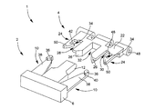
As shown in FIGS. 1 to 3, the fastener according to the present invention, which is generally indicated by the overall reference number 1, basically comprises a
[0018]
The
[0019]
It goes without saying that according to a simplified variant of the fastener 1 according to the invention, the locking means may comprise only one
[0020]
The
[0021]
Finally, the
[0022]
The
[0023]
The opposing surfaces of the
[0024]
As described above, the
[0025]
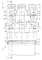
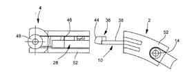
More particularly, as shown in particular in FIG. 2, these hooking means are formed by two
[0026]
For this purpose, each locking
[0027]
Similar to the
[0028]
On the other hand, referring to each of FIGS. 4 to 7, and referring to each of FIGS. 8 to 10, the connection and connection of the
[0029]
In FIG. 4, the
[0030]
In FIG. 5, the
[0031]
In FIG. 6, the
[0032]
In FIG. 7, the movement of the male connecting portion introduced in the direction of the female connecting portion is stopped. Since the
[0033]
The operation of releasing the connection between the
[0034]
FIG. 8 is a view similar to FIG. 7 except that the
[0035]
In FIG. 10, the
[0036]
In addition, the
[0037]
It goes without saying that the present invention is not limited to the described embodiments, and that modifications and variations that can be foreseen by those skilled in the art can be made without departing from the spirit of the present invention.
[Brief description of the drawings]
FIG. 1 is a perspective view showing a male and female coupling part forming a fastener according to the present invention in a removed state.
FIG. 2 is a plan view showing the male and female coupling portions of FIG. 1 in a removed state.
3 is a cross-sectional view taken along line III-III in FIG. 2 of the male and female coupling portions.
FIG. 4 is a perspective view showing a connecting operation of a male and a female connecting portion.
FIG. 8 is a perspective view showing a connection release operation of the male and female connecting portions.
[Explanation of symbols]
1 Fastener, 2 Male connection part, 4 Female connection part, 10, 12 tongue, 28, 30, 32 passage, 34 notch, 36 blocks.
Claims (15)
前記ロック手段は、雄連結部(2)を雌連結部(4)へ係合する方向に対して横方向に弾性を有し、更に前記引掛け手段に対して垂直な方向に弾性を有することを特徴とする留め具。The male connecting part (2), the female connecting part (4), and the male connecting part (2) that can be connected by inserting the male connecting part (2) into the female connecting part (4) can be pulled outward. It is provided in the male connecting part (2) so as to be impossible, and includes a hooking means provided in the female connecting part (4) and an elastic locking means for locking, and the male connecting part (2) is connected to the female connecting part ( 4) When the male connecting portion (2) is pushed into the engaging position, the male connecting portion (2) and the female connecting portion (4) can be released from each other by further pushing the male connecting portion (2) into the female connecting portion (4). Therefore , the fastener for the watch band in which the locking means is released from the hooking means and the male coupling part (2) can be pulled out from the female coupling part (4) ,
The locking means has elasticity in a lateral direction with respect to a direction in which the male connecting portion (2) is engaged with the female connecting portion (4), and further has elasticity in a direction perpendicular to the hooking means . Fastening characterized by.
Applications Claiming Priority (2)
| Application Number | Priority Date | Filing Date | Title |
|---|---|---|---|
| CH1696/00 | 2000-08-31 | ||
| CH16962000 | 2000-08-31 |
Publications (2)
| Publication Number | Publication Date |
|---|---|
| JP2002085118A JP2002085118A (en) | 2002-03-26 |
| JP4838457B2 true JP4838457B2 (en) | 2011-12-14 |
Family
ID=4565942
Family Applications (1)
| Application Number | Title | Priority Date | Filing Date |
|---|---|---|---|
| JP2001257397A Expired - Fee Related JP4838457B2 (en) | 2000-08-31 | 2001-08-28 | Watch band fastener |
Country Status (4)
| Country | Link |
|---|---|
| US (1) | US6530133B2 (en) |
| JP (1) | JP4838457B2 (en) |
| CN (1) | CN1198529C (en) |
| SG (1) | SG88832A1 (en) |
Families Citing this family (15)
| Publication number | Priority date | Publication date | Assignee | Title |
|---|---|---|---|---|
| US7178843B2 (en) * | 2002-10-23 | 2007-02-20 | Four Paws Products, Ltd. | Litter and refuse retrieval device |
| US20080250652A1 (en) * | 2007-04-10 | 2008-10-16 | Great American Tool Co. | Self locking knife and sheath |
| US20080265592A1 (en) * | 2007-04-25 | 2008-10-30 | Four Paws Products, Ltd. | Animal waste collection device with integrated bag dispenser |
| US20120013466A1 (en) * | 2010-07-19 | 2012-01-19 | Boomslang Instruments Ab | Lock mechanism for an alarm security device |
| CN103043186A (en) * | 2012-12-24 | 2013-04-17 | 苏州益童游乐设备有限公司 | Splicable bumper boat |
| US20160053478A1 (en) * | 2014-08-19 | 2016-02-25 | Charles Porter | Interlocking Clip System |
| US20180023759A1 (en) * | 2016-03-30 | 2018-01-25 | 3 T Assets, LLC | Assembly Including a Mounting Portion and an Implement-Retaining Portion |
| CN106539207B (en) * | 2016-12-08 | 2018-07-31 | 歌尔科技有限公司 | A kind of connecting structure of watchband of wearable device |
| US9962604B1 (en) * | 2016-12-16 | 2018-05-08 | Indian Industries, Inc. | Game table |
| CN107861362A (en) * | 2017-11-17 | 2018-03-30 | 郑州爱派科技有限公司 | A kind of portable intelligent watch |
| CN109363306B (en) * | 2018-12-24 | 2024-04-19 | 歌尔科技有限公司 | Wearable equipment and removable wrist strap structure thereof |
| EP4082379B1 (en) * | 2021-04-26 | 2024-05-29 | The Swatch Group Research and Development Ltd | Bracelet clasp |
| USD1074505S1 (en) * | 2022-05-17 | 2025-05-13 | Gerry Chen | Tangle-free finding |
| US12207711B2 (en) | 2022-10-20 | 2025-01-28 | Nathan Melton | Clasp |
| USD1068551S1 (en) | 2022-10-20 | 2025-04-01 | Nathan Melton | Clasp for strap or belt |
Family Cites Families (19)
| Publication number | Priority date | Publication date | Assignee | Title |
|---|---|---|---|---|
| DE2539277A1 (en) | 1975-09-04 | 1977-03-24 | Himmermann Kg Fritz | Two piece fastener for clothing - has catch plate with sprung catch piece which slides into angled groove in holder plate |
| US4035877A (en) * | 1975-09-15 | 1977-07-19 | Brownson Ivan F | Buckle |
| JPS6225146Y2 (en) * | 1980-09-29 | 1987-06-27 | ||
| US4414719A (en) * | 1982-03-22 | 1983-11-15 | Timex Corporation | Wristwatch attachment with interchangeable end pieces |
| DE3509643C1 (en) | 1985-03-16 | 1986-09-18 | Bernhard 7530 Pforzheim Mohr | Buckle for jewelry chains, bracelets, belts and other clothing |
| JPS62166715A (en) * | 1986-01-14 | 1987-07-23 | 住友電気工業株式会社 | Terminal treatment method for long striatum |
| JPH0414017Y2 (en) * | 1986-05-12 | 1992-03-31 | ||
| JPH052092Y2 (en) * | 1988-06-22 | 1993-01-20 | ||
| JPH0289915A (en) * | 1988-09-27 | 1990-03-29 | Matsushita Electric Ind Co Ltd | Combustion equipment fault memory device |
| JPH03284215A (en) * | 1990-03-30 | 1991-12-13 | Tanaka Kikinzoku Kogyo Kk | Fixture for clothings |
| US5323554A (en) * | 1992-04-22 | 1994-06-28 | Macdonald Robert D | Tube identification band |
| JPH06118U (en) * | 1992-06-15 | 1994-01-11 | 吉田工業株式会社 | buckle |
| US5427562A (en) * | 1993-09-17 | 1995-06-27 | Hwang; Ying-Teh | Brassiere |
| JPH0856718A (en) * | 1994-08-23 | 1996-03-05 | Pearl Supensaa:Kk | Fixing metal fitting of personal ornament and its use method |
| US5774957A (en) * | 1996-11-06 | 1998-07-07 | Kohl; Thomas D. | Jewelry clasp |
| US5857819A (en) * | 1997-04-29 | 1999-01-12 | Macbrud Corporation | Press-fit cotter pin |
| US6154936A (en) * | 1998-12-21 | 2000-12-05 | Down East, Inc. | Two-piece quick release buckle and strap adjuster |
| US6233793B1 (en) * | 1999-08-18 | 2001-05-22 | Fildan Accessories Corporation | Two-step garment closure, epecially as a front closure for a brassiers |
| US6360404B1 (en) * | 2000-01-21 | 2002-03-26 | Mary Tenney Mudge | Break-away buckle |
-
2001
- 2001-08-21 SG SG200105100A patent/SG88832A1/en unknown
- 2001-08-28 JP JP2001257397A patent/JP4838457B2/en not_active Expired - Fee Related
- 2001-08-29 US US09/940,525 patent/US6530133B2/en not_active Expired - Lifetime
- 2001-08-31 CN CN01132506.2A patent/CN1198529C/en not_active Expired - Fee Related
Also Published As
| Publication number | Publication date |
|---|---|
| SG88832A1 (en) | 2002-05-21 |
| US6530133B2 (en) | 2003-03-11 |
| CN1198529C (en) | 2005-04-27 |
| US20020023323A1 (en) | 2002-02-28 |
| CN1340320A (en) | 2002-03-20 |
| JP2002085118A (en) | 2002-03-26 |
| HK1045084A1 (en) | 2002-11-15 |
Similar Documents
| Publication | Publication Date | Title |
|---|---|---|
| JP4838457B2 (en) | Watch band fastener | |
| US5231740A (en) | Safety clasp for jewelry | |
| CA2053605C (en) | Shell buckle | |
| EP0204250B1 (en) | Buckle | |
| US5465472A (en) | Buckle | |
| CA1253313A (en) | Buckle | |
| EP2641498B1 (en) | Buckle | |
| KR950001602Y1 (en) | Snap buckle | |
| JPH0228324B2 (en) | ||
| JPH0431684B2 (en) | ||
| KR20000076673A (en) | Modular attachment system | |
| WO1998003103A1 (en) | Garment hanger with locking information clip | |
| CA2339067A1 (en) | Safety snap buckle | |
| EP1179303A2 (en) | Push release buckle | |
| US4631787A (en) | Buckle having manually releasable interlocking male and female portions | |
| US10588383B2 (en) | Buckle | |
| US4977650A (en) | Buckle assembly | |
| US7204002B2 (en) | Buckle and baby carrier using the same | |
| KR100500214B1 (en) | Zipper towing cord fasteners | |
| US4443916A (en) | Latching devices | |
| JPH10211005A (en) | Buckle | |
| US5974639A (en) | Non-flex locking buckle | |
| EP0493787B1 (en) | Separable bottom end assembly for slide fastener | |
| JPH052093Y2 (en) | ||
| KR102036011B1 (en) | Wire type accessory fastener |
Legal Events
| Date | Code | Title | Description |
|---|---|---|---|
| A621 | Written request for application examination |
Free format text: JAPANESE INTERMEDIATE CODE: A621 Effective date: 20080813 |
|
| A977 | Report on retrieval |
Free format text: JAPANESE INTERMEDIATE CODE: A971007 Effective date: 20110426 |
|
| A131 | Notification of reasons for refusal |
Free format text: JAPANESE INTERMEDIATE CODE: A131 Effective date: 20110510 |
|
| A601 | Written request for extension of time |
Free format text: JAPANESE INTERMEDIATE CODE: A601 Effective date: 20110810 |
|
| A602 | Written permission of extension of time |
Free format text: JAPANESE INTERMEDIATE CODE: A602 Effective date: 20110815 |
|
| A521 | Request for written amendment filed |
Free format text: JAPANESE INTERMEDIATE CODE: A523 Effective date: 20110830 |
|
| TRDD | Decision of grant or rejection written | ||
| A01 | Written decision to grant a patent or to grant a registration (utility model) |
Free format text: JAPANESE INTERMEDIATE CODE: A01 Effective date: 20110927 |
|
| A01 | Written decision to grant a patent or to grant a registration (utility model) |
Free format text: JAPANESE INTERMEDIATE CODE: A01 |
|
| A61 | First payment of annual fees (during grant procedure) |
Free format text: JAPANESE INTERMEDIATE CODE: A61 Effective date: 20110930 |
|
| FPAY | Renewal fee payment (event date is renewal date of database) |
Free format text: PAYMENT UNTIL: 20141007 Year of fee payment: 3 |
|
| R150 | Certificate of patent or registration of utility model |
Free format text: JAPANESE INTERMEDIATE CODE: R150 |
|
| R250 | Receipt of annual fees |
Free format text: JAPANESE INTERMEDIATE CODE: R250 |
|
| R250 | Receipt of annual fees |
Free format text: JAPANESE INTERMEDIATE CODE: R250 |
|
| R250 | Receipt of annual fees |
Free format text: JAPANESE INTERMEDIATE CODE: R250 |
|
| R250 | Receipt of annual fees |
Free format text: JAPANESE INTERMEDIATE CODE: R250 |
|
| LAPS | Cancellation because of no payment of annual fees |