JP4036403B2 - fishing rod - Google Patents
fishing rod Download PDFInfo
- Publication number
- JP4036403B2 JP4036403B2 JP26016598A JP26016598A JP4036403B2 JP 4036403 B2 JP4036403 B2 JP 4036403B2 JP 26016598 A JP26016598 A JP 26016598A JP 26016598 A JP26016598 A JP 26016598A JP 4036403 B2 JP4036403 B2 JP 4036403B2
- Authority
- JP
- Japan
- Prior art keywords
- grip
- piece
- peripheral surface
- axial direction
- fishing rod
- Prior art date
- Legal status (The legal status is an assumption and is not a legal conclusion. Google has not performed a legal analysis and makes no representation as to the accuracy of the status listed.)
- Expired - Fee Related
Links
Images


Description
【0001】
【発明の属する技術分野】
本発明は、魚釣りに用いる釣竿に関する。
【0002】
【従来の技術】
従来の釣竿は、竿体と、竿体の竿元側に配置されリールを装着するためのリールシートと、竿体の竿元側端部にはめ込まれて固定された蓋付き円筒型部材であるグリップとを有している。このグリップは、例えば、ポリウレタン等の合成樹脂やコルク材等の素材を用いて所定の形状に加工して、竿体の所定の箇所にはめ込んで固定されている。このグリップに用いる材質は、適度な弾性を有する,滑りにくい,加工しにくい等のグリップとして好ましい特性を有するものが用いられる。そして、ユーザがグリップを把持した際に滑りにくいようにグリップの周面上に凹凸を設けたり、また、意匠性を向上させるべく様々な模様が施されている。
【0003】
【発明が解決しようとする課題】
従来の単一の材質から形成されたグリップでは、グリップの全ての部分で同様の弾性等の特性を有しており、部分的に異なった特性付けをしてグリップ感を演出し難い。グリップは部分的に大きな力が加わる場合があり、部分的にグリップ感を変化させるのが好ましい場合がある。また、単一の素材からなるグリップでは、その色彩,模様等の演出に限界がある。
【0004】
本発明の課題は、部分的に特性に変化を付けてグリップ感に優れ、さらに意匠性にも優れるグリップを有する釣竿を提供することにある。
【0007】
【課題を解決するための手段】
発明1にかかる釣竿は、魚釣りに用いる釣竿であって、竿体と、竿体の外周面に配置される円筒型のグリップ本体と、グリップ本体周面に固定されグリップ本体と異なる材質からなるグリップ片とを備えている。
また、グリップ本体は周面上に形成された複数の窪み部を有し、グリップ片は窪み部に脱着自在に取り付けられている。
また、窪み部はグリップ本体周面上に軸方向に伸びて形成され、軸方向に形成されたレール部を有し、グリップ片はレール部上を軸方向に滑動可能である。
この場合には、ユーザがグリップを把持した際にグリップ本体を把持した部分とグリップ片を把持した部分とでそれぞれ弾性等の特性が異なり、良好なグリップ感を得られる。また、グリップ片自体がグリップ上に模様を描き意匠性も向上する。
この場合には、グリップ本体の周面に設けられた窪み部に任意にグリップ片を取り付けてグリップの位置を調整する。ユーザは環境や自分の好みに応じてグリップ片を取り付けることにより、良好なグリップ感を演出できる。また、この窪み部が取り付けたグリップ片の微妙なずれを抑えるので、グリップを把持して行う釣竿の操作性が向上する。さらに、グリップ片の脱着も容易である。
この場合には、窪み部に設けられたレール部上でグリップ片を軸方向に滑動させて、グリップ片をグリップ本体に脱着する。グリップ片をレール上で滑動可能なので、グリップ片の脱着が容易である。
【0008】
発明2に係る釣竿は、発明1の釣竿であって、グリップ片はグリップ本体の外周面より径方向外方へ突出している。
【0009】
この場合には、グリップ本体より外方に突出したグリップ片がユーザの手が軸方向に滑ってしまうのを抑える。また、意匠性も向上する。
【0010】
【発明の実施の形態】
[第1実施形態]
以下、本発明の第1実施形態について図面を参照しつつ説明する。
本発明の第1実施形態を採用した釣竿は、図1に示すように、複数の竿体からなり並継形式で連結された竿体1と、竿体1の竿元側端部に設けられた竿元グリップ2と、竿元グリップ2の穂先側に設けられた前グリップ3とを有している。また、竿元グリップ2と前グリップ3との間にはリール(図示せず)を脱着自在に装着可能なリールシート4が設けられており、このリールシート4から穂先側の竿体1の周面上には所定の間隔を隔てて釣糸が挿通可能な釣糸ガイド5が複数配置されている。
【0011】
竿体1は炭素繊維やガラス繊維などの強化繊維に樹脂を含浸させたプリプレグをマンドレルに巻回し焼成して得られた先細り筒状部材である。外周面上には撥水性,耐候性の塗材が塗布されており、また、商品イメージに応じて様々な模様が施されている。
図2及び図3に示すように、竿元グリップ2は、竿体1の外周面に配置される円筒型のグリップ本体10と、グリップ本体10の周面に周方向に間隔を隔てて形成され、竿元側端面から軸方向に伸びて形成された窪み部11と、窪み部11に脱着自在に固定されたグリップ片12とを有している。
【0012】
グリップ本体10はポリウレタン樹脂からなる発泡弾性部材であり、中央に軸方向に貫通した貫通孔を有しこの貫通孔に竿体1が貫通している。グリップ本体10の穂先側にはキャップ部材13が配置されており、グリップ本体10とともに接着剤等で竿体1に固定されている。また、グリップ本体10の周面は軸方向に凹状に掘削されて窪み部11が形成されている。この窪み部11は、図3に示すように、底部が他の部分より幅広く軸方向にレール状に形成されており、この部分がレール部11aとなっている。
【0013】
グリップ片12は、イソプレン,ブタジエン等のゴム部材からなる軸方向に長い短冊状の部材である。窪み部11に合致するように形成されており、図3に示すように、レール部11aに係合するフランジ12aを有している。
このように構成された釣竿では、窪み部11のレール部11aにフランジ12aを係止させながら、グリップ片12をグリップ本体10の竿元側端部から窪み部11に軸方向に滑動させて脱着する。このグリップ本体10とグリップ片12とはそれぞれ別の素材から形成されており、ユーザが竿元グリップ2を把持した場合、グリップ本体10とグリップ片12とでそれぞれ弾性等の特性が異なるので、良好なグリップ感を得られる。また、グリップ片12は脱着自在であり、形状や弾性の異なるグリップ片12を用意してユーザの好みに応じてすれば、環境やユーザの動作に合わせたグリップ感を演出できる。このグリップ片12は窪み部11に軸方向に滑動させて脱着可能であり操作が容易である。さらに、グリップ片12が竿元グリップ2に模様を描き出すので意匠性も向上する。
【0014】
[第2実施形態]
以下、本発明の第2実施形態について図面を参照しつつ説明する。
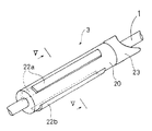
本発明の第2実施形態を採用した釣竿の前グリップ3は、図4及び図5に示すように、竿体1の外周面に配置される円筒型のグリップ本体20と、グリップ本体20の周面に周方向に間隔を隔てて軸方向に伸びて固定された複数のグリップ片22とを有している。
【0015】
グリップ本体20はポリウレタン樹脂からなる発泡弾性部材であり、中央に軸方向に貫通した貫通孔を有しこの貫通孔に竿体1が貫通している。グリップ本体20の竿元側にはキャップ部材23が配置されており、グリップ本体20とともに接着剤等で竿体1に固定されている。また、グリップ片22は、イソプレン,ブタジエン等のゴム部材からなる軸方向に長い短冊状の部材である。図5に示すように、グリップ本体20は3つのグリップ片22が配置されており、具体的には、左右1対のグリップ片22aと、グリップ片22aより周方向の幅が大きいグリップ片22bとである。これらのグリップ片22a,22bは、グリップ本体20の所定の箇所に設けられた凹状の窪み部に埋め込まれて接着剤等で固定されている。そして、グリップ片22はそれぞれグリップ本体20の外周面より径方向外方に突出して配置されている。
【0016】
このように構成された釣竿では、ユーザが前グリップ3を把持した場合、グリップ本体20とグリップ片22とでそれぞれ弾性等の特性が異なるので、良好なグリップ感を得られる。また、グリップ片22はグリップ本体20のの外周面より径方向外方に突出して配置されており、グリップを把持したユーザの手が周方向に滑ってしまうのを防止する。
【0017】
[第3実施形態]
以下、本発明の第3実施形態について図面を参照しつつ説明する。
本発明の第3実施形態を採用した釣竿の竿元グリップは、図6に示すように、竿体1の外周面に配置される円筒型のグリップ本体30と、グリップ本体30の周面に周方向に間隔を隔てて形成され、竿元側端面から軸方向に伸びて形成された窪み部31と、窪み部31に脱着自在に固定されたグリップ片32とを有している。
【0018】
グリップ本体30は、コルク材を加工したものであり、中央に軸方向に貫通した貫通孔を有しこの貫通孔に竿体1が貫通している。グリップ本体30の穂先側にはキャップ部材33が配置されており、グリップ本体30とともに接着剤等で竿体1に固定されている。また、グリップ本体30の周面は軸方向に凹状に掘削されて窪み部31が形成されている。そして、この窪み部31内には面ファスナ31aが配置されている。
【0019】
グリップ片32は、EVA等の合成樹脂からなる軸方向に長い短冊状の部材である。窪み部31に合致するように形成されており、裏側面には面ファスナ32aが貼り付けられており、窪み部31に脱着自在に固定可能になっている。
このように構成された釣竿では、必要に応じて面ファスナ31aを面ファスナ32aに貼り付けて、グリップ片32をグリップ本体30の窪み部31に固定する。ユーザが竿元グリップを把持した場合、グリップ本体30はコルク製部材でありグリップ片32はEVA等の合成樹脂であり、部分的にグリップ感に変化を付けて良好なグリップ感を得られる。
【0020】
[第4実施形態]
以下、本発明の第4実施形態について、図面を参照しつつ説明する。
本発明の第4実施形態を採用した釣竿の竿元グリップは、図7に示すように、竿体1の外周面に配置される円筒型のグリップ本体40と、グリップ本体40の周面に軸方向に間隔を隔てて形成され、グリップ本体40の周方向に配置された複数のリング状のグリップ片42とを有している。
【0021】
グリップ本体40は、EVA等の合成樹脂からなり、中央に軸方向に貫通した貫通孔を有しこの貫通孔に竿体1が貫通している。グリップ本体40の穂先側にはキャップ部材43が配置されており、グリップ本体40とともに接着剤等で竿体1に固定されている。また、グリップ片42は、ポリウレタン樹脂からなるリング状部材であって、グリップ本体40の周面上に接着剤等で固定されている。
【0022】
このように構成された釣竿では、ユーザが竿元グリップを把持した場合、グリップ本体40とグリップ片42との特性が異なるので良好なグリップ感を得られる。また、リング状のグリップ片42が竿元グリップを把持した際にユーザの手が軸方向に滑ってしまうのを抑える。また、意匠性も向上する。
[他の実施形態]
(a)グリップ本体とグリップ片との組み合わせは任意であり、例えば、同じEVA樹脂であっても、異なる弾性を有するEVA樹脂を用いてそれぞれグリップ本体とグリップ片とを形成してもよい。
(b)複数のグリップ片をグリップ本体に取り付ける際に、第1グリップ片と第2グリップ片とをそれぞれ別個の素材から形成してもよい。
【0023】
【発明の効果】
本発明にかかる釣竿のグリップは、グリップ本体に別素材からなるグリップ片が取り付けられているので、部分的に加わる力に対応できグリップ感に優れ、意匠性にも優れる。
【図面の簡単な説明】
【図1】本発明の第1実施形態を採用した釣竿の全体図。
【図2】図1の竿元グリップの拡大図。
【図3】図2のIII−III断面図。
【図4】本発明の第2実施形態を採用した釣竿の前グリップの拡大図。
【図5】図4のV−V断面図。
【図6】本発明の第3実施形態を採用した竿元グリップの拡大図。
【図7】本発明の第4実施形態を採用した竿元グリップの拡大図。
【符号の説明】
1 竿体
2 竿元グリップ
3 前グリップ
10,20,30,40 グリップ本体
11,31 窪み部
12,22,32,42 グリップ片[0001]
BACKGROUND OF THE INVENTION
The present invention relates to a fishing rod used for fishing.
[0002]
[Prior art]
A conventional fishing rod is a rod body, a reel sheet that is arranged on the rod side of the rod frame for mounting a reel, and a cylindrical member with a lid that is fitted and fixed to an end portion on the rod side of the rod body. And a grip. For example, the grip is processed into a predetermined shape using a material such as a synthetic resin such as polyurethane or a cork material, and is fitted into a predetermined portion of the housing and fixed. As the material used for the grip, a material having suitable properties as a grip having appropriate elasticity, being hard to slip and difficult to process is used. In addition, unevenness is provided on the peripheral surface of the grip so that it is difficult to slip when the user grips the grip, and various patterns are provided to improve the design.
[0003]
[Problems to be solved by the invention]
A conventional grip formed of a single material has similar characteristics such as elasticity in all parts of the grip, and it is difficult to produce a feeling of grip by giving different characteristics partially. The grip may be partially subjected to a large force, and it may be preferable to partially change the grip feeling. In addition, a grip made of a single material has a limit in the production of colors, patterns, and the like.
[0004]
An object of the present invention is to provide a fishing rod having a grip that is partly changed in characteristics, excellent in grip feeling, and excellent in design.
[0007]
[Means for Solving the Problems]
A fishing rod according to a first aspect of the present invention is a fishing rod used for fishing, and includes a rod body, a cylindrical grip body disposed on the outer peripheral surface of the rod body, and a grip made of a material different from the grip body fixed to the peripheral surface of the grip body. With a piece.
The grip body has a plurality of recesses formed on the peripheral surface, and the grip pieces are detachably attached to the recesses.
The recess is formed on the peripheral surface of the grip body so as to extend in the axial direction, has a rail portion formed in the axial direction, and the grip piece is slidable on the rail portion in the axial direction.
In this case, when the user grips the grip, characteristics such as elasticity differ between the part that grips the grip body and the part that grips the grip piece, and a good grip feeling can be obtained. In addition, the grip piece itself draws a pattern on the grip to improve the design.
In this case, a grip piece is arbitrarily attached to a recess provided on the peripheral surface of the grip body to adjust the position of the grip. The user can produce a good grip feeling by attaching grip pieces according to the environment and his / her preference. Moreover, since the subtle shift | offset | difference of the grip piece to which this hollow part was attached is suppressed, the operativity of the fishing rod performed by gripping a grip improves. Further, the grip piece can be easily attached and detached.
In this case, the grip piece is slid in the axial direction on the rail portion provided in the recess, and the grip piece is attached to and detached from the grip body. Since the grip piece can slide on the rail, the grip piece can be easily attached and detached.
[0008]
A fishing rod according to a second aspect of the present invention is the fishing rod according to the first aspect, wherein the grip piece protrudes radially outward from the outer peripheral surface of the grip body.
[0009]
In this case, the grip piece protruding outward from the grip body prevents the user's hand from sliding in the axial direction. Moreover, the designability is also improved.
[0010]
DETAILED DESCRIPTION OF THE INVENTION
[First Embodiment]
Hereinafter, a first embodiment of the present invention will be described with reference to the drawings.
As shown in FIG. 1, the fishing rod employing the first embodiment of the present invention is provided at a
[0011]
The
As shown in FIGS. 2 and 3, the
[0012]
The
[0013]
The
In the fishing rod configured as described above, the
[0014]
[Second Embodiment]
Hereinafter, a second embodiment of the present invention will be described with reference to the drawings.
As shown in FIGS. 4 and 5, the
[0015]
The
[0016]
In the fishing rod configured as described above, when the user grips the
[0017]
[Third Embodiment]
Hereinafter, a third embodiment of the present invention will be described with reference to the drawings.
As shown in FIG. 6, the rod grip of the fishing rod adopting the third embodiment of the present invention has a
[0018]
The
[0019]
The
In the fishing rod thus configured, the hook and
[0020]
[Fourth Embodiment]
Hereinafter, a fourth embodiment of the present invention will be described with reference to the drawings.
As shown in FIG. 7, the rod grip of the fishing rod employing the fourth embodiment of the present invention includes a
[0021]
The
[0022]
In the fishing rod configured as described above, when the user holds the heel grip, the
[Other Embodiments]
(A) A combination of the grip body and the grip piece is arbitrary. For example, even if the same EVA resin is used, the grip body and the grip piece may be formed using EVA resins having different elasticity.
(B) When attaching a plurality of grip pieces to the grip body, the first grip piece and the second grip piece may be formed of different materials.
[0023]
【The invention's effect】
Since the grip of the fishing rod according to the present invention has a grip piece made of a different material attached to the grip body, it can cope with a partially applied force and has an excellent grip feeling and an excellent design.
[Brief description of the drawings]
FIG. 1 is an overall view of a fishing rod adopting a first embodiment of the present invention.
FIG. 2 is an enlarged view of the collar grip of FIG.
3 is a cross-sectional view taken along line III-III in FIG.
FIG. 4 is an enlarged view of a front grip of a fishing rod adopting a second embodiment of the present invention.
5 is a VV cross-sectional view of FIG.
FIG. 6 is an enlarged view of a collar grip that employs a third embodiment of the present invention.
FIG. 7 is an enlarged view of a collar grip that employs a fourth embodiment of the present invention.
[Explanation of symbols]
DESCRIPTION OF
Claims (2)
竿体と、
前記竿体の外周面に配置され、周面上に窪み部を有する円筒型のグリップ本体と、
前記グリップ本体周面に固定され前記グリップ本体と異なる素材からなり前記窪み部に脱着自在に取付けられたグリップ片とからなり、
前記窪み部はグリップ本体周面上に軸方向に伸びて形成され、軸方向に形成されたレール部を有し、
前記グリップ片は前記レール部上を軸方向に滑動可能である
ことを特徴とする釣竿。A fishing rod used for fishing,
The body,
A cylindrical grip body disposed on the outer peripheral surface of the housing and having a recess on the peripheral surface;
Fixed to said grip body periphery consists of a gripping element mounted detachably in the grip body different from the recess Do Ri from the material,
The hollow portion is formed to extend in the axial direction on the peripheral surface of the grip body, and has a rail portion formed in the axial direction.
The grip piece is slidable on the rail portion in the axial direction.
A fishing rod characterized by that .
Priority Applications (1)
| Application Number | Priority Date | Filing Date | Title |
|---|---|---|---|
| JP26016598A JP4036403B2 (en) | 1998-09-14 | 1998-09-14 | fishing rod |
Applications Claiming Priority (1)
| Application Number | Priority Date | Filing Date | Title |
|---|---|---|---|
| JP26016598A JP4036403B2 (en) | 1998-09-14 | 1998-09-14 | fishing rod |
Publications (2)
| Publication Number | Publication Date |
|---|---|
| JP2000083526A JP2000083526A (en) | 2000-03-28 |
| JP4036403B2 true JP4036403B2 (en) | 2008-01-23 |
Family
ID=17344233
Family Applications (1)
| Application Number | Title | Priority Date | Filing Date |
|---|---|---|---|
| JP26016598A Expired - Fee Related JP4036403B2 (en) | 1998-09-14 | 1998-09-14 | fishing rod |
Country Status (1)
| Country | Link |
|---|---|
| JP (1) | JP4036403B2 (en) |
Families Citing this family (2)
| Publication number | Priority date | Publication date | Assignee | Title |
|---|---|---|---|---|
| JP4623539B2 (en) * | 2001-02-22 | 2011-02-02 | 株式会社シマノ | fishing rod |
| JP6169401B2 (en) * | 2013-04-17 | 2017-07-26 | 株式会社シマノ | Fishing rod member and fishing rod provided with the same |
-
1998
- 1998-09-14 JP JP26016598A patent/JP4036403B2/en not_active Expired - Fee Related
Also Published As
| Publication number | Publication date |
|---|---|
| JP2000083526A (en) | 2000-03-28 |
Similar Documents
| Publication | Publication Date | Title |
|---|---|---|
| JP2000060371A (en) | Grip and fishing rod provided with the same | |
| JP4036403B2 (en) | fishing rod | |
| US5123296A (en) | Break lever for a bicycle | |
| JP2003116421A (en) | Reel seat and fishing rod using the same | |
| CN216468270U (en) | Silica gel leather handle | |
| JP4282352B2 (en) | Knock part of knock type writing instrument | |
| US20030233780A1 (en) | Device to secure fishing reels to rods | |
| JP4233662B2 (en) | grip | |
| JPH1146634A (en) | Fishing rod | |
| JP2009273374A (en) | Fishing rod | |
| JPH10201876A (en) | Dumbbell | |
| JP3620025B2 (en) | Writing instrument | |
| JP4131557B2 (en) | fishing rod | |
| JP3685293B2 (en) | Reel leg fixing device for fishing rod | |
| JP4367812B2 (en) | fishing rod | |
| JP3093914U (en) | Exchangeable bag | |
| KR200304993Y1 (en) | Structure of salient to prevent of Car Handle cover slide | |
| JP3018365U (en) | Fishing reel | |
| JP3114630U (en) | Globe | |
| JP3130342U (en) | Grip structure for exercise equipment | |
| JP3130850U (en) | Gripped double crochet with cap | |
| JP2004129610A (en) | Rod | |
| JP4003897B2 (en) | fishing rod | |
| JP4094499B2 (en) | Case handle and manufacturing method thereof | |
| JPH0651054U (en) | Leather steering wheel |
Legal Events
| Date | Code | Title | Description |
|---|---|---|---|
| A521 | Written amendment |
Effective date: 20050914 Free format text: JAPANESE INTERMEDIATE CODE: A821 |
|
| A621 | Written request for application examination |
Free format text: JAPANESE INTERMEDIATE CODE: A621 Effective date: 20050914 |
|
| RD02 | Notification of acceptance of power of attorney |
Effective date: 20050914 Free format text: JAPANESE INTERMEDIATE CODE: A7422 |
|
| A977 | Report on retrieval |
Free format text: JAPANESE INTERMEDIATE CODE: A971007 Effective date: 20070606 |
|
| A131 | Notification of reasons for refusal |
Free format text: JAPANESE INTERMEDIATE CODE: A131 Effective date: 20070614 |
|
| A521 | Written amendment |
Free format text: JAPANESE INTERMEDIATE CODE: A523 Effective date: 20070802 |
|
| TRDD | Decision of grant or rejection written | ||
| A01 | Written decision to grant a patent or to grant a registration (utility model) |
Free format text: JAPANESE INTERMEDIATE CODE: A01 Effective date: 20071026 |
|
| A61 | First payment of annual fees (during grant procedure) |
Effective date: 20071029 Free format text: JAPANESE INTERMEDIATE CODE: A61 |
|
| R150 | Certificate of patent (=grant) or registration of utility model |
Free format text: JAPANESE INTERMEDIATE CODE: R150 |
|
| FPAY | Renewal fee payment (prs date is renewal date of database) |
Free format text: PAYMENT UNTIL: 20101109 Year of fee payment: 3 |
|
| FPAY | Renewal fee payment (prs date is renewal date of database) |
Free format text: PAYMENT UNTIL: 20111109 Year of fee payment: 4 |
|
| LAPS | Cancellation because of no payment of annual fees |