JP4033672B2 - Emergency notification system - Google Patents
Emergency notification system Download PDFInfo
- Publication number
- JP4033672B2 JP4033672B2 JP2001395267A JP2001395267A JP4033672B2 JP 4033672 B2 JP4033672 B2 JP 4033672B2 JP 2001395267 A JP2001395267 A JP 2001395267A JP 2001395267 A JP2001395267 A JP 2001395267A JP 4033672 B2 JP4033672 B2 JP 4033672B2
- Authority
- JP
- Japan
- Prior art keywords
- emergency
- vehicle
- emergency notification
- information
- notification device
- Prior art date
- Legal status (The legal status is an assumption and is not a legal conclusion. Google has not performed a legal analysis and makes no representation as to the accuracy of the status listed.)
- Expired - Fee Related
Links
Images


Classifications
-
- G—PHYSICS
- G08—SIGNALLING
- G08G—TRAFFIC CONTROL SYSTEMS
- G08G1/00—Traffic control systems for road vehicles
- G08G1/20—Monitoring the location of vehicles belonging to a group, e.g. fleet of vehicles, countable or determined number of vehicles
- G08G1/205—Indicating the location of the monitored vehicles as destination, e.g. accidents, stolen, rental
-
- G—PHYSICS
- G08—SIGNALLING
- G08G—TRAFFIC CONTROL SYSTEMS
- G08G1/00—Traffic control systems for road vehicles
- G08G1/16—Anti-collision systems
- G08G1/164—Centralised systems, e.g. external to vehicles
Description
【0001】
【発明の属する技術分野】
本発明は、車載用緊急事態通報装置、緊急事態連絡装置、及び、緊急事態通報システムに関し、特に、自動車等の車両において、衝突等の事故発生時に緊急事態通報を行う車載用緊急事態通報装置、緊急事態連絡装置、及び、緊急事態通報システムに関する。
【0002】
【従来の技術】
従来より、車両における走行安全性の確保のために、各種の装置が装備されるようになっている。しかし、各種装置により走行安全性が高まっても、事故発生を皆無にすることは難しい。したがって事故を含む緊急事態が発生した場合に、所定の機関に緊急事態を通報する緊急事態通報システムは有効である。
【0003】
緊急事態通報システムの例は、特開平10−162284号公報に開示されている。この公報に示されている緊急事態通報システムは、自車位置を検出し、自車位置についての情報を通信する車両局と、この車両局と双方向通信を行うと共に、この双方向通信の状態を監視するメーデーセンタ(緊急通報サービス拠点局)とを含み、車両局について緊急通報が必要になったときに、メーデーセンタは複数の緊急通報先に対し、車両局が存在する位置に基づいた優先順位で緊急通報を行う。
【0004】
また、この緊急事態通報システムは、車両事故の発生により通信設備が破壊され、通信不能になった場合でも対応できるよう、車両の走行経路中の危険度を、自車の走行状態と、走行している道路形状から検出し、危険度が所定値以上の場合には、危険度の高いエリアの進入から脱出までの時間を予測してメーデーセンタに緊急事態の事前通報を行い、予測時間経過後に通信が回復しないことで緊急事態の発生を検出することが行われる。
【0005】
【発明が解決しようとする課題】
車両事故は、自車の走行状態と走行している道路形状との関係以外に、車両同士の衝突事故等、他車両の存在を原因に発生する場合も多い。このことに対して、上述した緊急事態通報システムでは、危険度の検出に関して入力情報が不足し、危険度が低い場合にも緊急通報サービス拠点局(メーデーセンタ)に事前通報し、所定時間後にそれをキャンセルするという通信を数多くこなす必要がある。
【0006】
このため、従来の緊急事態通報システムでは、多くの場合、キャンセルされる事前通報のために、通信回線の大容量化や緊急通報サービス拠点局に設置される緊急事態連絡装置の処理能力をあらかじめ大きくしておく必要がある。
また、緊急通報サービス拠点局は、緊急事態通報装置(車両局)から送られてくるデータに基づいて運転者の自宅と通信を行い、緊急事態が物損事故や自車故障の場合には、運転者自身が健常である場合が多く、緊急事態の発生した状況を運転者自身が自宅に知らせることで充分である。
【0007】
しかし、緊急事態が人身事故や体調不良の場合は、運転者自身が病院で手当てを受ける必要があり、緊急事態通報装置(自車両)の近くに待機し続けることが困難な場合もある。仮に、緊急事態通報装置を使い、その場で自宅と連絡が取れたとしても、その後の移動先、多くは受け入れ病院の情報は不明である。
【0008】
緊急事態発生時の関係者への通報先に自宅が記載されているのは、運転者が、緊急事態において自宅待機者の助けを求めているものである。また、通報を受けた自宅待機者の関心事は、運転者の緊急事態の有無のみならず、運転者の安否や移動先をいち早く知ることにあるが、従来の緊急事態通報システムでは、これらの要求に充分対処できない。
【0009】
本発明は、上述の如き問題点を解消するためになされたもので、その目的とするところは、緊急事態予測の適正度を増して正確な信頼性のある緊急事態通報の運用を確保した上で、緊急事態通報システムの通信回線の必要容量の削減、緊急通報サービス拠点局に設けられる緊急事態連絡装置の処理負荷の低減等を行え、また、事故発生後の乗員の救急搬送先や運転者の安否を関係者に通報することができる車載用緊急事態通報装置、車載用緊急事態通報装置を搭載した自動車、車載用緊急事態通報装置の緊急事態通報テスト装置、緊急事態連絡装置および緊急事態通報システムを提供することにある。
【0010】
【課題を解決するための手段】
上述の目的を達成するために、本発明による緊急事態通報システムは、緊急事態連絡装置と、車載用緊急事態通報装置と、を備えた緊急事態通報システムであって、前記緊急事態連絡装置は、関係者の連絡先情報を格納した連絡先データベースと、通信手段とを備え、前記通信手段によって車載用緊急事態通報装置より緊急事態通報を受信して救急出動を救急出動機関に要請し、前記緊急事態通報を行った車両の乗員が搬送された病院情報と乗員の安否状態を当該搬送された病院より受信し、当該乗員に関係する関係者の連絡先情報を前記連絡先データベースより検索し、検索された前記関係者の連絡先に乗員の搬送された病院情報と乗員の安否状態を送信し、前記車載用緊急事態通報装置は、自車位置を検出する自車位置検出手段と、衝突対象物との距離、相対速度、相対加速度、自車速度、ブレーキペダル操作量、ステアリング操作量、運転者の表情の特徴量の少なくともいずれか一つから、自車が所定の時間後に緊急事態に陥るか否かを予測する緊急事態予測手段と、当該予測結果を前記自車位置検出手段により検出される自車位置情報と共に緊急通報サービス拠点局へ送信する通信手段とを備え、前記緊急事態予測手段は、衝突対象物との距離、自車速度、加速度、ステアリング操作量より所定の時間後の自車位置と衝突対象物の位置とを予測し、予測した双方の位置関係より衝突の有無を推定することを特徴としている。
【0011】
本発明による緊急事態通報システムは、前記緊急事態連絡装置が、検索された前記関係者の連絡先の電話機に転送先が設定されている場合には、前記電話機あるいは転送先の電話機より転送先電話番号情報を取得し、関係者への連絡を転送先の電話機に対して行うことを特徴としている。
【0012】
上述のように構成された本発明による車載用緊急事態通報装置によれば、緊急事態予測手段は、衝突対象物との距離(例えば、車間距離)、相対速度、相対加速度、自車速度、ブレーキペダル操作量、ステアリング操作量、運転者の表情の特徴量の少なくともいずれか一つから、自車が所定の時間後に緊急事態に陥ることを予測、例えば、衝突対象物との距離、自車速度、加速度、ステアリング操作量より所定の時間後の自車位置と衝突対象物の位置とを予測し、予測した双方の位置関係より衝突の有無を推定するから、緊急事態予測の適正度が増し、正確な信頼性のある緊急事態通報が可能になる。
【0013】
また、本発明による車載用緊急事態通報装置は、車載電源により充電される内部電源を有し、前記車載電源を通常電源とし、前記車載電源による電力供給が停止された場合には前記内部電源により電力供給され、事故によって車載電源がダウンしても、無停電システム式に正常動作を維持する。
また、本発明による車載用緊急事態通報装置は、車両の自己診断結果を前記通信手段によって緊急通報サービス拠点局へ送信する。
【0014】
また、上述の目的を達成するために、本発明による自動車は、上述した発明による車載用緊急事態通報装置を車載、すなわち、実装されている。
また、本発明による緊急事態通報テスト装置は、上述した発明による車載用緊急事態通報装置と通信を行う通信手段を有し、前記車載用緊急事態通報装置より自己診断結果を受信し、受信完了を前記車載用緊急事態通報装置へ送信する。
【0016】
上述のように構成された本発明による緊急事態連絡装置によれば、車載用緊急事態通報装置より緊急事態通報を受信すると、救急出動を救急出動機関に要請することに加えて、緊急事態通報車の乗員の搬送された病院情報と乗員の安否状態を救急局より受信し、当該乗員に関係する関係者の連絡先情報を前記連絡先データベースより検索し、関係者の連絡先に、乗員の搬送された病院情報と乗員の安否状態を送信することが行われ、関係者は、搬入病院の情報等、乗員の搬送先と乗員の安否状態をいち早く知ることができる。救急局は、搬送先の救急病院、救急車等の救急輸送手段であり、搬送先の救急病院や救急車が乗員の搬送先情報を緊急事態連絡装置に送信する。
【0017】
また、本発明による緊急事態連絡装置は、前記通信手段によって前記車載用緊急事態通報装置より緊急事態通報と共に緊急事態通報車の位置情報を所定時間毎に受信し、緊急事態通報車の最新の位置情報を関係者の連絡先に送信することもできる。
【0018】
また、本発明による緊急事態連絡装置は、関係者の連絡先の電話機に転送先が設定されている場合には、前記電話機あるいは転送先の電話機より転送先電話番号情報を取得し、関係者の連絡を転送先の電話機に対して直接行うことができる。
また、上述の目的を達成するために、本発明による緊急事態通報システムは、上述の発明による車載用緊急事態通報装置と、緊急通報サービス拠点局に設置された上述の発明による緊急事態連絡装置とを有している。
【0019】
【発明の実施の形態】
以下に添付の図を参照して本発明の実施の形態を詳細に説明する。
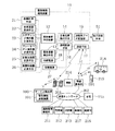
図1は、本実施形態による緊急事態通報システムの全体構成を示している。緊急事態通報システムは、自動車に搭載されている車載用緊急事態通報装置11と、緊急通報サービス拠点局100に設置された緊急事態連絡装置101とを有している。
【0020】
車載用緊急事態通報装置11は、通信機能付きのコンピュータにより構成され、緊急事態予測手段12と、緊急事態検出手段13と、GPS等による自車位置検出手段14と、通報先データ記憶部15と、通報制御手段16と、通信手段17と、内部電源18とを含んでいる。
【0021】
車載用緊急事態通報装置11は、車載電源(バッテリ)27を通常電源としており、非常時電源として内部電源18を使用する。なお、この電源については、図2を参照して詳細を後述する。
【0022】
緊急事態予測手段12は、車間距離等、衝突対象物との距離を計測する距離計測手段21、自車速度計測手段22、ステアリング操作量計測手段23、ブレーキペダル操作量計測手段24、自車加速度計測手段25、表情特徴量計測手段26の各々より計測値を入力し、これら計測値に基づいて車両衝突等の緊急事態になる予測値を演算等によって決定する。
【0023】
緊急事態予測手段12は、緊急事態になる予測演算として、たとえば、距離計測手段21により計測される衝突対象物との距離と、自車速度計測手段22により計測される自車速度と、自車加速度計測手段25により計測される加速度と、ステアリング操作量計測手段23により計測されるステアリング操作量より、所定の時間後の自車位置と衝突対象物の位置とを予測し、予測した双方の位置関係より衝突の有無を推定する。
【0024】
車載用緊急事態通報装置11は、車両の自己診断を行う自己診断手段51と接続され、自己診断手段51による車両の自己診断結果を入力する。自己診断手段51は、車両のエンジン始動時や停止時に自己診断を行い、その自己診断結果は通信手段17によって緊急通報サービス拠点局100へ送信される。
距離計測手段21は、レーダ等により、自車と前方先行車等の前方の衝突対象物との距離や、自車と側方走行車等の側方の衝突対象物との距離等、衝突対象物との距離を計測する。
【0025】
表情特徴量計測手段26は、車載に設置されたCCDカメラ等によって運転者の顔を撮像し、その画像データより画像処理技術によって運転者の顔の表情特徴量を計測するものである。
緊急事態検出手段13は、二つの加速度スイッチと加速度センサ及びCPUからなり、車両の加速度に基づいて緊急事態を検出する(詳細は、図12、13及びその説明参照)。
【0026】
緊急通報サービス拠点局100の緊急事態連絡装置101は、通信機能付きのコンピュータにより構成され、無線基地局201、公衆電話回線網等による通信ネットワーク202による通信ライン、通信衛星203による衛星通信等によって車載用緊急事態通報装置11と双方向に通信可能に接続されている。
【0027】
緊急事態連絡装置101は、通信ネットワーク202によって、各々通信端末として、道路管理事務所211、警察署212、消防署213、病院214と通信可能になっており、また、緊急事態通報車の乗員(被サービス運転者)に関係する関係者通信端末として、被サービス運転者の自宅の電話機(以下、自宅)215と、被サービス運転者の親戚宅の電話機(以下、親戚宅)216と、被サービス運転者の事務所の電話機(以下、事務所)217等と回線接続可能になっている。
また、無線基地局201は、救急車218や、被サービス運転者の関係者が所有している携帯電話機219と通信可能になっている。
【0028】
つぎに、車載用緊急事態通報装置11の電源について、図2を参照して説明する。
車載電源27は、イグニッションキースイッチと連動の電源スイッチ28により車載用緊急事態通報装置11に対する電力供給をオン・オフし、安定化素子29によって電圧、電流の変動を抑えられる。
【0029】
内部電源18は、充電可能な電池等により構成されたバックアップ電源であり、通報制御手段16が出力する制御信号によって動作する充電・給電回路30により充電モードと給電モードとに切り替わるものであり、車載用緊急事態通報装置11に与えられる車載電源27の電圧が規定値以上である場合には充電モードとなって充電され、車載用緊急事態通報装置11に与えられる車載電源27の電圧が規定値未満に低下すると給電モードになり、車載電源27に代えて内部電源18で車載用緊急事態通報装置11に対して電力供給を行う。
【0030】
つぎに、車載用緊急事態通報装置11が行う処理を図3、図4に示されているフローチャートを参照して説明する。
この処理フローは、エンジン始動時の電源オンで開始され、まず、エンジン始動時に行われる車両の自己診断の終了を待ち(ステップS11)、自己診断結果を取得する(ステップS12)。そして、自車位置を検出し(ステップS13)、自車位置情報と共に、自己診断結果を緊急通報サービス拠点局100へ送信する(ステップS14)。自車位置は、グローバルポジショニングシステム(GPS)や、路上の通信設備、セルラー電話を使って検出することが可能である。
以上が、エンジン始動時の初期処理であり、エンジン始動時の初期処理が完了すると、緊急事態通報処理が開始される。
【0031】
緊急事態通報処理では、まず、自車位置を検出し(ステップS15)、自車位置検出後に緊急事態予測ルーチンを呼び出し、緊急事態予測ルーチンを実行する(ステップS16)。緊急事態予測るルーチンにより緊急事態予測が行われ、緊急事態予測ルーチンが終了すると、予測値を取得し(ステップS17)、予測値が所定値以上であるか否かの判別を行う(ステップS18)。予測値が所定値以上であると云うことは、所定時間後に緊急事態に陥ることを意味し、この場合には(ステップS18肯定)、事前通知として、自車位置情報と共にその予測結果を緊急通報サービス拠点局100へ送信する(ステップS19)。その後、予測通知フラグをセットし(ステップS20)、緊急事態検出ステップ(ステップS24)へ進む。
【0032】
これに対し、予測値が所定値未満であると云うことは、所定時間後に緊急事態に陥ることがないことを意味し、この場合には(ステップS18否定)、予測通知フラグがセットされているかをチェックする(ステップS21)。
予測通知フラグがセットされていれば(ステップS21肯定)、回避通知を緊急通報サービス拠点局100に対して行い(ステップS22)、予測通知フラグをクリアし(ステップS23)、緊急事態検出ステップ(ステップS24)へ進む。予測通知フラグがセットされていなければ(ステップS21否定)、直接、緊急事態検出ステップ(ステップS24)へ進む。
【0033】
緊急事態検出ステップ(ステップS24)では、緊急事態検出を行い、その検出結果より緊急事態であるか否かを判別する(ステップS25)。
緊急事態でない場合には(ステップS25否定)、エンジンの運転停止により車載電源がオフされたか否かをチェックする(ステップS26)。車載電源オフでない場合には(ステップS26否定)、ステップS15に戻り、ループする。
【0034】
エンジンの運転停止により車載電源がオフされた場合には(ステップS26肯定)、予測通知フラグがセットされているかをチェックする(ステップS27)。予測通知フラグがセットされていれば(ステップS27肯定)、回避通知を緊急通報サービス拠点局100に対して行い(ステップS28)、予測通知フラグをクリアする(ステップS29)。
【0035】
そして、エンジン停止時に行われる車両の自己診断の終了を待ち(ステップS30)、自己診断結果を取得する(ステップS31)。そして、最新の自車位置情報と共に、自己診断結果を緊急通報サービス拠点局100へ送信する(ステップS32)。
【0036】
これに対し、緊急事態である場合には(ステップS25肯定)、最新の自車位置情報と共に、緊急事態検出結果を緊急通報サービス拠点局100へ送信し(ステップS33)、その後、緊急通報サービス拠点局100よりの着信確認の返信を待ち(ステップS34)、緊急通報サービス拠点局100との通信回線を確保(接続維持)する(ステップS35)。なお、緊急通報サービス拠点局100から着信確認の返信を受信できない場合には、複数回送信を試行した後、運転者にその旨を報知することができる。
サービス隊、救急隊の到着し、車載電源がオフされると(ステップS36肯定)、通信回線を遮断(接続解除)する(ステップS37)。
【0037】
つぎに、緊急事態予測ルーチンの1例を図5に示されているフローチャートを参照して説明する。
まず、自車と前方の衝突対象物との距離と、自車と側方の衝突対象物との車間距離の検出(ステップS41)、過去の距離の取得(ステップS42)、自車速の検出(ステップS43)、過去の自車速の取得(ステップS44)、加速度の検出(ステップS45)、過去の加速度の取得(ステップS46)、ステアリング操作量の検出(ステップS47)、過去のステアリング操作量の取得(ステップS48)を順に行う。
【0038】
上述の情報検出、取得が完了すれば、これらの情報をもとにして1秒後の自車位置を、現在の自車位置を基準点にして計算する(ステップS49)。つぎに、1秒後の対象物位置を、現在の自車位置を基準点にして計算し(ステップS50)、1秒後の自車位置と1秒後の対象物位置とを比較して衝突するか否かの判定を行う(ステップS51)。
1秒後に衝突していると予測判定した場合には(ステップS51肯定)、衝突フラグをセットする(ステップS58)。
【0039】
これに対し、衝突しないと予測判定した場合には(ステップS51否定)、つぎに、同様に、2秒後の自車位置を、現在の自車位置を基準点にして計算する(ステップS52)。つぎに、同様に、2秒後の対象物位置を、現在の自車位置を基準点にして計算し(ステップS53)、2秒後の自車位置と1秒後の対象物位置とを比較して衝突するか否かの判定を行う(ステップS54)。
2秒後に衝突していると予測判定した場合には(ステップS54肯定)、衝突フラグをセットする(ステップS58)。
【0040】
これに対し、衝突しないと予測判定した場合には、ブレーキペダル操作量の検出(ステップS55)、過去のブレーキペダル操作量の取得(ステップS56)を行い、ブレーキペダル操作量と、自車と前方の衝突対象物との距離から、衝突の有無を判定する(ステップS57)。衝突すると予測判定した場合には(ステップS54肯定)、衝突フラグをセットする(ステップS58)。これに対し、衝突しないと予測判定した場合には、衝突フラグをクリアする(ステップS59)。
【0041】
ここで、衝突フラグがセットされたことは、緊急事態の予測値が所定値以上であることと同じでことであり、衝突フラグをクリアすることは、緊急事態の予測値が未満であることと同じでことである。
上述した処理フローにより緊急事態予測がより確実なものになる。
【0042】
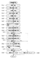
つぎに、緊急通報サービス拠点局100に設置されている緊急事態連絡装置101が行う緊急連絡処理を図6に示されているフローチャートを参照して説明する。
緊急事態連絡装置101は、車載用緊急事態通報装置11からの通報を受信すべく常時待機しており、車載用緊急事態通報装置11から緊急事態の予測通知を受信すると(ステップS61)、車載用緊急事態通報装置11からの予測通知内容を第1情報として記憶し、予測受信フラグをセットし、タイマをオンする(ステップS62)。
【0043】
つぎに、車載用緊急事態通報装置11から緊急事態通知の受信の有無を判別する(ステップS63)。緊急事態通知を受信すると(ステップS63肯定)、通知元の車載用緊急事態通報装置11との通信回線を確保(接続維持)し(ステップS65)、緊急事態通知内容を第1情報として記憶する(ステップS65)。そして、救急出動機関に対してサービス隊、救急隊の出動要請の連絡を行い(ステップS66)、第1情報を、車載用緊急事態通報装置11との通信回線とは別の通信回線によって、消防署213、道路管理事務所211、警察署212、自宅215、親戚宅216、事務所217の順に連絡する(ステップS67)。また、各所に送信する第1情報は、車載用緊急事態通報装置11にも送信する。
自宅215、親戚宅216、事務所217への通信において、他の場所への転送があった場合には(ステップS68肯定)、転送先検索の通信処理を行う(ステップS69)。
【0044】
緊急事態通知を受信しない場合には(ステップS63否定)、つぎに、車載用緊急事態通報装置11よりの受信の有無をチェックする(ステップS70)。回避通知を受信すれば(ステップS70肯定)、車載用緊急事態通報装置11からの予測通知内容(第1情報)、予測受信フラグ、タイマを全てクリアする(ステップS71)。
【0045】
これに対し、回避通知を受信しない場合には(ステップS70否定)、予測受信フラグがセットされているかをチェックし(ステップS72)、予測受信フラグがセットされている場合には(ステップS72肯定)、タイマ値をチェックする(ステップS73)。
【0046】
ここで、タイマ値が所定値以上であると云うことは(ステップS73肯定)、車載用緊急事態通報装置11が緊急事態の予測通知を出してから、所定時間が経過しも、回避通知、緊急事態通知の何れもない状態にあることを指す。この状態は、緊急事態の発生により車載用緊急事態通報装置11が通信不能に陥っている可能性が高いと推測され、緊急事態が発生したと断定する。
【0047】
この場合も、救急出動機関に対してサービス隊、救急隊の出動要請の連絡を行い(ステップS66)、第1情報を、車載用緊急事態通報装置11との通信回線とは別の通信回線によって、消防署213、道路管理事務所211、警察署212、自宅215、親戚宅216、事務所217の順に連絡する(ステップS67)。
【0048】
つぎに、転送先検索の通信処理(ステップS69)の具体例を図7に示されているタイムチャートを参照して説明する。ここでは、自宅(電話機)215に、携帯電話機219への転送が設定されている場合を例にとって説明する。
緊急通報サービス拠点局100(緊急事態連絡装置101)が第1情報を自宅215へ送信する通信を行った結果、自宅215に転送設定がされていると、不在情報が緊急通報サービス拠点局100に帰る。これを受けて、緊急通報サービス拠点局100は、転送先に送信したい第1情報と転送先電話番号を緊急通報サービス拠点局100へ自動送信するためのコンピュータ実行のプログラムを自宅215に送信し、通信を終了する。
【0049】
つぎに、自宅215は第1情報とプログラムを転送先である携帯電話219へ送信する。携帯電話219は、自宅215との転送通信が終了すると、受信したプログラムを起動し、プログラム実行によって転送先電話番号(自機電話番号)を緊急通報サービス拠点局100へ送信する。
【0050】
これにより、緊急通報サービス拠点局100から自宅215へ送信する第2通報(後述の第3情報の送信等)は、転送先へ直接送信することが可能になる。
また、緊急事態連絡装置101は、緊急事態通報車の位置情報を所定時間毎に受信し、緊急事態通報車の最新の位置情報を関係者の連絡先に送信することもできる。
【0051】
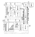
つぎに、サービス拠点100に設置されている緊急事態連絡装置101と、被サービス運転者が病院214に搬入された場合に使用される搬入先の病院端末(救急患者用情報端末220)の構成を図8を参照して説明する。
緊急事態連絡装置101は、通信機能付きのコンピュータにより構成され、連絡先データベース102と、第1情報を記憶する記憶手段103と、連絡制御手段104と、通信手段105とを有している。連絡先データベース102は、道路管理事務所211、警察署212、消防署213、病院(医院)214の電話番号以外に、被サービス運転者毎の個人情報として、自宅215、親戚宅216、事務所(秘書)217の電話番号を記憶している。
救急患者用情報端末220は、通信機能付きのコンピュータにより構成され、連絡制御手段221と、キーボード等の入力手段222と、CRT等による表示手段223と、通信手段224とを有している。
【0052】
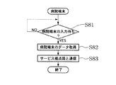
つぎに、救急患者用情報端末220の処理を図9に示されているフローチャートを参照して説明する。救急患者用情報端末(病院端末)220は、図10に示されているような入力画面の表示で入力待ちになっており(ステップS81)、救急患者が搬入されると、図10に示されているような入力画面で、搬入患者名、運転免許証番号(保険証番号)、カルテ番号、患者の容態(軽傷、重傷、重体、死亡)を入力されることで、各データを取得する(ステップS82)。
【0053】
入力画面で、送信ボタン225が押されると、第2情報として、病院名、病院の電話番号等の病院情報、患者の容態等を緊急通報サービス拠点局100へ送信する(ステップS83)。
緊急通報サービス拠点局100の緊急事態連絡装置101は、患者搬入の病院214より第2情報を受信すると、第1情報と第2情報とから第3情報を生成し、第3情報を患者(被サービス運転者)の登録されている連絡先へ連絡通信を行う。
【0054】
この連絡通信処理を図11に示されているフローチャートを参照して説明する。緊急事態連絡装置101は、着信待ちになっており(ステップS91)、病院端末220からの着信を受けると(ステップS92)、病院端末220から第2情報を取得する(ステップS93)。
【0055】
つぎに、記憶していた第1情報を取得し(ステップS94)、第1情報と第2情報とから第3情報を生成する(ステップS95)。そして、生成した第3情報を自宅215、親戚宅216、事務所217に順次連絡する。
これにより、事故発生後の乗員(被サービス運転者)の救急搬送先や運転者の安否が関係者に素早く的確に通報され、サービス性が向上する。
【0056】
図12は、緊急事態検出手段13の構成を示している。該緊急事態検出手段13は、加速度スイッチA301、加速度スイッチB302、加速度センサ303、及び、CPU304で構成されている。加速度スイッチA301は、予め決めてある加速度が計測されると通電状態(オン)になるスイッチであり、それ以外の状態はオフになるスイッチである。加速度スイッチB302は、加速度スイッチA301と同じであり、加速度センサ303は、加速度に比例して出力電圧が増減するものである。
【0057】
図13は、緊急事態検出手段13の制御処理フローを示したものである。まず、車載電源オンで自己診断をする(ステップS120)。その後、加速度スイッチAのオンまたはオフを判定する(ステップS121)。オンの場合は緊急事態フラグAをセットし(ステップS123)、オフの場合は緊急事態フラグAをクリアする(ステップS122)。次に加速度スイッチBのオンまたはオフを判定する(ステップS124)。オフの場合には緊急事態フラグBをセットし(ステップ126)、オフの場合は緊急事態フラグAをクリアする(ステップS125)。
【0058】
次に、加速度センサの出力を周波数分析をする(ステップS127)。そして、特定の周波数(40Hz〜60Hz)の成分が所定の大きさ(50m/s2)以上になっているか否かを判定する(ステップS128)。所定以上の場合には、緊急事態フラグCをセットし(ステップS130)、所定値未満の場合は緊急事態フラグCをクリアする(ステップS129)。
【0059】
そして、緊急事態フラグAと緊急事態フラグCが共にセットされている(ステップS131)、または、緊急事態フラグBと緊急事態フラグCが共にセットされている場合には(ステップS132)、緊急事態フラグDをセットし(ステップ134)、緊急事態フラグAと緊急事態フラグCが共にセットされず緊急事態フラグBと緊急事態フラグCが共にセットされない場合には緊急事態フラグDをクリアする(ステップS133)。そして、車載電源がオンしている場合にはステップS121に戻り、車載電源がオフしている場合には処理を終了する。
【0060】
図14は緊急事態通報テスト装置81を示している。緊急事態通報テスト装置81は、通報テスト手段82と、表示手段83と、車載用緊急事態通報装置11と通信する通信手段84とを有し、車載用緊急事態通報装置11より自己診断結果を受信してそれを表示手段83に画面表示し、受信完了を車載用緊急事態通報装置11へ送信し、その返信の有無を表示手段83に画面表示する。
【0061】
つぎに、緊急事態通報テスト装置81によるテスト時の緊急事態通報装置11の処理を図15に示されているフローチャートを参照して説明する。
この処理フローは電源オンで開始され、エンジン始動時に行われる車両の自己診断の終了を待ち(ステップS101)、自己診断結果を取得する(ステップS102)。そして、自己診断結果をテスト装置81へ送信する(ステップS103)。
【0062】
その後、テスト装置81よりの自己診断結果の受信応答(返信)を待ち(ステップS104)、テスト装置81より受信応答を受信することで、一連の通信が完了したことをテスト装置81へ通知する(ステップS105)。
この後、車載電源がオフされることを待ち(ステップS106)、車載電源がオフされれば、エンジン停止時に行われる車両の自己診断の終了を待ち(ステップS107)、自己診断結果を取得する(ステップS108)。そして、自己診断結果をテスト装置81へ送信する(ステップS109)。
その後、テスト装置81よりの自己診断結果の受信応答(返信)を待ち(ステップS110)、テスト装置81より受信応答を受信すれば、テストモードを終了し、次回の電源オンから通常動作できるように設定を変更する(ステップS111)。
【0063】
以上、本発明の一実施形態について詳述したが、本発明は、前記実施形態に限定されるものではなく、特許請求の範囲に記載した発明の精神を逸脱することなく、設計において種々の変更ができるものである。
【0064】
【発明の効果】
以上の説明から理解される如く、本発明による車載用緊急事態通報装置、緊急事態通報システムによれば、より多くの入力情報で危険度を検出することにより、緊急事態予測手段の正確さが増し、緊急事態後の運転者の安全性確保が確実に行えるようになり、併せて緊急事態通報システムの通信回線の必要容量の削減と、緊急通報サービス拠点局に設けられる緊急事態連絡装置の処理負荷を低減することができる。
また、本発明による緊急事態連絡装置によれば、緊急事態の発生後に、自宅待機者等の関係者に対して、運転者の安否や移動先をいち早く通報することができる。
【図面の簡単な説明】
【図1】本発明による緊急事態通報システムの全体構成を示す説明図である。
【図2】本発明による車載用緊急事態通報装置の電源装置の一つの実施の形態を示す回路図である。
【図3】本発明による車載用緊急事態通報装置の処理フロー(前半)を示すフローチャートである。
【図4】本発明による車載用緊急事態通報装置の処理フロー(後半)を示すフローチャートである。
【図5】本発明による車載用緊急事態通報装置の緊急事態予測ルーチンを示すフローチャートである。
【図6】本発明による緊急事態連絡装置の処理フローを示すフローチャートである。
【図7】本発明による緊急事態連絡装置における転送先検索通信処理を示すタイムチャートである。
【図8】本発明による緊急事態連絡装置と救急患者用情報端末(病院端末)とを示す説明図である。
【図9】病院端末の処理フローを示すフローチャートである。
【図10】病院端末の入力画面を示す説明図である。
【図11】本発明による緊急事態連絡装置の処理フローを示すフローチャートである。
【図12】本発明の緊急事態検出装置を示す説明図である。
【図13】本発明の緊急事態検出装置の処理フローを示すフローチャートである。
【図14】本発明による車載用緊急事態通報装置と緊急事態通報テスト装置とを示す説明図である。
【図15】本発明による車載用緊急事態通報装置のテスト通信時の処理フローを示すフローチャートである。
【符号の説明】
11 車載用緊急事態通報装置
12 緊急事態予測手段
13 緊急事態検出手段
14 自車位置検出手段
16 通報制御手段
18 内部電源
21 距離計測手段
22 自車速度計測手段
23 ステアリング操作量計測手段
24 ブレーキペダル操作量計測手段
25 自車加速度計測手段
26 表情特徴量計測手段
27 車載電源
100 緊急通報サービス拠点局
101 緊急事態連絡装置
102 連絡先データベース
104 連絡制御手段
212 警察署
213 消防署
214 病院
215 自宅
219 携帯電話機
220 救急患者用情報端末[0001]
BACKGROUND OF THE INVENTION
The present invention relates to an in-vehicle emergency notification device, an emergency notification device, and an emergency notification system, and in particular, an in-vehicle emergency notification device that notifies an emergency when an accident such as a collision occurs in a vehicle such as an automobile, The present invention relates to an emergency notification device and an emergency notification system.
[0002]
[Prior art]
Conventionally, various devices have been installed to ensure traveling safety in vehicles. However, even if the driving safety is improved by various devices, it is difficult to eliminate accidents. Therefore, when an emergency situation including an accident occurs, an emergency notification system that notifies an emergency situation to a predetermined organization is effective.
[0003]
An example of an emergency notification system is disclosed in Japanese Patent Laid-Open No. 10-162284. The emergency notification system shown in this gazette detects the position of the host vehicle, communicates information about the host vehicle position with the vehicle station, and performs bidirectional communication with the vehicle station. The Mayday Center prioritizes multiple emergency call destinations based on the location of the vehicle station when an emergency call is required for a vehicle station. Make emergency calls in order.
[0004]
In addition, this emergency notification system is based on the degree of danger in the travel route of the vehicle and the traveling state of the vehicle so that it can respond even when communication facilities are destroyed due to the occurrence of a vehicle accident. If the risk level is greater than or equal to the specified value, the time from entry to exit of the high risk area is predicted and an emergency notification is sent to the Mayday Center. The occurrence of an emergency situation is detected when communication is not recovered.
[0005]
[Problems to be solved by the invention]
Vehicle accidents often occur due to the presence of other vehicles, such as a collision accident between vehicles, in addition to the relationship between the traveling state of the vehicle and the shape of the road on which the vehicle is traveling. On the other hand, in the above-mentioned emergency notification system, input information is insufficient regarding the detection of the risk level, and even when the risk level is low, the emergency call service base station (Mayday Center) is notified in advance, and after a predetermined time, It is necessary to handle a lot of communications to cancel.
[0006]
For this reason, conventional emergency notification systems often increase the capacity of the communication line and increase the processing capacity of the emergency notification device installed in the emergency call service base station in advance in order to cancel in advance. It is necessary to keep it.
In addition, the emergency call service base station communicates with the driver's home based on the data sent from the emergency report device (vehicle station), and if the emergency is a property damage accident or a vehicle breakdown, In many cases, the driver himself is healthy, and it is sufficient for the driver himself to inform the home of the situation where the emergency occurred.
[0007]
However, when the emergency situation is a personal injury or poor physical condition, the driver himself / herself needs to be treated at the hospital, and it may be difficult to keep waiting near the emergency notification device (own vehicle). Even if an emergency notification device is used to contact the home on the spot, the information of the subsequent destination, most of the receiving hospitals, is unknown.
[0008]
The reason why the home is listed in the report to the parties concerned in the event of an emergency is that the driver is seeking help from a home standby person in the event of an emergency. In addition, the home waiter who received the report is interested not only in the driver's emergency situation, but also in knowing the driver's safety and destination as soon as possible. Can't cope with the request sufficiently.
[0009]
The present invention has been made to solve the above-described problems, and the purpose of the present invention is to increase the appropriateness of emergency prediction and ensure the operation of an accurate and reliable emergency notification. Can reduce the required capacity of the communication line of the emergency notification system, reduce the processing load of the emergency communication device installed at the base station of the emergency call service, etc. In-vehicle emergency notification device that can report the safety of the vehicle, automobile equipped with the in-vehicle emergency notification device, emergency notification test device for in-vehicle emergency notification device, emergency notification device and emergency notification To provide a system.
[0010]
[Means for Solving the Problems]
In order to achieve the above object, according to the present invention The emergency notification system is an emergency notification system including an emergency notification device and an in-vehicle emergency notification device, and the emergency notification device stores contact information of related parties. And the communication means, the emergency notification is received from the in-vehicle emergency notification device by the communication means, the emergency dispatch is requested to the emergency dispatching organization, and the vehicle occupant who made the emergency report is conveyed Receives hospital information and passenger safety status from the transported hospital, retrieves contact information of related persons related to the passenger from the contact database, and transports passengers to the contact information of the searched related persons The in-vehicle emergency notification device transmits the hospital information and the safety status of the occupant, Own vehicle position detecting means for detecting the own vehicle position; Opposition The emergency situation occurs after the vehicle has reached a predetermined time from at least one of the distance to the collision object, relative speed, relative acceleration, host vehicle speed, brake pedal operation amount, steering operation amount, and driver facial expression feature amount. Predict whether or not Emergency prediction means for performing the prediction, and communication means for transmitting the prediction result to the emergency call service base station together with the vehicle position information detected by the vehicle position detection means. The vehicle position after a predetermined time and the position of the collision object are predicted from the distance to the vehicle, the vehicle speed, the acceleration, and the steering operation amount, and the presence or absence of the collision is estimated from the predicted positional relationship. Have .
[0011]
According to the invention In the emergency notification system, when a forwarding destination is set in the contact phone of the related party that has been searched, the emergency notification device receives forwarding phone number information from the telephone or the forwarding phone. It is characterized by acquiring and contacting related parties to the forwarding telephone. .
[0012]
According to the in-vehicle emergency notification device according to the present invention configured as described above, the emergency prediction means includes a distance to the collision target (for example, an inter-vehicle distance), a relative speed, a relative acceleration, an own vehicle speed, and a brake. Predict that the vehicle will be in an emergency after a predetermined time from at least one of the pedal operation amount, the steering operation amount, and the driver's facial expression feature amount, for example, the distance to the collision object, the vehicle speed Since the vehicle position and the position of the collision target object after a predetermined time are predicted from the acceleration and the steering operation amount, and the presence / absence of the collision is estimated from the predicted positional relationship, the appropriateness of the emergency prediction increases, Enables accurate and reliable emergency reporting.
[0013]
The in-vehicle emergency notification device according to the present invention has an internal power source charged by an in-vehicle power source. The in-vehicle power source is a normal power source, and when the power supply by the in-vehicle power source is stopped, the internal power source Even if the power is supplied and the in-vehicle power supply goes down due to an accident, it maintains normal operation in an uninterruptible system.
The on-vehicle emergency notification device according to the present invention transmits the self-diagnosis result of the vehicle to the emergency notification service base station by the communication means.
[0014]
In order to achieve the above-mentioned object, the vehicle according to the present invention is equipped with the vehicle-mounted emergency notification device according to the above-described invention.
The emergency notification test device according to the present invention has communication means for communicating with the in-vehicle emergency notification device according to the above-described invention, receives a self-diagnosis result from the in-vehicle emergency notification device, and completes reception. It transmits to the said vehicle-mounted emergency notification apparatus.
[0016]
According to the emergency notification device according to the present invention configured as described above, when an emergency notification is received from the in-vehicle emergency notification device, in addition to requesting emergency dispatch from the emergency dispatch engine, the emergency notification vehicle Occupant transport Hospital information and passenger safety status Is received from the emergency station, contact information of related persons related to the passenger is retrieved from the contact database, and the passenger is transferred to the contact information of the related person. Hospital information and passenger safety status The person concerned is the destination of the occupant, such as information on the hospital And passenger safety Can be known quickly. The ambulance station is an emergency transport means such as an emergency hospital or ambulance at the transport destination, and the emergency hospital or ambulance at the transport destination transmits the transport destination information of the occupant to the emergency notification device.
[0017]
Ma In addition, the emergency notification device according to the present invention receives the location information of the emergency notification vehicle together with the emergency notification from the in-vehicle emergency notification device every predetermined time by the communication means, and the latest location of the emergency notification vehicle. Information can also be sent to the contacts of interested parties.
[0018]
In addition, the emergency contact device according to the present invention acquires transfer destination telephone number information from the telephone or the transfer destination telephone when the transfer destination is set in the telephone of the related party, Contact can be made directly to the destination telephone.
In order to achieve the above-described object, the emergency notification system according to the present invention includes an in-vehicle emergency notification device according to the above-described invention, and an emergency notification device according to the above-described invention installed in an emergency notification service base station. have.
[0019]
DETAILED DESCRIPTION OF THE INVENTION
Hereinafter, embodiments of the present invention will be described in detail with reference to the accompanying drawings.
FIG. 1 shows the overall configuration of the emergency notification system according to the present embodiment. The emergency notification system includes an in-vehicle
[0020]
The in-vehicle
[0021]
The in-vehicle
[0022]
The emergency state predicting means 12 includes a distance measuring means 21 for measuring a distance from a collision target such as an inter-vehicle distance, an own vehicle speed measuring means 22, a steering operation amount measuring means 23, a brake pedal operation amount measuring means 24, an own vehicle acceleration. A measurement value is input from each of the
[0023]
For example, the
[0024]
The in-vehicle
The distance measuring means 21 uses a radar or the like to detect a collision target such as a distance between the own vehicle and a front collision object such as a preceding vehicle ahead, a distance between the own vehicle and a side collision object such as a side traveling vehicle, or the like. Measure the distance to the object.
[0025]
The facial expression feature quantity measuring means 26 images the driver's face with a CCD camera or the like installed on the vehicle, and measures the facial expression feature quantity of the driver's face from the image data using an image processing technique.
The emergency detection means 13 includes two acceleration switches, an acceleration sensor, and a CPU, and detects an emergency based on the acceleration of the vehicle (for details, see FIGS. 12 and 13 and the description thereof).
[0026]
The
[0027]
The emergency
In addition, the
[0028]
Next, the power source of the vehicle-mounted
The in-
[0029]
The
[0030]
Next, processing performed by the in-vehicle
This processing flow is started when the power is turned on when the engine is started. First, the process waits for completion of the self-diagnosis of the vehicle that is performed when the engine is started (step S11), and a self-diagnosis result is acquired (step S12). Then, the vehicle position is detected (step S13), and the self-diagnosis result is transmitted to the emergency call
The above is the initial process at the time of starting the engine. When the initial process at the time of starting the engine is completed, the emergency notification process is started.
[0031]
In the emergency notification process, first, the vehicle position is detected (step S15), the emergency prediction routine is called after the vehicle position is detected, and the emergency prediction routine is executed (step S16). An emergency prediction is performed by the emergency prediction routine, and when the emergency prediction routine ends, a predicted value is acquired (step S17), and it is determined whether or not the predicted value is equal to or greater than a predetermined value (step S18). . If the predicted value is greater than or equal to the predetermined value, it means that an emergency situation will occur after a predetermined time. In this case (Yes in step S18), as a prior notification, the predicted result together with the vehicle position information is sent as an emergency call. It transmits to the service base station 100 (step S19). Thereafter, a prediction notification flag is set (step S20), and the process proceeds to an emergency detection step (step S24).
[0032]
On the other hand, if the predicted value is less than the predetermined value, it means that an emergency situation will not occur after a predetermined time. In this case (No at step S18), is the prediction notification flag set? Is checked (step S21).
If the prediction notification flag is set (Yes at step S21), an avoidance notification is sent to the emergency call service base station 100 (step S22), the prediction notification flag is cleared (step S23), and an emergency detection step (step) Proceed to S24). If the prediction notification flag is not set (No at Step S21), the process proceeds directly to the emergency detection step (Step S24).
[0033]
In the emergency detection step (step S24), emergency detection is performed, and it is determined from the detection result whether the situation is an emergency (step S25).
If it is not an emergency (No at Step S25), it is checked whether or not the in-vehicle power supply is turned off due to the engine stop (Step S26). If the on-vehicle power supply is not turned off (No at Step S26), the process returns to Step S15 and loops.
[0034]
When the vehicle-mounted power supply is turned off due to the engine stop (Yes at Step S26), it is checked whether the prediction notification flag is set (Step S27). If the prediction notification flag is set (Yes at Step S27), an avoidance notification is sent to the emergency call service base station 100 (Step S28), and the prediction notification flag is cleared (Step S29).
[0035]
And it waits for completion | finish of the self-diagnosis of the vehicle performed at the time of an engine stop (step S30), and acquires a self-diagnosis result (step S31). Then, the self-diagnosis result is transmitted to the emergency call
[0036]
On the other hand, in the case of an emergency (Yes at step S25), the emergency detection result is transmitted to the emergency call
When the service team or ambulance team arrives and the in-vehicle power supply is turned off (Yes at step S36), the communication line is disconnected (disconnected) (step S37).
[0037]
Next, an example of the emergency prediction routine will be described with reference to the flowchart shown in FIG.
First, the distance between the own vehicle and the front collision object and the distance between the own vehicle and the side collision object are detected (step S41), the past distance is acquired (step S42), and the own vehicle speed is detected (step S42). Step S43), acquisition of past vehicle speed (Step S44), detection of acceleration (Step S45), acquisition of past acceleration (Step S46), detection of steering operation amount (Step S47), acquisition of past steering operation amount (Step S48) is performed in order.
[0038]
If the above-mentioned information detection and acquisition are completed, the own vehicle position after 1 second is calculated based on these information using the current own vehicle position as a reference point (step S49). Next, the object position after 1 second is calculated using the current vehicle position as a reference point (step S50), and the vehicle position after 1 second is compared with the object position after 1 second to collide. It is determined whether or not to perform (step S51).
If it is determined that the collision has occurred after 1 second (Yes at Step S51), the collision flag is set (Step S58).
[0039]
On the other hand, if it is determined that the vehicle will not collide (No in step S51), the vehicle position after 2 seconds is calculated similarly using the current vehicle position as a reference point (step S52). . Next, similarly, the object position after 2 seconds is calculated using the current vehicle position as a reference point (step S53), and the vehicle position after 2 seconds is compared with the object position after 1 second. Then, it is determined whether or not the collision occurs (step S54).
If it is determined that the collision occurs after 2 seconds (Yes at Step S54), the collision flag is set (Step S58).
[0040]
On the other hand, when it is determined that there is no collision, the brake pedal operation amount is detected (step S55) and the past brake pedal operation amount is acquired (step S56). Whether or not there is a collision is determined from the distance to the collision object (step S57). If it is predicted to collide (Yes at Step S54), a collision flag is set (Step S58). On the other hand, when it is determined that there is no collision, the collision flag is cleared (step S59).
[0041]
Here, the fact that the collision flag is set is the same as that the predicted value of the emergency is equal to or greater than the predetermined value, and clearing the collision flag means that the predicted value of the emergency is less than The same is true.
The above-described processing flow makes emergency prediction more reliable.
[0042]
Next, emergency contact processing performed by the emergency
The
[0043]
Next, it is determined whether or not an emergency notification has been received from the in-vehicle emergency notification device 11 (step S63). When the emergency notification is received (Yes at Step S63), the communication line with the in-vehicle
In the communication to the
[0044]
When the emergency notification is not received (No at Step S63), the presence / absence of reception from the in-vehicle
[0045]
On the other hand, when the avoidance notification is not received (No at Step S70), it is checked whether the predicted reception flag is set (Step S72). When the predicted reception flag is set (Yes at Step S72). The timer value is checked (step S73).
[0046]
Here, if the timer value is equal to or greater than the predetermined value (Yes at Step S73), the avoidance notification, the emergency notification, even if a predetermined time elapses after the in-vehicle
[0047]
In this case as well, the service team and the emergency team dispatch request are communicated to the emergency dispatch organization (step S66), and the first information is transmitted through a communication line different from the communication line with the in-vehicle
[0048]
Next, a specific example of the communication process (step S69) for forwarding destination search will be described with reference to the time chart shown in FIG. Here, a case where transfer to the
When the emergency call service base station 100 (emergency state communication device 101) performs communication for transmitting the first information to the
[0049]
Next, the
[0050]
As a result, the second notification (such as transmission of third information described later) transmitted from the emergency notification
Further, the
[0051]
Next, the configuration of the
The
The emergency
[0052]
Next, the process of the emergency
[0053]
When the
Upon receiving the second information from the
[0054]
This communication process will be described with reference to the flowchart shown in FIG. The emergency
[0055]
Next, the stored first information is acquired (step S94), and third information is generated from the first information and the second information (step S95). Then, the generated third information is sequentially communicated to the
As a result, the emergency transport destination of the occupant (serviced driver) after the accident and the safety of the driver are notified to the concerned person quickly and accurately, and the serviceability is improved.
[0056]
FIG. 12 shows the configuration of the emergency detection means 13. The emergency state detection means 13 includes an acceleration switch A301, an acceleration switch B302, an
[0057]
FIG. 13 shows the control processing flow of the emergency detection means 13. First, self-diagnosis is performed by turning on the vehicle-mounted power supply (step S120). Thereafter, it is determined whether the acceleration switch A is on or off (step S121). When it is on, the emergency flag A is set (step S123), and when it is off, the emergency flag A is cleared (step S122). Next, it is determined whether the acceleration switch B is on or off (step S124). If it is off, the emergency flag B is set (step 126). If it is off, the emergency flag A is cleared (step S125).
[0058]
Next, frequency analysis is performed on the output of the acceleration sensor (step S127). And it is determined whether the component of a specific frequency (40 Hz-60 Hz) is more than predetermined magnitude | size (50 m / s2) (step S128). If it is not less than the predetermined value, the emergency flag C is set (step S130), and if it is less than the predetermined value, the emergency flag C is cleared (step S129).
[0059]
When both the emergency flag A and the emergency flag C are set (step S131), or when both the emergency flag B and the emergency flag C are set (step S132), the emergency flag D is set (step 134). If neither the emergency flag A nor the emergency flag C is set and neither the emergency flag B nor the emergency flag C is set, the emergency flag D is cleared (step S133). . If the in-vehicle power source is on, the process returns to step S121, and if the in-vehicle power source is off, the process ends.
[0060]
FIG. 14 shows an emergency
[0061]
Next, processing of the
This processing flow starts when the power is turned on, waits for the completion of the self-diagnosis of the vehicle that is performed when the engine is started (step S101), and acquires the self-diagnosis result (step S102). Then, the self-diagnosis result is transmitted to the test apparatus 81 (step S103).
[0062]
After that, it waits for a reception response (reply) of the self-diagnosis result from the test device 81 (step S104), and receives the reception response from the
Thereafter, the system waits for the in-vehicle power supply to be turned off (step S106). If the in-vehicle power supply is turned off, it waits for the completion of the vehicle self-diagnosis performed when the engine is stopped (step S107), and acquires the self-diagnosis result (step S107). Step S108). Then, the self-diagnosis result is transmitted to the test apparatus 81 (step S109).
After that, it waits for the reception response (reply) of the self-diagnosis result from the test device 81 (step S110), and if the reception response is received from the
[0063]
Although one embodiment of the present invention has been described in detail above, the present invention is not limited to the above-described embodiment, and various changes in design can be made without departing from the spirit of the invention described in the claims. It is something that can be done.
[0064]
【The invention's effect】
As understood from the above description, according to the in-vehicle emergency notification device and the emergency notification system according to the present invention, the accuracy of the emergency prediction means is increased by detecting the danger level with more input information. In addition, it is now possible to ensure the safety of the driver after an emergency, and at the same time, reduce the required capacity of the communication line of the emergency notification system and the processing load of the emergency communication device installed in the emergency notification service base station Can be reduced.
Moreover, according to the emergency notification apparatus by this invention, after the occurrence of an emergency, it is possible to promptly notify the safety of the driver and the travel destination to related parties such as a home standby person.
[Brief description of the drawings]
FIG. 1 is an explanatory diagram showing the overall configuration of an emergency notification system according to the present invention.
FIG. 2 is a circuit diagram showing an embodiment of a power supply device for an in-vehicle emergency notification device according to the present invention.
FIG. 3 is a flowchart showing a processing flow (first half) of the in-vehicle emergency notification device according to the present invention.
FIG. 4 is a flowchart showing a processing flow (second half) of the in-vehicle emergency notification device according to the present invention.
FIG. 5 is a flowchart showing an emergency prediction routine of the in-vehicle emergency notification device according to the present invention.
FIG. 6 is a flowchart showing a processing flow of the emergency communication device according to the present invention.
FIG. 7 is a time chart showing a forwarding destination search communication process in the emergency contact apparatus according to the present invention.
FIG. 8 is an explanatory diagram showing an emergency state communication device and an emergency patient information terminal (hospital terminal) according to the present invention.
FIG. 9 is a flowchart showing a processing flow of a hospital terminal.
FIG. 10 is an explanatory diagram showing an input screen of a hospital terminal.
FIG. 11 is a flowchart showing a processing flow of the emergency contact device according to the present invention.
FIG. 12 is an explanatory view showing an emergency detection device of the present invention.
FIG. 13 is a flowchart showing a processing flow of the emergency detection device of the present invention.
FIG. 14 is an explanatory diagram showing an in-vehicle emergency notification device and an emergency notification test device according to the present invention.
FIG. 15 is a flowchart showing a processing flow at the time of test communication of the in-vehicle emergency notification device according to the present invention.
[Explanation of symbols]
11 Vehicle emergency notification device
12 Emergency prediction means
13 Emergency detection means
14 Vehicle position detection means
16 Report control means
18 Internal power supply
21 Distance measuring means
22 Vehicle speed measurement means
23 Steering operation amount measuring means
24 Brake pedal operation amount measurement means
25 Vehicle acceleration measurement means
26 Facial expression feature measurement means
27 On-vehicle power supply
100 Emergency call service base station
101 Emergency communication device
102 Contact database
104 Contact control means
212 Police station
213 Fire department
214 Hospital
215 home
219 mobile phone
220 Information terminal for emergency patients
Claims (4)
前記緊急事態連絡装置は、関係者の連絡先情報を格納した連絡先データベースと、通信手段とを備え、
前記通信手段によって車載用緊急事態通報装置より緊急事態通報を受信して救急出動を救急出動機関に要請し、
前記緊急事態通報を行った車両の乗員が搬送された病院情報と乗員の安否状態を当該搬送された病院より受信し、
当該乗員に関係する関係者の連絡先情報を前記連絡先データベースより検索し、
検索された前記関係者の連絡先に乗員の搬送された病院情報と乗員の安否状態を送信し、
前記車載用緊急事態通報装置は、自車位置を検出する自車位置検出手段と、衝突対象物との距離、相対速度、相対加速度、自車速度、ブレーキペダル操作量、ステアリング操作量、運転者の表情の特徴量の少なくともいずれか一つから、自車が所定の時間後に緊急事態に陥るか否かを予測する緊急事態予測手段と、当該予測結果を前記自車位置検出手段により検出される自車位置情報と共に緊急通報サービス拠点局へ送信する通信手段とを備え、
前記緊急事態予測手段は、衝突対象物との距離、自車速度、加速度、ステアリング操作量より所定の時間後の自車位置と衝突対象物の位置とを予測し、予測した双方の位置関係より衝突の有無を推定することを特徴とする緊急事態通報システム。 An emergency notification system comprising an emergency notification device and an in-vehicle emergency notification device,
The emergency contact device includes a contact database storing contact information of related parties, and communication means.
By receiving an emergency notification from the in-vehicle emergency notification device by the communication means and requesting emergency dispatch to the emergency dispatch organization,
The hospital information and the safety status of the occupant who was transported by the vehicle occupant who made the emergency notification were received from the transported hospital.
Search the contact database for contact information of the parties related to the passenger,
The hospital information of the occupant transported and the safety status of the occupant are sent to the contact information of the related person that has been searched ,
The in-vehicle emergency notification device includes a distance between a vehicle position detection unit that detects the vehicle position and a collision target, a relative speed, a relative acceleration, a vehicle speed, a brake pedal operation amount, a steering operation amount, and a driver. An emergency prediction means for predicting whether or not the vehicle falls into an emergency situation after a predetermined time from at least one of the facial expression feature values, and the prediction result is detected by the vehicle position detection means Communication means for transmitting to the emergency call service base station together with the vehicle location information,
The emergency prediction means predicts the position of the vehicle and the position of the collision object after a predetermined time from the distance to the collision object, the vehicle speed, acceleration, and the steering operation amount, and from the predicted positional relationship An emergency notification system characterized by estimating the presence or absence of a collision .
Priority Applications (3)
| Application Number | Priority Date | Filing Date | Title |
|---|---|---|---|
| JP2001395267A JP4033672B2 (en) | 2001-12-26 | 2001-12-26 | Emergency notification system |
| US10/084,665 US6768417B2 (en) | 2001-12-26 | 2002-02-28 | On-vehicle emergency report apparatus, emergency communication apparatus and emergency report system |
| US10/244,540 US6724321B2 (en) | 2001-12-26 | 2002-09-17 | On-vehicle emergency report apparatus, emergency communication apparatus and emergency report system |
Applications Claiming Priority (1)
| Application Number | Priority Date | Filing Date | Title |
|---|---|---|---|
| JP2001395267A JP4033672B2 (en) | 2001-12-26 | 2001-12-26 | Emergency notification system |
Publications (3)
| Publication Number | Publication Date |
|---|---|
| JP2003196795A JP2003196795A (en) | 2003-07-11 |
| JP2003196795A5 JP2003196795A5 (en) | 2004-11-18 |
| JP4033672B2 true JP4033672B2 (en) | 2008-01-16 |
Family
ID=19188954
Family Applications (1)
| Application Number | Title | Priority Date | Filing Date |
|---|---|---|---|
| JP2001395267A Expired - Fee Related JP4033672B2 (en) | 2001-12-26 | 2001-12-26 | Emergency notification system |
Country Status (2)
| Country | Link |
|---|---|
| US (2) | US6768417B2 (en) |
| JP (1) | JP4033672B2 (en) |
Families Citing this family (64)
| Publication number | Priority date | Publication date | Assignee | Title |
|---|---|---|---|---|
| US7044742B2 (en) * | 2001-12-26 | 2006-05-16 | Kabushikikaisha Equos Research | Emergency reporting apparatus |
| JP3860552B2 (en) * | 2003-03-25 | 2006-12-20 | 富士通株式会社 | Imaging device |
| JP4135584B2 (en) * | 2003-07-15 | 2008-08-20 | トヨタ自動車株式会社 | In-vehicle collision response system |
| JP4528904B2 (en) * | 2003-07-23 | 2010-08-25 | 株式会社富士通エフサス | Vehicle collision accident information notification device |
| DE10338759A1 (en) * | 2003-08-23 | 2005-03-17 | Daimlerchrysler Ag | Device of a motor vehicle for the provision of accident-related data |
| US9311676B2 (en) | 2003-09-04 | 2016-04-12 | Hartford Fire Insurance Company | Systems and methods for analyzing sensor data |
| US7711584B2 (en) | 2003-09-04 | 2010-05-04 | Hartford Fire Insurance Company | System for reducing the risk associated with an insured building structure through the incorporation of selected technologies |
| US7610210B2 (en) * | 2003-09-04 | 2009-10-27 | Hartford Fire Insurance Company | System for the acquisition of technology risk mitigation information associated with insurance |
| US7096852B2 (en) * | 2003-10-30 | 2006-08-29 | Immersion Corporation | Haptic throttle devices and methods |
| US7212111B2 (en) * | 2003-12-30 | 2007-05-01 | Motorola, Inc. | Method and system for use in emergency notification and determining location |
| US7783505B2 (en) | 2003-12-30 | 2010-08-24 | Hartford Fire Insurance Company | System and method for computerized insurance rating |
| US8090599B2 (en) | 2003-12-30 | 2012-01-03 | Hartford Fire Insurance Company | Method and system for computerized insurance underwriting |
| US20060015689A1 (en) * | 2004-07-15 | 2006-01-19 | International Business Machines Corporation | Implementation and management of moveable buffers in cache system |
| US7823169B1 (en) | 2004-10-28 | 2010-10-26 | Wheeler Thomas T | Performing operations by a first functionality within a second functionality in a same or in a different programming language |
| US7774789B1 (en) | 2004-10-28 | 2010-08-10 | Wheeler Thomas T | Creating a proxy object and providing information related to a proxy object |
| US8266631B1 (en) | 2004-10-28 | 2012-09-11 | Curen Software Enterprises, L.L.C. | Calling a second functionality by a first functionality |
| US7797688B1 (en) | 2005-03-22 | 2010-09-14 | Dubagunta Saikumar V | Integrating applications in multiple languages |
| US7861212B1 (en) | 2005-03-22 | 2010-12-28 | Dubagunta Saikumar V | System, method, and computer readable medium for integrating an original application with a remote application |
| US8578349B1 (en) | 2005-03-23 | 2013-11-05 | Curen Software Enterprises, L.L.C. | System, method, and computer readable medium for integrating an original language application with a target language application |
| JP4760277B2 (en) * | 2005-10-04 | 2011-08-31 | トヨタ自動車株式会社 | Vehicle control device |
| JP4735267B2 (en) * | 2006-01-10 | 2011-07-27 | 株式会社デンソー | In-vehicle emergency call device |
| US7548805B2 (en) * | 2006-03-27 | 2009-06-16 | Fujitsu Ten Limited | Vehicle control apparatus, vehicle control method and vehicle slip suppressing apparatus |
| US7810140B1 (en) | 2006-05-23 | 2010-10-05 | Lipari Paul A | System, method, and computer readable medium for processing a message in a transport |
| US20080077451A1 (en) * | 2006-09-22 | 2008-03-27 | Hartford Fire Insurance Company | System for synergistic data processing |
| US8359209B2 (en) | 2006-12-19 | 2013-01-22 | Hartford Fire Insurance Company | System and method for predicting and responding to likelihood of volatility |
| US7702604B1 (en) | 2006-12-22 | 2010-04-20 | Hauser Robert R | Constructing an agent that utilizes supplied rules and rules resident in an execution environment |
| US7945497B2 (en) * | 2006-12-22 | 2011-05-17 | Hartford Fire Insurance Company | System and method for utilizing interrelated computerized predictive models |
| US7860517B1 (en) | 2006-12-22 | 2010-12-28 | Patoskie John P | Mobile device tracking using mobile agent location breadcrumbs |
| US8423496B1 (en) | 2006-12-22 | 2013-04-16 | Curen Software Enterprises, L.L.C. | Dynamic determination of needed agent rules |
| US8200603B1 (en) | 2006-12-22 | 2012-06-12 | Curen Software Enterprises, L.L.C. | Construction of an agent that utilizes as-needed canonical rules |
| US7664721B1 (en) | 2006-12-22 | 2010-02-16 | Hauser Robert R | Moving an agent from a first execution environment to a second execution environment using supplied and resident rules |
| US7970724B1 (en) | 2006-12-22 | 2011-06-28 | Curen Software Enterprises, L.L.C. | Execution of a canonical rules based agent |
| US7702603B1 (en) | 2006-12-22 | 2010-04-20 | Hauser Robert R | Constructing an agent that utilizes a compiled set of canonical rules |
| US8132179B1 (en) | 2006-12-22 | 2012-03-06 | Curen Software Enterprises, L.L.C. | Web service interface for mobile agents |
| US7660780B1 (en) | 2006-12-22 | 2010-02-09 | Patoskie John P | Moving an agent from a first execution environment to a second execution environment |
| US7949626B1 (en) | 2006-12-22 | 2011-05-24 | Curen Software Enterprises, L.L.C. | Movement of an agent that utilizes a compiled set of canonical rules |
| US7660777B1 (en) | 2006-12-22 | 2010-02-09 | Hauser Robert R | Using data narrowing rule for data packaging requirement of an agent |
| US7702602B1 (en) | 2006-12-22 | 2010-04-20 | Hauser Robert R | Moving and agent with a canonical rule from one device to a second device |
| US7698243B1 (en) | 2006-12-22 | 2010-04-13 | Hauser Robert R | Constructing an agent in a first execution environment using canonical rules |
| US9311141B2 (en) | 2006-12-22 | 2016-04-12 | Callahan Cellular L.L.C. | Survival rule usage by software agents |
| JP4245059B2 (en) * | 2007-02-27 | 2009-03-25 | 株式会社デンソー | In-vehicle emergency call device |
| KR100768942B1 (en) * | 2007-04-09 | 2007-10-19 | 삼정정보통신(주) | Image processing apparatus |
| US20090043615A1 (en) * | 2007-08-07 | 2009-02-12 | Hartford Fire Insurance Company | Systems and methods for predictive data analysis |
| US9665910B2 (en) | 2008-02-20 | 2017-05-30 | Hartford Fire Insurance Company | System and method for providing customized safety feedback |
| DE112008003932B4 (en) * | 2008-07-11 | 2022-04-28 | Elektrobit Automotive Gmbh | Technique for transmitting a message to a destination via vehicle-to-vehicle communication |
| JP2010120139A (en) * | 2008-11-21 | 2010-06-03 | New Industry Research Organization | Safety control device for industrial robot |
| US8208891B2 (en) * | 2009-05-01 | 2012-06-26 | At&T Intellectual Property I, L.P. | Methods and systems for relaying out of range emergency information |
| CN102576486A (en) * | 2009-08-26 | 2012-07-11 | 大陆汽车有限责任公司 | Systems and methods for emergency arming of a network access device |
| TWI399707B (en) * | 2009-10-30 | 2013-06-21 | Quanta Comp Inc | Traffic control system and method using positioned data |
| US8355934B2 (en) * | 2010-01-25 | 2013-01-15 | Hartford Fire Insurance Company | Systems and methods for prospecting business insurance customers |
| US20110210835A1 (en) * | 2010-03-01 | 2011-09-01 | Denso Corporation | Emergency notification system and method for notifying emergency |
| US9460471B2 (en) | 2010-07-16 | 2016-10-04 | Hartford Fire Insurance Company | System and method for an automated validation system |
| JP2012114625A (en) * | 2010-11-24 | 2012-06-14 | Nec Corp | Emergency radio connection system and emergency radio connection method |
| CN102426783B (en) * | 2011-08-30 | 2013-11-13 | 同济大学 | Low flow road traffic incident detection method based on vehicle tracking |
| JP6161951B2 (en) * | 2013-05-02 | 2017-07-12 | エレクトロビット オートモーティブ ゲーエムベーハー | Method for transferring a message to a target destination via communication between vehicles |
| US9449435B2 (en) * | 2013-10-23 | 2016-09-20 | Verizon Telematics Inc. | Accelerometer and voltage based key-on and key-off detection |
| US9707942B2 (en) | 2013-12-06 | 2017-07-18 | Elwha Llc | Systems and methods for determining a robotic status of a driving vehicle |
| US9164507B2 (en) * | 2013-12-06 | 2015-10-20 | Elwha Llc | Systems and methods for modeling driving behavior of vehicles |
| JP6552843B2 (en) * | 2015-03-05 | 2019-07-31 | 株式会社東芝 | POWER SUPPLY CONTROL DEVICE FOR MOBILE BODY, POWER SUPPLY CONTROL METHOD, AND POWER SUPPLY CONTROL SYSTEM APPLIED TO THIS POWER SUPPLY CONTROL DEVICE |
| US9820124B1 (en) * | 2016-09-27 | 2017-11-14 | GM Global Technology Operations LLC | System and method of emergency contact access during a critical event |
| US10394871B2 (en) | 2016-10-18 | 2019-08-27 | Hartford Fire Insurance Company | System to predict future performance characteristic for an electronic record |
| JP2019191855A (en) * | 2018-04-24 | 2019-10-31 | トヨタ自動車株式会社 | Vehicle accident information system |
| JP7449811B2 (en) * | 2020-07-31 | 2024-03-14 | 株式会社Subaru | Vehicle emergency communication device |
| DE102022116171A1 (en) * | 2021-07-21 | 2023-01-26 | Subaru Corporation | EMERGENCY REPORTING VEHICLE, AND SERVER |
Family Cites Families (6)
| Publication number | Priority date | Publication date | Assignee | Title |
|---|---|---|---|---|
| US6405132B1 (en) * | 1997-10-22 | 2002-06-11 | Intelligent Technologies International, Inc. | Accident avoidance system |
| JP3119182B2 (en) | 1996-12-04 | 2000-12-18 | トヨタ自動車株式会社 | Emergency call system |
| JP2000215372A (en) * | 1999-01-22 | 2000-08-04 | Matsushita Electric Ind Co Ltd | Emergency report system terminal device and emergency report system |
| US6262655B1 (en) * | 1999-03-29 | 2001-07-17 | Matsushita Electric Industrial Co., Ltd. | Emergency reporting system and terminal apparatus therein |
| US6567004B1 (en) * | 1999-12-28 | 2003-05-20 | Briartek, Inc. | Apparatus for automatically reporting an event to a remote location |
| US6456941B1 (en) * | 2001-03-26 | 2002-09-24 | William Gutierrez | System and method for aircraft and watercraft control and collision prevention |
-
2001
- 2001-12-26 JP JP2001395267A patent/JP4033672B2/en not_active Expired - Fee Related
-
2002
- 2002-02-28 US US10/084,665 patent/US6768417B2/en not_active Expired - Fee Related
- 2002-09-17 US US10/244,540 patent/US6724321B2/en not_active Expired - Fee Related
Also Published As
| Publication number | Publication date |
|---|---|
| US6724321B2 (en) | 2004-04-20 |
| JP2003196795A (en) | 2003-07-11 |
| US6768417B2 (en) | 2004-07-27 |
| US20030117274A1 (en) | 2003-06-26 |
| US20030117273A1 (en) | 2003-06-26 |
Similar Documents
| Publication | Publication Date | Title |
|---|---|---|
| JP4033672B2 (en) | Emergency notification system | |
| US20050037730A1 (en) | Mobile wireless phone with impact sensor, detects vehicle accidents/thefts, transmits medical exigency-automatically notifies authorities | |
| CN114466305A (en) | Rescue system, rescue method and server used by rescue system | |
| EP2266091A1 (en) | Roadside and emergency assistance system | |
| US11835349B2 (en) | Driving support apparatus, driving support system, and driving support method | |
| KR101565653B1 (en) | Requesting system for urgent rescue using pairing user terminal | |
| US20220215309A1 (en) | Information processing apparatus, information processing system, information processing method, and terminal apparatus | |
| WO2002035492A1 (en) | Moving object monitoring system, moving object monitoring apparatus, moving object monitoring method, move detecting method for moving object monitoring | |
| JP7085391B2 (en) | Servers and communication systems | |
| US11615500B2 (en) | Vehicle information processing apparatus, vehicle information processing system, and method of processing vehicle information | |
| US10647301B2 (en) | Monitoring system, monitoring center device, mounting device, monitoring method, processing method, and program | |
| US11391593B2 (en) | Vehicle-mounted device, server, navigation system, recording medium storing map display program, and map display method | |
| JP2022530056A (en) | Information processing systems for vehicles and how to process information for vehicles | |
| CN111128239A (en) | Emotion estimation device | |
| KR20130006910A (en) | Incident response system using black box for car and incident response method thereby | |
| US11956695B2 (en) | Server for automatic emergency reporting system of vehicle | |
| CN112002034A (en) | Vehicle accident rescue method, device, equipment and storage medium | |
| JP4259770B2 (en) | MOBILE TERMINAL DEVICE AND MOBILE BODY MONITORING SYSTEM | |
| JP2019219796A (en) | Vehicle travel control server, vehicle travel control method, and vehicle control device | |
| US20220230546A1 (en) | Vehicle dispatch management control device, vehicle dispatch management device, vehicle dispatch management system, vehicle dispatch management method, and computer program product | |
| KR100896907B1 (en) | Prestige Security System Using Telematics and Method thereof | |
| JP4240827B2 (en) | MOBILE TERMINAL DEVICE AND MOBILE BODY MONITORING SYSTEM | |
| JP2023074972A (en) | Information processing apparatus, method, and system | |
| JP2021060855A (en) | Emergency report system | |
| JP2002209268A (en) | Mobile terminal |
Legal Events
| Date | Code | Title | Description |
|---|---|---|---|
| A977 | Report on retrieval |
Free format text: JAPANESE INTERMEDIATE CODE: A971007 Effective date: 20050907 |
|
| A131 | Notification of reasons for refusal |
Free format text: JAPANESE INTERMEDIATE CODE: A131 Effective date: 20050913 |
|
| A521 | Request for written amendment filed |
Free format text: JAPANESE INTERMEDIATE CODE: A523 Effective date: 20051114 |
|
| A131 | Notification of reasons for refusal |
Free format text: JAPANESE INTERMEDIATE CODE: A131 Effective date: 20060926 |
|
| A521 | Request for written amendment filed |
Free format text: JAPANESE INTERMEDIATE CODE: A523 Effective date: 20061127 |
|
| A02 | Decision of refusal |
Free format text: JAPANESE INTERMEDIATE CODE: A02 Effective date: 20070417 |
|
| A521 | Request for written amendment filed |
Free format text: JAPANESE INTERMEDIATE CODE: A523 Effective date: 20070618 |
|
| A911 | Transfer to examiner for re-examination before appeal (zenchi) |
Free format text: JAPANESE INTERMEDIATE CODE: A911 Effective date: 20070731 |
|
| TRDD | Decision of grant or rejection written | ||
| A01 | Written decision to grant a patent or to grant a registration (utility model) |
Free format text: JAPANESE INTERMEDIATE CODE: A01 Effective date: 20071002 |
|
| A61 | First payment of annual fees (during grant procedure) |
Free format text: JAPANESE INTERMEDIATE CODE: A61 Effective date: 20071023 |
|
| FPAY | Renewal fee payment (event date is renewal date of database) |
Free format text: PAYMENT UNTIL: 20101102 Year of fee payment: 3 |
|
| R151 | Written notification of patent or utility model registration |
Ref document number: 4033672 Country of ref document: JP Free format text: JAPANESE INTERMEDIATE CODE: R151 |
|
| FPAY | Renewal fee payment (event date is renewal date of database) |
Free format text: PAYMENT UNTIL: 20101102 Year of fee payment: 3 |
|
| FPAY | Renewal fee payment (event date is renewal date of database) |
Free format text: PAYMENT UNTIL: 20101102 Year of fee payment: 3 |
|
| S111 | Request for change of ownership or part of ownership |
Free format text: JAPANESE INTERMEDIATE CODE: R313111 |
|
| FPAY | Renewal fee payment (event date is renewal date of database) |
Free format text: PAYMENT UNTIL: 20101102 Year of fee payment: 3 |
|
| R350 | Written notification of registration of transfer |
Free format text: JAPANESE INTERMEDIATE CODE: R350 |
|
| FPAY | Renewal fee payment (event date is renewal date of database) |
Free format text: PAYMENT UNTIL: 20111102 Year of fee payment: 4 |
|
| FPAY | Renewal fee payment (event date is renewal date of database) |
Free format text: PAYMENT UNTIL: 20121102 Year of fee payment: 5 |
|
| FPAY | Renewal fee payment (event date is renewal date of database) |
Free format text: PAYMENT UNTIL: 20121102 Year of fee payment: 5 |
|
| FPAY | Renewal fee payment (event date is renewal date of database) |
Free format text: PAYMENT UNTIL: 20131102 Year of fee payment: 6 |
|
| LAPS | Cancellation because of no payment of annual fees |