JP4032380B2 - Flat reciprocating parking system - Google Patents
Flat reciprocating parking system Download PDFInfo
- Publication number
- JP4032380B2 JP4032380B2 JP2002153423A JP2002153423A JP4032380B2 JP 4032380 B2 JP4032380 B2 JP 4032380B2 JP 2002153423 A JP2002153423 A JP 2002153423A JP 2002153423 A JP2002153423 A JP 2002153423A JP 4032380 B2 JP4032380 B2 JP 4032380B2
- Authority
- JP
- Japan
- Prior art keywords
- lift
- traveling
- traveling carriage
- carriage
- storage
- Prior art date
- Legal status (The legal status is an assumption and is not a legal conclusion. Google has not performed a legal analysis and makes no representation as to the accuracy of the status listed.)
- Expired - Fee Related
Links
Images


Description
【0001】
【産業上の利用分野】
本発明は、機械式駐車装置に係わり、更に詳しくは、平面往復方式駐車装置に関する。
【0002】
【従来の技術】
地下空間を効率的に利用する大規模駐車装置として、平面往復方式駐車装置が既に開発されている。この平面往復方式駐車装置は、図6に模式的に示すように、入庫バース2aに車1を乗り入れ、入庫リフト3aが下降して所定のフロアに停止し、平面往復台車4に車1を移載し、台車4が水平に走行して所定の格納棚5の前で停止し、格納棚に車1を移載して格納する方式の機械式駐車装置である。出庫の場合には、この逆に棚5から所定の車1を台車4上に移載し、水平に走行し、出庫リフト3bが上昇して出庫バース2bから車を出庫するようになっている。かかる平面往復方式駐車装置には、この例の他に、下部乗り入れ方式、その他の種々の乗り入れ方式がある。なお、上述の入庫バース2aと出庫バース2b、及び入庫リフト3aと出庫リフト3bは共通であってもよい。
【0003】
【発明が解決しようとする課題】
上述した従来の平面往復方式駐車装置は、特に地下空間を利用する大規模駐車装置に適している。しかし、この装置を中小規模の駐車装置に適用した場合、以下のような問題点があった。
【0004】
(1)格納棚5の占有スペースは車1に対応して幅約2350mm、長さ約5500mmであり、長さが幅の約2倍ある。そのため、従来のように車を縦列に格納すると長さ方向に細長いスペースが必要になる。その結果、正方形に近い通常の敷地に設置するのは困難であり、仮に設置できても、同一段における格納台数が少なく、台車4の必要数が多くなって地下空間の利用効率が低い。
(2)台車4の走行範囲と格納棚5の設置範囲以外の場所に入庫リフト3aと出庫リフト3bの昇降スペースを必要とする。そのため、正方形に近い通常の敷地の場合、昇降スペースが横に張り出すため、矩形敷地の有効活用が難しい。
【0005】
(3)同一階からの入出庫を連続的に行う場合、同一階におけるリフトの待時間が長くなるため、円滑性が低下する。
すなわち、ある階でリフトが停止した後、(a)平面往復台車4に車1を移載し、台車4が水平に走行して所定の格納棚5の前で停止し、格納棚に車1を移載する、(b)次に、再び台車4が走行して別の格納棚5の前で停止し、格納棚から車1又は空パレットを移載する、(c)次いで、再び台車4が走行してリフトの前で停止し、車1又は空パレットを移載する必要がある。従来の装置では、この3ステップの間、リフトは停止したまま待機する必要があり、リフトの待時間が長くなり円滑性が低下する問題点があった。
【0006】
本発明はかかる問題点を解決するために創案されたものである。すなわち、本発明の目的は、(1)車を横列に格納して正方形に近い矩形敷地に効率よく設置でき、(2)矩形敷地から張り出した特別な昇降スペースを必要とせず、矩形敷地の有効活用が可能となり、(3)同一階からの入出庫を連続的に行う場合でも、同一階におけるリフトの待時間を短縮し、円滑性を高めることができる平面往復方式駐車装置を提供することにある。
【0007】
【課題を解決するための手段】
本発明によれば、入庫高さHから車を格納する複数の格納高さLまで昇降路内を昇降する昇降リフト(12)と、各格納高さLにおいて車を積載して走行路を水平に走行する走行台車(14)と、台車に隣接して配置された複数の格納棚(16)とを備えた平面往復方式駐車装置において、前記昇降路と走行路が走行路の中間位置で交叉し、その交叉位置で昇降リフト(12)上に走行台車(14)を搭載可能になっており、更に、走行路の両端部に設けられ複数の格納高さ間で走行台車(14)を昇降する補助リフト(20)を備え、前記走行台車(14)は中央部に中央開口(14a)を有し、前記昇降リフト(12)は、前記走行台車の中央開口を通して前記走行台車上の車を水平旋回させるターンテーブル装置(13)を備える、ことを特徴とする平面往復方式駐車装置が提供される。
【0008】
本発明の構成によれば、昇降リフト(12)の昇降路と走行台車(14)の走行路が走行路の中間位置で交叉し、その交叉位置で昇降リフト(12)上に走行台車(14)を搭載可能になっているので、車を横列に格納した場合でも、正方形に近い矩形敷地に効率よく設置でき、矩形敷地から張り出した特別な昇降スペースを必要とせず、矩形敷地の有効活用が可能となる。
【0009】
また、ある階でリフトが停止しリフト上の走行台車が走行を開始した直後に、逆側から別の台車をリフト上に搭載でき、リフトの待時間を大幅に短縮することができる。
【0010】
更に、走行路の両端部に補助リフト(20)を備え、複数の格納高さ間で走行台車(14)を昇降するので、同一階からの入出庫を連続的に行う場合でも、所定の車1又は空パレットを搭載した複数の走行台車(14)を順次待機させることができ、連続出庫、連続入庫におけるリフトの待時間を大幅に短縮することができ、円滑性を大幅に高めることができる。
また、入出庫を1台の昇降リフト(12)で行う場合でも、ターンテーブル装置(13)により入出庫部で走行台車上の車を水平旋回させることができ、前進で入出庫する前進入庫/前進出庫が実現できる。
【0011】
本発明の好ましい実施形態によれば、前記昇降路と走行路の交叉位置に昇降リフト(12)が位置しないときに、走行台車(14)を通過可能に支持する可動レール装置(22)を備える。
【0012】
この構成により、可動レール装置(22)により昇降路と走行路の交叉位置を走行台車(14)が通過できるので、昇降リフト(12)の昇降中でも、走行台車(14)が自由に走行でき、入出庫の準備を効率よくできる。
【0017】
【発明の実施の形態】
以下、本発明の好ましい実施形態を図面を参照して説明する。なお、各図において、共通する部分には同一の符号を付して使用し重複した説明を省略する。
【0018】
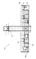
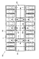
図1は本発明の平面往復方式駐車装置の全体正面図であり、図2は図1の平面図である。図1及び図2に示すように、本発明の平面往復方式駐車装置10は、昇降リフト12、走行台車14、格納棚16及び補助リフト20を備える。
【0019】
昇降リフト12は、入庫高さHから車1を格納する複数の格納高さLまで昇降路内を昇降する。この例では、入庫高さHは地上に位置し、格納高さLは地下にL1、L2の2段に構成されている。昇降機構は、ワイヤで吊り下げて昇降させる通常の機構が好ましいが、これに限定されず周知の機構を適用することができる。
【0020】
走行台車14は、各格納高さLにおいて車1を積載して走行路を水平に走行する。この例では、2段の格納高さL1、L2のそれぞれに複数設けられ、それぞれレール14aの上を車輪で走行するようになっている。
【0021】
複数の格納棚16は、走行台車14の走行方向に沿って、台車に隣接して配置されている。格納棚16は、走行台車14の走行方向に沿って、両側に設けるのが好ましいが、片側のみでもよい。
またこの例で、複数の格納棚16は、車を長手方向に格納する横列配置であり、格納状態において、隣接する車両が幅方向に間隔を隔てて位置する。
【0022】
図2に示すように、昇降リフト12の昇降路と走行台車14の走行路は、走行路の中間位置で交叉する。またこの交叉位置で走行台車14が昇降リフト12上にそのまま走行して載り、昇降リフト12上に走行台車14を搭載するようになっている。
また、昇降リフト12と走行台車14はそれぞれ独立した給電ライン(図示せず)を有する。この給電ラインは昇降リフト12上に走行台車14が位置するときは、走行台車14にも給電するようになっている。
【0023】
補助リフト20は、走行路の両端部にそれぞれ設けられ、独立して運転される。補助リフト20は、それぞれ複数の格納高さL1、L2の間を昇降し、その上に載せた走行台車14を昇降させるようになっている。なお、格納高さは、L1、L2の2段に限定されず、3段以上でもよい。
【0024】
また、昇降路と走行路の交叉位置には、可動レール装置22が設けられ、昇降リフト12が交叉位置に位置しないときに、走行台車14を通過可能に支持するようになっている。この可動レール装置22は例えば部分レールを水平に伸縮させる機構であり、昇降リフト12が交叉位置に位置するときには、部分レールを退避させ、昇降リフト12との干渉を防止するようになっている。
【0025】
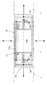
図3は、図1の走行台車14を載せた昇降リフト12の平面図であり、図4は図1の走行台車14のみの平面図である。図3及び図4に示すように、走行台車14は車1を長手方向に移載する縦移載装置15を備える。
【0026】
また図4に示すように、縦移載装置15は、チェーン直動機構17と1対のトンボ機構18からなる。
【0027】
チェーン直動機構17は、長手方向に水平に移動するエンドレスチェーン17aと、これに取り付けられた水平移動ドグ(図示せず)からなり、水平移動ドグがパレット7に設けられた係合部と係合することによりパレット7を車の長手方向に水平移動するようになっている。停止位置は、リミットスイッチ、ストッパ等で位置決めするのがよい。
【0028】
1対のトンボ機構18は、走行台車14の長手方向両端部に設けられている。このトンボ機構18は、水平旋回する水平アーム18aを有し、その先端部の旋回ドクでパレット下部のガイド板を押して車1を載せたパレット7を隣接する格納棚16に移載するようになっている。
【0029】
この構成により、チェーン直動機構17の水平移動するエンドレスチェーン17aにより、長手方向に長いパレット7を、長手方向に水平移動してパレットの大部分を格納棚上に移載し、次いでトンボ機構18の水平旋回する水平アーム18aにより、パレットの末端部を隣接する格納棚上に完全に移載することができる。
【0030】
図5は、図1の昇降リフトの構成図であり、(A)は平面図、(B)は側面図である。この例では昇降リフト12のフレームの4隅に鉛直はガイドが設けられ、このガイドに沿って常に水平を保持しながら昇降するようになっている。
【0031】
図4に示すように、走行台車14はその中央部に後述するパレット支持台13aが通過可能な中央開口14aを有する。また、昇降リフト12は、走行台車14の中央開口14aを通して走行台車上の車を水平旋回させるターンテーブル装置13を備える。
【0032】
図5に示すように、ターンテーブル装置13は、パレット7を支持するパレット支持台13aと、昇降機構13bと旋回機構13cとからなる。
【0033】
パレット支持台13aは、(A)にH型で示す水平部材であり、上昇時にその一部がパレット7を直接支持する。昇降機構13bは、この例では鉛直な4組のボールネジ機構かたなり、図示しない駆動装置でボールネジを同期させて回転し、パレット支持台13aを支持する支持部材を昇降させ、パレット支持台13aを走行台車の中央開口14aを通して昇降させる。旋回機構13cは、パレット支持台13aに固定された水平歯車と噛合し図示しない駆動装置で上昇位置でパレット支持台を水平旋回させるようになっている。
【0034】
この構成により、昇降機構13bでパレット支持台13aを走行台車の中央開口を通して昇降させ、その上昇位置で旋回機構13cによりパレット支持台13aを水平旋回させて、車を水平旋回させることができる。
【0035】
上述した本発明の構成によれば、昇降リフト12の昇降路と走行台車14の走行路が交叉し、その交叉位置で昇降リフト12上に走行台車14を搭載可能になっているので、車を横列に格納した場合でも、正方形に近い矩形敷地に効率よく設置でき、矩形敷地から張り出した特別な昇降スペースを必要とせず、矩形敷地の有効活用が可能となる。
【0036】
また、ある階でリフトが停止しリフト上の走行台車が走行を開始した直後に、逆側から別の台車をリフト上に搭載でき、リフトの待時間を大幅に短縮することができる。
【0037】
更に、走行路の両端部に補助リフト20を備え、複数の格納高さ間で走行台車14を昇降するので、同一階からの入出庫を連続的に行う場合でも、所定の車1又は空パレットを搭載した複数の走行台車14を順次待機させることができ、連続出庫、連続入庫におけるリフトの待時間を大幅に短縮することができ、円滑性を大幅に高めることができる。
【0038】
また従来の平面往復方式駐車装置において、昇降リフト12を格納棚16の位置に移動して矩形敷地からの張り出しを無くした場合と比較しても、本発明では走行台車14の両側全体に格納棚16を配置できるので、その分車の収容台数を増やすことができる。
【0039】
また、格納棚16が、車を長手方向に格納する横列配置であり、走行台車14が車を長手方向に移載する縦移載装置15を備えるので、縦移載装置15により、走行台車14から車を長手方向に複数の格納棚16に移載することができ、車を横列に格納して正方形に近い矩形敷地に効率よく設置できる。
【0040】
なお、本発明は上述した実施形態に限定されず、本発明の要旨を逸脱しない範囲で種々変更できることは勿論である。例えば、上記実施形態では、地下駐車設備の場合を詳述したが、地上の駐車設備にも同様に適用することができる。
【0041】
【発明の効果】
上述したように、本発明の平面往復方式駐車装置は、(1)車を横列に格納して正方形に近い矩形敷地に効率よく設置でき、(2)矩形敷地から張り出した特別な昇降スペースを必要とせず、矩形敷地の有効活用が可能となり、(3)同一階からの入出庫を連続的に行う場合でも、同一階におけるリフトの待時間を短縮し、円滑性を高めることができる等の優れた効果を有する。
【図面の簡単な説明】
【図1】本発明の平面往復方式駐車装置の全体正面図である。
【図2】図1の平面図である。
【図3】図1の走行台車を載せた昇降リフトの平面図である。
【図4】図1の走行台車のみの平面図である。
【図5】図1の昇降リフトの構成図である。
【図6】従来の平面往復方式駐車装置の全体斜視図である。
【符号の説明】
1 車、2a 入庫バース、2b 出庫バース、
3a 入庫リフト、3b 出庫リフト、
4 平面往復台車、5 格納棚、7 パレット、
10 平面往復方式駐車装置、12 昇降リフト、
13 ターンテーブル装置、13a パレット支持台、
13b 昇降機構、13c 旋回機構、
14 走行台車、14a 中央開口、
15 縦移載装置、16 格納棚、
17 チェーン直動機構、17a エンドレスチェーン、
18 トンボ機構、18a 水平アーム、
20 補助リフト、22 可動レール装置[0001]
[Industrial application fields]
The present invention relates to a mechanical parking apparatus, and more particularly to a plane reciprocating parking apparatus.
[0002]
[Prior art]
As a large-scale parking device that efficiently uses the underground space, a flat-return parking device has already been developed. In this plane reciprocating parking device, as schematically shown in FIG. 6, the car 1 is put on the
[0003]
[Problems to be solved by the invention]
The conventional plane reciprocating parking device described above is particularly suitable for a large-scale parking device that uses an underground space. However, when this device is applied to a small and medium-sized parking device, there are the following problems.
[0004]
(1) The occupied space of the
(2) A lifting space for the
[0005]
(3) When carrying in / out from the same floor continuously, the waiting time for the lift on the same floor becomes longer, so the smoothness decreases.
That is, after the lift stops on a certain floor, (a) the car 1 is transferred to the plane reciprocating carriage 4, the carriage 4 runs horizontally and stops in front of a
[0006]
The present invention has been made to solve such problems. That is, the objects of the present invention are as follows: (1) The cars can be stored in rows and installed efficiently on a rectangular site close to a square, and (2) no special lifting space protruding from the rectangular site is required, and the rectangular site is effective. (3) To provide a planar reciprocating parking system that can reduce the waiting time for lifts on the same floor and improve smoothness even when entering and exiting from the same floor continuously. is there.
[0007]
[Means for Solving the Problems]
According to the present invention, the lift lift (12) that moves up and down in the hoistway from the storage height H to a plurality of storage heights L for storing the vehicle, and the vehicle is loaded horizontally at each storage height L to level the travel path. In a planar reciprocating parking apparatus comprising a traveling cart (14) traveling in a straight line and a plurality of storage shelves (16) arranged adjacent to the cart, the hoistway and the traveling path cross at an intermediate position of the traveling path. The traveling carriage (14) can be mounted on the lifting lift (12) at the crossover position, and the traveling carriage (14) is lifted and lowered between a plurality of storage heights provided at both ends of the traveling path. An auxiliary lift (20) that has a central opening (14a) at a central portion thereof, and the lifting lift (12) allows the vehicle on the traveling carriage to pass through the central opening of the traveling carriage. a turntable device for horizontally pivoting comprises (13), this Planar reciprocating type parking apparatus according to claim is provided.
[0008]
According to the configuration of the present invention, the hoistway of the lifting lift (12) and the traveling path of the traveling carriage (14) intersect at an intermediate position of the traveling path, and the traveling carriage (14 on the lifting lift (12) at the intersection position. ) Can be installed efficiently on a rectangular site close to a square even when cars are stored in a row, and there is no need for a special lifting space protruding from the rectangular site. It becomes possible.
[0009]
Further, immediately after the lift stops on a certain floor and the traveling carriage on the lift starts traveling, another carriage can be mounted on the lift from the opposite side, and the waiting time of the lift can be greatly shortened.
[0010]
Further, auxiliary lifts (20) are provided at both ends of the traveling path, and the traveling carriage (14) is moved up and down between a plurality of storage heights. Therefore, even when entering and exiting from the same floor continuously, a predetermined vehicle 1 or a plurality of traveling carriages (14) loaded with empty pallets can be sequentially waited, the waiting time for lift in continuous delivery and continuous entry can be greatly reduced, and smoothness can be greatly improved. .
Moreover, even when entering / exiting with one lift / lower lift (12), the turntable device (13) can turn the vehicle on the traveling carriage horizontally at the entry / exit section, and the entry / The advance warehouse can be realized.
[0011]
According to a preferred embodiment of the present invention, there is provided a movable rail device (22) that supports the traveling carriage (14) so that it can pass when the lifting lift (12) is not located at the crossing position of the hoistway and the traveling path. .
[0012]
With this configuration, since the traveling carriage (14) can pass through the crossing position of the hoistway and the traveling path by the movable rail device (22), the traveling carriage (14) can travel freely even while the elevating lift (12) is elevated, It is possible to efficiently prepare for loading and unloading.
[0017]
DETAILED DESCRIPTION OF THE INVENTION
Hereinafter, preferred embodiments of the present invention will be described with reference to the drawings. In each figure, common portions are denoted by the same reference numerals, and redundant description is omitted.
[0018]
FIG. 1 is an overall front view of the flat reciprocating parking apparatus of the present invention, and FIG. 2 is a plan view of FIG. As shown in FIGS. 1 and 2, the planar reciprocating
[0019]
The
[0020]
The traveling
[0021]
The plurality of
Further, in this example, the plurality of
[0022]
As shown in FIG. 2, the hoistway of the lifting
Further, the lifting
[0023]
The auxiliary lifts 20 are provided at both ends of the travel path and are operated independently. The
[0024]
In addition, a
[0025]
FIG. 3 is a plan view of the lifting
[0026]
As shown in FIG. 4, the
[0027]
The chain
[0028]
The pair of
[0029]
With this configuration, the
[0030]
FIG. 5 is a configuration diagram of the lifting lift of FIG. 1, (A) is a plan view, and (B) is a side view. In this example, vertical guides are provided at the four corners of the frame of the
[0031]
As shown in FIG. 4, the traveling
[0032]
As shown in FIG. 5, the
[0033]
The
[0034]
With this configuration, the
[0035]
According to the configuration of the present invention described above, the hoistway of the lifting
[0036]
Further, immediately after the lift stops on a certain floor and the traveling carriage on the lift starts traveling, another carriage can be mounted on the lift from the opposite side, and the waiting time of the lift can be greatly shortened.
[0037]
Furthermore, since the
[0038]
Further, in the conventional plane reciprocating parking device, the present invention also has storage shelves on both sides of the traveling
[0039]
Further, the
[0040]
In addition, this invention is not limited to embodiment mentioned above, Of course, it can change variously in the range which does not deviate from the summary of this invention. For example, in the above-described embodiment, the case of an underground parking facility has been described in detail, but the present invention can be similarly applied to an above-ground parking facility.
[0041]
【The invention's effect】
As described above, the plane reciprocating parking system of the present invention (1) can store cars in a row and can be efficiently installed on a rectangular site near a square, and (2) requires a special lifting space protruding from the rectangular site. It is possible to effectively use the rectangular site, and (3) even when performing continuous loading and unloading from the same floor, it is possible to shorten the lift waiting time on the same floor and improve smoothness. It has the effect.
[Brief description of the drawings]
FIG. 1 is an overall front view of a flat reciprocating parking apparatus according to the present invention.
2 is a plan view of FIG. 1. FIG.
3 is a plan view of an elevating lift on which the traveling carriage shown in FIG. 1 is mounted. FIG.
4 is a plan view of only the traveling carriage of FIG. 1. FIG.
FIG. 5 is a configuration diagram of the lifting lift of FIG. 1;
FIG. 6 is an overall perspective view of a conventional planar reciprocating parking device.
[Explanation of symbols]
1 car, 2a incoming berth, 2b outgoing berth,
3a Entry lift, 3b Delivery lift,
4 flat carriages, 5 storage shelves, 7 pallets,
10 plane reciprocating parking system, 12 lift lift,
13 turntable device, 13a pallet support,
13b lifting mechanism, 13c turning mechanism,
14 traveling cart, 14a center opening,
15 vertical transfer device, 16 storage shelf,
17 Chain linear motion mechanism, 17a Endless chain,
18 dragonfly mechanism, 18a horizontal arm,
20 Auxiliary lift, 22 Movable rail device
Claims (2)
前記走行台車(14)は中央部に中央開口(14a)を有し、前記昇降リフト(12)は、前記走行台車の中央開口を通して前記走行台車上の車を水平旋回させるターンテーブル装置(13)を備える、ことを特徴とする平面往復方式駐車装置。A lifting lift (12) that moves up and down in the hoistway from a storage height H to a plurality of storage heights L for storing the vehicle, and a traveling carriage that loads the vehicle at each storage height L and travels horizontally on the traveling path ( 14) and a plane reciprocating parking device comprising a plurality of storage shelves (16) arranged adjacent to the carriage, wherein the hoistway and the traveling path cross at an intermediate position of the traveling path, The traveling carriage (14) can be mounted on the lifting lift (12), and the auxiliary lift (20) is provided at both ends of the traveling path and lifts the traveling carriage (14) between a plurality of storage heights. With
The traveling carriage (14) has a central opening (14a) at the center, and the lift (12) is a turntable device (13) for horizontally turning the vehicle on the traveling carriage through the central opening of the traveling carriage. A plane reciprocating parking device characterized by comprising:
Priority Applications (1)
| Application Number | Priority Date | Filing Date | Title |
|---|---|---|---|
| JP2002153423A JP4032380B2 (en) | 2002-05-28 | 2002-05-28 | Flat reciprocating parking system |
Applications Claiming Priority (1)
| Application Number | Priority Date | Filing Date | Title |
|---|---|---|---|
| JP2002153423A JP4032380B2 (en) | 2002-05-28 | 2002-05-28 | Flat reciprocating parking system |
Publications (3)
| Publication Number | Publication Date |
|---|---|
| JP2003343109A JP2003343109A (en) | 2003-12-03 |
| JP2003343109A5 JP2003343109A5 (en) | 2005-07-21 |
| JP4032380B2 true JP4032380B2 (en) | 2008-01-16 |
Family
ID=29770464
Family Applications (1)
| Application Number | Title | Priority Date | Filing Date |
|---|---|---|---|
| JP2002153423A Expired - Fee Related JP4032380B2 (en) | 2002-05-28 | 2002-05-28 | Flat reciprocating parking system |
Country Status (1)
| Country | Link |
|---|---|
| JP (1) | JP4032380B2 (en) |
Families Citing this family (1)
| Publication number | Priority date | Publication date | Assignee | Title |
|---|---|---|---|---|
| JP7037947B2 (en) * | 2018-01-31 | 2022-03-17 | Ihi運搬機械株式会社 | How to repair a flat reciprocating parking device |
-
2002
- 2002-05-28 JP JP2002153423A patent/JP4032380B2/en not_active Expired - Fee Related
Also Published As
| Publication number | Publication date |
|---|---|
| JP2003343109A (en) | 2003-12-03 |
Similar Documents
| Publication | Publication Date | Title |
|---|---|---|
| KR100452858B1 (en) | Palletless rack type car parking system with staker crane | |
| JP2006521260A (en) | Multi-trolley type container crane | |
| JPH06293404A (en) | Shelf equipment with transfer device | |
| JP2000118630A (en) | Automatic storage and retrieval system | |
| JP4032380B2 (en) | Flat reciprocating parking system | |
| JP4215140B2 (en) | Stacking puzzle parking equipment | |
| JP3969710B2 (en) | Flat reciprocating parking system | |
| JP2003328582A (en) | Plane reciprocation system parking device | |
| JPH05106359A (en) | Elevator type multistory parking device | |
| JPH084345A (en) | Mechanical type parking tower garage | |
| JP3503668B2 (en) | Mechanical parking device | |
| JP3024222U (en) | Pallet type storage system | |
| JP2612479B2 (en) | Recirculating parking facilities | |
| JP2000264406A (en) | Automatic warehouse with bridging function | |
| CN218623585U (en) | Vehicle carrying device and stereo garage | |
| JP7289209B2 (en) | mechanical parking device | |
| JP2003343110A (en) | Plane reciprocating parking system | |
| JP2880115B2 (en) | Mechanical parking lot | |
| JP2551470B2 (en) | Elevator type parking system | |
| JP4212449B2 (en) | Mechanical parking equipment and driving method thereof | |
| JP3748659B2 (en) | Vertical lift parking device | |
| JP2000328808A (en) | Plane reciprocation type parking device | |
| JP3104051B2 (en) | Multi-stage parking device | |
| JPH11350771A (en) | Multistory parking space | |
| JP2003343109A5 (en) |
Legal Events
| Date | Code | Title | Description |
|---|---|---|---|
| A521 | Written amendment |
Free format text: JAPANESE INTERMEDIATE CODE: A523 Effective date: 20041209 |
|
| A621 | Written request for application examination |
Free format text: JAPANESE INTERMEDIATE CODE: A621 Effective date: 20041209 |
|
| A711 | Notification of change in applicant |
Free format text: JAPANESE INTERMEDIATE CODE: A711 Effective date: 20050929 |
|
| RD05 | Notification of revocation of power of attorney |
Free format text: JAPANESE INTERMEDIATE CODE: A7425 Effective date: 20051209 |
|
| A131 | Notification of reasons for refusal |
Free format text: JAPANESE INTERMEDIATE CODE: A131 Effective date: 20070219 |
|
| A521 | Written amendment |
Free format text: JAPANESE INTERMEDIATE CODE: A523 Effective date: 20070405 |
|
| A131 | Notification of reasons for refusal |
Free format text: JAPANESE INTERMEDIATE CODE: A131 Effective date: 20070606 |
|
| A521 | Written amendment |
Free format text: JAPANESE INTERMEDIATE CODE: A523 Effective date: 20070720 |
|
| TRDD | Decision of grant or rejection written | ||
| A01 | Written decision to grant a patent or to grant a registration (utility model) |
Free format text: JAPANESE INTERMEDIATE CODE: A01 Effective date: 20071012 |
|
| A61 | First payment of annual fees (during grant procedure) |
Free format text: JAPANESE INTERMEDIATE CODE: A61 Effective date: 20071012 |
|
| FPAY | Renewal fee payment (event date is renewal date of database) |
Free format text: PAYMENT UNTIL: 20101102 Year of fee payment: 3 |
|
| R150 | Certificate of patent or registration of utility model |
Ref document number: 4032380 Country of ref document: JP Free format text: JAPANESE INTERMEDIATE CODE: R150 Free format text: JAPANESE INTERMEDIATE CODE: R150 |
|
| FPAY | Renewal fee payment (event date is renewal date of database) |
Free format text: PAYMENT UNTIL: 20101102 Year of fee payment: 3 |
|
| S533 | Written request for registration of change of name |
Free format text: JAPANESE INTERMEDIATE CODE: R313533 |
|
| FPAY | Renewal fee payment (event date is renewal date of database) |
Free format text: PAYMENT UNTIL: 20101102 Year of fee payment: 3 |
|
| R350 | Written notification of registration of transfer |
Free format text: JAPANESE INTERMEDIATE CODE: R350 |
|
| S531 | Written request for registration of change of domicile |
Free format text: JAPANESE INTERMEDIATE CODE: R313531 |
|
| FPAY | Renewal fee payment (event date is renewal date of database) |
Free format text: PAYMENT UNTIL: 20101102 Year of fee payment: 3 |
|
| R350 | Written notification of registration of transfer |
Free format text: JAPANESE INTERMEDIATE CODE: R350 |
|
| FPAY | Renewal fee payment (event date is renewal date of database) |
Free format text: PAYMENT UNTIL: 20111102 Year of fee payment: 4 |
|
| R250 | Receipt of annual fees |
Free format text: JAPANESE INTERMEDIATE CODE: R250 |
|
| FPAY | Renewal fee payment (event date is renewal date of database) |
Free format text: PAYMENT UNTIL: 20121102 Year of fee payment: 5 |
|
| R250 | Receipt of annual fees |
Free format text: JAPANESE INTERMEDIATE CODE: R250 |
|
| FPAY | Renewal fee payment (event date is renewal date of database) |
Free format text: PAYMENT UNTIL: 20121102 Year of fee payment: 5 |
|
| FPAY | Renewal fee payment (event date is renewal date of database) |
Free format text: PAYMENT UNTIL: 20131102 Year of fee payment: 6 |
|
| R250 | Receipt of annual fees |
Free format text: JAPANESE INTERMEDIATE CODE: R250 |
|
| R250 | Receipt of annual fees |
Free format text: JAPANESE INTERMEDIATE CODE: R250 |
|
| R250 | Receipt of annual fees |
Free format text: JAPANESE INTERMEDIATE CODE: R250 |
|
| R250 | Receipt of annual fees |
Free format text: JAPANESE INTERMEDIATE CODE: R250 |
|
| R250 | Receipt of annual fees |
Free format text: JAPANESE INTERMEDIATE CODE: R250 |
|
| R250 | Receipt of annual fees |
Free format text: JAPANESE INTERMEDIATE CODE: R250 |
|
| LAPS | Cancellation because of no payment of annual fees |