JP4032059B2 - Double pipe double packer method - Google Patents
Double pipe double packer method Download PDFInfo
- Publication number
- JP4032059B2 JP4032059B2 JP2005091543A JP2005091543A JP4032059B2 JP 4032059 B2 JP4032059 B2 JP 4032059B2 JP 2005091543 A JP2005091543 A JP 2005091543A JP 2005091543 A JP2005091543 A JP 2005091543A JP 4032059 B2 JP4032059 B2 JP 4032059B2
- Authority
- JP
- Japan
- Prior art keywords
- pipe
- casing
- injection
- double
- natural ground
- Prior art date
- Legal status (The legal status is an assumption and is not a legal conclusion. Google has not performed a legal analysis and makes no representation as to the accuracy of the status listed.)
- Expired - Fee Related
Links
Images


Description
本発明は、地山に設置され、吐出孔が形成された中空のスリーブパイプ内に、噴出孔が形成された中空のインジェクションパイプを挿入し、該インジェクションパイプの後端から注入材を供給して、該注入材を前記噴出孔及び吐出孔を介して地山に注入する二重管ダブルパッカー工法に関する。 The present invention inserts a hollow injection pipe formed with an ejection hole into a hollow sleeve pipe installed in a natural ground and formed with a discharge hole, and supplies an injection material from the rear end of the injection pipe. The present invention relates to a double-pipe double packer method for injecting the injection material into the natural ground through the ejection holes and the discharge holes.
従来より、二重管ダブルパッカー工法における地山への削孔は、二重管掘削によって行われていた。この二重管掘削とは、まず、ケーシング及びインナーロッドの後端を二重管掘削機のスイベルに接続して、インナーロッドの先端から切削水を噴射するとともにケーシングとインナーロッドとの間隙より泥水を排水しながら、ケーシング及びインナーロッドの先端のビットに二重管掘削機による打撃力と回転力とを伝達することによって削孔を行う。その後、インナーロッドを引き抜き、ケーシング内に中空のスリーブパイプを建て込んだ後、ケーシングを引き抜き、スリーブパイプ内に噴出孔を備えた中空のインジェクションパイプを挿入して、注入材を地山に注入するものである。よって、二重管掘削機のスイベルは、打撃力及び回転力をケーシング及びインナーロッドに伝達してそれぞれを引き抜くことができ、切削水及び泥水の流路と、これらの切削水及び泥水が漏れないようにパッカー機能とを備えている必要がある(特許文献1参照)。
一方、NATM(New Austrian Tunnelling Method)やTBM(Tunnel Boring Machine)工法等によるトンネル掘削現場では、二重管掘削機は常備されておらず、単管掘削機が常備されていることが多い。しかし、この単管掘削機にはスイベルが備えられていないため、インナーロッドとともにケーシングを地山に打ち込んでも、地山からケーシングを引き抜くことができない。よって、これらの現場で二重管ダブルパッカー工法を採用するには二重管掘削機を準備せねばならず、この二重管掘削機の準備やトンネル掘削現場への搬送に時間を要し、工期が長引く問題があった。 On the other hand, in a tunnel excavation site by a NATM (New Australian Tunneling Method) or TBM (Tunnel Boring Machine) method, a double-pipe excavator is not always provided, and a single-pipe excavator is often provided. However, since this single pipe excavator is not provided with a swivel, even if the casing is driven into the natural ground together with the inner rod, the casing cannot be pulled out from the natural ground. Therefore, in order to adopt the double pipe double packer construction method at these sites, it is necessary to prepare a double pipe excavator, and it takes time to prepare this double pipe excavator and transport it to the tunnel excavation site, There was a problem that the construction period was prolonged.
本発明の課題は、工期を遅延させずに二重管ダブルパッカー工法を行うことである。 An object of the present invention is to perform a double pipe double packer method without delaying the construction period.
以上の課題を解決するため、請求項1に記載の発明は、例えば図1及び2に示すように、周壁に複数の注入孔1aを設け、かつリングビット1bを先端に取り付けたケーシング1内に、単管掘削が可能な単管掘削機(図示せず)から受けた打撃力及び回転力を前記リングビット1bに伝える掘削ビット2aを取り付けたインナーロッド2を挿入し、
前記単管掘削機に連結した前記インナーロッド2と、前記ケーシング1とによって地山Gに削孔を行い、前記ケーシング1から前記インナーロッド2及び掘削ビット2aを引き抜いた後、
吐出孔3aが形成されたパイプ(例えば、スリーブパイプ3)を前記ケーシング1内に挿入するとともに、前記パイプ(例えば、スリーブパイプ3)の先端に、その径方向外側に開いて前記ケーシング1の内壁に当接する複数の羽部材3cを設けることによって前記ケーシング1の中心位置に配置し、さらに前記ケーシング1と前記パイプ(例えば、スリーブパイプ3)との間隙にシール材6を充填し、
前記パイプ(例えば、スリーブパイプ3)内に、該パイプ(例えば、スリーブパイプ3)内の空間を隔てる一対のパッカー4b,4bと、これらのパッカー4b,4bの間に設けられた噴出孔4aと、を備えるインジェクションパイプ4を挿入し、
前記ケーシング1を地山G内に設置した状態で、前記インジェクションパイプ4の後端から注入材5を供給し、該注入材5を前記噴出孔4a及び吐出孔3aを介して前記注入孔1aから地山に注入し、
前記インジェクションパイプ4を引き抜いた後、前記ケーシング1およびパイプ(例えば、スリーブパイプ3)を地山G内に残置しておくことを特徴としている。
In order to solve the above-mentioned problems, the invention described in claim 1 includes, as shown in FIGS. 1 and 2, for example, a casing 1 in which a plurality of
After drilling holes in the natural ground G by the inner rod 2 connected to the single pipe excavator and the casing 1, and pulling out the inner rod 2 and the
A pipe (for example, a sleeve pipe 3) in which a
In the pipe (for example, the sleeve pipe 3), a pair of
In a state where the casing 1 is installed in the natural ground G, the
After the injection pipe 4 is pulled out, the casing 1 and the pipe (for example, the sleeve pipe 3) are left in the natural ground G.
請求項1に記載の発明によれば、単管掘削機にインナーロッドを連結して打撃力及び回転力を与えると、この打撃力及び回転力が、インナーロッドの先端に取り付けられた掘削ビットを介してケーシングに取り付けられたリングビットに伝達される。よって、単管掘削機を用いて、ケーシングと、このケーシング内に挿入されたインナーロッドとによって地山に削孔を行うことができる。削孔後、インナーロッドを引き抜き、ケーシング内にパイプを挿入するとともにケーシングとパイプとの間隙にシール材を充填し、パイプ内にインジェクションパイプを挿入して、このインジェクションパイプの後端から注入材を供給する。これにより、注入材はインジェクションパイプの噴出孔を介して、パイプ内と一対のパッカーとで形成された空間に充填される。その後、注入材は、パイプの吐出孔を介して、ケーシングとパイプとの間隙に充填されたシール材の中を流れ、ケーシングの注入孔を介して地山に注入されて地山が補強される。よって、ケーシングを引き抜く作業を省略することができるため、二重管掘削機がない現場においても、単管掘削機によって二重管ダブルパッカー工法を行うことができ、二重管掘削機を準備及び搬送する必要はなく、工期の遅延を防ぐことができる。また、注入材を地山に注入した後もケーシングは地山内に残置されるため、ケーシングによって、地山の変形を抑制することができる。 According to the first aspect of the present invention, when the inner rod is connected to the single pipe excavator to give a striking force and a rotational force, the striking force and the rotational force are applied to the excavation bit attached to the tip of the inner rod. To the ring bit attached to the casing. Therefore, a single pipe excavator can be used to drill holes in the natural ground by the casing and the inner rod inserted into the casing. After drilling, the inner rod is pulled out, the pipe is inserted into the casing, the gap between the casing and the pipe is filled with a sealing material, the injection pipe is inserted into the pipe, and the injection material is injected from the rear end of the injection pipe. Supply. Thereby, the injection material is filled into the space formed by the pipe and the pair of packers through the injection hole of the injection pipe. After that, the injection material flows through the seal hole filled in the gap between the casing and the pipe through the discharge hole of the pipe, and is injected into the natural ground through the injection hole of the casing to reinforce the natural ground. . Therefore, since the work of pulling out the casing can be omitted, the double pipe double packer method can be performed by the single pipe excavator even in a site where there is no double pipe excavator. There is no need to carry it, and the construction period can be prevented from being delayed. Moreover, since a casing is left in a natural ground even after inject | pouring an injection material into a natural ground, a deformation | transformation of a natural ground can be suppressed with a casing.
請求項2に記載の発明は、請求項1に記載の二重管ダブルパッカー工法において、前記単管掘削機は、地質探査用の先進ボーリングマシンであることを特徴としている。 The invention according to claim 2 is the double pipe double packer method according to claim 1, wherein the single pipe excavator is an advanced boring machine for geological exploration.
請求項2に記載の発明によれば、単管掘削機は地質探査用の先進ボーリングマシンであるため、ケーシング及びインナーロッドによって、地山に削孔を確実に行うことができる。 According to the second aspect of the present invention, since the single pipe excavator is an advanced boring machine for geological exploration, it is possible to reliably drill holes in the natural ground by the casing and the inner rod.
請求項3に記載の発明は、請求項1に記載の二重管ダブルパッカー工法において、前記単管掘削機は、ドリルジャンボであることを特徴としている。
The invention described in
請求項3に記載の発明によれば、単管掘削機はドリルジャンボであるため、ケーシング及びインナーロッドによって、地山に削孔を確実に行うことができる上、ドリルジャンボは複数のドリフタを備えているため、同時に複数の削孔を行うことができる。 According to the third aspect of the present invention, since the single-pipe excavator is a drill jumbo, a drill hole can be reliably drilled in the natural ground by the casing and the inner rod, and the drill jumbo includes a plurality of drifters. Therefore, a plurality of drilling holes can be performed at the same time.
本発明によれば、ケーシングを引き抜く作業を省略することができるため、二重管掘削機がない現場においても、単管掘削機によって二重管ダブルパッカー工法を行うことができ、二重管掘削機を準備及び搬送する必要はなく、工期の遅延を防ぐことができる。また、注入材を地山に注入した後もケーシングは地山内に残置されるため、ケーシングによって、地山の変形を抑制することができる。 According to the present invention, since the operation of pulling out the casing can be omitted, the double-pipe double packer method can be performed by the single-pipe excavator even in a site where there is no double-pipe excavator. It is not necessary to prepare and transport the machine, and the construction period can be prevented from being delayed. Moreover, since a casing is left in a natural ground even after inject | pouring an injection material into a natural ground, a deformation | transformation of a natural ground can be suppressed with a casing.
以下、図を参照して本発明を実施するための実施形態を詳細に説明する。
図1は、TBM工法によるトンネル掘削現場において、二重管ダブルパッカー工法によって掘削方向の地山Gを補強するために、地山G内にケーシング1を設置したものである。図2は、ケーシング1及びインナーロッド2による削孔を示すものである。図3は、二重管ダブルパッカー工法の施工手順を示すものである。
DESCRIPTION OF EMBODIMENTS Hereinafter, embodiments for carrying out the present invention will be described in detail with reference to the drawings.
FIG. 1 shows a case where a casing 1 is installed in a natural ground G in order to reinforce the natural ground G in the excavation direction by a double pipe double packer construction method at a tunnel excavation site by the TBM method. FIG. 2 shows drilling by the casing 1 and the inner rod 2. FIG. 3 shows the construction procedure of the double pipe double packer method.
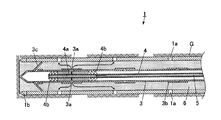
図1及び2に示すように、地山G内に設置されたケーシング1の周壁には、複数の注入孔1aが設けられている。このケーシング1は、先端にリングビット1bが接合されており、このリングビット1bに打撃力及び回転力を伝達する掘削ビット2aを取り付けたインナーロッド2をケーシング1内に挿入した状態で、削孔を行う。
As shown in FIGS. 1 and 2, a plurality of
ケーシング1内には、中空のスリーブパイプ3が挿入されている。このスリーブパイプ3には、所定間隔に筒状体のゴム製のスリーブ3bが嵌められており、スリーブパイプ3及びスリーブ3bには、注入材5の流路としての微小の吐出孔3aが形成されている。このスリーブパイプ3の内側の注入材5に圧力をかけることによって、注入材5は吐出孔3aを押し広げて勢い良くスリーブパイプ3の外へと噴出す。また、スリーブパイプ3の先端には、その径方向外側に開いた複数の棒状の羽部材3cが設けられている。この羽部材3cは、先端がケーシング1の内壁に当接しており、スリーブパイプ3をケーシング1の中心位置に配置させるためのものである。
A
スリーブパイプ3内には、中空のインジェクションパイプ4が挿入されている。このインジェクションパイプ4の先端部には、スリーブパイプ3内の空間をその長軸方向に隔てる一対のパッカー4b,4bが備えられており、インジェクションパイプ4のこれらのパッカー4b,4bの間には、噴出孔4aが形成されている。
A hollow injection pipe 4 is inserted into the
次に、本発明に係る二重管ダブルパッカー工法の施工手順について詳細に説明する。 Next, the construction procedure of the double pipe double packer method according to the present invention will be described in detail.
まず、先端にリングビット1bを備えたケーシング1の中に、先端に掘削ビット2aを備えたインナーロッド2を挿入し、インナーロッド2の後端を地質探査用の先進ボーリングマシンに連結して、地山Gに削孔を行う。詳しくは、インナーロッド2の後端に地質探査用の先進ボーリングマシンから打撃力及び回転力が与えられ、インナーロッド2の先端の掘削ビット2aと、この掘削ビット2aを介して打撃力及び回転力が伝達されるリングビット1bとが、地山Gを掘削する。なお、地質探査用の先進ボーリングマシンは、TBM工法のトンネル掘削現場に常備されるものを用いる。
First, the inner rod 2 with the
ケーシング1及びインナーロッド2で地山Gに所定長さ削孔した後、図3(a)に示すように、インナーロッド2(図2参照)を引き抜いてケーシング1のみを地山G内に残置する。 After a predetermined length is drilled in the natural ground G with the casing 1 and the inner rod 2, the inner rod 2 (see FIG. 2) is pulled out to leave only the casing 1 in the natural ground G as shown in FIG. To do.
次に、図3(b)に示すように、ケーシング1内にスリーブパイプ3を挿入する。このとき、スリーブパイプ3の先端には複数の羽部材3c(図1参照)が設けられているため、スリーブパイプ3はケーシング1の中心位置を維持した状態で挿入される。その後、図3(c)に示すように、ケーシング1の内面とスリーブパイプ3の外面との間隙にシール材6を充填する。
なお、シール材6は、ケーシング1内にスリーブパイプ3を挿入する前に充填してもよい。
Next, as shown in FIG. 3B, the
The sealing material 6 may be filled before the
次に、図3(d)に示すように、スリーブパイプ3内にインジェクションパイプ4を挿入し、スリーブパイプ3の最後端側の吐出孔3aが一対のパッカー4b,4bの間に位置するようにし、インジェクションパイプ4の後端から注入材5を圧入する。
Next, as shown in FIG. 3D, the injection pipe 4 is inserted into the
インジェクションパイプ4の後端から圧入された注入材5は、インジェクションパイプ4内を通り先端側の噴出孔4a(図1参照)を介して、インジェクションパイプ4の外面、スリーブパイプ3の内面、及び一対のパッカー4b,4bによって形成された空間に充填される。その後、注入材5は、スリーブパイプ3の吐出孔3aを押し広げてスリーブパイプ3の外へ噴出し、スリーブパイプ3の外面とケーシング1の内面との間隙に充填されたシール材6の中を流れる。そして、スリーブパイプ3の最後端側の吐出孔3aに近接したケーシング1の注入孔1aを介して地山Gに注入され、地山Gが補強される。
The
ケーシング1の周囲の地山Gに注入材5が適量注入されたら、注入材5の圧入を止め、インジェクションパイプ4を先端方向に所定間隔だけ移動させて、スリーブパイプ3の後端側から2番目の吐出孔3aが一対のパッカー4b,4bの間に位置するようにし、再び注入材5を注入する。
When an appropriate amount of the
その後、注入材5の圧入と、インジェクションパイプ4の先端方向への移動とを繰り返し行い、ケーシング1の周囲の地山Gをケーシング1の後端側から順に補強していく。
Thereafter, the injection of the
なお、注入材5を地山Gに注入する前に、注入材5と同じように圧力水をインジェクションパイプ4の後端から供給することによって、シール材6にクラッキングを行ってもよい。
Before injecting the
地山Gへの注入材5の注入作業が終わったら、インジェクションパイプ4を引き抜き、ケーシング1、スリーブパイプ3はそのまま地山G内に残置しておく。
When the operation of injecting the
以上の実施形態によれば、地質探査用の先進ボーリングマシンにインナーロッド2を連結して打撃力及び回転力を与えると、この打撃力及び回転力が、インナーロッド2の先端に取り付けられた掘削ビット2aを介してケーシング1に取り付けられたリングビット1bに伝達される。よって、地質探査用の先進ボーリングマシンを用いて、ケーシング1と、このケーシング1内に挿入されたインナーロッド2とによって地山Gに確実に削孔をすることができる。掘削後、インナーロッド2を引き抜き、ケーシング1内にスリーブパイプ3を挿入するとともにケーシング1とスリーブパイプ3との間隙にシール材6を充填し、スリーブパイプ3内にインジェクションパイプ4を挿入して、このインジェクションパイプ4の後端から注入材5を圧入する。これにより、注入材5はインジェクションパイプ4の噴出孔4aを介して、スリーブパイプ3内と一対のパッカー4b,4bとで形成された空間に充填される。その後、注入材5は、スリーブパイプ3の吐出孔3aを介して、ケーシング1とスリーブパイプ3との間隙に充填されたシール材4の中を流れ、ケーシング1の注入孔1aを介して地山Gに注入されて地山Gが補強される。よって、ケーシング1を引き抜く作業を省略することができるため、二重管掘削機がない現場においても、地質探査用の先進ボーリングマシンによって二重管ダブルパッカー工法を行うことができ、二重管掘削機を準備及び搬送する必要はなく、工期の遅延を防ぐことができる。また、注入材5を地山Gに注入した後もケーシング1は地山G内に残置されるため、このケーシング1によって、地山Gの変形を抑制することができる。
According to the above embodiment, when the inner rod 2 is connected to the advanced boring machine for geological exploration to give a striking force and a rotational force, the striking force and the rotational force are excavated attached to the tip of the inner rod 2. It is transmitted to the
なお、以上の実施形態においては、地質探査用の先進ボーリングマシンで掘削を行ったが、NATMの現場に常備されるドリルジャンボで行ってもよい。この場合、上記の実施形態で得られた効果の他に、ドリルジャンボは複数のドリフタを備えているため、同時に複数の削孔を行うことができる。 In the above embodiment, excavation is performed with an advanced boring machine for geological exploration, but it may be performed with a drill jumbo that is always provided at the site of NATM. In this case, in addition to the effects obtained in the above embodiment, the drill jumbo includes a plurality of drifters, so that a plurality of holes can be drilled simultaneously.
1 ケーシング
1a 注入孔
1b リングビット
2 インナーロッド
2a 掘削ビット
3 スリーブパイプ
3a 吐出孔
3b スリーブ
4 インジェクションパイプ
4a 噴出孔
4b パッカー
5 注入材
6 シール材
DESCRIPTION OF SYMBOLS 1
Claims (3)
前記単管掘削機に連結した前記インナーロッドと、前記ケーシングとによって地山に削孔を行い、前記ケーシングから前記インナーロッド及び掘削ビットを引き抜いた後、
吐出孔が形成されたパイプを前記ケーシング内に挿入するとともに、前記パイプの先端に、その径方向外側に開いて前記ケーシングの内壁に当接する複数の羽部材を設けることによって前記ケーシングの中心位置に配置し、さらに前記ケーシングと前記パイプとの間隙にシール材を充填し、
前記パイプ内に、該パイプ内の空間を隔てる一対のパッカーと、これらのパッカーの間に設けられた噴出孔と、を備えるインジェクションパイプを挿入し、
前記ケーシングを地山内に設置した状態で、前記インジェクションパイプの後端から注入材を供給し、該注入材を前記噴出孔及び吐出孔を介して前記注入孔から地山に注入し、
前記インジェクションパイプを引き抜いた後、前記ケーシングおよびスリーブパイプを地山内に残置しておくことを特徴とする二重管ダブルパッカー工法。 A drilling bit for transmitting the striking force and rotational force received from a single-pipe excavator capable of single-pipe excavation to the ring bit was installed in a casing provided with a plurality of injection holes in the peripheral wall and attached to the tip of the ring bit. Insert the inner rod,
After drilling a natural ground by the inner rod connected to the single pipe excavator and the casing, after pulling the inner rod and excavation bit from the casing,
A pipe having a discharge hole is inserted into the casing, and a plurality of wing members are provided at the tip of the pipe so as to open radially outward and contact the inner wall of the casing. And further, a seal material is filled in the gap between the casing and the pipe,
Inserting an injection pipe comprising a pair of packers separating the space in the pipe into the pipe and an ejection hole provided between the packers,
In a state where the casing is installed in a natural ground, an injection material is supplied from the rear end of the injection pipe, and the injection material is injected from the injection hole into the natural ground via the ejection hole and the discharge hole,
After the injection pipe is pulled out, the casing and the sleeve pipe are left in the ground.
Priority Applications (1)
| Application Number | Priority Date | Filing Date | Title |
|---|---|---|---|
| JP2005091543A JP4032059B2 (en) | 2005-03-28 | 2005-03-28 | Double pipe double packer method |
Applications Claiming Priority (1)
| Application Number | Priority Date | Filing Date | Title |
|---|---|---|---|
| JP2005091543A JP4032059B2 (en) | 2005-03-28 | 2005-03-28 | Double pipe double packer method |
Publications (2)
| Publication Number | Publication Date |
|---|---|
| JP2006274562A JP2006274562A (en) | 2006-10-12 |
| JP4032059B2 true JP4032059B2 (en) | 2008-01-16 |
Family
ID=37209589
Family Applications (1)
| Application Number | Title | Priority Date | Filing Date |
|---|---|---|---|
| JP2005091543A Expired - Fee Related JP4032059B2 (en) | 2005-03-28 | 2005-03-28 | Double pipe double packer method |
Country Status (1)
| Country | Link |
|---|---|
| JP (1) | JP4032059B2 (en) |
Families Citing this family (1)
| Publication number | Priority date | Publication date | Assignee | Title |
|---|---|---|---|---|
| CN112663883B (en) * | 2020-12-22 | 2022-03-29 | 浙江省建筑设计研究院 | Prefabricated staircase with pore channels and installation method thereof |
-
2005
- 2005-03-28 JP JP2005091543A patent/JP4032059B2/en not_active Expired - Fee Related
Also Published As
| Publication number | Publication date |
|---|---|
| JP2006274562A (en) | 2006-10-12 |
Similar Documents
| Publication | Publication Date | Title |
|---|---|---|
| JP4288331B2 (en) | Rock bolt and supporting method using the same | |
| KR101030686B1 (en) | Simultaneous method using a simultaneous-injecting apparatus comprising packer and u-shape pipe | |
| JP5614774B2 (en) | Chemical injection device | |
| JP5439073B2 (en) | Double pipe drilling tool | |
| JP5401182B2 (en) | How to install inflatable rock bolts | |
| JP3493014B2 (en) | Tunnel widening method | |
| JP4032059B2 (en) | Double pipe double packer method | |
| JP5439320B2 (en) | Construction method of two-way pressurized injection short rock bolt | |
| JP3952266B2 (en) | Double pipe drilling tools | |
| JP4138796B2 (en) | Steel pipe placing method and steel pipe placing tool | |
| JP5384223B2 (en) | How to install pipes on natural ground | |
| JP2007016394A (en) | Pipe installing construction method and hole drilling device | |
| JP3851590B2 (en) | Preceding ground mountain consolidation method using self-drilling bolt and FRP bolt | |
| JPH11200750A (en) | Excavation bit for winding hole and execution method using it | |
| JP2007231733A (en) | Double pipe type excavating tool | |
| JP2000204899A (en) | Self-drilling anchor | |
| JP6521311B2 (en) | Chemical solution injection method under pressurized water | |
| JP7311894B2 (en) | Ground reinforcement method | |
| JP4310281B2 (en) | Self-drilling bolt and its construction method | |
| JP2000328560A (en) | Method of creating steel pipe column row earth retaining wall | |
| JP4349522B2 (en) | Ground improvement method | |
| JP2002285778A (en) | Excavator | |
| JP4714927B2 (en) | Tunnel excavation method and mirror set bolt | |
| JPH11217991A (en) | Drift excavation device | |
| JP2006124957A (en) | Excavating bit for construction of anchor, and construction method for anchor, using it |
Legal Events
| Date | Code | Title | Description |
|---|---|---|---|
| A977 | Report on retrieval |
Free format text: JAPANESE INTERMEDIATE CODE: A971007 Effective date: 20070216 |
|
| A131 | Notification of reasons for refusal |
Free format text: JAPANESE INTERMEDIATE CODE: A131 Effective date: 20070306 |
|
| A521 | Written amendment |
Free format text: JAPANESE INTERMEDIATE CODE: A523 Effective date: 20070426 |
|
| A131 | Notification of reasons for refusal |
Free format text: JAPANESE INTERMEDIATE CODE: A131 Effective date: 20070605 |
|
| TRDD | Decision of grant or rejection written | ||
| A01 | Written decision to grant a patent or to grant a registration (utility model) |
Free format text: JAPANESE INTERMEDIATE CODE: A01 Effective date: 20071016 |
|
| A61 | First payment of annual fees (during grant procedure) |
Free format text: JAPANESE INTERMEDIATE CODE: A61 Effective date: 20071022 |
|
| R150 | Certificate of patent or registration of utility model |
Ref document number: 4032059 Country of ref document: JP Free format text: JAPANESE INTERMEDIATE CODE: R150 Free format text: JAPANESE INTERMEDIATE CODE: R150 |
|
| FPAY | Renewal fee payment (event date is renewal date of database) |
Free format text: PAYMENT UNTIL: 20101026 Year of fee payment: 3 |
|
| FPAY | Renewal fee payment (event date is renewal date of database) |
Free format text: PAYMENT UNTIL: 20101026 Year of fee payment: 3 |
|
| FPAY | Renewal fee payment (event date is renewal date of database) |
Free format text: PAYMENT UNTIL: 20111026 Year of fee payment: 4 |
|
| R250 | Receipt of annual fees |
Free format text: JAPANESE INTERMEDIATE CODE: R250 |
|
| FPAY | Renewal fee payment (event date is renewal date of database) |
Free format text: PAYMENT UNTIL: 20111026 Year of fee payment: 4 |
|
| FPAY | Renewal fee payment (event date is renewal date of database) |
Free format text: PAYMENT UNTIL: 20121026 Year of fee payment: 5 |
|
| R250 | Receipt of annual fees |
Free format text: JAPANESE INTERMEDIATE CODE: R250 |
|
| FPAY | Renewal fee payment (event date is renewal date of database) |
Free format text: PAYMENT UNTIL: 20121026 Year of fee payment: 5 |
|
| FPAY | Renewal fee payment (event date is renewal date of database) |
Free format text: PAYMENT UNTIL: 20151026 Year of fee payment: 8 |
|
| R250 | Receipt of annual fees |
Free format text: JAPANESE INTERMEDIATE CODE: R250 |
|
| R250 | Receipt of annual fees |
Free format text: JAPANESE INTERMEDIATE CODE: R250 |
|
| R250 | Receipt of annual fees |
Free format text: JAPANESE INTERMEDIATE CODE: R250 |
|
| R250 | Receipt of annual fees |
Free format text: JAPANESE INTERMEDIATE CODE: R250 |
|
| R250 | Receipt of annual fees |
Free format text: JAPANESE INTERMEDIATE CODE: R250 |
|
| LAPS | Cancellation because of no payment of annual fees |