JP4032019B2 - Multi-axis temporary tightening tool - Google Patents
Multi-axis temporary tightening tool Download PDFInfo
- Publication number
- JP4032019B2 JP4032019B2 JP2003354205A JP2003354205A JP4032019B2 JP 4032019 B2 JP4032019 B2 JP 4032019B2 JP 2003354205 A JP2003354205 A JP 2003354205A JP 2003354205 A JP2003354205 A JP 2003354205A JP 4032019 B2 JP4032019 B2 JP 4032019B2
- Authority
- JP
- Japan
- Prior art keywords
- pulley
- drive
- belt
- inner case
- outer case
- Prior art date
- Legal status (The legal status is an assumption and is not a legal conclusion. Google has not performed a legal analysis and makes no representation as to the accuracy of the status listed.)
- Expired - Lifetime
Links
- 230000005540 biological transmission Effects 0.000 claims description 18
- 239000011347 resin Substances 0.000 claims description 13
- 229920005989 resin Polymers 0.000 claims description 13
- 230000007246 mechanism Effects 0.000 claims description 6
- 239000003638 chemical reducing agent Substances 0.000 claims description 2
- 230000008878 coupling Effects 0.000 description 8
- 238000010168 coupling process Methods 0.000 description 8
- 238000005859 coupling reaction Methods 0.000 description 8
- 238000010586 diagram Methods 0.000 description 4
- 230000002093 peripheral effect Effects 0.000 description 4
- 239000000463 material Substances 0.000 description 2
- 238000000034 method Methods 0.000 description 2
- 238000007796 conventional method Methods 0.000 description 1
- 230000000694 effects Effects 0.000 description 1
- 238000005516 engineering process Methods 0.000 description 1
- 238000012423 maintenance Methods 0.000 description 1
- 230000000149 penetrating effect Effects 0.000 description 1
- 238000004804 winding Methods 0.000 description 1
Images


Description
本発明は、複数個のナットを、本締付けに先立って同時にボルトに仮締めするときに用いる工具に関するものである。 The present invention relates to a tool used when a plurality of nuts are temporarily tightened to a bolt at the same time prior to the final tightening.
一般に、複数のナットを仮締めする工具は、駆動源と駆動源の動力を伝達してナットを同時に仮締めする伝動手段とからなる構造体である。 In general, a tool for temporarily tightening a plurality of nuts is a structure including a driving source and transmission means for transmitting the power of the driving source and simultaneously temporarily tightening the nuts.
従来のナット仮締め工具として多軸型の仮締め工具が知られている(例えば、特許文献1参照。)。
図9は従来の技術の基本構成を説明する図であり、多軸仮締め工具100は内部に搭載した電動モータ101と、第1ギヤハウジング102と、この第1ギヤハウジング102の前端に結合した第2ギヤハウジング103と、入力軸104と、この入力軸104に対して偏心する中間軸105と、第2ギヤハウジング103とその前側のカバー間に72°間隔で円周方向に離間した5本の出力軸106・・・(・・・は複数を示す。以下同じ。このうち、中間軸105に隣接する1本は他の4本より僅かに長く、先端が第1ギヤハウジング102内に延出するため、これを107とする。)と、入力ギヤ108と、第1中間ギヤ109と、第2中間ギヤ110と、出力ギヤ111と、第1連動ギヤ112と、第2連動ギヤ113・・・と、ソケット114・・・とからなる。なお、115・・・はナット、116はスイッチである。
FIG. 9 is a diagram for explaining a basic configuration of the conventional technique. A multi-axis
図10は図9の10−10線断面図であり、この図10と図9とに基づいて多軸仮締め工具100の作用を説明する。
図9において、多軸仮締め工具100では、スイッチ116を押すと電動モータ101が駆動し、入力軸104を回転させ、入力ギヤ108、第1中間ギヤ109、第2中間ギヤ110、出力ギヤ111を介して1本の出力軸107に電動モータ101の回転する動力が伝わる。
FIG. 10 is a cross-sectional view taken along the line 10-10 in FIG. 9, and the operation of the multi-axis
In FIG. 9, in the multi-axis
出力軸107に伝わった動力は、図10に示すように、出力軸107と結合する第2連動ギヤ113・・・を矢印Aの如く回転させ、この回転を介して第1連動ギヤ112を矢印Bの如く回転させ、この第1連動ギヤ112の回転が矢印Cの如く4つの第2連動ギヤ113・・・を回転させ、4本の出力軸106・・・に伝達する。
この結果、全ての出力軸106・・・、107は連動して回転する。
As shown in FIG. 10, the motive power transmitted to the
As a result, all the
特許文献1の多軸仮締め工具100は、伝動手段にギヤを使用したために人手で取扱う場合に重くて使い勝手が悪く、メンテナンスもし難かった。また、かじりが発生するとボルトのねじ山などを傷めるために、過トルク防止用のトルクセンサを付ける必要があり、コスト的にも高価であった。
The multi-axis
本発明は、軽量で取扱い易く、且つメンテナンスし易い低コスト型の多軸仮締め工具を提供することを課題とする。 An object of the present invention is to provide a low-cost multi-axis temporary fastening tool that is lightweight, easy to handle, and easy to maintain.
請求項1に係る発明は、複数個のナットを本締め付けするに先立って仮締めするときに用いる多軸仮締め工具において、多軸仮締め多軸工具は、本体(21)と、本体(21)の握り部であるグリップ(22)と、本体(21)内蔵したモータ(23)と、モータ(23)の回転を減速させる減速機(31)と、減速機構(31)で駆動される駆動軸(34)とを備え、本体(21)の前側には樹脂製のインナケース(24)を配置、固定し、該インナケース(24)の前側には樹脂製のアウタケース(25)を配置し、該アウタケース(25)はボルト(48)でインナケース(24)で締結し、インナケース(24)とアウタケース(25)内には、ベルト・プーリ機構からなる伝動手段(26)を保持させ、樹脂製のインナケース(24)、アウタケース(25)内に配設される前記伝動手段(26)は、複数個のナットに対応してナットを保持するソケット(45)を回転させる複数のナットドライブプーリ(39)と、複数のナットドライブプーリ(39)間に巻掛けられたベルト(41)と、前記駆動軸(34)の先端部に取り付けられた駆動プーリ(36)と、該駆動プーリ(36)により、駆動ベルト(37)を介して駆動され、前記ドライブプーリ(39)の一つ(39a)に同軸に設けた従動プーリ(38)と、からなり、前記本体(21)に保持されたモータ(23)により前記駆動プーリ(36)を回動させ、全てのナットドライブプーリ(39,39a)を一括して回動させるように構成し、複数個のナットドライブプーリ(39)の支軸は、その両端部を前記アウタケース(25)、インナケース(24)の双方に支持部を介して支持させ、駆動プーリ(36)は、前記駆動軸(34)と、アウタケース(25)に設けた支持部で支持するようにしたことを特徴とする。 The invention according to claim 1 is a multi-axis temporary tightening tool used when temporarily tightening a plurality of nuts prior to final tightening. The multi-axis temporary tightening multi-axis tool includes a main body (21) and a main body (21 ), A motor (23) built in the main body (21), a speed reducer (31) that decelerates the rotation of the motor (23), and a drive driven by the speed reduction mechanism (31). And a resin inner case (24) is disposed and fixed on the front side of the main body (21), and a resin outer case (25) is disposed on the front side of the inner case (24). The outer case (25) is fastened to the inner case (24) with bolts (48). In the inner case (24) and the outer case (25), transmission means (26) comprising a belt / pulley mechanism is provided. The resin inner case (2 ), The transmission means (26) disposed in the outer case (25) includes a plurality of nut drive pulleys (39) for rotating a socket (45) holding the nuts corresponding to the plurality of nuts; A belt (41) wound between a plurality of nut drive pulleys (39), a drive pulley (36) attached to the tip of the drive shaft (34), and a drive pulley (36) A driven pulley (38) that is driven through (37) and is coaxially provided on one (39a) of the drive pulley (39), and is driven by a motor (23) held by the main body (21). The drive pulley (36) is rotated so that all the nut drive pulleys (39, 39a) are rotated together, and the support shafts of the plurality of nut drive pulleys (39) are arranged at both ends thereof. Is supported by both the outer case (25) and the inner case (24) via a support portion, and the drive pulley (36) is a support portion provided on the drive shaft (34) and the outer case (25). It is characterized by being supported .
請求項2に係る発明は、請求項1において、取付部のボルトによる締結は、円形のインナケースと円形のアウタケースのそれぞれの外周部で締結されていることを特徴とする。
請求項3に係る発明は、請求項1において、インナケースの中心部には、駆動源の回転を伝達する駆動軸を貫通するベアリングが無い貫通穴を設けたことを特徴とする。
According to a second aspect of the present invention, in the first aspect, the fastening of the attachment portion with the bolt is fastened at the outer peripheral portions of the circular inner case and the circular outer case .
The invention according to claim 3 is characterized in that, in claim 1, a through hole without a bearing penetrating the drive shaft for transmitting the rotation of the drive source is provided in the center portion of the inner case.
請求項1に係る発明では、複数のナットドライブプーリを保持する樹脂製のアウタケースと樹脂製のインナケースが駆動源を保持する本体の前部に取付けられ、インナケースの中心から各プーリの取付け径よりも外側でインナケースにアウタケースを取付けるためのボス部を設けるように構成した。 In the invention according to claim 1, a resin outer case holding a plurality of nut drive pulleys and a resin inner case are attached to the front portion of the main body holding the drive source, and each pulley is attached from the center of the inner case. A boss part for attaching the outer case to the inner case is provided outside the diameter.
アウタケースとインナケースを分割できるので、アウタケースに一括セットしたナットドライブプーリ、支軸及びベルトのメンテナンスに便利で、特にベルトの交換は容易である。
また、インナケースに支軸の先端を支える支持部を備えたので、支軸を両端支持できるために、ケースの強度負担軽減によりインナーケース、アウターケースを樹脂とすることができた。
さらに、アウタケースの中心部には、必然的にインナケース側に結合する駆動軸の先端部を支える支持部が必要となる。
Since the outer case and the inner case can be divided, it is convenient for maintenance of the nut drive pulley, the support shaft and the belt which are collectively set in the outer case, and in particular, the belt can be easily exchanged.
In addition, since the inner case is provided with a support portion for supporting the tip of the support shaft, the support shaft can be supported at both ends, so that the inner case and the outer case can be made of resin by reducing the strength of the case .
Furthermore, a support portion for supporting the tip end portion of the drive shaft that is inevitably coupled to the inner case side is necessary at the center portion of the outer case.
この結果、多軸仮締め工具は軽量で取扱い易く、且つメンテナンスし易い低コスト型のものになるという利点がある。 As a result, the multi-axis temporary fastening tool is advantageous in that it is lightweight, easy to handle, and low cost.
請求項2に係る発明では、取付部のボルトによる締結は、ビスの締結は、円形のインナケースと円形のアウタケースのそれぞれの外周部で締結されているようにした。 According to the second aspect of the present invention, the fastening of the attachment portion with the bolt is such that the screw is fastened at the outer peripheral portions of the circular inner case and the circular outer case.
本発明を実施するための最良の形態を添付図に基づいて以下に説明する。なお、図面は符号の向きに見るものとする。
図1は多軸仮締め工具の使用状態を示す図であり、車輪10はタイヤ11の中心部にタイヤホイール12を備える。このタイヤホイール12は、ブレーキドラム13から延びたボルト14・・・にナット15・・・を仮締めすることにより、ブレーキドラム13に結合される。
The best mode for carrying out the present invention will be described below with reference to the accompanying drawings. The drawings are viewed in the direction of the reference numerals.
FIG. 1 is a diagram showing a use state of a multi-axis temporary fastening tool, and a
ボルト14・・・とナット15・・・の仮締め作業は、多軸仮締め工具20を手16で持ち、スイッチ17をONすると、図示しない駆動源からの動力が図示しない伝動手段に伝わり、ソケット45・・・が回転することにより、ソケット45・・・で支持した複数のナット15・・・を同時にボルト14・・・に仮締めして行うことができる。
The temporary tightening operation of the
図2は本発明に係る多軸仮締め工具の側面図であり、多軸仮締め工具20は、本体21と、この本体21の握り部であるグリップ22と、本体21に内蔵した駆動源23と、本体21の前側に配置したインナケース24と、このインナケース24の前側に当接して配置したアウタケース25と、これらのインナケース24、アウタケース25の内部に備えた伝動手段26とからなる構造体である。
FIG. 2 is a side view of a multi-axis
詳細に説明すると、駆動源23はブラケット27で支えたモータ28から延びるモータ軸29を内側に嵌め込んだ減速機31と、この減速機31に隣接して備えた軸継手32、ブラケット33と、軸継手32から延びる駆動軸34とその先端部35とからなる機構である。17はスイッチである。
More specifically, the
アウタケース25は、駆動プーリ36とこの駆動プーリ36に一端を巻掛けた駆動ベルト37と、この駆動ベルト37の他端を巻掛ける従動プーリ38と、この従動プーリ38に隣接して、従動プーリ38よりナット側に備えた1つのプーリ39aと、この1つのプーリ39aに一端を巻掛けたベルト41と、このベルト41の他の箇所を巻掛けたナットドライブプーリ39・・・と、ナットドライブプーリ39・・・及び1つのプーリ39aから延びる支軸42・・・と、駆動軸34の先端部35を支持する支持部44と、ソケット45・・・とからなる構成体である。
The
インナケース24は、支軸42・・・を支持する支持部43・・・を備えており、ボルト49・・・で本体21に結合することにより固定される。
なお、インナケース24とアウタケース25との結合は、アウタケース側結合穴46・・・とインナケース側ねじ切り溝47・・・とを合わせ、ボルト48・・・をねじ込むことで行うことができる。
The
The
図3はアウタケース側部品とインナケース側部品の結合方法を示す図であり、多軸仮締め工具20は、ベルト41、ナットドライブプーリ39・・・(1つのプーリ39aを含む。)及びこれらのナットドライブプーリ39・・・を支える支軸42・・・、駆動軸34の先端部35を支える支持部44を備えた樹脂製のアウタケース25と、駆動源23側で支軸42・・・の先端を支える支持部43・・・を備えた樹脂製のインナケース24とを、軸受52・・・、55、56、ボルト48・・・、アウタケース側の取付ボス部である結合穴46・・・、インナケース側の取付ボス部であるねじ切り溝47・・・などを介して矢印Dあるいは中心線の如く接続することによって完成した構造物となる。
インナーケース24とアウタケース25は、図4で明らかなように外径が円形をなし、取付ボス部である結合穴46・・・、ねじ切り溝47・・・は、ナットドライブプーリ39・・・の取付け径よりも外側に配置されている。そして、取付ボス部は、図4の結合穴46・・・の配置で明らかなように、中心の駆動プーリ36から放射状に等角間隔で配置されているナットドライブプーリ39・・・間の外径部側の中間位置に配置されている。
従って、ボルト48・・・は、円形のインナケース24、アウタケース25の外周部で締結されることとなる。
また、図3で明らかように本体21の端面に開口するように、駆動軸34が貫通するベアリングが無い貫通穴21aが設けられている。
FIG. 3 is a view showing a method of joining the outer case side part and the inner case side part. The multi-axis
As shown in FIG. 4, the
Therefore, the
Further, as clearly shown in FIG. 3, a through
多軸仮締め工具20は、アウタケース25とインナケース24を分割できるので、アウタケース25に一括セットしたナットドライブプーリ39・・・(1つのプーリ39aを含む。)、従動プーリ38、駆動プーリ36、支軸42・・・、ベルト41、駆動ベルト37などのメンテナンスが容易である。
また、インナケース24に支軸42・・・の先端を支える支持部43・・・を備えたので、支軸42・・・をアウタケース25とインナケース24とで両端支持できるために、ケースの強度負担軽減により樹脂化が可能となる。
Since the multi-axis
Further, since the
次に、これらの接続部の詳細について説明する。
アウタケース25側では、従動プーリ38、1つのプーリ39a、ナットドライブプーリ39・・・を支える支軸42・・・とソケット45・・・との結合の付け根に軸受54・・・を設け、これらの軸受54・・・をアウタケース25に固定するためにブッシュ53・・・を設ける。
また、アウタケース25の中心部は、駆動プーリ36を介して駆動軸34の先端部35を支持する支持部44と、この支持部44を支える軸受55、56と、これらの軸受55、56をアウタケース25に固定するためにブッシュ57を設ける。
Next, details of these connecting portions will be described.
On the
The central portion of the
インナケース24側では、支軸42・・・を支持する支持部43・・・に、軸受52・・・と、これらの軸受52・・・をインナケース24に固定するためのブッシュ51・・・を設ける。
また、インナケース24はボルト49・・・で本体21に結合される。
なお、駆動源23、インナケース24、アウタケース25などに備わる部品の構成については、図2で説明したのでここでは省略する。
On the
The
The configuration of the components provided in the
図4は図3の4矢視図であり、アウタケース25側に備わる部品を示す。
アウタケース25は、駆動プーリ36とこの駆動プーリ36に一端を巻掛けた駆動ベルト37と、この駆動ベルト37の他端を巻掛ける従動プーリ38と、この従動プーリ38に隣接して、従動プーリ38よりナット(図示せず。)側に備えた図示しない1つのプーリ39aと、この図示しない1つのプーリ39aに一部分を巻掛けたベルト41と、このベルト41の他の箇所を巻掛けたナットドライブプーリ39・・・と、ナットドライブプーリ39・・・及び図示しない1つのプーリ39aから延びる支軸42・・・とからなる構成体である。
なお、46はアウタケース側結合穴、58は駆動プーリ中心溝、61・・・は各プーリと支軸42・・・を結合するねじである。
4 is a view taken in the direction of arrow 4 in FIG. 3 and shows components provided on the
The
In addition, 46 is an outer case side coupling hole, 58 is a drive pulley center groove | channel, 61 ... is a screw which couple | bonds each pulley and the
図5は伝動手段のみを表した本発明の実施例を示す図であり、伝動手段26は、駆動軸34の動力を受ける駆動プーリ36と、駆動プーリ36に一端を巻掛けた駆動ベルト37と、駆動ベルト37の他端を巻掛ける従動プーリ38と、従動プーリ38よりナット(図示せず。)側に備えた1つのプーリ39aと、1つのプーリ39aに一部分を巻掛けたベルト41と、このベルト41の他の箇所を巻掛けたナットドライブプーリ39・・・と、ナットドライブプーリ39・・・及び1つのプーリ39aから延びる支軸42・・・とからなる構成である。
FIG. 5 is a diagram showing an embodiment of the present invention showing only the transmission means. The transmission means 26 includes a
この様にモデル的に図示すると、伝動手段26は、図示しないアウタケース25側に一括して備えてあるので、駆動プーリ36、従動プーリ38、ナットドライブプーリ39・・・(1つのプーリ39aも含む。)、支軸42・・・、ベルト41、駆動ベルト37などの取外しを自由に行えることが明瞭であり、ベルト41及び駆動ベルト37のなどの交換が容易である。
その結果、取扱い易くメンテナンスし易い多軸仮締め工具を提供することができる。
In this manner, when illustrated in a model, the transmission means 26 is collectively provided on the outer case 25 (not shown), so that the
As a result, a multi-axis temporary fastening tool that is easy to handle and maintain can be provided.
図6は図5の別実施例を示す図であり、伝動手段26は、駆動軸34の動力を受ける駆動ギヤ62と、駆動ギヤ62に噛合う従動ギヤ63と、従動ギヤ63よりナット(図示せず。)側に備えた1つのプーリ39aと、1つのプーリ39aに一部分を巻掛けたベルト41と、このベルト41の他の箇所を巻掛けたナットドライブプーリ39・・・と、ナットドライブプーリ39・・・及び1つのプーリ39aから延びる支軸42・・・とからなる構成である。
FIG. 6 is a view showing another embodiment of FIG. 5. The transmission means 26 includes a
多軸仮締め工具は、駆動ギヤ62と駆動ギヤ62に噛合う従動ギヤ63とを用いて、図示しない駆動源23からの動力をナットドライブプーリ39・・・(1つのプーリ39aを含む。)に伝動した。
伝動手段26の起点になる駆動系にギヤを使用するので、図示しない駆動源23からの動力は歯の噛合いで確実に1つのプーリ39aからナットドライブプーリ39・・・に伝動する。
その結果、円滑なナット仮締め作業を行うことができる。
The multi-axis temporary tightening tool uses a
Since a gear is used for the drive system that is the starting point of the transmission means 26, the power from the drive source 23 (not shown) is reliably transmitted from one
As a result, a smooth nut temporary tightening operation can be performed.
図7は図5の更なる別実施例を示す図であり、図5と変更になる部品は、以下に記述すると、ベルト41に変わった片面に歯の付いた片歯付きベルト71、駆動プーリ36に変わった片歯付きプーリ72、1つのプーリ39aに変わった片歯付き1つのプーリ73、駆動ベルト37に変わった両歯付きベルト74、ナットドライブプーリ39・・・に変わった片歯付きナットドライブプーリ75・・・である。
FIG. 7 is a view showing still another embodiment of FIG. 5. The parts that are different from FIG. 5 are as follows. The
伝動手段26は、図示しない駆動源23の動力を伝動手段26に伝動する駆動軸34(図示せず。)を支持する片歯付きプーリ72と、この片歯付きプーリ72に一端を巻掛けた両歯付きベルト74と、この両歯付きベルト74の他端を巻掛けた片歯付き1つのプーリ73と、この片歯付き1つのプーリ73に巻掛けた両歯付きベルト74にさらに巻掛けた片歯付きベルト71と、この片歯付きベルト71の他の箇所を片歯付きナットドライブプーリ75・・・に巻掛けたことにより構成した手段である。
The transmission means 26 has a one-
図7の伝動手段26は、図5に示す従動プーリ38及び1つのプーリ39aの二つのプーリを片歯付き1つのプーリ73で代用するので、工具の軽量化及びコスト低減化をもたらす効果がある。
The transmission means 26 of FIG. 7 has the effect of reducing the weight of the tool and reducing the cost because the two pulleys of the driven
また、両歯付きベルト74は、動力を片歯付きナットドライブプーリ75・・・に伝動する際に、片歯付きプーリ72、片歯付き1つのプーリ73、片歯付きベルト71とのスリップを防止し、より確実で円滑な動作を実行することができる。
Further, when the power is transmitted to the single toothed nut drive
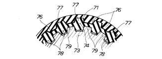
図8は図7の8部拡大図であり、一番外側の片歯付きベルト71の歯76・・・に両歯付きベルト74の上側の歯77・・・が嵌合し、この両歯付きベルト74の下側の歯78・・・に片歯付き1つのプーリ73の歯79・・・が嵌合することを説明した図である。
ところで、ベルトは片面に歯の付いた片歯付きベルトとし、駆動源で直接駆動する駆動プーリ及び、この駆動プーリと1つのプーリとを連結する駆動ベルトを備え、この駆動ベルトを両面に歯が付いた両歯付きベルトとし、この両歯付きベルトを1つのプーリに巻掛け、この様な両歯付きベルトに片歯付きベルトを巻掛けることで、1つのプーリに両歯付きベルトを巻掛け、この両歯付きベルトに片歯付きベルトを巻掛けたので、1つのプーリの上側(インナケース寄り)に本来必要であったプーリを削除でき、この1つのプーリで駆動軸からの動力を各駆動プーリに伝達することができる。この結果、多軸仮締め工具は軽量で低コスト型のものになるという利点がある。
FIG. 8 is an enlarged view of 8 parts in FIG. 7, and the
By the way, the belt is a single-toothed belt with teeth on one side, and includes a driving pulley that is directly driven by a driving source, and a driving belt that connects this driving pulley and one pulley. A double-toothed belt is attached, and this double-toothed belt is wrapped around one pulley, and a single-toothed belt is wrapped around such a double-toothed belt, so that a double-toothed belt is wrapped around one pulley. Since the single-toothed belt is wound around this double-toothed belt, the pulley that was originally necessary on the upper side of the one pulley (near the inner case) can be deleted, and the power from the drive shaft can be transferred to each pulley with this one pulley. Can be transmitted to the drive pulley. As a result, the multi-axis temporary tightening tool is advantageous in that it is lightweight and low-cost.
尚、本発明の多軸仮締め工具20は、実施の形態ではタイヤホイールのナットの組付けに適用したが、ナットドライブプーリ39・・・の数や大きさ、ナットドライブプーリ39・・・に巻掛けられたベルト41の外周長さ、その他細かい機構を変更して、タイヤホイール以外への適用も問題ない。
The multi-axis
アウタケース25とインナケース24の材質は樹脂としたが、プーリとベルト類の材質は特に限定しないが、機械的強度に優れたものを適用することが望ましい。
The material of the
本発明の多軸仮締め工具は、タイヤホイールのナット組付けに好適である。 The multi-axis temporary fastening tool of the present invention is suitable for assembling a nut of a tire wheel.
20…多軸仮締め工具、 21…本体、 21a…貫通穴、 23…駆動源、 24…インナケース、 25…アウタケース、 26…伝動手段、 34…駆動軸、 35…先端部、 36…駆動プーリ、 37…駆動ベルト、 38…従動プーリ、 39…ナットドライブプーリ、 39a…1つのプーリ、 41…ベルト、 42…支軸、 43…支持部、 44…支持部、 46,47…取付ボス。
DESCRIPTION OF
Claims (1)
前記多軸仮締め多軸工具は、
本体(21)と、本体(21)の握り部であるグリップ(22)と、本体(21)内蔵したモータ(23)と、モータ(23)の回転を減速させる減速機(31)と、減速機構(31)で駆動される駆動軸(34)とを備え、
前記本体(21)の前側には樹脂製のインナケース(24)を配置、固定し、該インナケース(24)の前側には樹脂製のアウタケース(25)を配置し、該アウタケース(25)はボルト(48)でインナケース(24)で締結し、
前記インナケース(24)とアウタケース(25)内には、ベルト・プーリ機構からなる伝動手段(26)を保持させ、
前記樹脂製のインナケース(24)、アウタケース(25)内に配設される前記伝動手段(26)は、複数個のナットに対応してナットを保持するソケット(45)を回転させる複数のナットドライブプーリ(39)と、複数のナットドライブプーリ(39)間に巻掛けられたベルト(41)と、前記駆動軸(34)の先端部に取り付けられた駆動プーリ(36)と、該駆動プーリ(36)により、駆動ベルト(37)を介して駆動され、前記ドライブプーリ(39)の一つ(39a)に同軸に設けた従動プーリ(38)と、からなり、前記本体(21)に保持されたモータ(23)により前記駆動プーリ(36)を回動させ、全てのナットドライブプーリ(39,39a)を一括して回動させるように構成し、
前記複数個のナットドライブプーリ(39)の支軸は、その両端部を前記アウタケース(25)、インナケース(24)の双方に支持部を介して支持させ、
前記駆動プーリ(36)は、前記駆動軸(34)と、アウタケース(25)に設けた支持部で支持するようにした、
ことを特徴とする多軸仮締め工具。 In the multi-axis temporary tightening tool used when temporarily tightening a plurality of nuts prior to final tightening,
The multi-axis temporary fastening multi-axis tool is:
A main body (21), a grip (22) as a grip portion of the main body (21), a motor (23) built in the main body (21), a speed reducer (31) for decelerating the rotation of the motor (23), and a deceleration A drive shaft (34) driven by a mechanism (31),
A resin inner case (24) is disposed and fixed on the front side of the main body (21), and a resin outer case (25) is disposed on the front side of the inner case (24). ) Is fastened with an inner case (24) with bolts (48),
In the inner case (24) and the outer case (25), transmission means (26) comprising a belt / pulley mechanism is held,
The transmission means (26) disposed in the resin inner case (24) and outer case (25) has a plurality of sockets (45) for holding nuts corresponding to the plurality of nuts. A nut drive pulley (39), a belt (41) wound around the plurality of nut drive pulleys (39), a drive pulley (36) attached to the tip of the drive shaft (34), and the drive A driven pulley (38) driven by a pulley (36) via a drive belt (37) and provided coaxially with one of the drive pulleys (39) (39a). The drive pulley (36) is rotated by the held motor (23), and all the nut drive pulleys (39, 39a) are rotated together,
The support shafts of the plurality of nut drive pulleys (39) have both ends supported by both the outer case (25) and the inner case (24) via support portions,
The drive pulley (36) is supported by the drive shaft (34) and a support portion provided on the outer case (25).
A multi-axis temporary fastening tool characterized by that.
Priority Applications (2)
| Application Number | Priority Date | Filing Date | Title |
|---|---|---|---|
| JP2003354205A JP4032019B2 (en) | 2003-10-14 | 2003-10-14 | Multi-axis temporary tightening tool |
| CN 200410083544 CN1607072B (en) | 2003-10-14 | 2004-10-09 | Multi-shaft temporary fastening tool |
Applications Claiming Priority (1)
| Application Number | Priority Date | Filing Date | Title |
|---|---|---|---|
| JP2003354205A JP4032019B2 (en) | 2003-10-14 | 2003-10-14 | Multi-axis temporary tightening tool |
Related Child Applications (1)
| Application Number | Title | Priority Date | Filing Date |
|---|---|---|---|
| JP2006290156A Division JP4048222B2 (en) | 2006-10-25 | 2006-10-25 | Multi-axis temporary tightening tool |
Publications (2)
| Publication Number | Publication Date |
|---|---|
| JP2005118912A JP2005118912A (en) | 2005-05-12 |
| JP4032019B2 true JP4032019B2 (en) | 2008-01-16 |
Family
ID=34612248
Family Applications (1)
| Application Number | Title | Priority Date | Filing Date |
|---|---|---|---|
| JP2003354205A Expired - Lifetime JP4032019B2 (en) | 2003-10-14 | 2003-10-14 | Multi-axis temporary tightening tool |
Country Status (2)
| Country | Link |
|---|---|
| JP (1) | JP4032019B2 (en) |
| CN (1) | CN1607072B (en) |
Families Citing this family (13)
| Publication number | Priority date | Publication date | Assignee | Title |
|---|---|---|---|---|
| CN105108687A (en) * | 2015-10-09 | 2015-12-02 | 京东方科技集团股份有限公司 | Multi-rod wrench |
| CN105269502A (en) * | 2015-10-27 | 2016-01-27 | 芜湖市泰能电热器具有限公司 | Nut rotating device for nut head mounting device |
| JP6414168B2 (en) * | 2016-09-26 | 2018-10-31 | トヨタ自動車株式会社 | Temporary fastening tool |
| CN108527228A (en) * | 2017-04-26 | 2018-09-14 | 宁波恒进自动化技术有限公司 | A kind of eclectic screw gun |
| CN108544413A (en) * | 2017-04-26 | 2018-09-18 | 宁波恒进自动化技术有限公司 | A kind of multiple gun head hand electric screw gun |
| CN108527233A (en) * | 2017-04-26 | 2018-09-14 | 宁波恒进自动化技术有限公司 | A kind of multiple gun header structure for eclectic screw gun |
| CN107791015B (en) * | 2017-11-29 | 2023-10-10 | 苏州优德通力科技有限公司 | Automatic locking clamp for rod penetrating nut |
| CN109648304A (en) * | 2018-12-20 | 2019-04-19 | 天长市龙亨电子有限公司 | A kind of charger production shell assembling equipment |
| WO2020232199A1 (en) * | 2019-05-15 | 2020-11-19 | Milwaukee Electric Tool Corporation | Offset base for router |
| DE102019207593A1 (en) * | 2019-05-23 | 2020-11-26 | Volkswagen Aktiengesellschaft | Assembly aid and procedure for assembly using the assembly aid |
| CN110666499A (en) * | 2019-10-25 | 2020-01-10 | 中国航发贵州红林航空动力控制科技有限公司 | Plane screw synchronizer |
| CN112388556B (en) * | 2020-11-03 | 2022-07-19 | 江西昌河阿古斯特直升机有限公司 | Quick constant force device of helicopter ring nut lock bolt |
| CN114800348B (en) * | 2022-02-28 | 2024-01-09 | 扬州新乐新材料有限公司 | Heavy electric wrench |
Family Cites Families (1)
| Publication number | Priority date | Publication date | Assignee | Title |
|---|---|---|---|---|
| DE3434850C2 (en) * | 1984-09-22 | 1986-04-03 | Daimler-Benz Ag, 7000 Stuttgart | Multiple screwdrivers |
-
2003
- 2003-10-14 JP JP2003354205A patent/JP4032019B2/en not_active Expired - Lifetime
-
2004
- 2004-10-09 CN CN 200410083544 patent/CN1607072B/en active Active
Also Published As
| Publication number | Publication date |
|---|---|
| JP2005118912A (en) | 2005-05-12 |
| CN1607072A (en) | 2005-04-20 |
| CN1607072B (en) | 2010-04-28 |
Similar Documents
| Publication | Publication Date | Title |
|---|---|---|
| JP4048222B2 (en) | Multi-axis temporary tightening tool | |
| JP2007030165A5 (en) | ||
| JP4032019B2 (en) | Multi-axis temporary tightening tool | |
| JP4516434B2 (en) | Multi-axis temporary tightening tool | |
| JP2000211892A (en) | Hoist | |
| JP7414491B2 (en) | Robot arm drive unit | |
| JP2004001682A (en) | Driving system for electric vehicle | |
| JP2007001445A5 (en) | ||
| JP2007507361A (en) | Power tool with planetary reduction gear unit | |
| CN100390001C (en) | Speed reduction gear of electric power steering device | |
| EP2441655A1 (en) | Assembled transmission device with bi-rotating directional input and constant rotating directional output | |
| JP4184857B2 (en) | Multi-axis wrench for temporary tightening | |
| JPWO2008142855A1 (en) | Rotational driving force transmission device | |
| JP5438556B2 (en) | Electric power steering device | |
| US7021167B2 (en) | Rotary joint mechanism | |
| KR950702484A (en) | BICYCLE HUB DYNAMO | |
| CN2310692Y (en) | Double-end motor-driven wheel removing tool | |
| JP2002250781A5 (en) | ||
| JP2003231064A (en) | Multiple shafts fastening tool | |
| KR20070064978A (en) | Power transmitting structure of a motor driven power steering system | |
| CN210859712U (en) | Speed change mechanism | |
| JPH0235684Y2 (en) | ||
| JP6040781B2 (en) | Electric power steering device | |
| JPS6338704Y2 (en) | ||
| KR200273965Y1 (en) | Driving apparatus for electric scooter |
Legal Events
| Date | Code | Title | Description |
|---|---|---|---|
| A977 | Report on retrieval |
Free format text: JAPANESE INTERMEDIATE CODE: A971007 Effective date: 20060830 |
|
| A131 | Notification of reasons for refusal |
Free format text: JAPANESE INTERMEDIATE CODE: A131 Effective date: 20060905 |
|
| A521 | Request for written amendment filed |
Free format text: JAPANESE INTERMEDIATE CODE: A523 Effective date: 20061025 |
|
| A131 | Notification of reasons for refusal |
Free format text: JAPANESE INTERMEDIATE CODE: A131 Effective date: 20070313 |
|
| A521 | Request for written amendment filed |
Free format text: JAPANESE INTERMEDIATE CODE: A523 Effective date: 20070427 |
|
| A711 | Notification of change in applicant |
Free format text: JAPANESE INTERMEDIATE CODE: A711 Effective date: 20070427 |
|
| A521 | Request for written amendment filed |
Free format text: JAPANESE INTERMEDIATE CODE: A523 Effective date: 20070511 |
|
| A521 | Request for written amendment filed |
Free format text: JAPANESE INTERMEDIATE CODE: A821 Effective date: 20070427 |
|
| A02 | Decision of refusal |
Free format text: JAPANESE INTERMEDIATE CODE: A02 Effective date: 20070717 |
|
| A521 | Request for written amendment filed |
Free format text: JAPANESE INTERMEDIATE CODE: A523 Effective date: 20070904 |
|
| A911 | Transfer to examiner for re-examination before appeal (zenchi) |
Free format text: JAPANESE INTERMEDIATE CODE: A911 Effective date: 20070921 |
|
| TRDD | Decision of grant or rejection written | ||
| A01 | Written decision to grant a patent or to grant a registration (utility model) |
Free format text: JAPANESE INTERMEDIATE CODE: A01 Effective date: 20071016 |
|
| A61 | First payment of annual fees (during grant procedure) |
Free format text: JAPANESE INTERMEDIATE CODE: A61 Effective date: 20071022 |
|
| R150 | Certificate of patent or registration of utility model |
Ref document number: 4032019 Country of ref document: JP Free format text: JAPANESE INTERMEDIATE CODE: R150 Free format text: JAPANESE INTERMEDIATE CODE: R150 |
|
| FPAY | Renewal fee payment (event date is renewal date of database) |
Free format text: PAYMENT UNTIL: 20101026 Year of fee payment: 3 |
|
| FPAY | Renewal fee payment (event date is renewal date of database) |
Free format text: PAYMENT UNTIL: 20101026 Year of fee payment: 3 |
|
| FPAY | Renewal fee payment (event date is renewal date of database) |
Free format text: PAYMENT UNTIL: 20111026 Year of fee payment: 4 |
|
| R250 | Receipt of annual fees |
Free format text: JAPANESE INTERMEDIATE CODE: R250 |
|
| FPAY | Renewal fee payment (event date is renewal date of database) |
Free format text: PAYMENT UNTIL: 20111026 Year of fee payment: 4 |
|
| FPAY | Renewal fee payment (event date is renewal date of database) |
Free format text: PAYMENT UNTIL: 20121026 Year of fee payment: 5 |
|
| R250 | Receipt of annual fees |
Free format text: JAPANESE INTERMEDIATE CODE: R250 |
|
| FPAY | Renewal fee payment (event date is renewal date of database) |
Free format text: PAYMENT UNTIL: 20131026 Year of fee payment: 6 |
|
| R250 | Receipt of annual fees |
Free format text: JAPANESE INTERMEDIATE CODE: R250 |
|
| R250 | Receipt of annual fees |
Free format text: JAPANESE INTERMEDIATE CODE: R250 |
|
| R250 | Receipt of annual fees |
Free format text: JAPANESE INTERMEDIATE CODE: R250 |
|
| R250 | Receipt of annual fees |
Free format text: JAPANESE INTERMEDIATE CODE: R250 |
|
| R250 | Receipt of annual fees |
Free format text: JAPANESE INTERMEDIATE CODE: R250 |
|
| R250 | Receipt of annual fees |
Free format text: JAPANESE INTERMEDIATE CODE: R250 |
|
| R250 | Receipt of annual fees |
Free format text: JAPANESE INTERMEDIATE CODE: R250 |
|
| R250 | Receipt of annual fees |
Free format text: JAPANESE INTERMEDIATE CODE: R250 |
|
| R250 | Receipt of annual fees |
Free format text: JAPANESE INTERMEDIATE CODE: R250 |
|
| R250 | Receipt of annual fees |
Free format text: JAPANESE INTERMEDIATE CODE: R250 |
|
| R250 | Receipt of annual fees |
Free format text: JAPANESE INTERMEDIATE CODE: R250 |
|
| EXPY | Cancellation because of completion of term |