JP4030665B2 - Hose guide device in concrete pump truck - Google Patents
Hose guide device in concrete pump truck Download PDFInfo
- Publication number
- JP4030665B2 JP4030665B2 JP32248798A JP32248798A JP4030665B2 JP 4030665 B2 JP4030665 B2 JP 4030665B2 JP 32248798 A JP32248798 A JP 32248798A JP 32248798 A JP32248798 A JP 32248798A JP 4030665 B2 JP4030665 B2 JP 4030665B2
- Authority
- JP
- Japan
- Prior art keywords
- hose
- boom
- concrete pump
- guide
- hose guide
- Prior art date
- Legal status (The legal status is an assumption and is not a legal conclusion. Google has not performed a legal analysis and makes no representation as to the accuracy of the status listed.)
- Expired - Lifetime
Links
Images


Landscapes
- Preparation Of Clay, And Manufacture Of Mixtures Containing Clay Or Cement (AREA)
Description
【0001】
【発明の属する技術分野】
本発明は車体上にコンクリートポンプとブームとを搭載したコンクリートポンプ車に関するものである。
【0002】
【従来の技術】
従来のコンクリートポンプ車は、特開昭55−161727号に開示されている如く、車体上に搭載された基部側ブームにコンクリートポンプに接続された配管を沿設し、基部側ブームの先部には伸縮可能な先端側ブームを設けてある。前記先部側ブームの先部には、配管先端に接続された打設ホースを支持するためのホースガイドを設けてあり、先端側ブームを伸縮させることにより打設ホースがホースガイド上を移動し、生コンクリートの打設場所を任意に変更できるようになっている。
【0003】
【発明が解決しようとする課題】
ところが前記構造にあっては、先端側ブームを伸縮させる際、ホースガイド上を打設ホースが移動することにより、打設ホースとホースガイドとの間に摩擦抵抗が生じるため、先端側ブームの伸縮作業に多大な労力が必要になるという欠点がある。そこで本発明は先部ブームの伸縮作業をわずかな労力にて簡単容易に行えるコンクリートポンプ車におけるホースガイド装置を提供するものである。
【0004】
【課題を解決するための手段】
本発明の請求項1は、車体上にコンクリートポンプと、基部ブームに伸縮可能な先部ブームを連結してなるブーム装置とを搭載し、前記各ブームにはコンクリートポンプに接続された移送配管を沿設してなり、さらに先部ブームの先端には移送配管の先端に接続された打設ホースを支持するホースガイドを設けてなるコンクリートポンプ車において、前記ホースガイドは、全体が略円弧状を形成し、さらに断面も打設ホース外形に合わせて略半円弧状にするとともに半円弧状の底部の所定間隔を置いた複数箇所に打設ホースを支持するガイドローラを設けたことを特徴とするものである。
【0005】
これにより打設ホースとホースガイドとの摩擦抵抗が小さくなることから先部ブームの伸縮作業を簡単容易に行うことができる。請求項2は、請求項1記載のホースガイド装置において、前記ガイドローラは、打設ホース外形に合わせた鼓状にしたことを特徴とするものである。これにより打設ホースを常時ホースガイドの中心に導くことができ、打設ホースが蛇行するのを防止できる。請求項3の発明は、請求項1又は請求項2に記載のコンクリートポンプ車におけるホースガイド装置において、前記半円弧状の底部は、ホースガイドの全長に渡って固定した。
【0006】
【発明の実施の形態】
以下、本発明の実施の形態を図面にて説明すると、図1及び図2において、1はコンクリートポンプ車の車体であって、該車体1上には車体1前部にブーム装置2を、車体1後部にコンクリートポンプ3とホッパ4とを搭載している。前記ブーム装置2は屈折可能な基部ブーム5と伸縮可能な先部ブーム6とからなり、走行時には図1の如く車体1上に折り畳まれた格納位置にあり、打設作業時には図2の如く伸長させて打設作業を行うようになっている。
【0007】
前記基部ブーム5は、車体1上に旋回可能に設けられた旋回台7に取付支柱8を立設し、前記取付支柱8の上端に第1ブーム9の基端を軸支してあり、取付支柱8に設けた第1シリンダ10により第1ブーム9が起伏するようになっている。前記第1ブーム9の先端には第2ブーム11の基端を軸支してあり、前記第1ブーム9に設けた第2シリンダ12により第2ブーム11が起伏するようになっている。
【0008】
前記先部ブーム6は、第2ブーム11の先端に軸支され、第2ブーム11に設けられた第3シリンダ13により起伏するようになっている。また前記先部ブーム6は図4及び図5に示す如く外筒14に内筒15を伸縮自在に設けてなり、前記外筒14内と内筒15内には、内筒15を伸縮させるための伸縮シリンダ16が配設されている。前記伸縮シリンダ16の基部は内筒15に軸支され、ロッド17はその先部をボス部18に嵌挿されたピン19に軸支されている。
【0009】
前記ロッド17先部の近接位置であって、ブーム装置2格納位置における外筒14の下面には開口部20を形成してあり、前記開口部20には接続部材21を外筒14の下方に突出した状態で配設し、前記接続部材21はその下面からボルト22にて伸縮シリンダ16のロッド17先部に固定されている。前記接続部材21はチェック弁(図示せず)を内装し、前記開口部20より下方位置の側面には油圧ホース等(図示せず)を接続するための接続口23を設けてある。これにより伸縮シリンダ16のメンテナンス作業をする際には、先部ブーム6の外部から容易に行うことができるようになっている。
【0010】
前記各ブーム5、6にはコンクリートポンプ3の吐出管24に接続された移送配管25を沿設し、前記移送配管25の先部には図3に示す如く可撓性の打設ホース26を接続してある。前記打設ホース26は、先部ブーム6の内筒15先端に設けられたホースガイド27により案内支持されるようになっており、打設場所によって先部ブーム6を伸縮させて打設ホース26の長さを適宜変更することにより打設ホース26先端部を操作しやすいようになっている。28は車体1後部に設けられた固縛部材で、図1のブーム装置2格納時に打設ホース26の先端部を固定するようになっている。
【0011】
以下前記ホースガイド27について説明すると、前記ホースガイド27は図6乃至図9に示す如く、略円弧状に形成された左右一対の上部支持部材29間に略半円弧状のガイド部材30を所定間隔を設けて複数個設けてある。前記上部支持部材29の基部には側方に突出した連結部材31を固定してあり、前記連結部材31は前記内筒15の先部側面に固定された固定部材32にボルト33止めされている。
【0012】
前記ガイド部材30の底部には略円弧状に形成された左右一対の下部支持部材34を固定してあり、前記下部支持部材34には溝部35を所定間隔を設けて複数個穿設してある。前記各溝部35には打設ホース26の下面を支持しうるガイドローラ36の軸部37をナット38にて軸支してあり、打設ホース26が移動するとガイドローラ36が回転し、摩擦抵抗が非常に小さくなるようになっている。前記ガイドローラ36の外周面には打設ホース26の外形に合わせた鼓状のガイド面39を形成してあり、打設ホース26が左右へ蛇行するのを防止するようになっている。
【0013】
40は前記上部支持部材29間に軸支された補助ローラで、前記補助ローラ40にて打設ホース26がホースガイド27から外れるのを防止するようになっている。41はホースガイド27を補強するための補強部材で、該補強部材41は一端を連結部材31に固定し他端を上部支持部材29先部のガイド部材30に固定してある。
【0014】
本発明は前記の如き構成で、次に作用について説明する。生コンクリートの打設作業を行うには、まず図1の格納位置から第1ブーム9、第2ブーム11及び先部ブーム6を起立させ先部ブーム6の先端を打設場所に近接させ、打設ホース26を打設場所に臨ませる。その状態で生コンクリートをホッパ4内に入れ、コンクリートポンプ3を作動させると、生コンクリートは吐出管24から移送配管25に圧送され、打設ホース26により打設場所にてホッパ4内に供給された生コンクリートを移送配管25、打設ホース26を通って打設させる。
【0015】
続いて近くの打設場所にて打設作業を行う場合には、基部ブーム5を起伏作動させることなく、先部ブーム6の伸縮シリンダ16により先部ブーム6を伸長させ、図2の如く打設ホース26の長さを適宜変更しながら打設ホース26の先端部を打設場所に移動させる。その際、打設ホース26はホースガイド27のガイドローラ36上を移動するため、摩擦抵抗が小さくスムーズに案内させることができる。
【0016】
その後、前記と同様に生コンクリートを打設する。打設作業終了後は、伸縮シリンダ16により先部ブーム6を収縮させた後、各油圧シリンダ10、12、13を収縮または伸長作動させることにより各ブーム6、9、11を屈折させて車体1上に格納させる。ところで打設作業終了後は定期的にメンテナンス作業を行うが、伸縮シリンダ16の場合は、接続口23に接続された油圧ホース等を取り外した後、ボルト22を外して接続部材21を伸縮シリンダ16から下方に取り出し、チェック弁等のメンテナンスを行う。その際、前記接続口23及びボルト22は先部ブーム6より外部にあるため、メンテナンス作業を容易に行うことができる。また前記開口部20はブーム装置2格納位置における外筒14の下面に形成されているため、他のブームに干渉することなくメンテナンス作業を簡単容易に行うことができる。
【0017】
【発明の効果】
以上のように請求項1の発明によれば、ホースガイドに複数のガイドローラを、所定間隔を置いて設けるようにしたので、打設ホースとガイドローラとの摩擦抵抗が小さくなり、先部ブームの伸長作業をわずかな労力にて簡単容易に行うことができる。また請求項2の発明によれば、ガイドローラを鼓状に形成したため、打設ホースが左右に蛇行するのを防止でき、打設ホースの伸長作業をより円滑に行うことができる。
【図面の簡単な説明】
【図1】 本発明の全体図である。
【図2】 図1のブーム装置伸長時の側面図である。
【図3】 図1のブーム装置先部の拡大平面図である。
【図4】 先部ブームの側部断面図である。
【図5】 図4の要部縦断面図である。
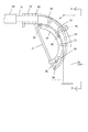
【図6】 ホースガイドの側面図である。
【図7】 図6のホースガイドの正面図である。
【図8】 図6のガイドローラの拡大図である。
【図9】 図8の矢視断面図である。
【符号の説明】
1 車体
2 ブーム装置
3 コンクリートポンプ
5 基部ブーム
6 先部ブーム
25 移送配管
26 打設ホース
27 ホースガイド
36 ガイドローラ[0001]
BACKGROUND OF THE INVENTION
The present invention relates to a concrete pump vehicle in which a concrete pump and a boom are mounted on a vehicle body.
[0002]
[Prior art]
As disclosed in Japanese Patent Application Laid-Open No. 55-161727, a conventional concrete pump truck has a pipe connected to a concrete pump mounted on a base-side boom mounted on a vehicle body, and is connected to a tip of the base-side boom. Is provided with a telescopic boom. A hose guide for supporting a placement hose connected to the tip of the pipe is provided at the tip of the tip side boom, and the placement hose moves on the hose guide by expanding and contracting the tip side boom. , The place where ready-mixed concrete is placed can be changed arbitrarily.
[0003]
[Problems to be solved by the invention]
However, in the above structure, when the distal boom is extended and contracted, the leading hose moves on the hose guide, so that a frictional resistance is generated between the casting hose and the hose guide. There is a drawback that a lot of labor is required for the work. Therefore, the present invention provides a hose guide device in a concrete pump truck that can easily and easily perform a telescopic operation of the front boom with a little effort.
[0004]
[Means for Solving the Problems]
According to a first aspect of the present invention, a concrete pump and a boom device formed by connecting a telescopic boom to the base boom are mounted on the vehicle body, and each boom is provided with a transfer pipe connected to the concrete pump. Further, in the concrete pump vehicle in which a hose guide for supporting a driving hose connected to the tip of the transfer pipe is provided at the tip of the front boom, the hose guide has a substantially arc shape as a whole. Further, the guide roller is provided with a guide roller for supporting the casting hose at a plurality of positions at a predetermined interval on the bottom of the semicircular arc shape, and the cross section is formed into a substantially semicircular arc shape according to the outer shape of the casting hose. Is.
[0005]
As a result, the frictional resistance between the placing hose and the hose guide is reduced, so that the telescopic work of the front boom can be performed easily and easily. According to a second aspect of the present invention, in the hose guide device according to the first aspect, the guide roller is formed in a drum shape that matches the outer shape of the hose. Thereby, the driving hose can be always guided to the center of the hose guide, and the driving hose can be prevented from meandering. According to a third aspect of the present invention, in the hose guide device in the concrete pump vehicle according to the first or second aspect, the semicircular arc-shaped bottom portion is fixed over the entire length of the hose guide.
[0006]
DETAILED DESCRIPTION OF THE INVENTION
DESCRIPTION OF THE PREFERRED EMBODIMENTS Embodiments of the present invention will be described below with reference to the drawings. In FIGS. 1 and 2,
[0007]
The base boom 5 is provided with a mounting column 8 erected on a swivel 7 that is turnable on the
[0008]
The
[0009]
An
[0010]
Each
[0011]
Hereinafter, the
[0012]
A pair of left and right
[0013]
[0014]
The present invention is constructed as described above, and the operation will be described next. In order to perform the placing operation of ready-mixed concrete, first, the
[0015]
Subsequently, when performing a driving operation at a nearby driving site, the
[0016]
Thereafter, ready-mixed concrete is placed in the same manner as described above. After the driving operation is finished, the
[0017]
【The invention's effect】
As described above, according to the first aspect of the present invention, since the plurality of guide rollers are provided in the hose guide at predetermined intervals, the friction resistance between the placing hose and the guide roller is reduced, and the front boom is reduced. Can be easily and easily performed with little effort. According to the invention of
[Brief description of the drawings]
FIG. 1 is an overall view of the present invention.
FIG. 2 is a side view when the boom device of FIG. 1 is extended.
FIG. 3 is an enlarged plan view of the boom device front portion of FIG. 1;
FIG. 4 is a side sectional view of a front boom.
5 is a longitudinal sectional view of a main part of FIG. 4. FIG.
FIG. 6 is a side view of a hose guide.
7 is a front view of the hose guide of FIG. 6. FIG.
FIG. 8 is an enlarged view of the guide roller of FIG.
9 is a cross-sectional view taken along the arrow in FIG.
[Explanation of symbols]
DESCRIPTION OF
Claims (3)
Priority Applications (1)
| Application Number | Priority Date | Filing Date | Title |
|---|---|---|---|
| JP32248798A JP4030665B2 (en) | 1998-11-12 | 1998-11-12 | Hose guide device in concrete pump truck |
Applications Claiming Priority (1)
| Application Number | Priority Date | Filing Date | Title |
|---|---|---|---|
| JP32248798A JP4030665B2 (en) | 1998-11-12 | 1998-11-12 | Hose guide device in concrete pump truck |
Publications (2)
| Publication Number | Publication Date |
|---|---|
| JP2000141353A JP2000141353A (en) | 2000-05-23 |
| JP4030665B2 true JP4030665B2 (en) | 2008-01-09 |
Family
ID=18144197
Family Applications (1)
| Application Number | Title | Priority Date | Filing Date |
|---|---|---|---|
| JP32248798A Expired - Lifetime JP4030665B2 (en) | 1998-11-12 | 1998-11-12 | Hose guide device in concrete pump truck |
Country Status (1)
| Country | Link |
|---|---|
| JP (1) | JP4030665B2 (en) |
Families Citing this family (1)
| Publication number | Priority date | Publication date | Assignee | Title |
|---|---|---|---|---|
| CN109421240B (en) * | 2017-09-01 | 2021-04-13 | 威海三巨模具有限公司 | Vertical injection molding machine mould temperature control line protector |
-
1998
- 1998-11-12 JP JP32248798A patent/JP4030665B2/en not_active Expired - Lifetime
Also Published As
| Publication number | Publication date |
|---|---|
| JP2000141353A (en) | 2000-05-23 |
Similar Documents
| Publication | Publication Date | Title |
|---|---|---|
| WO2007020790A1 (en) | Support device | |
| JP4030665B2 (en) | Hose guide device in concrete pump truck | |
| JP3678592B2 (en) | Telescopic cylinder mounting structure in boom device | |
| JP3939415B2 (en) | Reinforcing plate installation device and installation method | |
| JP3689268B2 (en) | Concrete pump truck | |
| JP3760163B2 (en) | Steel pipe pile burial method and crane vehicle platform used for it | |
| JP2002046092A (en) | Piping device for slide arm | |
| JP2617312B2 (en) | Fluid transfer vehicles | |
| JP3195906B2 (en) | Hopper support structure of concrete pump truck | |
| JPH10306675A (en) | Leader attachment for civil engineering and construction machine | |
| JP2000054424A (en) | Dredging device for manhole of great depth | |
| JPS5953985B2 (en) | Hose guide device in fluid transfer equipment | |
| JP3706330B2 (en) | Multi-stage telescopic arm and working machine | |
| JPH0768764B2 (en) | Storage structure for placing hoses in concrete pump trucks | |
| JPH06294297A (en) | Device for supporting reaction of gable mold for use in lining tunnel with concrete | |
| JPH10184286A (en) | Side-pressure supporter of form for concrete lining | |
| JPH1030339A (en) | Joining piping-device for crawler-type concrete distributor | |
| JP4264311B2 (en) | Telescopic boom | |
| JPH0734108Y2 (en) | Boom device for concrete pump car | |
| JP3322473B2 (en) | Aerial work vehicle with telescopic boom | |
| JP3795964B2 (en) | Vertical winding formwork device | |
| JPH0332188Y2 (en) | ||
| JP3137929B2 (en) | Hydraulic piping of telescopic arm in construction machinery | |
| JPH0442516B2 (en) | ||
| JPH10299374A (en) | Leader attachment of civil engineering and construction machinery |
Legal Events
| Date | Code | Title | Description |
|---|---|---|---|
| A977 | Report on retrieval |
Free format text: JAPANESE INTERMEDIATE CODE: A971007 Effective date: 20040525 |
|
| A131 | Notification of reasons for refusal |
Free format text: JAPANESE INTERMEDIATE CODE: A131 Effective date: 20060808 |
|
| A521 | Written amendment |
Free format text: JAPANESE INTERMEDIATE CODE: A523 Effective date: 20061010 |
|
| RD02 | Notification of acceptance of power of attorney |
Free format text: JAPANESE INTERMEDIATE CODE: A7422 Effective date: 20061010 |
|
| A02 | Decision of refusal |
Free format text: JAPANESE INTERMEDIATE CODE: A02 Effective date: 20070606 |
|
| A521 | Written amendment |
Free format text: JAPANESE INTERMEDIATE CODE: A523 Effective date: 20070806 |
|
| A911 | Transfer to examiner for re-examination before appeal (zenchi) |
Free format text: JAPANESE INTERMEDIATE CODE: A911 Effective date: 20070830 |
|
| TRDD | Decision of grant or rejection written | ||
| A01 | Written decision to grant a patent or to grant a registration (utility model) |
Free format text: JAPANESE INTERMEDIATE CODE: A01 Effective date: 20070927 |
|
| A61 | First payment of annual fees (during grant procedure) |
Free format text: JAPANESE INTERMEDIATE CODE: A61 Effective date: 20071017 |
|
| R150 | Certificate of patent or registration of utility model |
Free format text: JAPANESE INTERMEDIATE CODE: R150 |
|
| FPAY | Renewal fee payment (event date is renewal date of database) |
Free format text: PAYMENT UNTIL: 20101026 Year of fee payment: 3 |
|
| FPAY | Renewal fee payment (event date is renewal date of database) |
Free format text: PAYMENT UNTIL: 20101026 Year of fee payment: 3 |
|
| FPAY | Renewal fee payment (event date is renewal date of database) |
Free format text: PAYMENT UNTIL: 20111026 Year of fee payment: 4 |
|
| FPAY | Renewal fee payment (event date is renewal date of database) |
Free format text: PAYMENT UNTIL: 20111026 Year of fee payment: 4 |
|
| FPAY | Renewal fee payment (event date is renewal date of database) |
Free format text: PAYMENT UNTIL: 20121026 Year of fee payment: 5 |
|
| FPAY | Renewal fee payment (event date is renewal date of database) |
Free format text: PAYMENT UNTIL: 20131026 Year of fee payment: 6 |
|
| EXPY | Cancellation because of completion of term |