JP4030429B2 - Process for the production of patterned monolayer or multilayer composites of zeolite or similar molecular sieves and composites produced thereby - Google Patents
Process for the production of patterned monolayer or multilayer composites of zeolite or similar molecular sieves and composites produced thereby Download PDFInfo
- Publication number
- JP4030429B2 JP4030429B2 JP2002539130A JP2002539130A JP4030429B2 JP 4030429 B2 JP4030429 B2 JP 4030429B2 JP 2002539130 A JP2002539130 A JP 2002539130A JP 2002539130 A JP2002539130 A JP 2002539130A JP 4030429 B2 JP4030429 B2 JP 4030429B2
- Authority
- JP
- Japan
- Prior art keywords
- zeolite
- group
- molecular sieve
- patterned
- porous molecular
- Prior art date
- Legal status (The legal status is an assumption and is not a legal conclusion. Google has not performed a legal analysis and makes no representation as to the accuracy of the status listed.)
- Expired - Fee Related
Links
Images


Classifications
-
- B—PERFORMING OPERATIONS; TRANSPORTING
- B32—LAYERED PRODUCTS
- B32B—LAYERED PRODUCTS, i.e. PRODUCTS BUILT-UP OF STRATA OF FLAT OR NON-FLAT, e.g. CELLULAR OR HONEYCOMB, FORM
- B32B18/00—Layered products essentially comprising ceramics, e.g. refractory products
-
- B—PERFORMING OPERATIONS; TRANSPORTING
- B82—NANOTECHNOLOGY
- B82Y—SPECIFIC USES OR APPLICATIONS OF NANOSTRUCTURES; MEASUREMENT OR ANALYSIS OF NANOSTRUCTURES; MANUFACTURE OR TREATMENT OF NANOSTRUCTURES
- B82Y30/00—Nanotechnology for materials or surface science, e.g. nanocomposites
-
- C—CHEMISTRY; METALLURGY
- C04—CEMENTS; CONCRETE; ARTIFICIAL STONE; CERAMICS; REFRACTORIES
- C04B—LIME, MAGNESIA; SLAG; CEMENTS; COMPOSITIONS THEREOF, e.g. MORTARS, CONCRETE OR LIKE BUILDING MATERIALS; ARTIFICIAL STONE; CERAMICS; REFRACTORIES; TREATMENT OF NATURAL STONE
- C04B35/00—Shaped ceramic products characterised by their composition; Ceramics compositions; Processing powders of inorganic compounds preparatory to the manufacturing of ceramic products
- C04B35/01—Shaped ceramic products characterised by their composition; Ceramics compositions; Processing powders of inorganic compounds preparatory to the manufacturing of ceramic products based on oxide ceramics
- C04B35/16—Shaped ceramic products characterised by their composition; Ceramics compositions; Processing powders of inorganic compounds preparatory to the manufacturing of ceramic products based on oxide ceramics based on silicates other than clay
- C04B35/18—Shaped ceramic products characterised by their composition; Ceramics compositions; Processing powders of inorganic compounds preparatory to the manufacturing of ceramic products based on oxide ceramics based on silicates other than clay rich in aluminium oxide
-
- C—CHEMISTRY; METALLURGY
- C04—CEMENTS; CONCRETE; ARTIFICIAL STONE; CERAMICS; REFRACTORIES
- C04B—LIME, MAGNESIA; SLAG; CEMENTS; COMPOSITIONS THEREOF, e.g. MORTARS, CONCRETE OR LIKE BUILDING MATERIALS; ARTIFICIAL STONE; CERAMICS; REFRACTORIES; TREATMENT OF NATURAL STONE
- C04B2237/00—Aspects relating to ceramic laminates or to joining of ceramic articles with other articles by heating
- C04B2237/02—Aspects relating to interlayers, e.g. used to join ceramic articles with other articles by heating
- C04B2237/12—Metallic interlayers
- C04B2237/123—Metallic interlayers based on iron group metals, e.g. steel
-
- C—CHEMISTRY; METALLURGY
- C04—CEMENTS; CONCRETE; ARTIFICIAL STONE; CERAMICS; REFRACTORIES
- C04B—LIME, MAGNESIA; SLAG; CEMENTS; COMPOSITIONS THEREOF, e.g. MORTARS, CONCRETE OR LIKE BUILDING MATERIALS; ARTIFICIAL STONE; CERAMICS; REFRACTORIES; TREATMENT OF NATURAL STONE
- C04B2237/00—Aspects relating to ceramic laminates or to joining of ceramic articles with other articles by heating
- C04B2237/30—Composition of layers of ceramic laminates or of ceramic or metallic articles to be joined by heating, e.g. Si substrates
- C04B2237/32—Ceramic
- C04B2237/34—Oxidic
- C04B2237/341—Silica or silicates
-
- C—CHEMISTRY; METALLURGY
- C04—CEMENTS; CONCRETE; ARTIFICIAL STONE; CERAMICS; REFRACTORIES
- C04B—LIME, MAGNESIA; SLAG; CEMENTS; COMPOSITIONS THEREOF, e.g. MORTARS, CONCRETE OR LIKE BUILDING MATERIALS; ARTIFICIAL STONE; CERAMICS; REFRACTORIES; TREATMENT OF NATURAL STONE
- C04B2237/00—Aspects relating to ceramic laminates or to joining of ceramic articles with other articles by heating
- C04B2237/30—Composition of layers of ceramic laminates or of ceramic or metallic articles to be joined by heating, e.g. Si substrates
- C04B2237/32—Ceramic
- C04B2237/34—Oxidic
- C04B2237/345—Refractory metal oxides
- C04B2237/346—Titania or titanates
-
- C—CHEMISTRY; METALLURGY
- C04—CEMENTS; CONCRETE; ARTIFICIAL STONE; CERAMICS; REFRACTORIES
- C04B—LIME, MAGNESIA; SLAG; CEMENTS; COMPOSITIONS THEREOF, e.g. MORTARS, CONCRETE OR LIKE BUILDING MATERIALS; ARTIFICIAL STONE; CERAMICS; REFRACTORIES; TREATMENT OF NATURAL STONE
- C04B2237/00—Aspects relating to ceramic laminates or to joining of ceramic articles with other articles by heating
- C04B2237/50—Processing aspects relating to ceramic laminates or to the joining of ceramic articles with other articles by heating
- C04B2237/76—Forming laminates or joined articles comprising at least one member in the form other than a sheet or disc, e.g. two tubes or a tube and a sheet or disc
- C04B2237/765—Forming laminates or joined articles comprising at least one member in the form other than a sheet or disc, e.g. two tubes or a tube and a sheet or disc at least one member being a tube
Landscapes
- Engineering & Computer Science (AREA)
- Chemical & Material Sciences (AREA)
- Ceramic Engineering (AREA)
- Nanotechnology (AREA)
- Materials Engineering (AREA)
- Structural Engineering (AREA)
- Organic Chemistry (AREA)
- Physics & Mathematics (AREA)
- Composite Materials (AREA)
- Condensed Matter Physics & Semiconductors (AREA)
- General Physics & Mathematics (AREA)
- Crystallography & Structural Chemistry (AREA)
- Manufacturing & Machinery (AREA)
- Silicates, Zeolites, And Molecular Sieves (AREA)
- Laminated Bodies (AREA)
- Solid-Sorbent Or Filter-Aiding Compositions (AREA)
Abstract
Description
【0001】
【発明の属する技術分野】
本発明はゼオライトまたは類似分子ふるい(zeotype molecular sieve)のパターン化された単層または多層複合体及びこれの製造方法に関するものである。具体的には、本発明は表面にハイドロキシ基を有する物質、チオル基(-SH)またはアミノ基(-NH2)と反応できる金属、そして反応性作用基を有する高分子重合体から選択された基質を使用して、基質表面に連結化合物を結合した後、紫外線を選択的に照射するか、基質表面の一部に連結化合物またはオクタデシルトリクロロシランのような遮蔽化合物を選択的に塗布するか、または基質表面の一部に白金のような金属を蒸着法で選択的に塗布した後連結化合物を結合させることにより、連結化合物のパターンを基質表面に鋳型して、及び前記パターンに従ってゼオライトまたは類似分子ふるいを選択的に結合させることで構成された、ゼオライトまたは類似分子ふるいのパターン化された単層または多層複合体の製造方法及びこのように製造された複合体に関するものである。
【0002】
【従来の技術】
ゼオライトを始めとした多様な分子ふるいは実生活と産業界で非常に広範囲に使用される重要な物質である。このようなゼオライト粒子は普通微細な粉末で存在するため使用上利点もあるが、短所もたくさん有している。このようなゼオライト粒子を多様な基質に化学結合により堅く結合させると産業的に多様な有用性を有する。また、分子ふるい粒子が基質に対して一定な配向性(orientation)を有するように調節するということも新しい物性が期待できるということから大きい意味を有する。さらに、基質表面に対して選択的にゼオライトを結合することができる方法があれば既存物質から見つけられない新しい特性を期待することができる。また、分子ふるい粒子が基質に対して一定な配向性を有するように調節することができれば新素材分野で画期的な発展を達成することができる。
【0003】
ゼオライトは結晶性アルミノシリケート(crystalline aluminosilicate)を総称して、骨格をなすアルミノシリケートはアルミニウムがある所ごとに陰電荷を帯びているので電荷相殺のための陽イオンが細孔(pore)の中に存在して細孔内の余りの空間は普通水分子で湛えられている。ゼオライトが有する3次元的な細孔構造は形と大きさによって多様であるが細孔の直径が大抵分子の大きさに該当する。従って、ゼオライトは細孔の大きさと形によって細孔の中に受け入れる分子に対した形状選択性(shape selectivity)を有するため分子ふるい(molecular sieve)とも称する。
【0004】
このようなゼオライトは化学的組成と構造、前処理方法などによって多様な化学的、物理的性質を示している。特に、水素イオンが陽イオンに置換されたゼオライトは高温でもよく耐えるゼオライトの特性と結び付けられて石油化学産業で原油のクレッキング触媒として広く使用されている。その他にもゼオライトは脱水乾燥剤、吸着剤、気体浄化剤、イオン交換剤、洗剤添加剤、土壌改良剤など広範囲に使用されていて、センサー担体としての応用に関する研究も活発に進行されている。
【0005】
一方、ゼオライトの骨格構造をなす元素であるシリコン(Si)とアルミニウム(Al)の代わりに他の元素でこれらを一部または全体的に置換させたゼオライト類似分子ふるい(zeotype molecular sieves)が知られている。例えば、アルミニウムを完全に除去させた多孔性シリカ(MCM-series mesoporous silica 及びsilicaliteなど)とシリコンを燐(P)に代替させたアルポ(AlPO4)系分子ふるい、そしてこのようなゼオライト及び類似分子ふるいの骨格にTi、Mn、Co、Fe、Znなどの多様な金属元素を一部置換させて得られる類似分子ふるいが知られていて広く応用されている。
【0006】
このようなゼオライト及び類似分子ふるいの特性をさらに効果的に利用するためにガラス、セラミック、重合体、金属などのような基質の表面にゼオライトを付着させようとする研究が活発に進行されてきた[参照:L.C.Boudreau, J.A. Kuck, M.Tsapatsis, J.Membr.Sci.1999, 152, 41-59; Z. Li, C.Lai, T.E.Mallouk, Inorg.Chem.1989, 28, 178-182; L.C.Boudreau, J.A.Kuck, M.Tsapatsis, J.Membr.Sci.1999, 152, 41-59; J.C.Jansen, D.Kashchiev, A.Erdem-Senatalar, Stud.Surf.Sci.Catal.1994, 85, 215-250; R. Althoff, K. Unger, F. Schuff, Microporous Mater. 1994, 2, 557-562]。
【0007】
しかし、既存の方法では、ゼオライト単層膜の厚さ及び配向性を完全に調節することは難しくて、本発明者らは基質とゼオライトに各々反応性の作用基を有する連結化合物を使用して基質及びゼオライトの表面を化学的に変形することにより、基質-連結化合物-ゼオライト複合体を簡便かつ経済的に製造する方法を開発して特許出願した(参考:韓国特許出願第2000-19667号)。
【0008】
一方、ガラス、セラミック、重合体、金属などのような基質の表面にパターンを鋳型する方法も既に多い研究が進行されている。既存に知られているパターン鋳型方法は大いに三つに分けられる。一番目は、紫外線を照射する際、光マスク(photomask)を用いて選択的にパターンを鋳型する方式である。二番目は、ポリジメチルシロキサン(polydimethylsiloxane、PCMS)を用いて予め鋳型をとってこれにオクタデシルトリクロロシランのような遮蔽化合物または連結化合物をつけて基質にスタンプを押すようにパターンを鋳型する方法である。三番目はパターン化されたメタルグリド(metal grid)を基質に密着させてこれに白金のような金属の蒸着膜を選択的に付着してパターンを鋳型する方法である。
【0009】
以上のように、基質表面にパターンを鋳型することにより基質表面に刻まれたパターンによって相互異なる化学的な反応性を有するように表面を変形することはよく知られている技術である。しかし、ゼオライトのような粒子の表面を化学的な反応性を有するように変形して、粒子を基質表面に化学結合させることは技術的に難しい問題を有している。
【0010】
【発明が解決しようとする課題】
これに本発明者らは既存に知られていた溶液状態での化学反応が物体の表面で選択的に起こるように工程(procedure)上の大きい発展を成した。また、このように開発した方法を通じて多様な複合体を製造するために広範囲な研究を進行した。
【0011】
その結果、基質に対して紫外線(UV)、遮蔽化合物及び金属蒸着(例:白金)などを用いてパターンを鋳型して、このように得られたパターン化された基質表面に化学反応を通じてゼオライトを接合することによってパターン化されたゼオライト単層膜及び多層膜を製造しようとし、このような複合体の耐久性及び配向性を高めようとした。
【0012】
前述したように、紫外線(UV)、連結化合物または遮蔽化合物(例:オクタデシルトリクロロシラン)及び金属(例:白金)蒸着などを用いて基質表面にパターンを鋳型することにより基質の表面がパターンに従って異なる化学的な反応性を有するように変形することはよく知られている過程であるが、このように表面-変性された基質の表面にパターン化されたゼオライト層を形成するのは現在まで知られたことがない。
【0013】
しかし、前述したように本発明者らが出願した特許出願第2000-19667号に記載された方法、即ちゼオライトを、連結化合物を仲介とする化学結合を通じて基質上に結合させる方法を用いる場合、パターンが鋳型された基質上にゼオライト層を前記パターンに従って容易に積層させることができ、単層だけではなく多層積層が可能であり、各層ごとにパターンの形態及び材質(分子ふるいの類型)を多様に調節することができるということを発見した。
【0014】
【発明の構成】
本発明は、基質-連結化合物-ゼオライトまたは類似分子ふるいからなる複合体の製造方法において、表面にハイドロキシ基を有する物質、チオル基(-SH)またはアミノ基(-NH2)と反応できる金属、そして反応性作用基を有する高分子重合体から選択された基質を使用して、基質表面に連結化合物を結合した後紫外線を選択的に照射するか、基質表面の一部に連結化合物またはオクタデシルトリクロロシランのような遮蔽化合物を選択的に塗布するか、または基質表面の一部に白金のような金属を蒸着法で選択的に塗布した後連結化合物を結合させることにより、連結化合物のパターンを基質表面に鋳型して、及び前記パターンに従ってゼオライトまたは類似分子ふるいを選択的に結合させることで構成された、ゼオライトまたは類似分子ふるいのパターン化された単層及び多層複合体及びこれの製造方法に関するものである。
【0015】
従って、本発明の一番目の目的は、基質-連結化合物-ゼオライトまたは類似分子ふるいからなる複合体の製造方法において、(i) 基質表面に連結化合物を結合させて、(ii)パターンを有する光マスクを使用し基質をUV-照射させて基質に結合された連結化合物またはこれの作用基を変性させて、(iii)UV-照射された部分またはUV-照射されてない部分にゼオライト層または類似分子ふるい層を選択的に形成させて、(iv)必要に応じて焼成することで構成されることを特徴とするゼオライトまたは類似分子ふるいのパターン化された単層または多層複合体の製造方法を提供することである。
【0016】
また、前記一番目の目的の製造方法において、UV-照射された部分またはUV-照射されていない部分を除去した後、ゼオライトまたは類似分子ふるいからなる層を形成させることもできる。
【0017】
本発明の二番目の目的は、基質-連結化合物-ゼオライトまたは類似分子ふるいからなる複合体の製造方法において、(i) 基質表面の一部に、連結化合物または遮蔽化合物を所定のパターンを有するように結合させて、(ii)余りの基質表面には遮蔽化合物または連結化合物を結合させて、(iii)連結化合物が結合された部分にゼオライト層または類似分子ふるい層を選択的に形成させて、(iv)必要に応じて焼成することで構成されることを特徴とするゼオライトまたは類似分子ふるいのパターン化された単層または多層複合体の製造方法を提供することである。
【0018】
前記二番目の目的の製造方法において、基質表面の一部に連結化合物または遮蔽化合物をスタンプ法で塗布することができる。
【0019】
本発明の三番目の目的は、基質-連結化合物-ゼオライトまたは類似分子ふるいからなる複合体の製造方法において、(i) 基質表面の一部に所定のパターンを有するように白金のような金属膜を蒸着して、(ii)余りの部分でゼオライトまたは類似分子ふるいを結晶成長で形成させるか、ゼオライト(または類似分子ふるい)-連結化合物を結合させることによりゼオライト層または類似分子ふるい層を形成させて、(iii)必要に応じて焼成することで構成されることを特徴とするゼオライトまたは類似分子ふるいのパターン化された単層または多層複合体の製造方法を提供することである。
【0020】
本発明の四番目の目的は、前記製造方法に従って製造されたゼオライトまたは類似分子ふるいのパターン化された単層または多層複合体を提供することであり、各々の層において、ゼオライトまたは類似分子ふるいの類型及び種類、そのパターン様式は同一または相異なる。
【0021】
以下、本発明に対してさらに具体的に説明する。
【0022】
1. 基質の種類及び範囲
本発明に用いられる基質は次のようである。
表面にハイドロキシル基を有するすべての物質:例えば、シリコン、アルミニウム、チタン、錫、インジウムなど各種金属及び非金属元素が単独または複合的に含まれている酸化物として、例えば石英、雲母、ガラス、ITOガラス(インジウム錫酸化物が蒸着されたガラス)、錫酸化物(SnO2)など各種伝導性ガラス、シリカ、多孔性シリカ、アルミナ、多孔性アルミナ、二酸化チタン、多孔性二酸化チタン、シリコンウェファーなど。
チオル基またはアミノ基と結合できる金属:例えば、金、白金、銀、銅など。表面に多様な作用基を有する重合体:例えば、PVC、メリフィールド樹脂(Merrifield peptide resin)のような重合体。
半導体:例えば、セレニウム化亜鉛(ZnSe)、砒素化ガリウム(GaAs)及び燐化インジウム(InP)など。
表面にハイドロキシル基を有する天然高分子:例えば、セルロース、澱粉(例:アミロース及びアミロペクチン)及びリグニン(lignin)など。
下記に定義する天然または合成ゼオライト及び類似分子ふるい
【0023】
2.分子ふるいの種類及び範囲
本発明に利用できる分子ふるいは次のようである。
(1)天然及び合成ゼオライト。
(2)ゼオライト骨格のシリコン元素全部または一部を燐(P)などの他の元素に置換した分子ふるい(例:AlPO4、SAPO、MeAPO、MeAPSO系などの分子ふるい)。
(3)ゼオライト骨格のアルミニウム元素をボロン(B)、ガリウム(Ga)、チタン(Ti)などの他の元素に一部または全部置換した分子ふるい。
(4)前記2項と3項の変化を組み合わせた分子ふるい。
(5)多孔性金属またはシリコン酸化物(例:シリカライト、MCM系多孔性シリカ、多孔性二酸化チタン、二酸化ニオビウムなど)及びこれらの複合酸化物。
(6)その他各種元素を単独または複合的に使用して製造した多孔性分子ふるい。
【0024】
3.連結化合物の種類及び範囲
本発明において、連結化合物というのは、基質またはゼオライトと化学的な結合が可能な作用基を両側末端に各々有している化合物を意味する。基質またはゼオライトと化学的な結合ができる作用基というのは、表面ハイドロキシル基を有するゼオライト及びガラスに対してはハイドロキシル基と反応して結合できるトリクロロシリル基(−SiCl3)及びトリメトキシシリル基(−Si(CH3)3)またはイソシアナト基(−N=C=O)を意味して、金のような基質に対してはチオル基を意味する。これら作用基が結合された化合物は基質と反応する場合、基質表面に自記組立単分子層(self-assembled monolayers;SAMs)を形成することができると知られている。
【0025】
もちろん、基質の表面の性質(機能性、functionality)によりそれと化学的な結合ができる適切な作用基を選択することができ、このような作用基は当業界の通常的な知識を有している技術人によって適切に選択されることができる。
【0026】
本発明で使用できる連結化合物は望ましくは化学式1〜6の化合物を含む:
R3Si-L-X (1)
MR´4 (2)
Y-L-Y (3)
R3Si-L-Y (4)
HS-L-X (5)
HS-L-SiR3 (6)
HS-L-Y (7)
(前記式から、Rはハロゲン族元素、C1-C4アルコキシまたはアルキル基を示して;Lは炭化水素残基、例えば置換または非置換されたC1-C17アルキル、アルアルキルまたはアリル基を示して、これらは一つ以上の酸素、窒素、硫黄原子を含むことができて;Xはハロゲンのような離脱基を示して、ただし、三つのRの少なくとも一つはハロゲンまたはアルコキシであり;R´はRと同一であり、四つのR´の少なくとも二つはハロゲンまたはアルコキシであって;MはSi、TiまたはZrであり;Yはハイドロキシル基、チオル基、アミン基、アンモニウム基、スルホン基及びこれの塩、カルボキシル酸及びこれの塩、酸無水物、エポキシ基、アルデヒド基、エステル基、アクリル基、イソシアネート基(-NCO)、糖類(saccharides)残基、二重結合、三重結合、ジエン(diene)、ジイン(diyne)、アルキルホスフィン、アルキルアミンなど一般によく知られている有機作用基を始めとしてリガンド交換をすることができる各種配位化合物などの反応性作用基を示す、ただし、前記反応性作用基は連結化合物分子の両末端ではなく中間に位置することもできる。)
【0027】
基質及びゼオライトに結合された連結化合物は二次的な化学結合を形成するために連結化合物骨格内に化学的な機能基を一つ以上有することができる。例えば、基質に結合された連結化合物がその分子内にフォルミル基(−CHO)を含んでいて、ゼオライト表面に付いている連結化合物がその分子内にアミノ基(−NH2)を含んでいると、アミノ基とフォルミル基の間に化学的な反応が容易に起こるためゼオライトが基質に連結化合物−連結化合物の結合により化学的に接合することができるようになる。
【0028】
前記のように連結化合物−連結化合物の結合はまた他の連結化合物や2機能性化合物により仲介されることができるが、例えば次のような仲介化合物が挙げられる:フラーレン(C60、C70)、炭素ナノチューブ、α、ω−ジアルデヒド、ジカルボキシル酸、ジカルボキシル酸無水物、アミン−デンドリマー、ポリエチレンイミン、α、ω−ジアミン、着化合物[M(salen)](式中、MはCo、Ni、Cr、Mn、Feを示して、salenはN、N´−ビス(サリシリデン)エチレンジアミンを示す)、金属ポルフィリン(porphyrin)などで選択される一つ以上の化合物。
【0029】
前述のことを纏めてみると、連結化合物は基質と化学結合できる作用基一つと他のゼオライトまたはこれの粒子表面に結合されている他の連結化合物の作用基と化学反応できる作用基一つ、即ち、少なくとも二つの作用基を有していなければならない。連結化合物と作用基及びこれらの組合は無数に可変的で、当業界で通常的な知識を有した技術人により必要に応じて容易に変化または組合されることができて、これらすべては本発明の概念を利用する場合には本発明の範囲に含まれる。
【0030】
4.基質または分子ふるいと連結化合物間の化学反応
ガラスのような基質及び分子ふるいは前述したように表面にハイドロキシル基を有しているためにハイドロキシル基と反応できる適切な作用基を有する連結化合物と反応して基質−連結化合物または連結化合物−分子ふるいの複合体を形成させることができる。また、ある一つの作用基は適切な処理により新しい作用基に変性または変形されることができるため、適切な機能性(functionality)を有する物質の表面は化学的な処理を通じて新しい機能性を有するように変形することができる。このような反応及び反応条件に対しては当業界に周知されている。
【0031】
金のような金属は表面にハイドロキシル基がないが、チオル基に非常に優れた反応性を示すので、一側末端にチオル基を導入した連結化合物と非常に容易に結合することにより、本発明で基質に使用することができて、チオル基を一側末端に有する化合物は金基質に対した連結化合物または遮蔽化合物として使用することができる。
【0032】
基質(substrate)または分子ふるい粒子はトルエンのような有機溶媒が入っている反応容器に入れて連結化合物を添加し加熱する。ここでトルエンの代わりにヘキサン、ベンゼン、四塩化炭素、アルコールなど一般的によく知られている他の有機溶媒らを反応に適当に使用することもできる。反応が終わると基質を取り出してトルエンでよく洗滌する。このように分子ふるい表面に化学的な結合を形成させる際、時によって有機化合物の蒸気を用いて直接化学結合が起こるようにすることもできる。分散液の中にある分子ふるいは濾紙を用いて濾過して有機溶媒でよく洗滌する。この際分子ふるい粒子が小さすぎて濾紙を用いることができない場合には遠心分離機(centrifuger)を用いて粒子を分離し出す。分子ふるい結晶をトルエンの入っている反応容器に入れて超音波洗滌器を用いてよく分散させる。また真空減圧下で溶媒なしにこれらの化合物を蒸発させて基質または分子ふるいと結合させることができる。
【0033】
5.基質表面にパターンを鋳型する方法
基質表面にパターンの鋳型を鋳型する方法は様々であるが、本発明では下記のような三つの方法を使用した。本発明でパターンの形成はゼオライトまたは類似分子ふるいを選択的に反応するようにするかまたは選択的に反応しないように遮蔽されることを意味する。本発明の方法は下記三つの方法に限定されず、これらの変法及び同一な効果を与える方法はすべて本発明の範疇から外れない。
【0034】
一番目は紫外線(UV)を用いて連結化合物を変性させる方法である。
【0035】
連結化合物が結合されている基質にパターンが刻まれた光マスク(photomask)を当てて紫外線(UV;λ=254nm)を適当な時間だけ照射する。この際、紫外線に露出された領域ではその表面に結合された連結化合物の一側末端の機能性が変形される。そして、紫外線に露出されていない領域ではその機能性がそのまま維持される。従って、基質の表面はパターンの形態によってその化学的な機能性の差が生じるようになる。UV照射による機能性の変化は逆にも可能である。
【0036】
二番目は遮蔽化合物または連結化合物を直接基質にマイクロコンタクト(microcontact)する方法である。
【0037】
本発明において、遮蔽化合物というのは、両側末端に作用基を有する連結化合物とは異なって、基質とは反応できる作用基を有するが一側末端には分子ふるいや他の連結化合物とは反応できる作用基がない化合物を意味して、例えばトリアルコキシアルキルシラン(RSi(OR)3、R=アルキル)またはトリクロロアルキルシラン(RSiCl3、R=アルキル)が挙げられる。前述した遮蔽化合物でアルキル基はC6以上、望ましくはC10以上の長鎖であることが望ましい。
【0038】
パターンが鋳型されたPDMS(polydimethylsiloxane)スタンプ(stamp)のオクタデシルトリクロロシラン(octadecyltrichlorosilane;OTS)が溶けられているヘキサン溶液を塗った後、回転コーティング機(spin coater)の装着する。PDMSスタンプを回転させてオクタデシルトリクロロシランをスタンプに均一に分布させて、ガラス板にこのスタンプを押す。ガラス板を室温で一時間以上放置した後120℃で5分間乾燥させる。オクタデシルトリクロロシランがガラスのシラノール(silanol)と反応してオクタデシル単分子層がパターンに従って形成されるようになる。即ち、ガラス表面にスタンプが触れた領域にはオクタデシル単分子層が形成されて触れていない領域はガラス表面のシラノールがそのまま残っているようになる。このようにオクタデシル基がパターン化されたガラス板を前述のように連結化合物でその表面を処理すると、オクタデシル基が予め結合されている領域はそのまま残っていて、ガラス表面のハイドロキシル基(-OH)がある領域だけ連結化合物が結合し新しい機能性を有することができるようになる。従ってパターンの形態によってその化学的な機能性の差があるようになる。
【0039】
三番目は非反応性金属で表面の一部を蒸着することにより、金属−蒸着された表面を遮蔽する方法である。一般的に化学蒸着に使用されるすべての金属を使用することができて、本発明では白金蒸着を使用したが、本発明はこれに限定されるものではない。
【0040】
紫外線を用いる方法と同様にパターンが鋳型されているマスクを基質の上に当てて、真空加熱蒸着機を使用して白金を約15ナノメートル(nm)の厚さで蒸着する。マスクにより接触される領域は白金が蒸着されずそのまま基質の機能性を有するようになり、露出された領域は白金が蒸着されるため白金の機能性を有するようになる。従って、基質表面に相互異なる化学的な機能性を有するように鋳型することができる。
【0041】
6.基質表面にパターン化されたゼオライト単層膜及び多層膜を形成する
方法
化学的な機能性が相異なるようにパターン化された基質をゼオライト粒子と化学結合させるとその機能性の差によりパターン化された形態とおりにゼオライトが接合されるようになる。パターン化されたゼオライト単層膜複合体はその製造過程でゼオライト粒子が単純に物理的に付いているようになる。この場合に超音波洗滌をすることにより物理的に付いているゼオライト粒子を除去することができる。
【0042】
パターン化されたゼオライト多層膜複合体は前記列挙した方法を繰り返して行うことにより容易に製造することができる。即ち、パターン化されたゼオライト単層膜に結合されている連結化合物の機能基と化学反応できる機能基を有したゼオライト粒子を再び処理すると二層膜が形成されて、このような過程を繰り返すことにより所望のパターン化されたゼオライト多層膜複合体を製造することができる。
【0043】
多層膜複合体において、上部層と下部層を構成するゼオライトまたは類似分子ふるいは相互同一または相異なり、上部層と下部層を構成するパターンも相互同一または相異なる。
【0044】
【実施例】
以下、実施例を参考に本発明をさらに詳細に説明する。
【0045】
実施例1:基質の前処理
ガラス、シリコンウェファーなどのような基質を約10%の塩酸溶液に入れて1時間以上加熱するか、過硫酸アンモニウム((NH4)2S2O8)と硫酸溶液に一時間以上浸漬する。基質を取り出して蒸留水でよく洗滌しアンモニア水に15分、さらに酢酸に30分ほど浸漬させてからよく洗滌する。蒸留水に入れて保管し、使用する前に乾燥させる。
【0046】
実施例2:金板の製造
ガラス、シリコンウェファーなどのような基質に先ずチタンまたはクロムを約100Åの厚さで真空加熱蒸着をする。チタンまたはクロム層の上に真空加熱蒸着法を用いて金を約1000Åの厚さで蒸着する。硫酸と過酸化水素水を7:3に混合したピランハ(piranha)溶液で洗滌して、使用する直前に300℃の真空下で3時間加熱して冷やす。
【0047】
実施例3:紫外線( UV ;λ= 254nm )を用いて製造したパターンの上に、化学的なイオン結合を通じたパターン化されたゼオライト単層膜の製造;イオン結合
ガラス板を(3−シアノプロピル)トリクロロシラン(Cl3Si-(CH2)3-CN;0.05ml)が入っているヘキサン(50ml)溶液に浸して室温で24時間放置する。3-シアノプロピル基が結合したガラス板を取り出し濃い塩酸が入っているフラスコに入れて95-100℃で2時間加熱する。シアノ基は加水分解を通じてカルボキシル酸に転換される。カルボキシル酸基が結合したガラス板[ガラス-(CH2)3-CO2H]を取り出し炭酸水素ナトリウム(NaHCO3)飽和水溶液に12時間浸漬させておく。中和反応を通じて水素イオンがナトリウムイオンに置換されて(CH2)3-CO2 -・Na+基が結合されたガラス板を得ることができる。これを1モル濃度の硝酸銀(AgNO3)水溶液に再び12時間浸漬させておく。イオン交換を通じてナトリウムイオンが銀イオンに置換されて(CH2)3-CO2 -・Ag+基が結合されたガラス板を得ることができる。
【0048】
-(CH2)3-CO2 -・Ag+基が結合されたガラス板の上にパターンが刻まれた光マスク(photomask)を当てて紫外線(UV;λ=254nm)を約1時間照射する。紫外線に露出された部分に結合されている銀イオンが銀に還元されて、露出されていない部分は銀イオンがそのまま残っているようになる。従って-(CH2)3-CO2 -・Ag+基がパターン化されたガラス板を得ることができる。
【0049】
ゼオライト粒子をトルエンが入っている反応容器に入れて3-アミノプロピルトリエトキシシラン(APS)を加えて加熱する。反応が終わると3-アミノプロピル基が結合されたゼオライトを濾過してトルエン及びエタノールでよく洗滌する。3-アミノプロピル基が結合したゼオライトを炭酸水素ナトリウム及びヨードメタン(CH3I)が溶けている90%エタノール溶液に入れて60℃で24時間攪拌する。-(CH2)3-N(CH3)3 +・I-基が結合されたゼオライトを濾紙で濾過した後、エタノール及び蒸留水で洗滌する。
【0050】
(CH2)3-N(CH3)3 +・I-基が結合されたゼオライトをエタノールが入っている反応容器に入れてよく分散させた後(CH2)3-CO2 -・Ag+基がパターン化して結合されたガラス板を浸漬する。60乃至78℃に温度を上げて10分間放置して、間歇的に超音波洗滌器を用いて振動させる。ガラス板を取り出しトルエンが入っているガラス瓶に入れて超音波振動をさせて単層膜上に単純に物理的に付いているゼオライトを除去するとパターン化されたゼオライト単層膜を製造することができる。
【0051】
以上の製造方法は金板を使用しても同様にパターン化されたゼオライト単層膜を製造することができる。ただし、金板を使用する場合、金板に結合する有機分子の一側末端がトリクロロシリル基(-SiCl3)またはトリアルコキシシリル基(-Si(OR)3;R=メチルまたはエチル)の代わりにチオル(-SH)基を有しなければならない。その理由はチオル基だけが金表面に強く結合できるからである。
【0052】
実施例4:紫外線( UV ;水銀光原)を用いて製造したパターンの上に、化学的な共有結合を通じたパターン化されたゼオライト単層膜の製造
ガラス板をトルエンが入っている反応容器に入れて(3-ヨードプロピル)トリメトキシシランを加える。3時間加熱した後ガラス板をトルエンでよく洗滌する。
【0053】
3-ヨードプロピル基が結合されたガラス板を実施例3で言及した紫外線パターン過程を経ると、紫外線に露出された部分はヨード基が分解されて露出されてない部分は3-ヨードプロピル基がそのまま残っているパターン化されたガラス板を得ることができる。
【0054】
ゼオライトをトルエンが入っている反応容器に入れてよく分散させた後、3-ヨードプロピル基がパターン化して結合されたガラス板を浸漬する。3時間加熱してガラス板を取り出しトルエンが入っているガラス瓶にいれる。超音波振動をさせて単層膜上に単純に物理的に付いているゼオライトを除去するとパターン化されたゼオライト単層膜を製造することができる。
【0055】
実施例5:紫外線( UV ;水銀光原)を用いて製造したパターンの上に、共有結合を通じたパターン化されたゼオライト単層膜の製造
ガラス板をトルエンが入っている反応容器に入れて1,4-ジイソシアネートブタンを加える。3時間加熱した後ガラス板をトルエンでよく洗滌する。二つのイソシアネート基中一つはガラス板と反応してウレタン結合を形成し、他のイソシアネート基は未反応状態でガラス表面に残っているようになる。
【0056】
イソシアネート基が結合されたガラス板を実施例3で言及した紫外線パターン過程を経ると、紫外線に露出された部分はウレタン基が分解されて露出されてない部分はウレタン結合によるイソシアネート基がそのまま残っているパターン化されたガラス板を得ることができる。
【0057】
ゼオライトをトルエンが入っている反応容器に入れてよく分散させた後、イソシアネート基がパターン化して結合されたガラス板を浸漬する。3時間加熱してガラス板を取り出しトルエンが入っているガラス瓶に入れる。超音波振動をさせて単層膜上に単純に物理的に付いているゼオライトを除去するとパターン化されたゼオライト単層膜を製造することができる。
【0058】
実施例6:金板の上で紫外線( UV ;水銀光原)を用いて製造したパターンの上に、化学的な共有結合を通じたパターン化されたゼオライト単層膜の製造
1-メルカプト-11,13-ペンタコサジン酸[1-mercapto-11,13-pentacosadiynoic acid;HS(CH2)10C≡C-C≡C(CH2)11COOH]の1mMクロロフォルム溶液に金板を24時間浸漬してから取り出しクロロフォルムで洗滌する。窒素環境で実施例3で言及した紫外線パターン過程を経ると、紫外線に露出された部分に結合されている単分子層では重合反応が起こって分子鎖間にネットワークを形成する。紫外線に露出されてない部分の自記組立単分子層(self-assembled monolayers;SEMs)を除去すると有機物が金板上に選択的に結合されているパターン化された金板を得ることができる。
【0059】
紫外線に露出されてない部分を除去する方法は一般的にチオルを金表面から着脱させる方法を使用する。例えば次の三つの方法が代表的である:
一番目は電気化学的に還元させる方法;
二番目は熱処理を通じた方法;
三番目は腐食性溶媒を用いる方法。
【0060】
このようにチオル化合物を金表面から着脱させる方法は当業界ではよく周知されていることである。
【0061】
ジシクロヘキシルカルボジイミド(dicyclohexylcarbodiimide;DCC)のようなカップリング剤(coupling agent)及び4-ジメチルアミノピリジン(4-dimethylaminopyridine;DMAP)のような塩基触媒が溶けている適当な有機溶媒(例:トルエンまたはジクロロメタン)に実施例3で用意した3-アミノプロピル基が結合されたゼオライトをよく分散させた後パターン化された金板を入れて80℃で48時間加熱する。金板を取り出しトルエンが入っているガラス瓶に入れ超音波振動をさせて単純に物理的に付いているゼオライトを除去するとパターン化されたゼオライト単層膜を製造することができる。
【0062】
カップリング剤(coupling agent)は当業界で一般的に使用される他のカップリング剤(coupling agent)に代替することができる。
【0063】
また、基質のカルボキシル酸基とゼオライトのアミノ基との間に化学的な反応を通じてゼオライトが基質に結合できるため基質のカルボキシル酸を活性化してアミノ基との化学反応が容易になるようにしても金板上にパターン化されたゼオライト単層膜を製造することができる。例として、パターン化された金板をトリフルオロアセト酸無水物[(CF3CO)2O]及びトリエチルアミンが溶けているジメチルフォルムアミド溶液に20分間浸漬する。金板表面の末端がカルボキシル酸(R-COOH)からアセト酸トリフルオロアセト酸無水物(R-COOCOCF3)に転換されるようになるが、このような形態はカルボキシル酸の活性化された状態としてアミノ基との反応を容易にする。金板を取り出し有機溶媒で洗滌して3-アミノプロピル基が結合されたゼオライトが分散されているトルエンに浸漬する。室温で48時間反応を進行させて、金板を取り出しトルエンが入っているガラス瓶に浸漬した後超音波振動をさせて単層膜上に物理的に付いているゼオライトを除去すると、前述のように金板上にパターン化されたゼオライト単層膜を製造することができる。
【0064】
実施例7:紫外線( UV ;水銀光原)を用いて製造したパターンの上に、ゼオライト結晶の直接的な成長によるパターン化されたゼオライト単層膜の製造
実施例3及び4に記載の手順と同様であるが、有機シラン化合物として3-アミノプロピルメチルジエトキシシラン((3-aminopropyl)methyldiethoxysilane)、プロピルトリメトキシシラン(propyltrimethoxysilane)、3-ヨードプロピルトリメトキシシラン((3-iodopropyl)trimethoxysilane)、または3-アミノプロピルトリエトキシシラン((3-aminopropyl)triethoxysilane)を使用して各々3-アミノプロピルメチル基、プロピル基、3-ヨードプロピル基及び3-アミノプロピル基が結合されたガラス板を製造する。
【0065】
有機シランで結合されたガラス板の上に実施例3で言及したように、パターンが刻まれた光マスク(photomask)を当てて紫外線を照射する。照射時間は有機シランの種類によって異なり、望ましくは大抵10分乃至1時間である。紫外線に露出された部分は分解が起こる。従って有機シラン層がパターン化されたガラス板を得ることができる。
【0066】
パターン化されたガラス板をゼオライト合成ゲルに入れてゼオライトをガラス板の上で直接的に成長させる。ゼオライトの直接結晶成長(direct growth of crystal)は紫外線に露出された部分だけで起こるようになる。このようにガラス表面での選択的な結晶成長によりパターン化されたゼオライト単層膜を得ることができる。例として、ZSM-5ゼオライト成長ゲルの準備過程をみると、先ずゼオライト鋳型(template)として水酸化テトラプロピルアンモニウム (tetrapropylammonium hydroxide;TPAOH)を水に溶けて、シリコンソース (source)としてテトラエチルオルソシリケート(tetraethyl orthosilicate;TEOS)を添加して均質な液体になるまで攪拌する。これにアルミニウムソース (source)としてナトリウムアルミネート(sodium aluminate)を添加して均質な液体になるまで攪拌する。最終ゲルの組成はSiO2:Al2O3:TPAOH:Na2O:H2O=0.1-1:0-0.035:0.1:0-0.017:20-150である。このように得られた合成ゲル及びパターン化されたガラス板を圧力反応器(autoclave)の中に入れて、120〜180℃で3〜12時間反応を進行する。ガラス板を取り出しトルエンが入っているガラス瓶に入れ超音波振動をさせて単層膜上に物理的に付いているゼオライトを除去すると、パターン化されたゼオライト単層膜を製造することができる。
【0067】
ゼオライトの種類によって合成ゲルを異なるようにすると多様にパターン化されたゼオライト単層膜を得ることができて、ゼオライト合成ゲルの製造は当業界ではよく周知されていることである。
【0068】
実施例8:化学薬品を用いて製造したパターンの上に、化学的な共有結合を通じたパターン化されたゼオライト単層膜の製造
【0069】
【式1】

PDMS(polydimethylsiloxane)でパターンを鋳型したスタンプ(stamp)にオクタデシルトリクロロシラン(octadecyltrichlorosilane;OTS)が溶けているヘキサン溶液を塗った後、回転コーティング器(spin coater)に装着する。PDMSスタンプを回転させてオクタデシルトリクロロシランをスタンプに均一に分布させて、ガラス板にこのスタンプを押す。
【0071】
ガラス板を室温で一時間以上放置した後120℃で5分間乾燥させる。オクタデシルトリクロロシランがガラスのシラノール(silanol)と反応してオクタデシル単分子層がパターンの形により形成されるようになる。即ち、ガラス表面にスタンプが触れた領域にはオクタデシル単分子層が形成されて触れていない部分はガラス表面のシラノールがそのまま残っているようになる。
【0072】
このように得られたオクタデシル基がパターン化されたガラス板をトルエンが入っている反応容器に入れて(3-クロロプロピル)トリメトキシシランを加える。3時間加熱してガラス板をトルエンで洗滌するとオクタデシル基及び3-クロロプロピル基がパターン化されたガラス板を収得する。
【0073】
ゼオライトを分散させたトルエンにオクタデシル基及び3-クロロプロピル基がパターン化されたガラス板を浸漬して、12時間加熱する。ガラス板を取り出しトルエンが入っているガラス瓶に入れて超音波振動をさせて物理的に付いているゼオライトを除去する。
【0074】
実施例9:化学薬品を用いて製造したパターンの上に、ゼオライト結晶の直接的な成長によるパターン化されたゼオライト単層膜の製造
実施例8に記述した手順に従って、PDMS(polydimethylsiloxane)としてパターンが鋳型されたスタンプを用いてオクタデシル基単分子層がパターン化されたガラス板を製造する。
【0075】
実施例7で記述したように、ゼオライト合成用ゲルが入っている圧力反応器にオクタデシル基でパターン化されたガラス板を入れて、ガラス表面上にゼオライトを直接結晶成長(direct growth of crystal)させる。オクタデシル基が結合されていない部分だけでゼオライト結晶が形成されて成長して、パターン化されたゼオライト単層膜を製造する。
【0076】
実施例10:白金蒸着を用いて製造したパターン上に、化学的な共有結合を通じたパターン化されたゼオライト単層膜の製造
ガラス板上に、パターンが鋳型されているマスク(mask)を当てて、真空加熱蒸着機を使用して白金を約15nmの厚さで蒸着する。マスクと接触して遮蔽された部分は白金が蒸着されなく、露出された部分は白金が蒸着される。このように白金パターンが刻まれたガラス板を実施例8から言及したような過程を経て、白金及び3-クロロプロピル基がパターン化されたガラス板を得て、パターン化されたゼオライト単層膜を製造する。
【0077】
実施例4に記述したような手順に従って、先ず3-クロロプロピル基が結合されたガラス板を用意し、後に白金蒸着膜からなるパターンを鋳型して、同様にパターン化されたゼオライト単層膜を製造することができた。
【0078】
実施例11:白金蒸着を用いて製造したパターンの上に、ゼオライト結晶の直接的な成長によるパターン化されたゼオライト単層膜の製造
実施例10に記述したような手順に従って、白金蒸着法を用いてガラス板上に白金パターンを刻む。このガラス板を実施例7に記述したような手順に従って、ゼオライト合成用ゲルに入れて結晶を成長させる。結晶の成長は白金が刻まれてない部分だけで起こる。
【0079】
実施例12:紫外線( UV ;水銀光原)を用いて製造したパターンの上に、化学的なイオン結合を通じたパターン化されたゼオライト二層膜( bilayer )の製造
実施例3に記述したような手順に従って、先ずパターン化されたゼオライト単層膜を形成したガラス板を製造する。
【0080】
別途に-(CH2)3-CO2 -・Na+基が結合されたゼオライトを生成して、これをトルエンに分散させた後、ゼオライト単層膜がパターン化されたガラス板を浸漬する。60乃至78℃に温度を上げて10分間放置して、間歇的に超音波洗滌器を用いて振動させる。ガラス板を取り出してトルエンが入っているガラス瓶に浸した後超音波振動をさせて二層膜の上に単純に物理的に付いているゼオライトを除去してパターン化されたゼオライト二層膜を製造する。
【0081】
実施例13:紫外線( UV ;水銀光原)を用いて製造したパターンの上に、化学的な共有結合を通じたパターン化されたゼオライト二層膜( bilayer )の製造
実施例4に記述したような手順に従って、パターン化されたゼオライト単層膜を形成したガラス板を製造する。
【0082】
別途に3-ヨードプロピル基が結合されたゼオライトを製造して、これをトルエンに分散させた後、ゼオライト単層膜がパターン化されたガラス板を浸漬する。3時間加熱してガラス板を取り出しトルエンが入っているガラス瓶に入れる。超音波振動をさせて二層膜の上に単純に物理的に付いているゼオライトを除去してパターン化されたゼオライト二層膜を製造する。
【0083】
実施例14:白金蒸着を用いて製造したパターンの上に、化学的な共有結合を通じたパターン化されたゼオライト二層膜の製造
実施例9に記述したような手順に従って、パターン化されたゼオライト単層膜を形成したガラス板を製造する。
【0084】
別途に3-ヨードプロピル基が結合されたゼオライトを生成して、これをトルエンに分散させた後、ゼオライト単層膜がパターン化されたガラス板を浸漬する。3時間加熱してガラス板を取り出しトルエンが入っているガラス瓶に入れる。超音波振動をさせて二層膜の上に単純に物理的に付いているゼオライトを除去してパターン化されたゼオライト二層膜を製造する。
【0085】
実施例15:パターン化されたゼオライト多層膜の製造
実施例12に記述したような手順に従って、パターン化されたゼオライト二層膜を形成したガラス板を製造する。
【0086】
これに(CH2)3-N(CH3)3 +・I-基が結合されたゼオライトをエタノールが入っている反応容器に入れてよく分散させた後、ゼオライト二層膜がパターン化されたガラス板を浸漬する。60乃至78℃に温度を上げて10分間放置して、間歇的に超音波洗滌器を用いて振動させる。ガラス板を取り出しトルエンが入っているガラス瓶に入れる。超音波振動をさせて二層膜の上に単純に物理的に付いているゼオライトを除去してパターン化されたゼオライト三層膜(tri-layer)を製造する。
【0087】
このような過程を繰り返すとその繰り返し回数に従って生成されるゼオライト多層膜の層数を調節することができる。また実施例13及び14の過程も繰り返すことによりゼオライト多層膜を製造することができる。
【0088】
実施例16:紫外線( UV ;水銀光原)を用いて製造したパターンの上に、パターン化された複合ゼオライト単層膜の製造
実施例7に記述したような手順に従って、パターン化されたゼオライト単層膜を形成したガラス板を製造する。
【0089】
このガラス板を焼成して(calcination)してゼオライトが成長(または結合)してない部分にある有機物を除去する。ガラス板を再び新しいゼオライト合成用ゲルに入れてガラス表面で二次的な結晶成長をさせる。一次的にZSM-5ゼオライトを結晶成長させてゼオライトパターンが得られたら二次的にはゼオライト-Aを結晶成長させると複合ゼオライトからなるパターンが得られる。これはゼオライト合成ゲルで結晶が成長する速度がガラス表面でとゼオライト表面で相互異なるため可能である。
【0090】
前述とは異なるゼオライト類型の組合を用いることもできる。
【0091】
実施例17:走査電子顕微鏡( scanning electron microscope ; SEM )分析
前記言及した実施例に従って製造されたゼオライト単層膜または多層膜に、約15nmの厚さで白金/パラジウムコーティングをして走査電子顕微鏡(model;Hitachi S-4300)を用いてSEMイメージを得た。図1から図16までは各実施例に従って製造された様々な複合体のSEMイメージの中で代表的なものが示されている。
【0092】
【発明の効果】
本発明に従ってゼオライトのような多孔性分子ふるいが化学結合を通じて単層膜及び多層膜でパターン化された複合体を製造することができる。また、基質及び分子ふるい末端に機能基を変形させることにより接合させる方法に多様性を与えるだけではなく、必要に応じてパターンの形態、多層膜で各層のパターン形態、及びパターンを構成する分子ふるいの類型を調節及び変形させることができるため、実用性の側面で有利である。
本発明に従って製造されたパターン化された分子ふるい単層膜及び多層膜複合体はガスや液体の分離膜、線形及び非線形光学用デバイス、光電子工学(opto-electronics)、膜(membrane)、膜触媒、センサー(sensor)担体、光電池(photocell)、ゼオライト二次成長(second growth)などを用いたフィルム形成などに有用に使用されることができる。また分子ふるい粒子がパターンを形成することにより現れる新しい物性も期待される。従って、このような新しい複合体は学問的な面だけではなく実用的な面でも画期的な新素材(new materials)としての効果が期待される。
【図面の簡単な説明】
【図1】 ガラス板の上にパターン化されたゼオライトZSM-5単層膜のSEM(走査電子顕微鏡)写真(倍率:30倍)であり、実施例8(遮蔽化合物)の方法に従って製造したものである。
【図2】 ガラス板の上にパターン化されたゼオライトZSM-5単層膜のSEM(走査電子顕微鏡)写真(倍率:30倍)であり、実施例8(遮蔽化合物)の方法に従って製造したものである。
【図3】 ガラス板の上にパターン化されたゼオライトZSM-5単層膜のSEM写真(倍率:30倍)であり、実施例4(紫外線)の方法に従って製造したものである。
【図4】 ガラス板の上にパターン化されたゼオライトZSM-5単層膜のSEM写真(倍率:100倍)であり、実施例4(紫外線)の方法に従って製造したものである。
【図5】 金板の上にパターン化されたゼオライトZSM-5単層膜のSEM写真(倍率:100倍)であり、実施例6(紫外線)の方法に従って製造したものである。
【図6】 ガラス板の上にパターン化されたゼオライトZSM-5単層膜のSEM写真(倍率:30倍)であり、実施例10(白金蒸着)の方法に従って製造したものである。
【図7】 ガラス板の上にパターン化されたゼオライトZSM-5単層膜のSEM写真(倍率:30倍)であり、実施例7(紫外線)及び11(白金蒸着)の方法に従って製造したものである。
【図8】 ガラス板の上にパターン化されたゼオライトZSM-5単層膜のSEM写真(倍率:180倍)であり、実施例7(紫外線)及び11(白金蒸着)の方法に従って製造したものである。
【図9】 ガラス板の上にパターン化されたゼオライトZSM-5単層膜のSEM写真(倍率:800倍)であり、実施例7(紫外線)及び11(白金蒸着)の方法に従って製造したものである。
【図10】 ガラス板の上にパターン化されたゼオライトZSM-5単層膜のSEM写真(倍率:5000倍)であり、ゼオライト単層膜の部分を大きく拡大したものである。
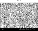
【図11】 ガラス板の上にパターン化されたゼオライト-A単層膜のSEM写真(倍率:5000倍)であり、ゼオライト単層膜の部分を大きく拡大したものである。
【図12】 ガラス板の上にパターン化されたゼオライトZSM-5二層膜のSEM写真(倍率:100倍)であり、実施例13(紫外線)の方法に従って製造したものである。
【図13】 ガラス板の上にパターン化されたゼオライトZSM-5二層膜のSEM写真(倍率:40000倍)であり、実施例13(紫外線)の方法に従って製造したものである。
【図14】 ガラス板の上にパターン化されたゼオライトZSM-5二層膜のSEM写真(倍率:60000倍)であり、実施例13(紫外線)の方法に従って製造したものである。
【図15】 ガラス板の上にパターン化されたゼオライトZSM-5多層膜のSEM写真(倍率:70000倍)であり、多層膜の断面を示している。
【図16】 ガラス板の上にパターン化されたゼオライトZSM-5多層膜のSEM写真(倍率:70000倍)であり、多層膜の断面を示している。[0001]
BACKGROUND OF THE INVENTION
The present invention relates to a patterned monolayer or multilayer composite of zeolite or zeotype molecular sieve and a method for producing the same. Specifically, the present invention relates to a substance having a hydroxy group on the surface, a thiol group (—SH) or an amino group (—NH2) And a substrate selected from a polymer having a reactive functional group, and then linking the linking compound to the substrate surface, and then selectively irradiating with ultraviolet light or By selectively applying a connecting compound or a shielding compound such as octadecyltrichlorosilane to the surface, or by selectively applying a metal such as platinum to a part of the substrate surface by vapor deposition, the connecting compound is bonded. A patterned monolayer or multilayer composite of a zeolite or similar molecular sieve, which is constructed by casting a pattern of a linking compound onto a substrate surface and selectively binding a zeolite or similar molecular sieve according to said pattern And a composite produced in this manner.
[0002]
[Prior art]
Diverse molecular sieves, including zeolites, are important substances that are used very widely in real life and industry. Since such zeolite particles are usually present in a fine powder, there are advantages in use, but there are many disadvantages. When such zeolite particles are firmly bonded to various substrates by chemical bonds, they have various industrial utility. In addition, adjusting the molecular sieving particles so as to have a certain orientation with respect to the substrate also has a great meaning because new physical properties can be expected. Furthermore, if there is a method that can selectively bind zeolite to the substrate surface, new characteristics that cannot be found from existing materials can be expected. In addition, if the molecular sieve particles can be adjusted to have a certain orientation with respect to the substrate, a breakthrough development can be achieved in the field of new materials.
[0003]
Zeolite is a generic term for crystalline aluminosilicate, and the framework aluminosilicate is negatively charged everywhere there is aluminum, so cations for charge cancellation are contained in the pores. The remaining space in the pores is usually filled with water molecules. The three-dimensional pore structure of zeolite varies depending on the shape and size, but the pore diameter usually corresponds to the size of the molecule. Therefore, zeolite is also called a molecular sieve because it has shape selectivity depending on the size and shape of the pores.
[0004]
Such zeolites exhibit various chemical and physical properties depending on chemical compositions and structures, pretreatment methods, and the like. In particular, zeolites in which hydrogen ions are replaced by cations are widely used as crude oil crekting catalysts in the petrochemical industry because they are combined with the characteristics of zeolites that can withstand high temperatures. In addition, zeolite is used in a wide range of dehydration desiccants, adsorbents, gas purifiers, ion exchangers, detergent additives, soil conditioners, and research on application as sensor carriers is actively underway.
[0005]
On the other hand, instead of silicon (Si) and aluminum (Al), which are the elements that form the framework structure of zeolite, zeolite-like molecular sieves (Zeotype molecular sieves) in which these elements are partially or wholly substituted with other elements are known. ing. For example, porous silica from which aluminum has been completely removed (MCM-series mesoporous silica and silicalite, etc.) and Alpo (AlPO) in which silicon is replaced by phosphorus (P)Four) System molecular sieves, and similar molecular sieves obtained by substituting various metal elements such as Ti, Mn, Co, Fe, and Zn in the framework of such zeolites and similar molecular sieves are widely known and widely applied. Has been.
[0006]
In order to make more effective use of the properties of such zeolites and similar molecular sieves, research for attaching zeolites to the surface of substrates such as glass, ceramics, polymers, metals, etc. has been actively conducted. [Reference: LCBoudreau, JA Kuck, M. Tsapatsis, J. Membr. Sci. 1999, 152, 41-59; Z. Li, C. Lai, TEMallouk, Inorg. Chem. 1989, 28, 178-182; LCBoudreau, JAKuck, M. Tsapatsis, J. Membr. Sci. 1999, 152, 41-59; JCJansen, D. Kashchiev, A. Erdem-Senatalar, Stud. Surf. Sci. Catal. 1994, 85, 215 -250; R. Althoff, K. Unger, F. Schuff, Microporous Mater. 1994, 2, 557-562].
[0007]
However, in the existing method, it is difficult to completely adjust the thickness and orientation of the zeolite monolayer film, and the present inventors use a linking compound having reactive functional groups on the substrate and the zeolite, respectively. A patent application was filed for the development of a simple and economical method for producing a substrate-linked compound-zeolite complex by chemically deforming the surface of the substrate and zeolite (Reference: Korean Patent Application No. 2000-19667) .
[0008]
On the other hand, many studies have already been conducted on a method of casting a pattern on the surface of a substrate such as glass, ceramic, polymer, and metal. Existing known pattern casting methods can be roughly divided into three. The first is a method of selectively casting a pattern using a photomask when irradiating ultraviolet rays. The second method is to take a template in advance using polydimethylsiloxane (PCMS), attach a shielding compound such as octadecyltrichlorosilane or a linking compound, and press the stamp on the substrate. . The third is a method in which a patterned metal grid is brought into close contact with a substrate, and a vapor deposition film of a metal such as platinum is selectively attached thereto to mold a pattern.
[0009]
As described above, it is a well-known technique to mold a pattern on the surface of the substrate so that the surface has different chemical reactivity depending on the pattern carved on the surface of the substrate. However, it is technically difficult to chemically bond the particles to the substrate surface by deforming the surface of particles such as zeolite so as to have chemical reactivity.
[0010]
[Problems to be solved by the invention]
The present inventors have made great progress on the procedure so that a chemical reaction in a solution state that has been known in the art is selectively performed on the surface of the object. In addition, extensive research has been conducted to produce various composites through the method thus developed.
[0011]
As a result, a pattern is cast using ultraviolet light (UV), a shielding compound and metal deposition (eg platinum) on the substrate, and the patterned substrate surface thus obtained is subjected to a chemical reaction through a chemical reaction. Attempts were made to produce patterned zeolite monolayers and multilayers by bonding and to increase the durability and orientation of such composites.
[0012]
As described above, the surface of the substrate differs according to the pattern by casting the pattern on the substrate surface using ultraviolet (UV), a connecting compound or a shielding compound (eg, octadecyltrichlorosilane) and metal (eg, platinum) deposition. It is a well-known process to deform to have chemical reactivity, but it has been known to date to form a patterned zeolite layer on the surface of this surface-modified substrate. Never before.
[0013]
However, as described above, when using the method described in Patent Application No. 2000-19667 filed by the present inventors, that is, a method in which a zeolite is bonded onto a substrate through a chemical bond mediated by a linking compound, a pattern is used. Zeolite layer can be easily laminated according to the above pattern on the substrate on which is molded, and not only single layer but also multilayer lamination is possible, and each layer has various pattern forms and materials (types of molecular sieve) I found out that it can be adjusted.
[0014]
[Structure of the invention]
The present invention relates to a method for producing a composite comprising a substrate-linked compound-zeolite or a similar molecular sieve, a substance having a hydroxy group on the surface, a thiol group (-SH) or an amino group (-NH2A substrate selected from a polymer capable of reacting with a reactive polymer and a polymer having a reactive functional group, and then selectively irradiating with ultraviolet light after binding the linking compound to the substrate surface, or a part of the substrate surface By selectively applying a linking compound or a shielding compound such as octadecyltrichlorosilane to the substrate, or by selectively applying a metal such as platinum to a part of the substrate surface by vapor deposition, the linking compound is bonded. Patterned monolayers and multilayer composites of zeolites or similar molecular sieves constructed by casting a pattern of linking compounds onto the substrate surface and selectively binding zeolite or similar molecular sieves according to said patterns and It relates to a manufacturing method thereof.
[0015]
Accordingly, a first object of the present invention is to provide a method for producing a complex comprising a substrate-linking compound-zeolite or a similar molecular sieve, in which (i) a linking compound is bound to the substrate surface, and (ii) a light having a pattern. Using a mask, the substrate is UV-irradiated to modify the linking compound or its functional group bound to the substrate, and (iii) a zeolite layer or similar to the UV-irradiated or non-UV-irradiated portion A method for producing a patterned monolayer or multilayer composite of a zeolite or similar molecular sieve, characterized in that it is formed by selectively forming a molecular sieve layer and (iv) firing as necessary. Is to provide.
[0016]
Further, in the first target production method, after removing the UV-irradiated part or the non-UV-irradiated part, a layer made of zeolite or a similar molecular sieve can be formed.
[0017]
A second object of the present invention is a method for producing a composite comprising a substrate-linking compound-zeolite or a similar molecular sieve, wherein (i) the linking compound or the shielding compound is formed on a part of the substrate surface so as to have a predetermined pattern. (Ii) a shielding compound or a linking compound is bonded to the remaining substrate surface, and (iii) a zeolite layer or a similar molecular sieve layer is selectively formed on the portion where the linking compound is bonded, (Iv) To provide a method for producing a patterned monolayer or multilayer composite of zeolite or a similar molecular sieve, which is constituted by calcining as necessary.
[0018]
In the second objective manufacturing method, a linking compound or a shielding compound can be applied to a part of the substrate surface by a stamp method.
[0019]
A third object of the present invention is to provide a composite comprising a substrate-linking compound-zeolite or similar molecular sieve, and (i) a metal film such as platinum so as to have a predetermined pattern on a part of the substrate surface. And (ii) forming a zeolite or similar molecular sieve layer by crystal growth in the remaining part, or forming a zeolite layer or similar molecular sieve layer by combining zeolite (or similar molecular sieve) -linking compound. And (iii) to provide a method for producing a patterned monolayer or multilayer composite of zeolite or a similar molecular sieve, which is constituted by calcining as necessary.
[0020]
The fourth object of the present invention is to provide a patterned monolayer or multilayer composite of zeolite or similar molecular sieve produced according to the above production method, and in each layer of zeolite or similar molecular sieve. Types and types and pattern patterns are the same or different.
[0021]
Hereinafter, the present invention will be described more specifically.
[0022]
1. Substrate type and range
The substrate used in the present invention is as follows.
All substances having a hydroxyl group on the surface: for example, oxides containing various metals and nonmetallic elements such as silicon, aluminum, titanium, tin, and indium alone or in combination, such as quartz, mica, glass, ITO glass (glass with deposited indium tin oxide), tin oxide (SnO2) Etc., various conductive glass, silica, porous silica, alumina, porous alumina, titanium dioxide, porous titanium dioxide, silicon wafer and the like.
Metals capable of binding to a thiol group or amino group: for example, gold, platinum, silver, copper and the like. Polymers having various functional groups on the surface: For example, polymers such as PVC and Merrifield peptide resin.
Semiconductor: For example, selenium zinc (ZnSe), gallium arsenide (GaAs), indium phosphide (InP), and the like.
Natural polymers having a hydroxyl group on the surface: for example, cellulose, starch (eg, amylose and amylopectin) and lignin.
Natural or synthetic zeolites and similar molecular sieves as defined below
[0023]
2. Types and ranges of molecular sieves
The molecular sieves that can be used in the present invention are as follows.
(1) Natural and synthetic zeolites.
(2) Molecular sieves in which all or part of the silicon element of the zeolite framework is replaced with other elements such as phosphorus (P) (eg, AlPOFour, SAPO, MeAPO, MeAPSO and other molecular sieves).
(3) A molecular sieve in which the aluminum element of the zeolite skeleton is partially or completely substituted with other elements such as boron (B), gallium (Ga), and titanium (Ti).
(4) A molecular sieve combining the changes in the above 2 and 3 terms.
(5) Porous metal or silicon oxide (eg, silicalite, MCM-based porous silica, porous titanium dioxide, niobium dioxide, etc.) and complex oxides thereof.
(6) Porous molecular sieves produced using other various elements alone or in combination.
[0024]
3. Types and scope of linking compounds
In the present invention, the linking compound means a compound having functional groups capable of chemically bonding to a substrate or zeolite at both ends. The functional group capable of chemically bonding to the substrate or the zeolite refers to a trichlorosilyl group (-SiCl) that can bond by reacting with a hydroxyl group for zeolite and glass having a surface hydroxyl group.Three) And trimethoxysilyl group (-Si (CHThree)Three) Or isocyanato group (-N = C = O), and for substrates such as gold, a thiol group. When these functional group-bound compounds react with a substrate, it is known that self-assembled monolayers (SAMs) can be formed on the surface of the substrate.
[0025]
Of course, depending on the surface properties of the substrate (functionality), it is possible to select an appropriate functional group that can chemically bond with it, and such functional groups have common knowledge in the art. It can be appropriately selected by technicians.
[0026]
Linking compounds that can be used in the present invention desirably include compounds of formulas 1-6:
RThreeSi-L-X (1)
MR´Four (2)
Y-L-Y (3)
RThreeSi-L-Y (4)
HS-L-X (5)
HS-L-SiRThree (6)
HS-L-Y (7)
(From the above formula, R is a halogen group element, C1-CFourIndicates an alkoxy or alkyl group; L is a hydrocarbon residue, eg substituted or unsubstituted C1-C17Represents an alkyl, aralkyl or allyl group, which may contain one or more oxygen, nitrogen, sulfur atoms; X represents a leaving group such as halogen, provided that at least one of the three R One is halogen or alkoxy; R ′ is the same as R; at least two of the four R ′ are halogen or alkoxy; M is Si, Ti or Zr; Y is a hydroxyl group, thiol Group, amine group, ammonium group, sulfone group and salt thereof, carboxylic acid and salt thereof, acid anhydride, epoxy group, aldehyde group, ester group, acrylic group, isocyanate group (-NCO), saccharides residue Ligand exchange including well-known organic functional groups such as group, double bond, triple bond, diene, diyne, alkylphosphine, alkylamine Shows reactivity functional group such as various coordination compounds may Rukoto, provided that the reactive functional group may also be located in the middle rather than at both ends of the linking compound molecule. )
[0027]
The linking compound bonded to the substrate and the zeolite may have one or more chemical functional groups in the linking compound skeleton in order to form a secondary chemical bond. For example, a linking compound bonded to a substrate contains a formyl group (—CHO) in its molecule, and a linking compound attached to the zeolite surface has an amino group (—NH) in its molecule.2), A chemical reaction easily occurs between the amino group and the formyl group, so that the zeolite can be chemically bonded to the substrate by the coupling compound-linking compound bond.
[0028]
As described above, the coupling compound-linking compound bond can also be mediated by other linking compounds or bifunctional compounds, for example, the following mediating compounds:Fullerene(C60, C70), Carbon nanotube, Α, ω-dialdehyde, dicarboxylic acid, dicarboxylic acid anhydride, amine-dendrimer, polyethyleneimine, α, ω-diamine, wearing compound [M (salen)] (wherein M is Co, Ni, Cr) , Mn and Fe, and salen is N, N′-bis (salicylidene) ethylenediamine), one or more compounds selected from metal porphyrin.
[0029]
In summary, the linking compound has one functional group capable of chemically reacting with the substrate and one functional group capable of chemically reacting with other zeolites or other linking compound functional groups bound to the particle surface thereof. That is, it must have at least two functional groups. The linking compounds and the functional groups and their combinations are infinitely variable and can be easily changed or combined as necessary by an engineer having ordinary knowledge in the art as necessary. When the concept is used, it is included in the scope of the present invention.
[0030]
4). Chemical reaction between substrate or molecular sieve and linking compound
Substrates such as glass and molecular sieves have a hydroxyl group on the surface as described above, and thus react with a linking compound having an appropriate functional group capable of reacting with the hydroxyl group to react with the substrate-linking compound or linking compound. -A complex of molecular sieves can be formed. In addition, since a single functional group can be modified or transformed into a new functional group by appropriate treatment, the surface of a substance having appropriate functionality may have new functionality through chemical treatment. Can be transformed into Such reactions and reaction conditions are well known in the art.
[0031]
Metals such as gold do not have a hydroxyl group on the surface, but they have very good reactivity with thiol groups, so they can be easily combined with linking compounds that have a thiol group introduced at one end. A compound having a thiol group at one end can be used as a linking compound or a shielding compound for a gold substrate.
[0032]
The substrate or molecular sieve particles are placed in a reaction vessel containing an organic solvent such as toluene, and the linking compound is added and heated. Here, instead of toluene, other generally well-known organic solvents such as hexane, benzene, carbon tetrachloride, alcohol and the like can be appropriately used for the reaction. When the reaction is complete, the substrate is removed and washed thoroughly with toluene. In this way, when a chemical bond is formed on the surface of the molecular sieve, the chemical bond may be caused to occur directly by using an organic compound vapor. The molecular sieve in the dispersion is filtered using filter paper and washed thoroughly with an organic solvent. At this time, if the molecular sieve particles are too small to use the filter paper, the particles are separated using a centrifuge. The molecular sieve crystals are placed in a reaction vessel containing toluene and well dispersed using an ultrasonic washer. It is also possible to evaporate these compounds without a solvent under vacuum and vacuum to bind to a substrate or molecular sieve.
[0033]
5. Method of casting a pattern on the substrate surface
There are various methods for casting a pattern template on the substrate surface. In the present invention, the following three methods were used. In the present invention, pattern formation means that the zeolite or similar molecular sieve is selectively reacted or shielded from selective reaction. The method of the present invention is not limited to the following three methods, and all of these modified methods and methods that provide the same effect do not depart from the scope of the present invention.
[0034]
The first is a method of modifying the linking compound using ultraviolet rays (UV).
[0035]
The substrate to which the linking compound is bonded is irradiated with ultraviolet rays (UV; λ = 254 nm) for an appropriate time by applying a photomask having a pattern on it. At this time, in the region exposed to ultraviolet rays, the functionality of one end of the linking compound bonded to the surface is deformed. And in the area | region which is not exposed to an ultraviolet-ray, the functionality is maintained as it is. Therefore, the chemical functionality of the substrate surface varies depending on the pattern form. The change in functionality due to UV irradiation can be reversed.
[0036]
The second is a method of microcontacting the shielding compound or linking compound directly to the substrate.
[0037]
In the present invention, the shielding compound has a functional group capable of reacting with a substrate, unlike a linking compound having functional groups at both ends, but can react with a molecular sieve or other linking compound at one side terminal. A compound without a functional group, for example trialkoxyalkylsilane (RSi (OR)Three, R = alkyl) or trichloroalkylsilane (RSiClThree, R = alkyl). In the shielding compound described above, the alkyl group is C6Above, preferably CTenThe long chain is desirable.
[0038]
After applying a hexane solution in which octadecyltrichlorosilane (OTS) of a PDMS (polydimethylsiloxane) stamp with a pattern is dissolved, OTA is installed in a spin coater. Rotate the PDMS stamp to evenly distribute the octadecyltrichlorosilane on the stamp and press the stamp on the glass plate. The glass plate is left at room temperature for 1 hour or more and then dried at 120 ° C. for 5 minutes. Octadecyltrichlorosilane reacts with glass silanol to form an octadecyl monolayer according to the pattern. That is, an octadecyl monolayer is formed in the area where the stamp is touched on the glass surface, and the silanol on the glass surface remains as it is in the area where the stamp is not touched. When the surface of the glass plate on which the octadecyl group is patterned in this way is treated with the connecting compound as described above, the region where the octadecyl group is previously bonded remains as it is, and the hydroxyl group (—OH) on the glass surface remains. ) The linking compound binds only in a certain region and can have a new functionality. Therefore, there is a difference in chemical functionality depending on the pattern form.
[0039]
The third is a method of shielding the metal-deposited surface by depositing a part of the surface with a non-reactive metal. All metals generally used for chemical vapor deposition can be used, and platinum vapor deposition is used in the present invention, but the present invention is not limited thereto.
[0040]
Similar to the method using ultraviolet rays, a mask on which a pattern is cast is applied on the substrate, and platinum is deposited to a thickness of about 15 nanometers (nm) using a vacuum heating deposition apparatus. The region contacted by the mask has the functionality of the substrate as it is without vapor deposition of platinum, and the exposed region has the functionality of platinum because platinum is vapor deposited. Therefore, it can be templated to have different chemical functionalities on the substrate surface.
[0041]
6). Form patterned zeolite monolayer and multilayer on substrate surface
Method
When a substrate patterned with different chemical functionality is chemically bonded to the zeolite particles, the zeolite is joined in the patterned form due to the difference in functionality. Patterned zeolite monolayer composites are simply physically attached with zeolite particles during their manufacturing process. In this case, the physically attached zeolite particles can be removed by ultrasonic cleaning.
[0042]
A patterned zeolite multilayer composite can be easily produced by repeating the above-described methods. That is, when zeolite particles having a functional group capable of chemically reacting with a functional group of a linking compound bonded to a patterned zeolite monolayer membrane are treated again, a bilayer membrane is formed, and this process is repeated. Thus, a desired patterned zeolite multilayer membrane composite can be produced.
[0043]
In the multilayer composite, the zeolite or similar molecular sieve constituting the upper layer and the lower layer are the same or different, and the patterns constituting the upper layer and the lower layer are the same or different.
[0044]
【Example】
Hereinafter, the present invention will be described in more detail with reference to examples.
[0045]
Example 1: Pretreatment of substrate
A substrate such as glass or silicon wafer is placed in about 10% hydrochloric acid solution and heated for 1 hour or more, or ammonium persulfate ((NHFour)2S2O8) And sulfuric acid solution for at least one hour. The substrate is taken out, washed thoroughly with distilled water, soaked in ammonia water for 15 minutes, and further immersed in acetic acid for about 30 minutes. Store in distilled water and dry before use.
[0046]
Example 2: Manufacture of a metal plate
First, titanium or chromium is vacuum heated and deposited to a thickness of about 100 mm on a substrate such as glass or silicon wafer. Gold is deposited on the titanium or chromium layer to a thickness of about 1000 mm using a vacuum heating deposition method. Wash with a piranha solution mixed with sulfuric acid and hydrogen peroxide in a 7: 3 ratio, then heat and cool under vacuum at 300 ° C for 3 hours just before use.
[0047]
Example 3: UV ( UV Λ = 254nm Of a zeolite monolayer film patterned through chemical ionic bonding on top of a pattern manufactured using
Glass plate with (3-cyanopropyl) trichlorosilane (ClThreeSi- (CH2)ThreeImmerse in hexane (50 ml) solution containing -CN; 0.05 ml) and let stand at room temperature for 24 hours. Remove the glass plate with 3-cyanopropyl group attached and place in a flask containing concentrated hydrochloric acid and heat at 95-100 ° C for 2 hours. The cyano group is converted to carboxylic acid through hydrolysis. Glass plate with carboxylate group [Glass- (CH2)Three-CO2H] and sodium bicarbonate (NaHCOThree) Soak in saturated aqueous solution for 12 hours. Hydrogen ions are replaced with sodium ions through the neutralization reaction (CH2)Three-CO2 -・ Na+A glass plate to which groups are bonded can be obtained. This is 1M silver nitrate (AgNOThree) Soak again in aqueous solution for 12 hours. Sodium ion is replaced with silver ion through ion exchange (CH2)Three-CO2 -・ Ag+A glass plate to which groups are bonded can be obtained.
[0048]
-(CH2)Three-CO2 -・ Ag+The substrate is irradiated with ultraviolet rays (UV; λ = 254 nm) for about 1 hour by applying a photomask having a pattern engraved on the glass plate to which the group is bonded. Silver ions bonded to the portion exposed to the ultraviolet light are reduced to silver, and silver ions remain in the unexposed portion. Therefore-(CH2)Three-CO2 -・ Ag+A glass plate with a patterned base can be obtained.
[0049]
Zeolite particles are placed in a reaction vessel containing toluene, and 3-aminopropyltriethoxysilane (APS) is added and heated. When the reaction is completed, the zeolite to which the 3-aminopropyl group is bonded is filtered and washed well with toluene and ethanol. Zeolite with a 3-aminopropyl group bonded to sodium bicarbonate and iodomethane (CHThreePut in a 90% ethanol solution in which I) is dissolved and stir at 60 ° C for 24 hours. -(CH2)Three-N (CHThree)Three +・ I-The zeolite to which the group is bonded is filtered through a filter paper and then washed with ethanol and distilled water.
[0050]
(CH2)Three-N (CHThree)Three +・ I-After the group-bound zeolite is placed in a reaction vessel containing ethanol and well dispersed (CH2)Three-CO2 -・ Ag+A glass plate on which the groups are patterned and bonded is immersed. Raise the temperature to 60 to 78 ° C, leave it for 10 minutes, and intermittently vibrate using an ultrasonic washer. A patterned zeolite monolayer can be produced by removing the glass plate, placing it in a glass bottle containing toluene, and applying ultrasonic vibration to simply remove the zeolite physically attached to the monolayer. .
[0051]
The above production method can produce a zeolite single layer film similarly patterned even if a metal plate is used. However, when using a metal plate, one side end of the organic molecule bound to the metal plate is a trichlorosilyl group (-SiClThree) Or trialkoxysilyl groups (-Si (OR)ThreeIt must have a thiol (—SH) group instead of R = methyl or ethyl. The reason is that only the thiol group can be strongly bonded to the gold surface.
[0052]
Example 4: Ultraviolet rays ( UV Manufacturing of patterned zeolite monolayer film through chemical covalent bond on the pattern manufactured using mercury photogen
Place the glass plate in a reaction vessel containing toluene and add (3-iodopropyl) trimethoxysilane. After heating for 3 hours, the glass plate is thoroughly washed with toluene.
[0053]
When a glass plate to which 3-iodopropyl groups are bonded is subjected to the UV patterning process mentioned in Example 3, the portions exposed to UV light are decomposed by iodo groups and the portions not exposed to 3-iodopropyl groups are exposed to 3-iodopropyl groups. A patterned glass plate remaining as it is can be obtained.
[0054]
After the zeolite is placed in a reaction vessel containing toluene and well dispersed, a glass plate on which 3-iodopropyl groups are patterned and bonded is immersed. Heat for 3 hours, take out the glass plate, and put it in a glass bottle containing toluene. A patterned zeolite monolayer membrane can be produced by removing the zeolite that is physically attached to the monolayer membrane by ultrasonic vibration.
[0055]
Example 5: UV light ( UV Manufacturing of patterned zeolite monolayer film through covalent bond on the pattern manufactured using mercury photogen)
Place the glass plate in a reaction vessel containing toluene and add 1,4-diisocyanate butane. After heating for 3 hours, the glass plate is thoroughly washed with toluene. One of the two isocyanate groups reacts with the glass plate to form a urethane bond, and the other isocyanate groups remain on the glass surface in an unreacted state.
[0056]
When the glass plate to which the isocyanate group is bonded is subjected to the ultraviolet pattern process referred to in Example 3, the portion exposed to the ultraviolet ray is decomposed by the urethane group, and the portion not exposed by the urethane bond remains as it is. A patterned glass plate can be obtained.
[0057]
After the zeolite is placed in a reaction vessel containing toluene and well dispersed, a glass plate on which isocyanate groups are patterned and bonded is immersed. Heat for 3 hours, take out the glass plate and put it in a glass bottle containing toluene. A patterned zeolite monolayer membrane can be produced by removing the zeolite that is physically attached to the monolayer membrane by ultrasonic vibration.
[0058]
Example 6: UV light on a metal plate ( UV Manufacturing of patterned zeolite monolayer film through chemical covalent bond on the pattern manufactured using mercury photogen
1-mercapto-11,13-pentacosadinic acid [1-mercapto-11,13-pentacosadiynoic acid; HS (CH2)TenC≡C-C≡C (CH2)11Immerse the gold plate in 1 mM chloroform solution of [COOH] for 24 hours, then remove it and wash with chloroform. When the ultraviolet pattern process mentioned in Example 3 is performed in a nitrogen environment, a polymerization reaction occurs in the monomolecular layer bonded to the portion exposed to the ultraviolet rays to form a network between the molecular chains. Removal of the portions of self-assembled monolayers (SEMs) that are not exposed to ultraviolet light can provide patterned metal plates in which organics are selectively bonded onto the metal plate.
[0059]
In general, a method for removing thiol from a gold surface is used as a method for removing a portion not exposed to ultraviolet rays. For example, the following three methods are typical:
The first is an electrochemical reduction method;
The second is a method through heat treatment;
The third method uses a corrosive solvent.
[0060]
The method for attaching and detaching the thiol compound from the gold surface is well known in the art.
[0061]
A suitable organic solvent (eg, toluene or dichloromethane) in which a coupling agent such as dicyclohexylcarbodiimide (DCC) and a base catalyst such as 4-dimethylaminopyridine (DMAP) are dissolved. Then, a well-dispersed zeolite prepared in Example 3 and having a 3-aminopropyl group bonded thereto was dispersed, and a patterned gold plate was placed therein and heated at 80 ° C. for 48 hours. When a metal plate is taken out and placed in a glass bottle containing toluene and subjected to ultrasonic vibration to simply remove the physically attached zeolite, a patterned zeolite monolayer film can be produced.
[0062]
The coupling agent can be replaced with other coupling agents commonly used in the industry.
[0063]
In addition, since the zeolite can bind to the substrate through a chemical reaction between the carboxylic acid group of the substrate and the amino group of the zeolite, the carboxylic acid of the substrate can be activated to facilitate the chemical reaction with the amino group. Zeolite monolayer films patterned on a metal plate can be produced. As an example, a patterned gold plate is treated with trifluoroacetic anhydride [(CFThreeCO)2Immerse in a dimethylformamide solution in which O] and triethylamine are dissolved for 20 minutes. The end of the metal plate surface is carboxylic acid (R-COOH) to acetoacetic acid trifluoroacetic anhydride (R-COOCOCFThreeSuch a form facilitates reaction with the amino group as an activated state of the carboxylic acid. The metal plate is taken out, washed with an organic solvent, and immersed in toluene in which a zeolite to which a 3-aminopropyl group is bonded is dispersed. When the reaction is allowed to proceed for 48 hours at room temperature, the metal plate is taken out, immersed in a glass bottle containing toluene, and then subjected to ultrasonic vibration to remove the zeolite physically attached on the monolayer film, as described above. Zeolite monolayer films patterned on a metal plate can be produced.
[0064]
Example 7: UV light ( UV Production of patterned zeolite monolayers by direct growth of zeolite crystals on top of patterns produced using mercury photogens)
The procedure is the same as that described in Examples 3 and 4, except that 3-aminopropylmethyldiethoxysilane, propyltrimethoxysilane, 3-iodopropyltrimethoxy are used as the organic silane compounds. Using silane ((3-iodopropyl) trimethoxysilane) or 3-aminopropyltriethoxysilane ((3-aminopropyl) triethoxysilane), 3-aminopropylmethyl group, propyl group, 3-iodopropyl group and 3-amino group respectively A glass plate to which a propyl group is bonded is produced.
[0065]
As mentioned in Example 3, a glass mask bonded with organosilane is irradiated with ultraviolet rays by applying a photomask having a pattern engraved thereon. The irradiation time varies depending on the type of organosilane, and is preferably about 10 minutes to 1 hour. Decomposition occurs in the part exposed to ultraviolet rays. Therefore, a glass plate on which the organosilane layer is patterned can be obtained.
[0066]
The patterned glass plate is placed in a zeolite synthesis gel and the zeolite is grown directly on the glass plate. Direct growth of crystal of the zeolite will occur only in the part exposed to UV light. Thus, a patterned zeolite monolayer film can be obtained by selective crystal growth on the glass surface. As an example, the preparation process of ZSM-5 zeolite growth gel is as follows. First, tetrapropylammonium hydroxide (TPAOH) is dissolved in water as a zeolite template, and tetraethylorthosilicate as a silicon source (source). Add tetraethyl orthosilicate (TEOS) and stir until a homogeneous liquid is obtained. To this, sodium aluminate is added as an aluminum source and stirred until a homogeneous liquid is obtained. The final gel composition is SiO2: Al2OThree: TPAOH: Na2O: H2O = 0.1-1: 0-0.035: 0.1: 0-0.017: 20-150. The synthetic gel and the patterned glass plate thus obtained are placed in a pressure reactor (autoclave), and the reaction is allowed to proceed at 120 to 180 ° C. for 3 to 12 hours. When a glass plate is taken out and placed in a glass bottle containing toluene and subjected to ultrasonic vibration to remove zeolite physically attached on the monolayer film, a patterned zeolite monolayer film can be produced.
[0067]
When the synthetic gel is made different depending on the kind of zeolite, variously patterned zeolite monolayer films can be obtained, and the production of zeolite synthetic gel is well known in the art.
[0068]
Example 8: Fabrication of a patterned zeolite monolayer through chemical covalent bonds on top of a pattern produced using chemicals
[0069]
[Formula 1]
A hexane solution in which octadecyltrichlorosilane (OTS) is dissolved is applied to a stamp that has been patterned with PDMS (polydimethylsiloxane), and then attached to a spin coater. Rotate the PDMS stamp to evenly distribute the octadecyltrichlorosilane on the stamp and press the stamp on the glass plate.
[0071]
The glass plate is left at room temperature for 1 hour or more and then dried at 120 ° C. for 5 minutes. Octadecyltrichlorosilane reacts with glass silanol to form an octadecyl monolayer in the form of a pattern. That is, an octadecyl monomolecular layer is formed in the area where the stamp touches the glass surface, and the silanol on the glass surface remains as it is in the non-touching portion.
[0072]
The thus obtained octadecyl group-patterned glass plate is placed in a reaction vessel containing toluene and (3-chloropropyl) trimethoxysilane is added. Heating for 3 hours and washing the glass plate with toluene yields a glass plate patterned with octadecyl groups and 3-chloropropyl groups.
[0073]
A glass plate on which octadecyl groups and 3-chloropropyl groups are patterned is immersed in toluene in which zeolite is dispersed, and heated for 12 hours. The glass plate is taken out and placed in a glass bottle containing toluene, and subjected to ultrasonic vibration to remove the physically attached zeolite.
[0074]
Example 9: Fabrication of a patterned zeolite monolayer by direct growth of zeolite crystals on top of a pattern produced using chemicals
According to the procedure described in Example 8, a glass plate on which an octadecyl group monolayer is patterned is manufactured using a stamp in which a pattern is cast as PDMS (polydimethylsiloxane).
[0075]
As described in Example 7, a glass plate patterned with octadecyl groups is placed in a pressure reactor containing a zeolite synthesis gel to allow direct growth of crystal of the zeolite on the glass surface. . A zeolite crystal is formed and grows only at a portion where the octadecyl group is not bonded, thereby producing a patterned zeolite monolayer film.
[0076]
Example 10: Fabrication of a patterned zeolite monolayer through chemical covalent bonding on a pattern produced using platinum deposition
On the glass plate, a mask on which a pattern is cast is applied, and platinum is deposited to a thickness of about 15 nm using a vacuum heating deposition apparatus. Platinum is not deposited on the portion shielded by contact with the mask, and platinum is deposited on the exposed portion. The glass plate on which the platinum pattern is thus engraved is subjected to the process described in Example 8 to obtain a glass plate on which platinum and 3-chloropropyl groups are patterned, and a patterned zeolite monolayer film is obtained. Manufacturing.
[0077]
According to the procedure as described in Example 4, first, a glass plate to which a 3-chloropropyl group is bonded is prepared, and a pattern made of a platinum vapor deposition film is cast as a template to form a similarly patterned zeolite monolayer film. Could be manufactured.
[0078]
Example 11: Fabrication of a patterned zeolite monolayer by direct growth of zeolite crystals on top of a pattern produced using platinum deposition.
According to the procedure as described in Example 10, a platinum pattern is carved on a glass plate using a platinum vapor deposition method. This glass plate is placed in a zeolite synthesis gel according to the procedure described in Example 7 to grow crystals. Crystal growth occurs only in the parts where platinum is not engraved.
[0079]
Example 12: UV light ( UV A patterned zeolite bilayer membrane through a chemical ionic bond on top of a pattern produced using bilayer )Manufacturing of
According to the procedure as described in Example 3, first a glass plate on which a patterned zeolite monolayer film is formed is produced.
[0080]
Separately-(CH2)Three-CO2 -・ Na+After the zeolite to which the group is bonded is produced and dispersed in toluene, the glass plate on which the zeolite monolayer film is patterned is immersed. Raise the temperature to 60 to 78 ° C, leave it for 10 minutes, and intermittently vibrate using an ultrasonic washer. Take out the glass plate, immerse it in a glass bottle containing toluene, and then ultrasonically vibrate to remove the zeolite that is physically attached on the bilayer membrane to produce a patterned zeolite bilayer membrane To do.
[0081]
Example 13: UV light ( UV A patterned zeolite bilayer membrane through a chemical covalent bond on top of a pattern produced using mercury photogen. bilayer )Manufacturing of
According to the procedure as described in Example 4, a glass plate with a patterned zeolite monolayer film is produced.
[0082]
Separately, a zeolite to which a 3-iodopropyl group is bonded is manufactured and dispersed in toluene, and then a glass plate on which a zeolite monolayer film is patterned is immersed. Heat for 3 hours, take out the glass plate and put it in a glass bottle containing toluene. Ultrasonic vibration is used to remove the zeolite that is simply physically attached on the bilayer membrane to produce a patterned zeolite bilayer membrane.
[0083]
Example 14: Fabrication of a patterned zeolite bilayer film through a chemical covalent bond on a pattern produced using platinum deposition
According to the procedure as described in Example 9, a glass plate with a patterned zeolite monolayer film is produced.
[0084]
Separately, a zeolite to which a 3-iodopropyl group is bonded is produced and dispersed in toluene, and then a glass plate on which a zeolite monolayer film is patterned is immersed. Heat for 3 hours, take out the glass plate and put it in a glass bottle containing toluene. Ultrasonic vibration is used to remove the zeolite that is simply physically attached on the bilayer membrane to produce a patterned zeolite bilayer membrane.
[0085]
Example 15: Preparation of patterned zeolite multilayer membrane
According to the procedure as described in Example 12, a glass plate with a patterned zeolite bilayer membrane is produced.
[0086]
(CH2)Three-N (CHThree)Three +・ I-After the group-bound zeolite is placed in a reaction vessel containing ethanol and well dispersed, the glass plate on which the zeolite bilayer film is patterned is immersed. Raise the temperature to 60 to 78 ° C, leave it for 10 minutes, and intermittently vibrate using an ultrasonic washer. Remove the glass plate and place it in a glass bottle containing toluene. A patterned zeolite tri-layer is produced by ultrasonically removing the zeolite that is simply physically attached onto the bilayer membrane.
[0087]
When such a process is repeated, the number of layers of the zeolite multilayer film produced can be adjusted according to the number of repetitions. Moreover, a zeolite multilayer film can be manufactured by repeating the processes of Examples 13 and 14.
[0088]
Example 16: UV light ( UV Manufacturing of patterned composite zeolite monolayer on top of pattern manufactured using mercury photogen)
According to the procedure as described in Example 7, a glass plate with a patterned zeolite monolayer film is produced.
[0089]
The glass plate is calcined to remove organic substances in the portion where the zeolite has not grown (or bonded). The glass plate is again placed in a new zeolite synthesis gel to allow secondary crystal growth on the glass surface. If the ZSM-5 zeolite is first crystal-grown to obtain a zeolite pattern, then the zeolite-A crystal is secondarily grown to obtain a pattern of composite zeolite. This is possible because the rate of crystal growth in the zeolite synthesis gel is different between the glass surface and the zeolite surface.
[0090]
A combination of zeolite types different from those described above can also be used.
[0091]
Example 17: Scanning electron microscope ( scanning electron microscope ; SEM )analysis
SEM images were obtained using a scanning electron microscope (model; Hitachi S-4300) after applying a platinum / palladium coating to a zeolite monolayer film or multilayer film prepared according to the above-mentioned examples to a thickness of about 15 nm. . 1 to 16 show representative SEM images of various composites produced according to each example.
[0092]
【The invention's effect】
According to the present invention, a composite in which a porous molecular sieve such as zeolite is patterned with a single layer film and a multilayer film through chemical bonding can be produced. In addition to providing diversity in the bonding method by deforming the functional group at the substrate and molecular sieve ends, if necessary, the pattern form, the pattern form of each layer with a multilayer film, and the molecular sieve constituting the pattern Therefore, it is advantageous in terms of practicality.
Patterned molecular sieve monolayer and multilayer membrane composites produced in accordance with the present invention include gas and liquid separation membranes, linear and nonlinear optical devices, opto-electronics, membranes, membrane catalysts It can be usefully used for film formation using a sensor carrier, a photocell, a second growth of zeolite, and the like. In addition, new physical properties appearing when molecular sieve particles form a pattern are also expected. Therefore, such a new composite is expected to be effective as an innovative new material not only in academic terms but also in practical terms.
[Brief description of the drawings]
FIG. 1 is an SEM (scanning electron microscope) photograph (magnification: 30 times) of a zeolite ZSM-5 monolayer film patterned on a glass plate, manufactured according to the method of Example 8 (shielding compound). It is.
FIG. 2 is an SEM (scanning electron microscope) photograph (magnification: 30 times) of a zeolite ZSM-5 monolayer film patterned on a glass plate, which was produced according to the method of Example 8 (shielding compound). It is.
FIG. 3 is an SEM photograph (magnification: 30 times) of a zeolite ZSM-5 monolayer film patterned on a glass plate, which was produced according to the method of Example 4 (ultraviolet light).
FIG. 4 is an SEM photograph (magnification: 100 times) of a zeolite ZSM-5 monolayer film patterned on a glass plate, which was produced according to the method of Example 4 (ultraviolet light).
FIG. 5 is a SEM photograph (magnification: 100 times) of a zeolite ZSM-5 monolayer film patterned on a gold plate, which was produced according to the method of Example 6 (ultraviolet light).
FIG. 6 is an SEM photograph (magnification: 30 times) of a zeolite ZSM-5 monolayer film patterned on a glass plate, which was produced according to the method of Example 10 (platinum deposition).
FIG. 7 is an SEM photograph (magnification: 30 times) of a zeolite ZSM-5 monolayer film patterned on a glass plate, which was produced according to the methods of Examples 7 (ultraviolet rays) and 11 (platinum deposition). It is.
FIG. 8 is an SEM photograph (magnification: 180 times) of a zeolite ZSM-5 monolayer patterned on a glass plate, manufactured according to the methods of Example 7 (ultraviolet light) and 11 (platinum deposition). It is.
FIG. 9 is an SEM photograph (magnification: 800 times) of a zeolite ZSM-5 monolayer film patterned on a glass plate, which was produced according to the methods of Examples 7 (ultraviolet rays) and 11 (platinum deposition). It is.
FIG. 10 is an SEM photograph (magnification: 5000 times) of a zeolite ZSM-5 monolayer film patterned on a glass plate, which is a greatly enlarged portion of the zeolite monolayer membrane.
FIG. 11 is an SEM photograph (magnification: 5000 times) of a zeolite-A monolayer film patterned on a glass plate, which is a greatly enlarged portion of the zeolite monolayer membrane.
FIG. 12 is an SEM photograph (magnification: 100 times) of a zeolite ZSM-5 bilayer film patterned on a glass plate, which was produced according to the method of Example 13 (ultraviolet light).
FIG. 13 is an SEM photograph (magnification: 40000 times) of a zeolite ZSM-5 bilayer film patterned on a glass plate, which was produced according to the method of Example 13 (ultraviolet light).
FIG. 14 is an SEM photograph (magnification: 60000 times) of a zeolite ZSM-5 bilayer film patterned on a glass plate, which was produced according to the method of Example 13 (ultraviolet light).
FIG. 15 is an SEM photograph (magnification: 70000 times) of a zeolite ZSM-5 multilayer film patterned on a glass plate, showing a cross section of the multilayer film.
FIG. 16 is an SEM photograph (magnification: 70000 times) of a zeolite ZSM-5 multilayer film patterned on a glass plate, showing a cross section of the multilayer film.
Claims (15)
(i)基質表面に、作用基を両側末端の少なくとも一方の末端に有している連結化合物を結合させて、
(ii)パターンを有する光マスクを使用し基質をUV−照射させて、基質に結合された、作用基を両側末端の少なくとも一方の末端に有している連結化合物、またはこれの作用基を変性させて、
(iii)UV−照射された部分またはUV−照射されてない部分に、ゼオライト層または多孔性分子ふるい層を選択的に形成させて、
(iv)選択的に焼成することから構成されることを特徴とするゼオライトまたは多孔性分子ふるいのパターン化された単層または多層複合体の製造方法。In a method for producing a composite comprising a linking compound-zeolite or porous molecular sieve having a substrate-active group at at least one end on both ends,
(i) linking a linking compound having an active group at at least one end of both ends to the substrate surface;
(ii) UV-irradiation of the substrate using a photomask having a pattern to denature a linking compound bound to the substrate and having a functional group at at least one end of both ends, or a functional group thereof Let me
(iii) selectively forming a zeolite layer or a porous molecular sieve layer on the UV-irradiated part or the non-UV-irradiated part;
(iv) A method for producing a patterned monolayer or multilayer composite of zeolite or porous molecular sieve, characterized by comprising selective calcination.
(i)基質表面の一部に、作用基を両側末端にそれぞれ有している、以下の化学式1〜7から選択された少なくともいずれか1つの連結化合物、または作用基を両側末端のいずれか一方の末端に有している、以下の化学式1〜7から選択された少なくともいずれか1つの遮蔽化合物を、所定のパターンを有するように塗布し結合させて、
(ii)残りの基質表面には前記遮蔽化合物または前記連結化合物を結合させて、
(iii)作用基を両側末端にそれぞれ有している連結化合物が結合された部分にゼオライト層または多孔性分子ふるい層を選択的に形成させて、
(iv)選択的に焼成することから構成されることを特徴とするゼオライトまたは多孔性分子ふるいのパターン化された単層または多層複合体の製造方法。
「化学式1」
R3Si−L−X
「化学式2」
MR´4
「化学式3」
Y−L−Y
「化学式4」
R3Si−L−Y
「化学式5」
HS−L−X
「化学式6」
HS−L−SiR3
「化学式7」
HS−L−Y
前記式で、Rはハロゲン族元素、C1−C4アルコキシまたはアルキル基を示し;Lは炭化水素残基、例えば置換または非置換されたC1−C17アルキル、アルアルキルまたはアリル基を示し、これらは一つ以上の酸素、窒素、硫黄原子を含むことができる;Xはハロゲンのような離脱基を示し、ただし、三つのRの中で少なくとも一つはハロゲンまたはアルコキシである;R´はRと同一であって、四つのR´中少なくとも二つはハロゲンまたはアルコキシであり;MはSi、TiまたはZrであって;Yはハイドロキシル基、チオル基、アミン基、アンモニウム基、スルホン基及びこれの塩、カルボキシル酸及びこれの塩、酸無水物、エポキシ基、アルデヒド基、エステル基、アクリル基、イソシアネート基(−NCO)、糖類(saccharides)残基、二重結合、三重結合、ジエン(diene)、ジイン(diyne)、アルキルホスフィン、及びアルキルアミンから構成される有機作用基群から選択されるいずれか一つであるか、またはリガンド交換できる配位化合物からなる反応性作用基を示す(但し、上記化学式4において、RがC1〜C4アルコキシである場合、Lは、酸素原子を含まず、Yは、アミン基またはエポキシ基の場合を除き、前記反応性作用基は、連結化合物分子の両側末端ではなく、中間に位置することもできる。)In a method for producing a composite comprising a linking compound-zeolite or porous molecular sieve having a substrate-active group at at least one end on both ends,
(i) At least one linking compound selected from the following chemical formulas 1 to 7 having a functional group at both ends on a part of the substrate surface, or either one of the functional groups at both ends At least one shielding compound selected from the following chemical formulas 1 to 7 having the predetermined pattern is applied and bonded so as to have a predetermined pattern,
(ii) bonding the shielding compound or the linking compound to the remaining substrate surface;
(iii) selectively forming a zeolite layer or a porous molecular sieving layer in a portion to which a linking compound having a functional group at both ends is bonded,
(iv) A method for producing a patterned monolayer or multilayer composite of zeolite or porous molecular sieve, characterized by comprising selective calcination.
“Chemical Formula 1”
R 3 Si-L-X
“Chemical Formula 2”
MR ' 4
“Chemical Formula 3”
Y-L-Y
“Chemical Formula 4”
R 3 Si-L-Y
"Chemical formula 5"
HS-L-X
"Chemical formula 6"
HS-L-SiR 3
"Chemical formula 7"
HS-LY
In the above formula, R represents a halogen group element, C 1 -C 4 alkoxy or an alkyl group; L represents a hydrocarbon residue, for example, a substituted or unsubstituted C 1 -C 17 alkyl, aralkyl or allyl group. , These may contain one or more oxygen, nitrogen, sulfur atoms; X represents a leaving group such as halogen, provided that at least one of the three Rs is halogen or alkoxy; Is the same as R and at least two of the four R's are halogen or alkoxy; M is Si, Ti or Zr; Y is a hydroxyl group, thiol group, amine group, ammonium group, sulfone Group and salt thereof, carboxylic acid and salt thereof, acid anhydride, epoxy group, aldehyde group, ester group, acrylic group, isocyanate group (-NCO), saccharide (sacc Arides), a double bond, a triple bond, a diene, a diyne, an alkylphosphine, and an organic functional group composed of an alkylamine, or a ligand A reactive functional group comprising a coordination compound that can be exchanged (provided that, in the above chemical formula 4, when R is C 1 -C 4 alkoxy, L does not contain an oxygen atom, and Y represents an amine group or an epoxy group) Except in the case of (2), the reactive functional group can be located in the middle of the linking compound molecule, not at both ends.)
(i)基質表面の一部に予め定められたパターンを有するように金属膜を蒸着して、
(ii)残りの部分でゼオライトまたは多孔性分子ふるいを結晶成長で形成させるか、ゼオライト(または多孔性分子ふるい)-作用基を両側末端の少なくとも一方の末端に有している連結化合物を結合させることにより、ゼオライト層または多孔性分子ふるい層を形成させて、
(iii)選択的に焼成することから構成されることを特徴とするゼオライトまたは多孔性分子ふるいのパターン化された単層または多層複合体の製造方法。In a method for producing a composite comprising a linking compound-zeolite or porous molecular sieve having a substrate-active group at at least one end on both ends,
(i) depositing a metal film so as to have a predetermined pattern on a part of the substrate surface;
(ii) In the remaining part, a zeolite or a porous molecular sieve is formed by crystal growth, or a linking compound having a zeolite (or porous molecular sieve) -functional group at at least one end of both ends is bound. By forming a zeolite layer or a porous molecular sieve layer,
(iii) A method for producing a patterned monolayer or multilayer composite of zeolite or porous molecular sieve, characterized by comprising selective firing.
表面にハイドロキシル基を有するすべての物質、
チオル基またはアミノ基と結合する金属、
表面に反応性作用基を有する重合体、
半導体物質、及び
天然または合成ゼオライト及び多孔性分子ふるい。The production method according to any one of claims 1 to 5, wherein each of the substrates is selected from the following.
All substances having a hydroxyl group on the surface,
A metal bonded to a thiol group or an amino group,
A polymer having a reactive functional group on the surface;
Semiconductor materials, and natural or synthetic zeolites and porous molecular sieves.
「化学式1」
R3Si−L−X
「化学式2」
MR´4
「化学式3」
Y−L−Y
「化学式4」
R3Si−L−Y
「化学式5」
HS−L−X
「化学式6」
HS−L−SiR3
「化学式7」
HS−L−Y
前記式で、Rはハロゲン族元素、C1−C4アルコキシまたはアルキル基を示して;Lは炭化水素残基、例えば置換または非置換されたC1−C17アルキル、アルアルキルまたはアリル基を示して、これらは一つ以上の酸素、窒素、硫黄原子を含むことができて;Xはハロゲンのような離脱基を示して、ただし、三つのRの中で少なくとも一つはハロゲンまたはアルコキシであり;R´はRと同一であって、四つのR´中少なくとも二つはハロゲンまたはアルコキシであり;MはSi、TiまたはZrであって;Yはハイドロキシル基、チオル基、アミン基、アンモニウム基、スルホン基及びこれの塩、カルボキシル酸及びこれの塩、酸無水物、エポキシ基、アルデヒド基、エステル基、アクリル基、イソシアネート基(−NCO)、糖類(saccharides)残基、二重結合、三重結合、ジエン(diene)、ジイン(diyne)、アルキルホスフィン、及びアルキルアミンから構成される有機作用基群から選択されるいずれか一つであるか、またはリガンド交換できる配位化合物からなる反応性作用基を示す(但し、上記化学式4において、RがC1〜C4アルコキシである場合、Lは、酸素原子を含まず、Yは、アミン基またはエポキシ基の場合を除き、前記反応性作用基は、連結化合物分子の両側末端ではなく、中間に位置することもできる。)The linking compound having a substrate-functional group at at least one end of both ends is the same or different and is selected from the following chemical formulas 1 to 7, 6. The production method according to any one of 5 above.
“Chemical Formula 1”
R 3 Si-L-X
“Chemical Formula 2”
MR ' 4
“Chemical Formula 3”
Y-L-Y
“Chemical Formula 4”
R 3 Si-L-Y
"Chemical formula 5"
HS-L-X
"Chemical formula 6"
HS-L-SiR 3
"Chemical formula 7"
HS-LY
Wherein R represents a halogen group element, C 1 -C 4 alkoxy or an alkyl group; L represents a hydrocarbon residue, such as a substituted or unsubstituted C 1 -C 17 alkyl, aralkyl or allyl group. And these may contain one or more oxygen, nitrogen, sulfur atoms; X represents a leaving group such as halogen, provided that at least one of the three Rs is halogen or alkoxy. R ′ is the same as R, and at least two of the four R ′ are halogen or alkoxy; M is Si, Ti or Zr; Y is a hydroxyl group, a thiol group, an amine group, Ammonium group, sulfone group and salt thereof, carboxylic acid and salt thereof, acid anhydride, epoxy group, aldehyde group, ester group, acrylic group, isocyanate group (-NCO), saccharide (s ccharides) residue, double bond, triple bond, diene, diyne, alkylphosphine, and an organic functional group composed of alkylamine, or a ligand A reactive functional group comprising a coordination compound that can be exchanged (provided that, in the above chemical formula 4, when R is C 1 -C 4 alkoxy, L does not contain an oxygen atom, and Y represents an amine group or an epoxy group) Except in the case of (2), the reactive functional group can be located in the middle of the linking compound molecule, not at both ends.)
天然及び合成ゼオライト、
ゼオライト骨格のシリコン元素の一部または全部を燐(P)に置換した分子ふるい、または、ゼオライト骨格のアルミニウム元素の一部または全部をボロン(B)、ガルウム(Ga)、またはチタン(Ti)に置換した分子ふるい、またはこれらの混合物、
多孔性金属、シリコン酸化物、またはこれらの混合物、及び
単一元素または複合元素からなる多孔性分子ふるい。The production method according to any one of claims 1 to 5, wherein the zeolite or the porous molecular sieve is selected from the following.
Natural and synthetic zeolites,
Molecular sieve in which part or all of silicon element of zeolite skeleton is replaced with phosphorus (P), or part or all of aluminum element of zeolite skeleton is boron (B), gallium (Ga), or titanium (Ti) Substituted molecular sieves, or mixtures thereof,
Porous metal, silicon oxide, or mixtures thereof, and
Porous molecular sieve consisting of single or complex elements .
フラーレン(C60、C70)、炭素ナノチューブ、α,ω-ジアルデヒド、ジカルボキシル酸、ジカルボキシル酸無水物、アミン-デンドリマー、ポリエチレンイミン、α、ω-ジアミン、錯化合物[M(salen)](式中、MはCo、Ni、Cr、Mn、Feを示して、salenはN、N´-ビス(サリシリデン)エチレンジアミンを示す)、金属ポルフィリン(porphyrin)。The method according to claim 9, wherein the linking compound further includes an intermediate linking chain selected from the group consisting of the following compounds.
Fullerene (C 60, C 70), carbon nano tube, alpha, .omega. dialdehyde, dicarboxylic acid, dicarboxylic acid anhydride, amine - dendrimers, polyethylenimine, alpha, .omega.-diamine, complex compound [M (salen) (Wherein M represents Co, Ni, Cr, Mn, and Fe, salen represents N, N′-bis (salicylidene) ethylenediamine), metal porphyrin (porphyrin).
Applications Claiming Priority (2)
| Application Number | Priority Date | Filing Date | Title |
|---|---|---|---|
| KR10-2000-0064534A KR100395902B1 (en) | 2000-11-01 | 2000-11-01 | Preparation of a patterned mono- or multi-layered composite of zeolite or zeotype molecular sieve on a substrate and composite prepared by the same |
| PCT/KR2001/001854 WO2002036340A1 (en) | 2000-11-01 | 2001-11-01 | A zeolite-substrate composite comprising a patterned zeolite layer on a substrate and preparation thereof |
Publications (3)
| Publication Number | Publication Date |
|---|---|
| JP2004513051A JP2004513051A (en) | 2004-04-30 |
| JP2004513051A5 JP2004513051A5 (en) | 2007-10-18 |
| JP4030429B2 true JP4030429B2 (en) | 2008-01-09 |
Family
ID=19696587
Family Applications (1)
| Application Number | Title | Priority Date | Filing Date |
|---|---|---|---|
| JP2002539130A Expired - Fee Related JP4030429B2 (en) | 2000-11-01 | 2001-11-01 | Process for the production of patterned monolayer or multilayer composites of zeolite or similar molecular sieves and composites produced thereby |
Country Status (5)
| Country | Link |
|---|---|
| US (1) | US6693055B2 (en) |
| EP (1) | EP1337397A4 (en) |
| JP (1) | JP4030429B2 (en) |
| KR (1) | KR100395902B1 (en) |
| WO (1) | WO2002036340A1 (en) |
Families Citing this family (29)
| Publication number | Priority date | Publication date | Assignee | Title |
|---|---|---|---|---|
| KR100583349B1 (en) * | 2001-02-22 | 2006-05-25 | 학교법인 서강대학교 | Composite material of zeolite molecular sieves or their analogues which are linked to a substrate of natural fiber such as cellulose, cotton, linen and hemp and preparation method thereof |
| US6723299B1 (en) * | 2001-05-17 | 2004-04-20 | Zyvex Corporation | System and method for manipulating nanotubes |
| US6905667B1 (en) | 2002-05-02 | 2005-06-14 | Zyvex Corporation | Polymer and method for using the polymer for noncovalently functionalizing nanotubes |
| US20040034177A1 (en) * | 2002-05-02 | 2004-02-19 | Jian Chen | Polymer and method for using the polymer for solubilizing nanotubes |
| CN1813023A (en) * | 2003-05-22 | 2006-08-02 | 塞威公司 | Nanocomposites and methods thereto |
| KR100541600B1 (en) * | 2003-08-05 | 2006-01-11 | 학교법인 서강대학교 | Methods for Preparation of Uniformly Oriented Zeolite Supercrystals Using Uniformly Aligned Template |
| KR101225311B1 (en) * | 2003-11-21 | 2013-01-22 | 비쥬얼 피직스 엘엘씨 | Micro-optic security and image presentation system |
| KR100566420B1 (en) * | 2003-12-15 | 2006-03-31 | 학교법인 서강대학교 | Zeolites with Incorporated Dipolar Nonlinear Optical Molecules in Uniform Orientation and Preparation thereof |
| WO2005100466A1 (en) * | 2004-04-13 | 2005-10-27 | Zyvex Corporation | Methods for the synthesis of modular poly(phenyleneethynylenes) and fine tuning the electronic properties thereof for the functionalization of nanomaterials |
| KR100668041B1 (en) * | 2004-06-23 | 2007-01-15 | 서강대학교산학협력단 | The method of preparing substrates-molecular sieve layers complex using ultrasound and apparatuses used therein |
| US7296576B2 (en) * | 2004-08-18 | 2007-11-20 | Zyvex Performance Materials, Llc | Polymers for enhanced solubility of nanomaterials, compositions and methods therefor |
| SI1850874T1 (en) * | 2005-02-23 | 2014-01-31 | Genentech, Inc. | Extending time to disease progression or survival in ovarian cancer patients using pertuzumab |
| CN100376481C (en) * | 2005-04-15 | 2008-03-26 | 浙江工业大学 | Nb-containing aluminium phosphate molecular sieve composition and its prepn and application |
| US8033501B2 (en) * | 2005-06-10 | 2011-10-11 | The Boeing Company | Method and apparatus for attaching electrically powered seat track cover to through hole seat track design |
| US20080213535A1 (en) * | 2005-07-29 | 2008-09-04 | Universitat Bern | Oriented Zeolite Material and Method for Producing the Same |
| US20070281036A1 (en) * | 2005-12-19 | 2007-12-06 | University Of Vermont And State Agricultural College | System and method of delivering a desired material to a cell |
| US20080196478A1 (en) * | 2007-02-20 | 2008-08-21 | Honeywell International Inc. | Transition metals doped zeolites for saw based CO2 gas sensor applications |
| US7850874B2 (en) * | 2007-09-20 | 2010-12-14 | Xintek, Inc. | Methods and devices for electrophoretic deposition of a uniform carbon nanotube composite film |
| US20100272693A1 (en) * | 2007-11-30 | 2010-10-28 | Eunah Lee | Bone scaffolds, injectable bone repair materials and methods for bone repair |
| KR100978490B1 (en) | 2008-05-21 | 2010-08-30 | 서강대학교산학협력단 | Uniformly b-Oriented MFI Zeolite Films with Variable Thicknesses Supported on Substrates and the Preparation Method Thereof |
| WO2010032965A2 (en) * | 2008-09-17 | 2010-03-25 | 한국화학연구원 | Nanoporous material coating method for heat transfer control, coating layer using same, substrate comprising same, heat control element, and system |
| KR101175633B1 (en) | 2010-01-21 | 2012-08-21 | 포항공과대학교 산학협력단 | Method of preparing superhydrophobic surface capable of reversible switching |
| CA2751947C (en) * | 2010-09-29 | 2018-10-16 | Econous Systems Inc. | Surface-oriented antibody coating for the reduction of post-stent restenosis |
| CN102008939B (en) * | 2010-11-15 | 2012-07-25 | 西北农林科技大学 | Method for preparing aluminum-manganese composite oxide modified molecular sieve |
| KR102125317B1 (en) | 2017-05-02 | 2020-06-23 | 주식회사 지오엔 | Apparatus for coating fine particles by spraying in solution, and method for preparing substrate-fine particle coating composite by using the same |
| US11406960B2 (en) * | 2019-09-26 | 2022-08-09 | Uchicago Argonne, Llc | Materials and methods for selective noble gas adsorption |
| CN112408418A (en) * | 2020-12-01 | 2021-02-26 | 黑龙江大学 | Synthesis method of superfine nano ZSM-5 molecular sieve with mild acidity |
| CN112657462A (en) * | 2020-12-09 | 2021-04-16 | 江西茂盛环境有限公司 | Waste gas adsorption material and preparation method thereof |
| CN115028176B (en) * | 2022-06-28 | 2023-11-28 | 安阳工学院 | ZSM-5 molecular sieve with ultrahigh sinusoidal pore exposure ratio and preparation method thereof |
Family Cites Families (5)
| Publication number | Priority date | Publication date | Assignee | Title |
|---|---|---|---|---|
| SE9600970D0 (en) * | 1996-03-14 | 1996-03-14 | Johan Sterte | Process for making very thin films of molecular sieves |
| US6120891A (en) | 1997-10-29 | 2000-09-19 | Board Of Regemts. The University Of Texas System | Mesoporous transition metal oxide thin films and methods of making and uses thereof |
| KR100335966B1 (en) * | 2000-04-14 | 2002-05-10 | 정한채 | Composite combining monolayer or multilayer of zeolite molecular sieve or its analogue onto a substrate and preparation thereof |
| WO2002007191A2 (en) * | 2000-07-13 | 2002-01-24 | The Regents Of The Universty Of California | Silica zeolite low-k dielectric thin films |
| JP2004082008A (en) * | 2002-08-27 | 2004-03-18 | Bio Nanotec Research Institute Inc | Method of manufacturing zeolite membrane having separation factor decided by seed crystal depositing method |
-
2000
- 2000-11-01 KR KR10-2000-0064534A patent/KR100395902B1/en active IP Right Grant
-
2001
- 2001-11-01 EP EP01983838A patent/EP1337397A4/en not_active Withdrawn
- 2001-11-01 JP JP2002539130A patent/JP4030429B2/en not_active Expired - Fee Related
- 2001-11-01 US US10/169,187 patent/US6693055B2/en not_active Expired - Lifetime
- 2001-11-01 WO PCT/KR2001/001854 patent/WO2002036340A1/en not_active Application Discontinuation
Also Published As
| Publication number | Publication date |
|---|---|
| WO2002036340A1 (en) | 2002-05-10 |
| KR20020034340A (en) | 2002-05-09 |
| JP2004513051A (en) | 2004-04-30 |
| US6693055B2 (en) | 2004-02-17 |
| KR100395902B1 (en) | 2003-08-25 |
| US20030017936A1 (en) | 2003-01-23 |
| EP1337397A4 (en) | 2005-06-08 |
| EP1337397A1 (en) | 2003-08-27 |
Similar Documents
| Publication | Publication Date | Title |
|---|---|---|
| JP4030429B2 (en) | Process for the production of patterned monolayer or multilayer composites of zeolite or similar molecular sieves and composites produced thereby | |
| KR100335966B1 (en) | Composite combining monolayer or multilayer of zeolite molecular sieve or its analogue onto a substrate and preparation thereof | |
| Choi et al. | Monolayer assembly of zeolite crystals on glass with fullerene as the covalent linker | |
| KR100978490B1 (en) | Uniformly b-Oriented MFI Zeolite Films with Variable Thicknesses Supported on Substrates and the Preparation Method Thereof | |
| Ogawa | Photoprocesses in mesoporous silicas prepared by a supramolecular templating approach | |
| US8771639B2 (en) | Methods for preparing composites of substrate-molecular sieve | |
| WO2003072488A1 (en) | Core-shell structure having controlled cavity inside and structure comprising the core-shell structure as component, and method for preparation thereof | |
| KR100668041B1 (en) | The method of preparing substrates-molecular sieve layers complex using ultrasound and apparatuses used therein | |
| JP2003531269A (en) | Prototyping of patterned functional nanostructures | |
| JP2004513051A5 (en) | ||
| Lee et al. | Controlled silanization: high molecular regularity of functional thiol groups on siloxane coatings | |
| WO2005121019A1 (en) | Method for manufacturing nanostructure and nanostructure | |
| JP4069999B2 (en) | Nano-coated molecular material | |
| JP4742327B2 (en) | Spatial precision placement technology for materials | |
| Patil et al. | Higher‐order synthesis of organoclay pipes using self‐assembled lipid templates | |
| Khanjani et al. | Layer by layer growth of nano porous lead (ii) coordination polymer on natural silk fibers and its application in removal and recovery of iodide | |
| Govan et al. | Imogolite: a nanotubular aluminosilicate: synthesis, derivatives, analogues, and general and biological applications | |
| KR100583349B1 (en) | Composite material of zeolite molecular sieves or their analogues which are linked to a substrate of natural fiber such as cellulose, cotton, linen and hemp and preparation method thereof | |
| Park et al. | Macroscopic alignment of metal-organic framework crystals in specific crystallographic orientations | |
| JP6972132B2 (en) | Solid surface modification method | |
| WO2019154962A1 (en) | Process for modification of a solid surface | |
| JP3694827B2 (en) | Metal oxide thin films with selective adsorption of metal ions | |
| Toprak et al. | Patterning 2D metallic surfaces by soft lithography | |
| Tosheva et al. | Strategies Towards the Assembly of Preformed Zeolite Crystals into Supported Layers | |
| KR20090101114A (en) | Method for dispersing nanostructures and method for adsorbing nanostructures on the surface of solid using the dispersed nanostructures |
Legal Events
| Date | Code | Title | Description |
|---|---|---|---|
| A977 | Report on retrieval |
Free format text: JAPANESE INTERMEDIATE CODE: A971007 Effective date: 20060403 |
|
| A131 | Notification of reasons for refusal |
Free format text: JAPANESE INTERMEDIATE CODE: A131 Effective date: 20061010 |
|
| A601 | Written request for extension of time |
Free format text: JAPANESE INTERMEDIATE CODE: A601 Effective date: 20070105 |
|
| A602 | Written permission of extension of time |
Free format text: JAPANESE INTERMEDIATE CODE: A602 Effective date: 20070115 |
|
| A521 | Request for written amendment filed |
Free format text: JAPANESE INTERMEDIATE CODE: A523 Effective date: 20070410 |
|
| A524 | Written submission of copy of amendment under article 19 pct |
Free format text: JAPANESE INTERMEDIATE CODE: A524 Effective date: 20070410 |
|
| A131 | Notification of reasons for refusal |
Free format text: JAPANESE INTERMEDIATE CODE: A131 Effective date: 20070605 |
|
| A521 | Request for written amendment filed |
Free format text: JAPANESE INTERMEDIATE CODE: A523 Effective date: 20070903 |
|
| A524 | Written submission of copy of amendment under article 19 pct |
Free format text: JAPANESE INTERMEDIATE CODE: A524 Effective date: 20070903 |
|
| TRDD | Decision of grant or rejection written | ||
| A01 | Written decision to grant a patent or to grant a registration (utility model) |
Free format text: JAPANESE INTERMEDIATE CODE: A01 Effective date: 20071009 |
|
| A61 | First payment of annual fees (during grant procedure) |
Free format text: JAPANESE INTERMEDIATE CODE: A61 Effective date: 20071016 |
|
| R150 | Certificate of patent or registration of utility model |
Free format text: JAPANESE INTERMEDIATE CODE: R150 |
|
| FPAY | Renewal fee payment (event date is renewal date of database) |
Free format text: PAYMENT UNTIL: 20101026 Year of fee payment: 3 |
|
| FPAY | Renewal fee payment (event date is renewal date of database) |
Free format text: PAYMENT UNTIL: 20111026 Year of fee payment: 4 |
|
| FPAY | Renewal fee payment (event date is renewal date of database) |
Free format text: PAYMENT UNTIL: 20121026 Year of fee payment: 5 |
|
| FPAY | Renewal fee payment (event date is renewal date of database) |
Free format text: PAYMENT UNTIL: 20121026 Year of fee payment: 5 |
|
| S111 | Request for change of ownership or part of ownership |
Free format text: JAPANESE INTERMEDIATE CODE: R313113 |
|
| FPAY | Renewal fee payment (event date is renewal date of database) |
Free format text: PAYMENT UNTIL: 20121026 Year of fee payment: 5 |
|
| R350 | Written notification of registration of transfer |
Free format text: JAPANESE INTERMEDIATE CODE: R350 |
|
| FPAY | Renewal fee payment (event date is renewal date of database) |
Free format text: PAYMENT UNTIL: 20131026 Year of fee payment: 6 |
|
| R250 | Receipt of annual fees |
Free format text: JAPANESE INTERMEDIATE CODE: R250 |
|
| R250 | Receipt of annual fees |
Free format text: JAPANESE INTERMEDIATE CODE: R250 |
|
| R250 | Receipt of annual fees |
Free format text: JAPANESE INTERMEDIATE CODE: R250 |
|
| LAPS | Cancellation because of no payment of annual fees |