JP4027074B2 - Electronic camera - Google Patents
Electronic camera Download PDFInfo
- Publication number
- JP4027074B2 JP4027074B2 JP2001326516A JP2001326516A JP4027074B2 JP 4027074 B2 JP4027074 B2 JP 4027074B2 JP 2001326516 A JP2001326516 A JP 2001326516A JP 2001326516 A JP2001326516 A JP 2001326516A JP 4027074 B2 JP4027074 B2 JP 4027074B2
- Authority
- JP
- Japan
- Prior art keywords
- photometric
- lens
- image
- image size
- area
- Prior art date
- Legal status (The legal status is an assumption and is not a legal conclusion. Google has not performed a legal analysis and makes no representation as to the accuracy of the status listed.)
- Expired - Fee Related
Links
Images


Description
【0001】
【発明の属する技術分野】
本発明は、レンズ交換可能な電子カメラに関するものである。
【0002】
【従来の技術】
レンズ交換可能な電子カメラにおいては、従来、イメージサイズの異なるカメラ本体及び交換レンズ毎にそれぞれマウントの径を変えているものがあるが、このようなものでは交換レンズの汎用性が乏しいものとなる。しかし、マウントをすべて共通化すると、イメージサイズの大きな交換レンズであれば小さなイメージサイズ用のカメラ本体に対しては問題ないが、交換レンズのイメージサイズが小さい場合には光束のケラレ(口径食)等の問題が生じる。
【0003】
これに対し、例えば特開平2−33267号及び特開平2−33268号に示されるように、小さなイメージサイズの交換レンズを大きなイメージサイズのカメラ本体に対して機械的に装着不能とすることにより、前記ケラレ等の問題の発生を防止することができる。また、特開平2−39777号に示されたように、交換レンズとカメラ本体とを電気的に接続し、レンズ側に記憶された交換レンズのイメージサイズに関連する情報に基づいて、カメラ本体側のイメージサイズに対して交換レンズのイメージサイズが適合しないと判定された場合(交換レンズ側のイメージサイズが小さい場合)に、警告を発するようにした構成も考えられる。
【0004】
また一方、上記電子カメラはいずれも、カメラ本体に対して交換レンズのイメージサイズが適合しない場合に、その交換レンズの装着を回避することによってケラレ等の問題の発生を防止するものであり、交換レンズの汎用性が十分に確保されたわけではない。
【0005】
そこで、カメラ本体に適合しないイメージサイズの交換レンズを装着した場合であっても、ケラレのない良好な撮影画像を得ることができる電子カメラを提供することを目的として、カメラ側マウントを有するカメラ本体と、該カメラ側マウントと結合するレンズ側マウントを有する交換レンズとから成る電子カメラにおいて、前記交換レンズのイメージサイズを表わす情報を前記カメラ本体に入力する入力手段と、該入力手段によって入力された前記情報に基づき、前記交換レンズのイメージサイズがそのままで前記カメラ本体に適合するか否かを判定する判定手段と、該判定手段によって不適合と判定されると、前記交換レンズによって形成される撮像素子上の像を表わす画像信号に対して電子回路で信号処理を行うことによって前記撮影素子上の像の所定の範囲に対応する像を拡大する電子ズームにより、前記交換レンズのイメージサイズに前記カメラ本体を適合させるものも提案されている。
【0006】
また、実開平5−66629号に示されるように、銀塩カメラにおいて、カメラに設けられた画面サイズ標準の画面サイズとパノラマ画面サイズの切り換えが可能なものにおいて、測光素子の測光領域を画面サイズに適合させるものが提案されている。
【0007】
【発明が解決しようとする課題】
しかしながら、上記の従来方式では、以下のような不都合を生じていた。
【0008】
撮影レンズのイメージサイズの大きさに合わせて撮像サイズを変更するカメラにおいて、撮像範囲の変更に応じて測光領域を変更するものは開示されていない。
【0009】
また、撮影範囲を変更できるカメラにおいて、撮影領域変更に応じて測光領域を変更するものは開示されているが、イメージサイズの大きさの違うレンズには対応していないため、ケラレのある画像を撮影したり、露出が不正確になるという問題があった。
【0010】
(発明の目的)
本発明の目的は、異なるイメージサイズの交換レンズを装着可能な電子カメラにおいて、装着される交換レンズのイメージサイズ情報に応じて適切な測光領域を設定することのできる電子カメラを提供しようとするものである。
【0011】
【課題を解決するための手段】
上記目的を達成するために、本発明は、交換レンズのレンズ側マウントと結合可能なカメラ側マウントと、領域を複数に分割して測光する分割測光手段とを有し、前記複数の測光領域のうち露光量の制御に用いる測光値の測定に用いる測光領域の数が前記交換レンズからのイメージサイズ情報に基づいて異なり、当該測定に用いる測光領域がカメラ本体側の撮像素子の撮像範囲内である電子カメラとするものである。
【0013】
【発明の実施の形態】
以下、本発明を図示の実施の形態に基づいて詳細に説明する。
【0014】
図1は本発明の実施の一形態に係る電子カメラ(デジタルカメラシステム)の内部構成を示すブロック図である。
【0015】
図1に示すように、本発明の実施の一形態における電子カメラは、カメラ本体1と、複数のレンズ群より成る撮影光学系等とこれを駆動させる駆動手段及び撮影光学系を透過する光束の入射光量を調整する光量制限手段等によって構成される撮影レンズユニット(以下、撮影レンズと記す)2とによって構成されており、該撮影レンズ2はカメラ本体1に対して着脱自在である。
【0016】
上記のカメラ本体1には、以下のような部材が具備されている。
【0017】
3はカメラ本体1及び撮影レンズ(詳細は後述する)2からなる電子カメラ全体の電気回路を制御する制御手段であるシステムコントローラ、4は後述の撮像素子22への露光時間を調整するシャッタ、5はシステムコントローラ3からの制御に応じてシャッタ4を駆動するシャッタ制御回路、6は撮影レンズ2からの光束を撮影者に観察させるためのミラー、7はミラー6の駆動を制御するミラー制御回路、8はピント板、9は撮像サイズに合わせてファインダ視野率を変更する透過型液晶板、10はペンタプリズム、11はペンタプリズム10からの射出光の一部を測光系に振り向けるためのハーフミラーから成る測光ミラー、12は測光センサ13上に被写体像を結像させるための測光レンズ、14は測光センサ13からの出力をA/D変換すると共にシステムコントローラ3からの指示により前記測光センサ13を制御する測光回路、15は撮影者に被写体像を観察出来るようにする接眼レンズである。
【0018】
16はカメラ本体1の姿勢を検知する姿勢検知センサ、17は測距センサ、18は測距センサ17を駆動する測距回路、19は撮影した画像のホワイトバランスを調整するために外光色を測色する測色センサ、20は測色センサ19の出力をA/D変換するホワイトバランス用A/D回路、21はホワイトバランス用A/D回路20からの出力を受けてホワイトバランス補正値をシステムコントローラ3に送るホワイトバランス制御回路である。
【0019】
22は被写体像を受けて電気信号に光電変換し、静止画像を表わす画像信号を生成するCCD等から成る撮像素子、23は撮像素子22等から成る電子的撮像手段によって生成された画像信号に対して前記ホワイトバランス制御回路21からの補正値をシステムコントローラ3経由で受け取り、ホワイトバランス補正及びその他の所定の画像処理等を施す撮像回路、24は前記撮像回路23から出力される画像信号(アナログ信号)をデジタル信号に変換するA/D変換回路、25はデジタル信号化された画像信号やホワイトバランス補正値等の各種データを一時的に記憶するDRAM等からなるバッファメモリ等のメモリである。
【0020】
26は画像と撮像範囲が決定された時に該当する撮像範囲のマークを表示する機能を有する液晶ディスプレイ装置(以下、LCDと記す)、27はLCD26を制御すると共に、メモリ25に一時的に記憶されたデジタル画像信号を受けて、これを画像として表示するのに最適な形態のアナログ信号に変換して前記LCD26へと伝送し、かつ撮像範囲が決定された時に透過型液晶板9を制御してファインダ視野枠を制御するLCD制御回路、28は画像信号を所定の形態の画像データとして記録するメモリカード等から成る記録媒体、29はメモリ25に一時的に記憶されているデジタル画像信号を受けて所定の画像処理を施す画像処理手段である画像処理回路である。30は画像処理回路29からの出力信号を受けて記録媒体28に記録するのに最適な画像データとなるように圧縮処理等を施すと共に、記録媒体28に圧縮され記録されている画像データを読み出して、これに対して各種の画像処理を施し得る画像信号となるように伸長処理等を施す圧縮伸長回路である。
【0021】
31は撮影を行う際に必要に応じて所定の補助光束を照射する照明手段であるストロボ装置である。32はカメラ本体1と外部機器(図示せず)とを電気的に接続する接続ケーブル等を装着する接続部と、該カメラ本体1と外部機器との間の制御信号等を制御してデータ転送等を行う外部インターフェース(I/F)部である。33はカメラ本体1の外装部に配設される以下の各種のスイッチの状態変化に従って発生する信号を受けて所定のコマンドをシステムコントローラ3に出力する信号発生回路、34は後述のレリーズ部材の第1ストロークによりオンするスイッチ(SW1)、35は同じくレリーズ部材の第2ストロークによりオンするスイッチ(SW2)、36はズームスイッチ、37はマクロスイッチ、38はイメージサイズ判別スタートスイッチである。39は撮影レンズ2の内部に設けられる各種の駆動手段を制御する駆動回路、40は警告を発する為の発音体、41は撮影レンズ2がカメラ本体1に装着されているかの状態を検知するレンズ着脱検知部、42は撮影レンズ2の内部に設けられる記憶部に記憶されている撮影光学系に関する各種の情報を受け得るように制御するインターフェース(I/F)部である。
【0022】
また、1a,1bはカメラ本体1と撮影レンズ2とを連結する際に両者の間を電気的に接続し、撮影レンズ2内の記憶部からの出力信号をカメラ本体1側に入力したり、システムコントローラ3からの制御信号等を撮影レンズ鏡筒の所定の部材へと出力するための信号経路となる接点部材からなる電気接点である。
【0023】
一方、撮影レンズ2には、以下の部材が具備されている。
【0024】
43は変倍光学系であるズームレンズ、44はズームレンズ43を含めた撮影光学系により集光される被写体からの光束(以下、被写体光束という)の入射光量を制限する光量制限手段である絞り部、45は合焦光学系であるフォーカスレンズ、46はズームレンズ43を撮影光学系の光軸oに沿う方向へと移動させるズームモータ、47は絞り部43を駆動する絞りアクチュエータ、48はフォーカスレンズ45を撮影光学系の光軸oに沿う方向へと移動させるAFモータ、49は撮影レンズ2に関する固有の種々の情報、例えばイメージサークル情報やシェーディング補正情報等の各種の情報が予め記憶されているROM等の記憶部である。
【0025】
また、2a,2bは、撮影レンズ2の後端面の所定の位置に設けられた電気接点であり、カメラ本体1側の前面に設けられた前記電気接点1a,1bと接触することで、カメラ本体1と撮影レンズ2とを電気的に接続し、該撮影レンズ2の記憶部49から所定の情報をカメラ本体1側に出力したり、カメラ本体1のシステムコントローラ3からの制御信号を受け入れるためのものである。
【0026】
このように電子カメラを構成するカメラ本体1と撮影レンズ2とは、それぞれ別体に構成されてなるものであるが、カメラ本体1に対して撮影レンズ2を機械的に装着することができるようになっている。
【0027】
上記カメラ本体1と撮影レンズ2とが機械的に連結されると、それぞれに設けられている電気接点1a,1b及び電気接点2a,2bが接触するようになっており、これによって両者間における電気的な接続が確立するようになっている。
【0028】
後述の図2に示す様にカメラ側マウント部51の前面の一部に、撮影レンズ装着検出用ピン50が配設されていて、撮影レンズ2が装着されると該装着検出用ピン50が押し込まれ、前記レンズ着脱検知部41がカメラ本体内のシステムコントローラに装着確認信号を送信するようになっている。
【0029】
この連結状態においては、該カメラ本体1の内部の各種の電気回路に加え、撮影レンズ2の内部の各種の電気回路とも電気的に接続されることになり、システムコントローラ3は不図示のレンズシステムコントローラと共に該電子カメラ全体を制御する制御手段としての役目をする。
【0030】
なお、本カメラ本体1における画像信号及びこれに付随する各種の画像情報を画像データファイルとして記録するための記録媒体28としては、例えば着脱自在に配設されカード形状やスティック形状等からなる半導体メモリ等や、フロッピー(登録商標)ディスク,小型ハードディスク,磁気テープ等の磁気記録媒体、MO(Magneto- Optical)ディスク、MD(Mini Disk )等の光磁気記録媒体等、さらに本カメラ本体1の内部に固設した固定半導体メモリ等が用いられる。
【0031】
また、複数の入力スイッチは、上述したように信号発生回路33を介してシステムコントローラ3に対して各種の指示信号を与えるためのものである。そして、システムコントローラ3は、この信号発生回路33を介して伝送される入力スイッチからの指示信号を受けて、所定の構成部材等を制御し、入力された指示信号に応じた所定の動作が実行されるよう該電子カメラを制御するようになっている。
【0032】
前記入力スイッチを構成する各種のスイッチとしては、例えば後述の図2に示すレリーズ部材53に対応し測光,AFといった撮影準備動作を実行するための所定の指示信号を発生させるレリーズSW1や、同じくレリーズ部材53に対応し撮影動作等を実行するための所定の指示信号を発生させるレリーズSW2、不図示の撮影モード選択部材又はマクロ撮影操作部材等に連動し、近接撮影を行うのに適した動作(AF制御等)を行う近接撮影モードと通常の撮影を行う通常撮影モードとを切り換えるための指示信号を発生させるマクロスイッチ37、撮影時における撮影範囲を設定するための不図示のズーム操作部材に連動して所望の変倍動作(ズーム動作)を制御することで所望の変倍率に設定するための指示信号を発生させるズームスイッチ36、撮影レンズ2のイメージサイズ情報判別シーケンスをスタートさせるためのイメージサイズ判別スタートスイッチ38等がある。
【0033】
そして、撮影レンズ2側の記憶部49には、上述したように撮影レンズ2を構成する撮影光学系に関する各種の情報、即ちレンズの歪曲収差等の情報やイメージサークルに関する情報であって、例えば撮影光学系におけるイメージサークルの範囲情報や、このイメージサークル内の所定の領域における周辺光量の低下量(減光率)等、様々な情報が予め記憶されている。なお、以下の説明においては、これら撮影光学系に関する各種の情報であって、前記撮影光学系に固有の各種の情報をまとめてイメージサークル情報というものとする。
【0034】
そして、撮影レンズ2がカメラ本体1に対して電気接点2a,2b及び1a,1bにより必要に応じてカメラ本体1側のシステムコントローラ3は、I/F部42を介して必要な情報を記憶部49より読み込むことができるようになっている。
【0035】
図2は、上記構成の一眼レフタイプの電子カメラの外観を示す斜視図であり、該電子カメラのカメラ本体1から撮影レンズ2を取り外した状態を示してある。
【0036】
図2に示すように、カメラ本体1には、その上面の一側方寄りに、レリーズ部材53や上記のイメージサイズ判別スタートスイッチ38や撮影レンズ2のイメージサイズ情報に基づいて設定されている画面サイズの表示を行うLCD26等が配設され、カメラ本体1の前面中央には、カメラ側マウント部51等が配設され、撮影レンズ2には、前記カメラ側マウント部51に着脱自在に装着される撮影レンズ側マウント52等が配設されている。
【0037】
また、上記カメラ側マウント部51の前面の一部には、上記撮影レンズ2が装着されたことを検出する撮影レンズ装着検出用ピン50が配設されていて、撮影レンズ2が装着されると該装着検出用ピン50が押し込まれ、カメラ本体内のシステムコントローラ3に図1のレンズ着脱検知部41が装着確認信号を送信するようになっている。前記レリーズ部材53内部にはレリーズSW1,SW2が配置されており、その第1ストロークにより図1のスイッチSW1がオンし、その第2ストロークによりスイッチSW2がオンする。
【0038】
さらに、撮影レンズ2がカメラ本体1に装着された際に、カメラ側マウント部51と撮影レンズ2の対向する面の一部にはそれぞれ互いに接触する電気接点1a,1b,2a,2bが設けられていて、該カメラ本体1と該撮影レンズ2との電気的接続を行うようになっているのは、上述した通りである。
【0039】
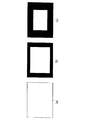
図3は、図1及び図2に示したLCD26での表示例を示した図である。
【0040】
このLCD26での表示は撮影レンズ2のイメージサイズ情報に連動しており、イメージサイズ情報「大」、「中」、「小」それぞれの時、該LCD26には図3(a),(b),(c)に示すように、“L”、“M”、“N”のアイコンが表示されるようにその表示が切り換わる。また、イメージサイズ情報を持たないレンズが装着された時には、図3(d)に示すように、イメージサイズを表す3つのアイコンが全て点滅表示され、撮影者に対してイメージサイズ情報のないレンズが取り付けられている事を警告する。また、警告は表示だけでなく発音体40を同時に鳴らすことでも行う。
【0041】
ここで、上記システムコントローラ3について簡単に説明する。
【0042】
まず、撮影レンズ2がカメラ本体1に装着されて装着検出用ピン50が押し込まれることによってレンズ着脱検知部41にレンズ装着信号が発生すると、システムコントローラ3は装着されている撮影レンズ2のイメージサイズ情報を得るためのコマンドを撮影レンズ2側の不図示のレンズシステムコントローラへ送信し、このコマンドを受けるレンズシステムコントローラは、装着されている該撮影レンズ2のイメージサイズ情報を記憶部49より読み取り、カメラ本体1側のシステムコントローラ3へ送信する。なお、図1では図面簡略化の為、レンズシステムコントローラは不図示であり、カメラ本体1側のシステムコントローラ3のコマンドはI/F部42を介して直接記憶部49に送られる様に図示しているが、実際は上記のような構成になっている。
【0043】
上記イメージサイズ情報を受信するとシステムコントローラ3は、撮影レンズ2のイメージサイズ情報及び画像データから判別したイメージサイズの大きさにより、撮像画面(撮影画面)サイズを識別し、これらの情報に応じた制御信号を上記露出制御、視野枠切換え及び撮像画面サイズを表示する各部へ送出する。また、システムコントローラ3は、装着された撮影レンズ2のイメージサイズがそのままでカメラ本体1側の撮像素子22の撮像範囲に適合するか否かを判定し、不適合と判定された場合、前記撮影レンズ2を通過する光束によって形成される前記撮像素子22上の像の、所定の範囲に対応する像を表わす画像信号に対して所定の信号処理を施すことにより、前記撮影レンズ2のイメージサイズとカメラ本体1側の撮像素子22の撮像範囲を適合させる電子ズーム機能を有している。
【0044】
図4は、視野枠の切換え可能な光学系及び測光光学系の構成を示した図である。
【0045】
視野枠の切換え可能な光学系は、撮影レンズ2(ズームレンズ43、絞り部44、フォーカスレンズ45)を介する光束を撮影素子22側とファインダ側に導くミラー6と、ピント板8と、透過型液晶板9と、ペンタプリズム10と、撮影者に向かう光束の一部を測光センサ13に導くハーフミラーである測光ミラー11と、接眼レンズ15とで構成されていて、上記透過型液晶板9はペンタプリズム10の入射面とピント板8との間に設けられ、図1に示すLCD制御回路27に接続されて表示状態を制御されるようになっており、撮像画面サイズに合わせたサイズの視野枠の大きさの表示切換えが電気的に行えるように構成されている。
【0046】
この透過型液晶板9の、大画面時の視野枠表示と、中画面時の視野枠表示と、小画面時の視野枠表示のそれぞれを示したのが、図5の(a),(b),(c)である。このような視野枠の切換えは、撮像画面サイズが決定された段階において、システムコントローラ3の指示により行われる。
【0047】
撮影レンズ2を透過した被写体からの光束は、観察時には、該撮影レンズ2の後方で光軸o上に45度の角度に斜設されたミラー6により上方に向かって反射され、該ミラー6の上方に配設されたピント板8上に、被写体像が結像される。この被写体像及び前記視野枠はピント板8の上方に配設されたペンタプリズム10と接眼レンズ15を介して撮影者の眼によって視認可能となる。
【0048】
次に、測光光学系の構成について説明する。
【0049】
この実施の形態においては、前記接眼レンズ15の直前に45度に斜設された測光ミラー11により、上記ペンタプリズム10で反射された前記ピント板8からの光束を分割するようになっている。即ち、この測光ミラー11により上記ピント板8の光束は、その一部は接眼レンズ15へ向かって通過直進するが、残りは図4の上方へ向かって反射する。この上方へ向かって反射した光束は、該測光ミラー11の上方に配設されている測光レンズ12を通過して、その上方に配設されている432分割の測光センサ13に入射し、ここで432分割された各範囲の被写体輝度が測光される。また、432分割の測光センサ13は光学的に撮像素子22の結像面と等価の位置に設けられている。
【0050】
上記の測光光学系を含む測光システムは、分割測光手段である432分割の測光センサ13と、該測光センサ13の各エリア毎の検出電流を電圧に変換してシステムコントローラ3に送る測光回路14と、前記読み取ったイメージサイズ情報を基に測光センサ13の非有効部を設定する(前記視野枠の切換えを行う)と共に測光領域として有効とされた部分の測光エリアについて前記測光回路14からの各エリア毎の出力電圧をA/D変換し、測光領域として有効とされた部分について各エリアのグループ化処理を行い、撮影レンズ2のイメージサイズの大きさに応じた係数により各グループ毎の出力電圧の重み付けを変更して、露出値演算を行うシステムコントローラ3とから構成される。
【0051】
上記の様に、この実施の一形態においては、分割測光手段として、432分割の測光センサ13を用いるようにしている。
【0052】
図6は、432分割の測光センサ13の受光面の分割形状を説明する図である。
【0053】
この測光センサ13は、その受光面が格子状に、A1,A2,……,A24、B1,……,R24と432分割されている。この432分割の測光センサ13の全体の範囲は、イメージサイズ大の撮影レンズをカメラ本体1に取り付けた時の撮像範囲に相当している。
【0054】
上記測光センサ13の各エリアA1〜A24、B1〜B24、……、R1〜R24からの検出電流は、図1に示す測光回路14に入力される。すると、測光回路14では、入力された上記432分割の測光センサ13の各エリアA1〜A24、B1〜24、……、R1〜R24の検出電流を検出電圧に変換してシステムコントローラ3に出力する。また、システムコントローラ3は、撮影レンズ2のイメージサイズ情報を基に、前述したように432分割の測光センサ13の非有効領域を設定する。
【0055】
図7は測光センサ13の測光有効領域について示す図であり、432分割の測光センサ13の測光有効領域は、中央部A、該中央部Aの周辺である第1の周辺部部B、該第1の周辺部Bの外側に配置される第2の周辺部Cにグループ化(以下、グループA,B,Cとも記す)される。
【0056】
システムコントローラ3は、上記測光回路14からの各検出電圧をA/D変換してデジタル信号として取り込み、前記グループ化した領域の各デジタル信号に上記の撮影レンズ2のイメージサイズの大きさに応じて重み付けを行い、最適な被写体輝度を演算して露出値を決定することになる。
【0057】
次に、図8〜図11を用いて、432分割の測光センサ13と撮影レンズ2のイメージサイズ大きさの関係と測光エリアのグルーピングについて説明する。
【0058】
図8の中に書かれている円は、イメージサイズ大、中、小それぞれの場合のイメージサークル内の有効撮像範囲を示すものであり、それらの円を432分割測光センサ13上に表したもので、「イメージサイズ(大)」、「イメージサイズ(中)」、「イメージサイズ(小)」の円は、それぞれのイメージサイズの場合の有効撮像範囲(周辺光量落ち等考慮して撮影に堪える範囲)を示したものである。
【0059】
図9は「イメージサイズ(大)」の時に使用される測光エリアについて説明する為の図であり、この時の測光エリアは、「イメージサイズ(大)の時の測光エリア(撮像範囲)」で示す矩形内となり、432分割の測光センサ13全体となる。従って、この時の測光エリアは図15の該当部に示されるグループA、グループB、グループCにグルーピングされる。そして、露出演算時に、システムコントローラ3にて各測光エリア毎に測光値に対し重み付けが行われる。
【0060】
詳しくは、「イメージサイズ(大)」の際、上記測光センサ13の各グループA〜Cに与えられる重み付け係数a,b,cは、a=1、b=1、c=0.8となる。
【0061】
図10は「イメージサイズ(中)」の時に使用される測光エリアについて説明する為の図であり、この時の測光エリアは、「イメージサイズ(中)の時の測光エリア(撮像範囲)」で矩形で示される内側となる。この時の測光エリアは図15の該当部に示されるグループA、グループB、グループCにグルーピングされる。そして、露出演算時にシステムコントローラ3にて各測光エリア毎に測光値に対し重み付けが行われる。
【0062】
詳しくは、「イメージサイズ(中)」の際、上記測光センサ13の各グループに与えられる重み付け係数a,b,cは、a=1、b=1、c=0.8となる。
【0063】
図11は「イメージサイズ(小)」の時に使用される測光エリアについて説明する為の図であり、この時の測光エリアは、「イメージサイズ(小)の時の測光エリア(撮像範囲)」で矩形で示される内側となる。この時の測光エリアは図15の該当部に示されるグループA、グループB、グループCにグルーピングされる。そして、露出演算時にシステムコントローラ3にて各測光エリア毎に測光値に対し重み付けが行われる。
【0064】
詳しくは、「イメージサイズ(小)」の際、上記測光センサ13の各グループに与えられる重み付け係数a,b,cは、a=1、b=1、c=0.8となる。
【0065】
イメージサイズ大中小それぞれでの撮像素子22上の撮像範囲も、上記各測光エリアと等価の範囲となる。
【0066】
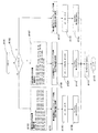
図12は露出情報の設定までの流れを示したフローチャートであり、432分割測光センサ13の非有効領域を設定し、有効領域のグルーピングを行い、上記各イメージサイズに対する測光エリア各グループ毎の重み付けを行って、撮影レンズ2のイメージサイズに最適の被写体輝度が演算されるまでにどのように設定されるかを主に示している。
【0067】
図12において、ステップ#1001よりシーケンスをスタートし、まずステップ#1002にて、各設定フラグ等の情報のイニシャライズを行い、次のステップ#1003にて、撮影レンズ2が装着されたか否かを判定し、装着された事を判定すればステップ#1004へ進み、装着されていない場合はこのステップ#1003を繰り返す。
【0068】
ステップ#1004へ進むと、ストロボモードの設定及び撮影レンズ2のイメージサイズの読み込みを行う。ストロボモードは、信号発生回路10に接続された不図示のストロボモード設定スイッチ(本実施の形態では押しボタンスイッチを想定)の押し込み操作に応じて、「低輝度自動発光」→「強制発光」→「発光停止」から再び「低輝度自動発光」の各モードの順に、ループ状にスクロールして設定される。但し、イニシャライズ時は、低輝度自動発光モードに設定される。また、撮影レンズ2のイメージサイズ情報は、前述したように、該撮影レンズ2内の記憶部49に記憶されているイメージサイズ情報をI/F部42を介して通信によりシステムコントローラ3に読み込まれる。
【0069】
上記ストロボモード、イメージサイズの設定が終了したらステップ#1005へ進み、ここでは上記測光センサ13の432箇所の分割範囲A1〜A24、B1〜24、……、R1〜R24での各エリア毎の測光値VA1〜VA24、VB1〜24、……、VR1〜VR24を読み込む。そして、次のステップ#1006において、測光エリアのグルーピング処理及び重み付けを行うサブルーチンへ飛ぶ。
【0070】
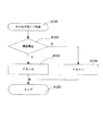
図13は、前記グルーピング及び重み付けサブルーチンを示したものである。
【0071】
このグルーピング及び重み付けサブルーチンは、上記ステップ#1004にて得られた撮影レンズ2のイメージサイズ情報や、上記ステップ#1005にて前記測光センサ13にて得られた各測光値を用いてその処理が進められていく。
【0072】
ステップ#1101でグルーピング及び重み付けサブルーチンをスタートし、まずステップ#1102において、上記イメージサイズ情報が「イメージサイズ(大)」、「イメージサイズ(中)」もしくは「イメージサイズ(小)」の何れであるかの判定を行う。この結果、「イメージサイズ(大)」であればステップ#1111へ進み、「イメージサイズ(中)」であればステップ#1103へ進み、「イメージサイズ(小)」であればステップ#1107へ進む。
【0073】
上記ステップ#1102にて「イメージサイズ(大)」と判定してステップ#1111へ進むと、ここでは「イメージサイズ(大)」の場合であるので、432分割の測光センサ13の全エリアが有効領域となるため、測光範囲外エリアの設定処理は行わないでグルーピング処理を行う。グルーピング処理においては、図9に示されるように、中央部A(グループA)は、G10〜G15、H10〜H15、……、L10〜L15を設定する。中央部Aの周辺の第1の周辺部B(グループB)は、D7〜D18、E7〜E18、……、O7〜O18を設定する。前記第1の周辺部Bの外側に配置される第2の周辺部C(グループC)は、A1〜A24、B1〜B24、……、R1〜R24を設定する。
【0074】
そして、次のステップ#1112にて、各グループA〜Cに対する重み付け係数を、a=1,b=1,c=0.8に設定し、ステップ#1113へ進む。
【0075】
ステップ#1113へ進むと、まず各グループ毎の測光値を演算する。グループAの測光値VAは、グループA内の各エリアの測光値VG10〜VG15、VH10〜VH15、……、VL10〜VL15を積算する事によって得る。グループBの測光値VBは、グループB内の各エリアの測光値VD7〜VD18、VE7〜VE18、……、VO7〜VO18を積算する事によって得る。グループCの測光値VCは、グループC内の各エリアの測光値VA1〜VA24、VB1〜VB24、……、VR1〜VR24を積算する事によって得る。次いで、後述の図12のステップ#1011にて逆光を判定するために用いられる、上記中央部Aの測光値VAに対してその重み付け係数aにより重み付けされた逆光判定用中央測光値Svと、該中央部A以外の測光範囲(上記第1の周辺部Bと第2の周辺部C)の各測光値VB,VCに対してその重み付け係数b,cにより重み付けされた値を基に得られる逆光判定用周辺測光値BCvとを設定する。
【0076】
詳しくは、中央測光値Sv,逆光判定用周辺測光値BCvを、
Sv=VA×a
BCv=VB×b+VC×c
に設定して、ステップ#1114へ進む。
【0077】
また、上記ステップ#1102にて、「イメージサイズ(中)」と判定してステップ#1103へ進んだ場合は、上記ステップ#1004で得られた撮影レンズ2のイメージサイズ情報を基に432分割の測光センサ13の非有効エリアを設定する。また、「イメージサイズ(中)」の場合は、該ステップ#1103の枠内に書かれているエリアが非有効エリアとなる。
【0078】
続くステップ#1104では、有効な測光エリアについてグルーピング処理を行う。グルーピング処理においては、図10に示されるように、中央部Aは、H11〜H14、I11〜I14、J11〜J14、K11〜K14を設定する。中央部Aの周辺である第1の周辺部Bは、F9〜F16、G9〜G16,……、M9〜M16を設定する。前記第1の周辺部Bの外側に配置される第2の周辺部Cは、D5〜D20、E5〜E20、……、O5〜O20を設定する。そして、次のステップ#1105にて、各グループA〜Cに対する重み付け係数を、a=1,b=1,c=0.8に設定し、ステップ#1106へ進む。
【0079】
ステップ#1106へ進むと、まず各グループ毎の測光値を演算する。グループAの測光値VAは、グループA内の各エリアの測光値VH11〜VH14、VI11〜VI14、VJ11〜VJ14、VK11〜VK14を積算する事によって得る。グループBの測光値VBは、グループB内の各エリアの測光値VF9〜VF16、VG9〜VG16,……、VM9〜VM16を積算する事によって得る。グループCの測光値VCは、グループC内の各エリアの測光値VD5〜VD20、VE5〜VE20、……、VO5〜O20を積算する事によって得る。次いで、後述の図12のステップ#1011にて逆光を判定するために用いる、前記と同様の中央測光値Svと逆光判定用周辺測光値BCvとを設定する。
【0080】
詳しくは、中央測光値Sv,逆光判定用周辺測光値BCvを
Sv=VA×a
BCv=VB×b+VC×c
に設定して、ステップ#1114へ進む。
【0081】
また、上記ステップ#1102にて「イメージサイズ(小)」と判定してステップ#1107へ進んだ場合、上記ステップ#1004で得られた撮影レンズ2のイメージサイズ情報を基に、432分割の測光センサ13の非有効エリアを設定する。また、「イメージサイズ(小)」の場合は、ステップ#1107の枠内に書かれているエリアが非有効エリアとなり、A1〜A24、B1〜B24、……、R1〜R24となる。
【0082】
次にステップ#1108にて、有効な測光エリアについてグルーピング処理を行う。グルーピング処理においては、図11に示されるように、中央部AはI12、I13、J12、J13を設定する。前記中央部Aの周辺である第1の周辺部Bは、H11〜H14、I11、I14、J11、J14、K11〜K14を設定する。前記第1の周辺部Bの外側に配置される第2の周辺部Cは、G9〜G16、H9、H10、H15、H16、……、L9〜L16を設定する。そして、次のステップ#1109にて、各グループA〜Cに対する重み付け係数を、a=1,b=1,c=0.8に設定し、ステップ#1110へ進む。
【0083】
ステップ#1110へ進むと、まず各グループ毎の測光値を演算する。グループAの測光値VAは、グループ内Aの各エリアの測光値VI12、VI13、VJ12、VJ13を積算する事によって得る。グループBの測光値VBは、グループB内の各エリアの測光値VH11〜VH14、VI11、VI14、VJ11、VJ14、VK11〜VK14を積算する事によって得る。グループCの測光値VCは、グループC内の各エリアの測光値VG9〜VG16、VH9、VH10、VH15、……、VL9〜VL16を積算する事によって得る。次いで、後述の図12のステップ#1011にて逆光を判定するために用いる、上記と同様の逆光判定用中央測光値Svと、逆光判定用周辺測光値BCvとを設定する。
【0084】
詳しくは、中央測光値Sv,逆光判定用周辺測光値BCvを、
Sv=VA×a
BCv=VB×b+VC×c
に設定して、ステップ#1114へ進む。
【0085】
上記ステップ#1113、#1106もしくはステップ#1110の処理を終え、ステップ#1114へ進むと、撮影レンズ2のイメージサイズ情報に応じて重み付けされた補正被写体輝度Evを設定する。該補正被写体輝度Evは、上記測光センサ13に設定された各グループA,B,Cの測光値VA,VB,VCに重み付け係数a,b,cを掛けて、それぞれの項を加えた演算式
Ev=VA×a+VB×b+VC×c
より求める。そして、次のステップ#1115にて、グルーピング及び重み付けサブルーチンを終了して、図12に示されているフローチャートのステップ#1006に戻る。
【0086】
図12に戻り、ステップ#1006にて重み付けサブルーチンから戻ってきたら、ステップ#1007に進む。そして、再びこのステップ#1007において、ストロボモード判定サブルーチンへ飛ぶ。このストロボモード判定サブルーチンについて、図14のフローチャートにより説明する。
【0087】
図14のステップ#1201にてストロボモード判定サブルーチンをスタートし、まずステップ#1202にて、上記図12のステップ#1004にてストロボの発光停止が設定されたか否かを判定する。この結果、ストロボの発光停止が設定されていなければステップ#1204へ進み、ストロボ発光フラグFSを立てて(FS=1(ストロボ発光許可))、ステップ#1205へ進む。一方、ステップ#1202にてストロボの発光停止が設定されていればステップ#1203へ進み、該ストロボ発光フラグFSを立てずに(FS=0(ストロボ発光禁止))、ステップ#1205へ進む。
【0088】
ステップ#1205へ進むと、このストロボモード判定サブルーチンを終了して、上記図12のステップ#1007に戻る。
【0089】
再び上記図12に戻り、ステップ#1007にてストロボモード判定サブルーチンから戻ってきたらステップ#1008へ進み、ここでは設定されたイメージサイズ情報での重み付けされた補正被写体輝度値Evが所定輝度値E0より低いか否かの低輝度判定を行う。この結果、「Ev<E0」の低輝度の場合はステップ#1009へ進み、ここでストロボ発光が許可されているか否かを判定し、ストロボ発光が許可されていればステップ#1010へ進み、ストロボ発光を設定してステップ#1015へ進み、本シーケンスを終了する。また、上記ステップ#1009にてストロボ発光が許可されていなければ後述するステップ#1014へ進む。
【0090】
上記上記ステップ#1008にて、「Ev<E0」でない、つまり低輝度でないと判定した場合はステップ#1011へ進み、前述のようにして求めた中央測光値Svと逆光判定用周辺測光値BCvと用いて逆光判定を行う。つまり、トリミング範囲の周辺の輝度としての逆光判定用周辺測光値BCvに対して、トリミング範囲の中央付近の輝度としての逆光判定用中央測光値Svが、どの程度小さいかを逆光用所定輝度値Ejを基準として、「BCv−Sv≧Ej」の関係であるか否かによる逆光判定を行う。この結果、中央付近がそれほど暗くなく、「BCv−Sv≧Ej」の関係が成り立たずに逆光でないと判定すれば、ステップ#1014へ進む。一方、中央付近が暗く、「BCv−Sv≧Ej」の関係が成り立ち、逆光と判定すれば、ステップ#1012へ進む。
【0091】
ステップ#1012では、ストロボ発光が許可されているか否かを判定し、ストロボ発光フラグFSが「FS=1」に設定されていて、ストロボ発光が許可されていれば上記ステップ#1010へ進み、上述したようにストロボ発光を設定して、ステップ#1015に進んで、本シーケンスを終了するが、上記ステップ#1012にてストロボ発光フラグFSが「FS=1」に設定されてなくて、ストロボ発光が許可されていなければ、ステップ#1013へ進む。
【0092】
ステップ#1013へ進むと、トリミング範囲全体の重み付けされた補正被写体輝度値Evを逆光補正する。該逆光補正は、該トリミング範囲全体の重み付けされた補正被写体輝度値Evを小さくして、中央付近の重み付けされた中央輝度値Svに近づけることにより、中央付近が暗いという判定に対する中央付近の露出不足を補う。このために、同重み付け補正された輝度値Evから逆光補正所定輝度値Ehを差し引いた輝度値を逆光補正輝度値Evとして新たに設定し直し、つまり、
Ev=Ev−Eh
として、ステップ#1014に進む。
【0093】
最後にステップ#1014において、各条件で設定された輝度値Evにより、シャッタ速度、絞り値を設定して、ステップ#1015へ進み、本シーケンスは終了となる。
【0094】
以上の実施の形態によれば、異なるイメージサイズの交換式の撮影レンズ2をカメラ本体1に装着可能であり、撮影素子22上の被写体像の所定の範囲に対応する像を拡大する電子ズームにより、前記撮影レンズ2のイメージサイズを前記カメラ本体1の撮像範囲に適合させる機能を有する電子カメラにおいて、前記撮像素子22への露光量を測定するために例えば432の測光エリアに分割された分割測光手段である測光センサ13と、該測光センサ13が測光に使用する測光エリアを撮影レンズ2のイメージサイズを表す情報に基づいて選択し、イメージサイズの異なる撮影レンズが装着された場合でも適切な測光エリアで測光し、前記撮像素子22への露光制御を適切な露出量でできるように(図12のステップ#1004〜#1014)構成したので、何れの撮影レンズが装着されたとしても、該撮影レンズ2のイメージサイズの大きさに応じてケラレがなく、かつ適切な露出の画像データを得る事が可能となる。
【0095】
つまり、撮影レンズ2のイメージサイズに1対1に対応しない大きさの測光領域を有する測光センサ13を用いて最適な露出値を算出することが可能となる。
【0096】
なお、上記実施の形態では、432分割の測光センサ13を測光センサとして使用したが、分割数は複数であればよい。また、露出値をシャッタのシーケンスに入る前に決定しているが、リアルタイム積分(ダイレクト測光)で用いてもよい。
【0097】
【発明の効果】
以上説明したように、本発明によれば、異なるイメージサイズの交換レンズを装着可能な電子カメラにおいて、装着される交換レンズのイメージサイズ情報に応じて適切な測光領域を設定することができる電子カメラを提供できるものである。
【図面の簡単な説明】
【図1】本発明の実施の形態に係るデジタルカメラシステムの構成を示すブロック図である。
【図2】図1のデジタルカメラ本体と撮影レンズを示す斜視図である。
【図3】本発明の実施の形態においてファインダ及び測光光学系を説明する為の光学配置図である。
【図4】本発明の実施の形態においてファイダ視野枠の変化について説明する為の図である。
【図5】本発明の実施の形態において撮像サイズ表示について説明する為の図である。
【図6】本発明の実施の形態において測光センサ分割形状について説明する為の図である。
【図7】本発明の実施の形態において測光センサのグルーピング形状について説明する為の図である。
【図8】本発明の実施の形態において測光センサとイメージサイズの関係について説明する為の図である。
【図9】本発明の実施の形態においてイメージサイズ大の場合の測光センサとイメージサイズの関係を示す図である。
【図10】本発明の実施の形態においてイメージサイズ中の場合の測光センサとイメージサイズの関係を示す図である。
【図11】本発明の実施の形態においてイメージサイズ小の場合の測光センサとイメージサイズの関係を示す図である。
【図12】本発明の実施の形態において測光動作を示すフローチャートである。
【図13】本発明の実施の形態において測光領域選択及びグルーピングを説明する為のフローチャートである。
【図14】本発明の実施の形態においてストロボ設定時の動作を示すフローチャートである。
【図15】本発明の実施の形態において測光センサのグルーピングを示す図である。
【符号の説明】
1 カメラ本体
2 撮影レンズ
3 システムコントローラ
4 シャッタ
5 シャッタ制御回路
6 ミラー
7 ミラー制御回路
8 透過型液晶板
9 ピント板
10 ペンタプリズム
11 測光ミラー
12 測光レンズ
13 測光センサ
14 測光回路
15 接眼レンズ
16 姿勢検知センサ
17 測距センサ
18 測距回路
19 測色センサ
20 ホワイトバランス用A/D回路
21 ホワイトバランス制御回路
22 撮像素子
23 撮像回路
24 A/D変換回路
25 メモリ
27 LCD制御回路
26 LCD
28 記録媒体
29 画像処理回路
30 圧縮伸長回路
31 ストロボ
32 外部I/F部
33 信号発生回路
34 スイッチ(SW1)
35 スイッチ(SW2)
36 ズームスイッチ
37 マクロスイッチ
38 イメージサイズ判別スタートスイッチ
39 駆動回路
40 発音体
41 レンズ着脱検知部
42 I/F部
43 ズームレンズ
44 絞り部
45 フォーカスレンズ
46 ズームモータ
47 絞りアクチュエータ
48 AFモータ
51 カメラ側マウント
52 レンズ側マウント[0001]
BACKGROUND OF THE INVENTION
The present invention relates to an electronic camera with interchangeable lenses. thing It is.
[0002]
[Prior art]
Some electronic cameras with interchangeable lenses have different mount diameters for each camera body and interchangeable lens with different image sizes. However, with such cameras, the versatility of interchangeable lenses is poor. . However, if all the mounts are shared, there is no problem for a camera body for a small image size if it is an interchangeable lens with a large image size. However, if the image size of the interchangeable lens is small, vignetting of the light beam (vignetting) Such problems arise.
[0003]
In contrast, for example, as shown in JP-A-2-33267 and JP-A-2-33268, an interchangeable lens having a small image size cannot be mechanically attached to a camera body having a large image size. Occurrence of problems such as vignetting can be prevented. Further, as disclosed in Japanese Patent Laid-Open No. 2-39777, the interchangeable lens and the camera body are electrically connected, and the camera body side is based on information related to the image size of the interchangeable lens stored on the lens side. If it is determined that the image size of the interchangeable lens does not match the image size (when the image size on the interchangeable lens side is small), a configuration may be considered in which a warning is issued.
[0004]
On the other hand, all of the above electronic cameras prevent the occurrence of problems such as vignetting by avoiding the mounting of the interchangeable lens when the image size of the interchangeable lens is not compatible with the camera body. The versatility of the lens is not sufficiently secured.
[0005]
Therefore, for the purpose of providing an electronic camera that can obtain a good shot image without vignetting even when an interchangeable lens having an image size that does not fit the camera body is mounted, the camera body having a camera side mount And an interchangeable lens having a lens-side mount coupled to the camera-side mount, and an input means for inputting information representing an image size of the interchangeable lens to the camera body, and the input means Based on the information, a determination unit that determines whether or not the image size of the interchangeable lens is adapted to the camera body as it is, and an image sensor formed by the interchangeable lens when the determination unit determines that the image size is incompatible The image signal representing the above image is subjected to signal processing by an electronic circuit to thereby obtain the image. The electronic zoom for enlarging an image corresponding to a predetermined range of the image on the element, has also been proposed to adapt the camera to the image size of the interchangeable lens.
[0006]
In addition, as shown in Japanese Utility Model Publication No. 5-66629, a silver halide camera that can switch between a standard screen size and a panoramic screen size provided in the camera, the photometric area of the photometric element is the screen size. Something that has been proposed to meet
[0007]
[Problems to be solved by the invention]
However, the conventional method described above has the following disadvantages.
[0008]
In a camera that changes the imaging size in accordance with the image size of the photographic lens, there is no disclosure that changes the photometric area according to the change of the imaging range.
[0009]
In addition, a camera that can change the shooting range is disclosed in which the photometry area is changed according to the change of the shooting area, but it does not support lenses with different image sizes. There were problems such as shooting and inaccurate exposure.
[0010]
(Object of invention)
An object of the present invention is to provide an electronic camera capable of setting an appropriate photometric area in accordance with image size information of an attached interchangeable lens in an electronic camera capable of attaching an interchangeable lens having a different image size. It is.
[0011]
[Means for Solving the Problems]
To achieve the above objective, The present invention Camera side mount that can be combined with the lens side mount of the interchangeable lens, Divided photometric means for dividing the area into a plurality of areas, and the number of photometric areas used for measuring a photometric value used for controlling the exposure amount among the plurality of photometric areas is the image size information from the interchangeable lens. The photometric area used for the measurement is within the imaging range of the image sensor on the camera body side. This is an electronic camera.
[0013]
DETAILED DESCRIPTION OF THE INVENTION
Hereinafter, the present invention will be described in detail based on illustrated embodiments.
[0014]
FIG. 1 is a block diagram showing an internal configuration of an electronic camera (digital camera system) according to an embodiment of the present invention.
[0015]
As shown in FIG. 1, an electronic camera according to an embodiment of the present invention includes a
[0016]
The
[0017]
[0018]
[0019]
[0020]
[0021]
A
[0022]
1a and 1b are electrically connected to each other when the
[0023]
On the other hand, the photographing
[0024]
43 is a zoom lens that is a variable magnification optical system, and 44 is a stop that is a light amount limiting unit that limits the amount of incident light of a light beam from a subject (hereinafter referred to as a subject light beam) collected by a photographing optical system including the
[0025]
[0026]
As described above, the
[0027]
When the
[0028]
As shown in FIG. 2 to be described later, a photographic lens mounting
[0029]
In this connected state, in addition to various electrical circuits inside the
[0030]
As the
[0031]
The plurality of input switches are for supplying various instruction signals to the
[0032]
As the various switches constituting the input switch, for example, a release SW1 that generates a predetermined instruction signal for executing a photographing preparation operation such as photometry and AF corresponding to a
[0033]
The
[0034]
Then, the
[0035]
FIG. 2 is a perspective view showing an appearance of a single-lens reflex electronic camera having the above-described configuration, and shows a state in which the photographing
[0036]
As shown in FIG. 2, the
[0037]
Further, a photographic lens mounting
[0038]
Furthermore, when the
[0039]
FIG. 3 is a diagram showing a display example on the
[0040]
The display on the
[0041]
Here, the
[0042]
First, when a lens attachment signal is generated in the lens attachment /
[0043]
Upon receiving the image size information, the
[0044]
FIG. 4 is a diagram showing the configuration of an optical system and a photometric optical system in which the field frame can be switched.
[0045]
The optical system in which the field frame can be switched includes a
[0046]
This transmissive
[0047]
At the time of observation, the light beam from the subject that has passed through the
[0048]
Next, the configuration of the photometric optical system will be described.
[0049]
In this embodiment, the light beam from the
[0050]
The photometric system including the photometric optical system described above includes a 432-divided
[0051]
As described above, in this embodiment, the 432-divided
[0052]
FIG. 6 is a diagram for explaining the divided shape of the light receiving surface of the 432-divided
[0053]
The
[0054]
Detected currents from the areas A1 to A24, B1 to B24,..., R1 to R24 of the
[0055]
FIG. 7 is a diagram showing the photometric effective area of the
[0056]
The
[0057]
Next, the relationship between the image size size of the 432-divided
[0058]
The circles written in FIG. 8 indicate the effective imaging range in the image circle when the image size is large, medium, and small, and these circles are represented on the 432
[0059]
FIG. 9 is a diagram for explaining the photometry area used at the time of “image size (large)”. The photometry area at this time is “the photometry area at the time of image size (large) (imaging range)”. The entire
[0060]
Specifically, when “image size (large)” is set, the weighting coefficients a, b, and c given to the groups A to C of the
[0061]
FIG. 10 is a diagram for explaining the photometry area used at the time of “image size (medium)”. The photometry area at this time is “the photometry area (image pickup range) at the time of image size (medium)”. The inside is indicated by a rectangle. The photometry areas at this time are grouped into group A, group B, and group C shown in the corresponding part of FIG. In the exposure calculation, the
[0062]
Specifically, when “image size (medium)” is set, the weighting coefficients a, b, and c given to each group of the
[0063]
FIG. 11 is a diagram for explaining a photometric area used when “image size (small)”. The photometric area at this time is “photometric area (imaging range) when image size (small)”. The inside is indicated by a rectangle. The photometry areas at this time are grouped into group A, group B, and group C shown in the corresponding part of FIG. In the exposure calculation, the
[0064]
For more information, see “Image Size ( small ) ", The weighting coefficients a, b, and c given to the groups of the
[0065]
The imaging range on the
[0066]
FIG. 12 is a flowchart showing the flow up to the setting of exposure information. The non-effective area of the 432-
[0067]
In FIG. 12, the sequence is started from step # 1001, first, at
[0068]
In
[0069]
When the setting of the strobe mode and the image size is completed, the process proceeds to step # 1005. 432 The photometric values VA1 to VA24, VB1 to 24,..., VR1 to VR24 for each area in the divided ranges A1 to A24, B1 to 24,. Then, in the
[0070]
FIG. 13 shows the grouping and weighting subroutine.
[0071]
This grouping and weighting subroutine proceeds with the processing using the image size information of the photographing
[0072]
In
[0073]
If it is determined that “image size (large)” in
[0074]
Then, in the
[0075]
In
[0076]
Specifically, the central photometric value Sv, the peripheral photometric value BCv for backlight determination,
Sv = VA × a
BCv = VB × b + VC × c
And go to
[0077]
If it is determined in
[0078]
In the
[0079]
In
[0080]
Specifically, the central photometric value Sv and the peripheral photometric value BCv for backlight determination
Sv = VA × a
BCv = VB × b + VC × c
And go to
[0081]
If it is determined in
[0082]
Next, in
[0083]
In
[0084]
Specifically, the central photometric value Sv, the peripheral photometric value BCv for backlight determination,
Sv = VA × a
BCv = VB × b + VC × c
And go to
[0085]
Step # above 1113 When step # 1106 or
Ev = VA × a + VB × b + VC × c
Ask more. Then, in the
[0086]
Returning to FIG. 12, when returning from the weighting subroutine in
[0087]
In
[0088]
When the process proceeds to step # 1205, this strobe mode determination subroutine is terminated, and the process returns to step # 1007 in FIG.
[0089]
Returning to FIG. 12 again, when returning from the strobe mode determination subroutine in
[0090]
If it is determined in
[0091]
In
[0092]
In
Ev = Ev−Eh
Then, the process proceeds to step # 1014.
[0093]
Finally, in
[0094]
According to the above embodiment, the interchangeable
[0095]
In other words, it is possible to calculate an optimum exposure value using the
[0096]
In the above embodiment, the 432-divided
[0097]
【The invention's effect】
As described above, according to the present invention, in an electronic camera capable of mounting an interchangeable lens having a different image size, an appropriate photometric area can be set according to the image size information of the mounted interchangeable lens. Can be provided.
[Brief description of the drawings]
FIG. 1 is a block diagram showing a configuration of a digital camera system according to an embodiment of the present invention.
2 is a perspective view showing a digital camera body and a photographing lens in FIG. 1. FIG.
FIG. 3 is an optical layout diagram for explaining a finder and a photometric optical system in the embodiment of the present invention.
FIG. 4 is a diagram for explaining a change in finder field frame in the embodiment of the present invention.
FIG. 5 is a diagram for explaining imaging size display in the embodiment of the present invention;
FIG. 6 is a diagram for explaining a photometric sensor division shape in the embodiment of the present invention.
FIG. 7 is a diagram for explaining grouping shapes of photometric sensors in the embodiment of the present invention.
FIG. 8 is a diagram for explaining a relationship between a photometric sensor and an image size in the embodiment of the present invention.
FIG. 9 is a diagram showing a relationship between a photometric sensor and an image size when the image size is large in the embodiment of the present invention.
FIG. 10 is a diagram showing a relationship between a photometric sensor and an image size when the image size is in the embodiment of the present invention.
FIG. 11 is a diagram showing a relationship between a photometric sensor and an image size when the image size is small in the embodiment of the present invention.
FIG. 12 is a flowchart showing a photometric operation in the embodiment of the present invention.
FIG. 13 is a flowchart for explaining photometric area selection and grouping in the embodiment of the present invention;
FIG. 14 is a flowchart showing an operation when setting a strobe in the embodiment of the present invention;
FIG. 15 is a diagram showing grouping of photometric sensors in the embodiment of the present invention.
[Explanation of symbols]
1 Camera body
2 Photo lens
3 System controller
4 Shutter
5 Shutter control circuit
6 Mirror
7 Mirror control circuit
8 Transmission type liquid crystal plate
9 Focus plate
10 Penta prism
11 Photometric mirror
12 Photometric lens
13 Photometric sensor
14 Photometric circuit
15 Eyepiece
16 Attitude detection sensor
17 Distance sensor
18 Distance measuring circuit
19 Colorimetric sensor
20 A / D circuit for white balance
21 White balance control circuit
22 Image sensor
23 Imaging circuit
24 A / D conversion circuit
25 memory
27 LCD control circuit
26 LCD
28 Recording media
29 Image processing circuit
30 Compression / decompression circuit
31 Strobe
32 External I / F section
33 Signal generation circuit
34 Switch (SW1)
35 switch (SW2)
36 Zoom switch
37 Macro switch
38 Image size discrimination start switch
39 Drive circuit
40 pronunciation body
41 Lens attachment / detachment detector
42 I / F section
43 Zoom lens
44 Aperture
45 Focus lens
46 Zoom motor
47 Aperture actuator
48 AF motor
51 Camera side mount
52 Lens side mount
Claims (1)
領域を複数に分割して測光する分割測光手段とを有し、
前記複数の測光領域のうち露光量の制御に用いる測光値の測定に用いる測光領域の数が前記交換レンズからのイメージサイズ情報に基づいて異なり、当該測定に用いる測光領域はカメラ本体側の撮像素子の撮像範囲内であることを特徴とする電子カメラ。A camera-side mount that can be combined with the lens-side mount of the interchangeable lens;
A divided photometric means for measuring light by dividing an area into a plurality of areas,
Among the plurality of photometric areas, the number of photometric areas used for measuring the photometric value used for controlling the exposure amount differs based on the image size information from the interchangeable lens, and the photometric area used for the measurement is an image sensor on the camera body side. An electronic camera characterized by being within the imaging range .
Priority Applications (1)
| Application Number | Priority Date | Filing Date | Title |
|---|---|---|---|
| JP2001326516A JP4027074B2 (en) | 2001-10-24 | 2001-10-24 | Electronic camera |
Applications Claiming Priority (1)
| Application Number | Priority Date | Filing Date | Title |
|---|---|---|---|
| JP2001326516A JP4027074B2 (en) | 2001-10-24 | 2001-10-24 | Electronic camera |
Publications (3)
| Publication Number | Publication Date |
|---|---|
| JP2003134390A JP2003134390A (en) | 2003-05-09 |
| JP2003134390A5 JP2003134390A5 (en) | 2007-01-25 |
| JP4027074B2 true JP4027074B2 (en) | 2007-12-26 |
Family
ID=19142883
Family Applications (1)
| Application Number | Title | Priority Date | Filing Date |
|---|---|---|---|
| JP2001326516A Expired - Fee Related JP4027074B2 (en) | 2001-10-24 | 2001-10-24 | Electronic camera |
Country Status (1)
| Country | Link |
|---|---|
| JP (1) | JP4027074B2 (en) |
Families Citing this family (4)
| Publication number | Priority date | Publication date | Assignee | Title |
|---|---|---|---|---|
| JP2005006122A (en) * | 2003-06-12 | 2005-01-06 | Olympus Corp | Digital camera system, digital camera body, and interchangeable lens |
| DE602004012747T2 (en) | 2003-06-12 | 2009-04-09 | Olympus Corporation | DIGITAL CAMERA SYSTEM |
| JP4383841B2 (en) | 2003-12-12 | 2009-12-16 | キヤノン株式会社 | interchangeable lens |
| JP2013174637A (en) * | 2012-02-23 | 2013-09-05 | Nikon Corp | Imaging device |
-
2001
- 2001-10-24 JP JP2001326516A patent/JP4027074B2/en not_active Expired - Fee Related
Also Published As
| Publication number | Publication date |
|---|---|
| JP2003134390A (en) | 2003-05-09 |
Similar Documents
| Publication | Publication Date | Title |
|---|---|---|
| JP4576295B2 (en) | Digital camera | |
| US6961089B2 (en) | Digital camera that displays a previously captured image on an LCD when a half-mirror is in motion | |
| EP1972992B1 (en) | Image-capturing device | |
| JP2008199486A (en) | Single lens reflex type electronic imaging device | |
| JP2001042207A (en) | Electronic camera | |
| JP5020800B2 (en) | Imaging apparatus and control method thereof | |
| US20080298797A1 (en) | Imaging apparatus | |
| JP2001169180A (en) | Digital camera | |
| JP2003101860A (en) | Image pickup device, photographing image generation method, program and storage medium | |
| JP4027074B2 (en) | Electronic camera | |
| JP2004104673A (en) | Digital camera | |
| US4998126A (en) | Automatic focus adjustment camera | |
| JPH08220587A (en) | Electronic camera | |
| JP2007017891A (en) | Camera system and imaging apparatus | |
| JP4574075B2 (en) | Foreign matter adhesion determination device and foreign matter adhesion determination method | |
| JP2017021177A (en) | Range-finding point upon lens vignetting, range-finding area transition method | |
| JP2016142853A (en) | Control device of imaging device | |
| JPH09113953A (en) | Apparatus and method for measurement of luminance of camera with variable photometric region | |
| JP2007011070A (en) | Digital single-lens reflex camera | |
| JP4933035B2 (en) | IMAGING DEVICE AND IMAGING DEVICE CONTROL METHOD | |
| JP4079526B2 (en) | camera | |
| JP2003029137A (en) | Automatic focusing detector | |
| JP2003037773A (en) | Imaging method, imaging device, program and storage medium | |
| JPH0560967A (en) | Camera | |
| JP3939899B2 (en) | White balance adjustment device for electronic still camera |
Legal Events
| Date | Code | Title | Description |
|---|---|---|---|
| A521 | Request for written amendment filed |
Free format text: JAPANESE INTERMEDIATE CODE: A523 Effective date: 20041021 |
|
| A621 | Written request for application examination |
Free format text: JAPANESE INTERMEDIATE CODE: A621 Effective date: 20041021 |
|
| A521 | Request for written amendment filed |
Free format text: JAPANESE INTERMEDIATE CODE: A523 Effective date: 20061204 |
|
| A977 | Report on retrieval |
Free format text: JAPANESE INTERMEDIATE CODE: A971007 Effective date: 20070510 |
|
| A131 | Notification of reasons for refusal |
Free format text: JAPANESE INTERMEDIATE CODE: A131 Effective date: 20070522 |
|
| A521 | Request for written amendment filed |
Free format text: JAPANESE INTERMEDIATE CODE: A523 Effective date: 20070720 |
|
| TRDD | Decision of grant or rejection written | ||
| A01 | Written decision to grant a patent or to grant a registration (utility model) |
Free format text: JAPANESE INTERMEDIATE CODE: A01 Effective date: 20071002 |
|
| A61 | First payment of annual fees (during grant procedure) |
Free format text: JAPANESE INTERMEDIATE CODE: A61 Effective date: 20071009 |
|
| FPAY | Renewal fee payment (event date is renewal date of database) |
Free format text: PAYMENT UNTIL: 20101019 Year of fee payment: 3 |
|
| R150 | Certificate of patent or registration of utility model |
Free format text: JAPANESE INTERMEDIATE CODE: R150 |
|
| FPAY | Renewal fee payment (event date is renewal date of database) |
Free format text: PAYMENT UNTIL: 20101019 Year of fee payment: 3 |
|
| FPAY | Renewal fee payment (event date is renewal date of database) |
Free format text: PAYMENT UNTIL: 20111019 Year of fee payment: 4 |
|
| FPAY | Renewal fee payment (event date is renewal date of database) |
Free format text: PAYMENT UNTIL: 20111019 Year of fee payment: 4 |
|
| FPAY | Renewal fee payment (event date is renewal date of database) |
Free format text: PAYMENT UNTIL: 20121019 Year of fee payment: 5 |
|
| FPAY | Renewal fee payment (event date is renewal date of database) |
Free format text: PAYMENT UNTIL: 20131019 Year of fee payment: 6 |
|
| LAPS | Cancellation because of no payment of annual fees |