JP4025097B2 - Exposure equipment - Google Patents
Exposure equipment Download PDFInfo
- Publication number
- JP4025097B2 JP4025097B2 JP2002063290A JP2002063290A JP4025097B2 JP 4025097 B2 JP4025097 B2 JP 4025097B2 JP 2002063290 A JP2002063290 A JP 2002063290A JP 2002063290 A JP2002063290 A JP 2002063290A JP 4025097 B2 JP4025097 B2 JP 4025097B2
- Authority
- JP
- Japan
- Prior art keywords
- light beam
- light
- lens
- recording medium
- light source
- Prior art date
- Legal status (The legal status is an assumption and is not a legal conclusion. Google has not performed a legal analysis and makes no representation as to the accuracy of the status listed.)
- Expired - Fee Related
Links
Images


Classifications
-
- G—PHYSICS
- G02—OPTICS
- G02B—OPTICAL ELEMENTS, SYSTEMS OR APPARATUS
- G02B26/00—Optical devices or arrangements for the control of light using movable or deformable optical elements
- G02B26/08—Optical devices or arrangements for the control of light using movable or deformable optical elements for controlling the direction of light
- G02B26/0875—Optical devices or arrangements for the control of light using movable or deformable optical elements for controlling the direction of light by means of one or more refracting elements
- G02B26/0883—Optical devices or arrangements for the control of light using movable or deformable optical elements for controlling the direction of light by means of one or more refracting elements the refracting element being a prism
-
- G—PHYSICS
- G02—OPTICS
- G02B—OPTICAL ELEMENTS, SYSTEMS OR APPARATUS
- G02B27/00—Optical systems or apparatus not provided for by any of the groups G02B1/00 - G02B26/00, G02B30/00
- G02B27/28—Optical systems or apparatus not provided for by any of the groups G02B1/00 - G02B26/00, G02B30/00 for polarising
- G02B27/283—Optical systems or apparatus not provided for by any of the groups G02B1/00 - G02B26/00, G02B30/00 for polarising used for beam splitting or combining
-
- G—PHYSICS
- G02—OPTICS
- G02B—OPTICAL ELEMENTS, SYSTEMS OR APPARATUS
- G02B27/00—Optical systems or apparatus not provided for by any of the groups G02B1/00 - G02B26/00, G02B30/00
- G02B27/28—Optical systems or apparatus not provided for by any of the groups G02B1/00 - G02B26/00, G02B30/00 for polarising
- G02B27/286—Optical systems or apparatus not provided for by any of the groups G02B1/00 - G02B26/00, G02B30/00 for polarising for controlling or changing the state of polarisation, e.g. transforming one polarisation state into another
Landscapes
- Physics & Mathematics (AREA)
- General Physics & Mathematics (AREA)
- Optics & Photonics (AREA)
- Laser Beam Printer (AREA)
- Mechanical Optical Scanning Systems (AREA)
- Facsimile Heads (AREA)
- Facsimile Scanning Arrangements (AREA)
Description
【0001】
【発明の属する技術分野】
本発明は、露光装置に係り、特に、走査露光によって記録媒体上に画像を形成する露光装置に関する。
【0002】
【従来の技術】
従来より、外周面に感光材料(記録媒体)が装着されたドラムを主走査方向に回転させると共に、上記感光材料に記録すべき画像の画像データに応じて変調されたレーザビームを上記主走査方向と直交する副走査方向に走査させることで、2次元画像を上記感光材料に記録するようにした露光記録装置が用いられている。
【0003】
この種の露光記録装置において、解像度を低くして画像を記録するためには、感光材料表面におけるレーザビームのスポット径を拡大すると共に、副走査方向に対する記録ピッチを大きくするか、又はスポット径の大きさ及び記録ピッチは変更せずに、同一の画像データからなる画素を解像度を低くした分だけ繰り返し記録する方法が採られていた。一方、解像度を高くして画像を記録する場合は、これと逆の方法が採られていた。
【0004】
しかしながら、このようにしてレーザビームのスポット径を拡大、ないし縮小するためには、駆動機構を用いて光学系のレンズ等を駆動する必要があることから、装置が大型化すると共に、コストが上昇する、という問題点があった。また、同一の画像データからなる画素を解像度を低くした分だけ繰り返し記録することで解像度を低くする場合には、副走査方向に対する記録ピッチが一定であるため、記録速度を向上できない、という問題点があった。
【0005】
そこで、これらの問題点を解消するために、本発明の出願人による特開2000−284206号公報に記載の技術では、光源から射出された光を複数に分割し、集光光学系による記録媒体上での集光点を、当該記録媒体の副走査方向に対して複数生成する複数集光点生成手段と、解像度に応じて副走査方向の記録間隔を制御する副走査制御手段と、を備えておき、光源から射出された光を集光光学系を介して記録媒体上に集光させて画像を記録する際に、記録画像の解像度に応じて、複数集光点生成手段により副走査方向に分割して生成される集光点の数を制御することでビームスポットの大きさを調整すると共に、副走査方向のビームスポットの記録間隔を調整することにより、解像度に応じた画像を効率的に記録することを可能としていた。
【0006】
なお、この技術では、上記複数集光点生成手段として、一軸性結晶により構成された偏光光学素子、又は偏角プリズムを適用していた。
【0007】
しかしながら、上記特開2000−284206号公報に記載の技術において複数集光点生成手段として一軸性結晶により構成された偏光光学素子を適用した場合には、一軸性結晶は高価であるため高コストとなってしまう、という問題点があった。
【0008】
また、同公報に記載の技術において複数集光点生成手段として偏角プリズムを適用した場合には、記録画像の画質が悪くなる場合がある、という問題点があった。
【0009】
すなわち、同公報に記載の技術において複数集光点生成手段として偏角プリズムを適用した場合には、偏角プリズムで分割され集光レンズで集光されたレーザビームの焦点位置から光軸方向(深度方向)前後にずれた位置におけるレーザビームのボケ方が光軸方向に対して非対称となる。
【0010】
これは、偏角プリズムにより分割した光を各々焦点位置の分割方向における異なる位置に集光レンズによって集光しているため、焦点位置から光の入射側を見たときには分割された光が互いに離れていく状態となり、焦点位置から光の出射側を見たときには分割された光が接近して交差した後に離れていく状態となって生じる現象であり、この現象によって深度方向に対する記録媒体の配置位置の許容範囲が少なくなり、当該配置位置の深度方向へのずれが僅かであっても、記録媒体への記録画像の画質が悪化する場合があるのである。
【0011】
そこで、これらの問題点を解消するために、本発明の出願人による特願2001−310537号に記載の技術では、走査露光によって記録媒体上に画像を形成する露光装置であって、少なくとも副走査方向についてはブロードエリアで発光する光ビームを射出する光源と、当該光源から射出された光ビームを上記記録媒体上に集光する集光光学系と、有する露光装置に、1本の光ビームを2つに分割する単位表面形状を有する屈折部材が対単位でアレイ状に並ぶように構成したアレイ屈折素子を、上記光ビームの分割方向が上記光源から射出された光ビームのブロードエリア方向と略平行となるように配置していた。
【0012】
これにより、アレイ屈折素子のアレイ対により2つに分割された光ビームは、各々アレイ対の数分の光で構成される。従って、アレイ対の数の集光ビームで1つの集光スポットを構成するので、分割された光ビームを集光レンズによって焦点位置で2つずつ集光スポットをずらして重ね合わせた場合、焦点位置から光ビームの入射側を見たときと、焦点位置から光ビームの出射側を見たときとで、各光ビームのボケ方が光軸方向に対して対称となり、この結果として記録画像の画質を向上することができる。
【0013】
また、このアレイ屈折素子は、光ビームを2つに分割することができるものであれば如何なる材質の材料でも構成することができるので、光ビームを偏光方向に応じて分離する場合に必要となる一軸性結晶を必ずしも用いる必要がなく、低コストに構成することができる。
【0014】
ところで、記録速度の向上を目的として、複数の光源から射出された各レーザビームを各々光ファイバーで単一の露光ヘッドに案内すると共に、当該露光ヘッドにおいて各光ファイバーにおけるレーザビームの出射口端部を副走査方向に並べて配置しておき、上記複数の光源から射出された複数のレーザビームによる露光を同時に行う露光記録装置がある。
【0015】
この種の露光記録装置に対して、前述の特開2000−284206号公報に記載の技術を適用した場合、1つのレーザビームを複数に分割して露光することができるため、記録速度の更なる向上が可能となる。
【0016】
しかしながら、このような光ファイバーを用いた露光記録装置では、光ファイバーに加えられる外力変位(振動変位、圧力変位、ねじれ変位、温度変位等)によって光ファイバーから出射されるレーザビームの偏光方向が時々刻々と変化する場合があり、この場合には複数に分割されたレーザビームの光量が競合してしまい、集光スポットが不安定な形状となってしまうため、記録画像の画質が劣化する、という問題点があった。
【0017】
そこで、この問題点を解消するために、本発明の出願人による特願2001−201407号に記載の技術では、光を射出する光源と、当該光源から射出された光を記録媒体上に集光する集光光学系と、上記光を偏光方向が互いに直交する2つの光に分離する偏光分離素子と、を備えた露光装置に、上記光源と上記偏光分離素子との間に、当該偏光分離素子により分離される光ビームの偏光方向に対して結晶光軸が45度を含む所定範囲の角度で傾斜するように複数の1/2波長板を上記光ビームの全入射領域において各々所定間隔毎に配置して構成した偏光方向制御素子を配置していた。
【0018】
なお、上記結晶光軸は「光学軸」とも呼ばれているものであるが、本明細書では、「結晶光軸」と統一して記載する。更に、上記45度を含む所定範囲の角度は、理想的には45度であるが、当該偏光方向制御素子の製造上許容される範囲内の角度、当該偏光方向制御素子が適用される装置において許容される範囲内の角度等の各種許容範囲内の角度を意味するものである。
【0019】
ここで、図28を参照して、本技術の原理について簡単に説明する。なお、ここでは、本技術の偏光方向制御素子を、1/2波長板と、透過する光の偏光方向に大きな影響を与えない透明平行板と、を組み合わせて構成した場合について説明する。同図に示すように、偏光分離素子により分離する光の偏光方向を(x,y)としたとき、偏光方向制御素子における1/2波長板の結晶光軸の方向が(x,y)に対して45度傾斜される方向となるように偏光方向制御素子を配置するものとする。なお、このときの1/2波長板における結晶光軸の座標系を(X,Y)とする。また、ここでは、偏光方向制御素子における透明平行板と1/2波長板の光透過率の差がないか、無視できるほど小さいことを前提として、1/2波長板に入射する光の光量と、入射しない光の光量との比が1:1となるように光量分配される位置に偏光方向制御素子を配置するものとする。
【0020】
偏光方向制御素子に入射される光の電界ベクトルαをα=(a,b)として、1/2波長板に入射する光を考えた場合、(x,y)座標系を45度回転させるための行列をA、Y座標の光を1/2波長位相を遅らせる行列をB、−45度回転させて元の(x,y)座標系に戻す行列をCとすると、それぞれは次のように表わされる。
【0021】
【数1】

従って、1/2波長板を通過した後の光の電界ベクトルβは次のように表わされる。
【0023】
【数2】
αとβは、光量分配として1:1に配分されるように設定されていることから、それぞれの光量Iα、Iβは次のように表わされる。
【0025】
【数3】
従って、それぞれの光を足し合わせたときの光量Iは次のようになる。
【0027】
【数4】
この結果は、1/2波長板を通過した光と、通過しなかった光とを足し合わせた場合、偏光分離素子でxとyの各偏光方向に分離された光は、等光量で分離されることを示している。
【0029】
なお、ここで偏光方向制御素子に設けた透明平行板は必ずしも必要なものではなく、入射された光の偏光方向に大きな影響を与えない他の部材(例えば、ND(Neutral Density)フィルタ)を透明平行板に代えて適用することもでき、これらの部材を設けずに、何もない素通しの状態とすることもできる。
【0030】
以上の原理に基づき、特願2001−201407号に記載の技術における偏光方向制御素子は、光を偏光方向が互いに直交する2つの光に分離する偏光分離素子の上記光の光軸方向上流側に設けられる偏光方向制御素子であって、上記偏光分離素子の光軸方向上流側に設けられた際に、上記光の一部が透過されると共に、上記偏光分離素子により分離される光の偏光方向に対して結晶光軸が45度を含む所定範囲の角度で傾斜するように1/2波長板を配置して構成しているので、偏光分離素子と組み合わせて用いた場合に当該偏光分離素子により光を等光量で分離することが可能となり、偏光分離素子を用いた露光記録装置における記録画像の画質を向上することができる。
【0031】
【発明が解決しようとする課題】
しかしながら、上記特願2001−310537号の技術では、アレイ屈折素子における光ビームの分割部分において回折光が発生するため、この影響によって光ビームの記録媒体上における集光スポットの形状が悪くなり、この結果として記録媒体上に形成される画像の品質が悪化する、という問題点があった。
【0032】
また、上記特願2001−201407号の技術でも、偏光方向制御素子を構成する1/2波長板のエッジ部において回折光が発生するため、この影響によって光ビームの記録媒体上における集光スポットの形状が悪くなり、この結果として記録媒体上に形成される画像の品質が悪化する、という問題点があった。
【0033】
ここで、上記回折光の発生メカニズムについて説明する。なお、ここでは、光ビームを分割するための屈折部材対を複数周期的に並べた場合の回折光について説明する。
【0034】
この場合、複数対の屈折部材で光ビームは2方向に屈折されるので、このうちの一方向に出射される光ビームだけを考えると、屈折部材を透過する光ビームは図29に示すような周期的な開口格子を通過した場合と同様の特性を示す。
【0035】
従って、この周期開口格子を光が通過したときの回折式を解けばよいことになる。一様な光が周期開口格子に入射した場合の回折光の強度分布I(p)は次の(1)式で示される。また、n次回折光の回折角度pn(rad)は次の(2)式で示される。
【0036】
【数5】
【数6】
ただし、Nは周期開口格子(屈折部材)の数、kは光の波数、dは周期開口格子(屈折部材)の幅(mm)、sは開口幅(mm)、pは回折角度(rad)、nは回折光の次数、λは入射光の波長(mm)である。
【0039】
ここで、一例として、次の条件について解いた場合のグラフを図30に示す。なお、同図における横軸は回折角度pで、縦軸は光強度I(p)である。
【0040】
(条件)
周期開口格子の幅d=3(mm)、開口幅s=1.5(mm)、光の波長λ=0.83(μm)
また、このときの一次回折光の回折角度p1は次のようになる。
【0041】
p1=2.8×10⁻⁴(rad)
図30に示されるように、この場合の一次回折光の光強度Iは0次光に対して約40%もの大きさとなっており、他の次数の回折光に比較して集光スポットへの影響が著しく大きいことがわかる。従って、集光スポットと一次回折光との間のずれ量が大きい場合には、記録媒体上に形成される画像の品質が著しく悪化することになる。
【0042】
本発明は上記問題点を解消するためになされたものであり、記録媒体上に形成される画像の品質を向上することができる露光装置を提供することを目的とする。
【0043】
【課題を解決するための手段】
上記目的を達成するために、請求項1記載の露光装置は、走査露光によって記録媒体上に画像を形成する露光装置であり、少なくとも副走査方向についてはブロードエリアで発光する光ビームを射出する光源と、前記光源と前記記録媒体との間に配置されると共に前記光源から射出された光ビームを略平行光束とする第1レンズ、及び該第1レンズと前記記録媒体との間に配置されると共に前記光ビームを前記記録媒体上に集光する第2レンズを含んで構成された集光光学系と、1本の光ビームを2つに分割する単位表面形状を有する屈折部材が対単位でアレイ状に並ぶように構成すると共に、前記光ビームの分割方向が前記光源から射出された光ビームのブロードエリア方向と略平行となるように前記第1レンズと前記第2レンズとの間に配置されたアレイ屈折素子と、を備えた露光装置であって、前記第2レンズの焦点距離fと前記光ビームの波長λとの乗算値f×λを前記屈折部材における前記光ビームの分割領域の分割方向に対する幅dで除算して得られる値(f×λ)/dが後述する所定値以下となるように前記焦点距離f、前記波長λ、及び前記幅dを決定したことを特徴とする。
【0044】
ここで、図面を参照して、本発明の原理について説明する。図25には、ブロードな発光面を有する光源から射出された光ビームを前述の周期開口格子(図29も参照)を通した後に焦点距離がfとされた集光レンズで再結像した場合の概略図が示されている。この場合、同図に示すように、光ビームの集光スポットと一次回折光の各々の中心位置のずれ量はp1×fで表される。
【0045】
一次回折光の回折角度p1は上記(2)式から次の(3)式で表される。
【0046】
【数7】
従って、集光スポットと一次回折光の各々の中心位置のずれ量は次の(4)式で表される。
【0048】
【数8】
このずれ量が大きい場合には、一例として図26(A)に示されるように一次回折光の視認性が大きいため、記録媒体上に形成される画像の品質が著しく劣化することになり、逆に当該ずれ量が小さい場合には、一例として図26(B)に示されるように一次回折光の視認性が小さいため、上記ずれ量が大きい場合に比較して記録媒体上に形成される画像の品質を向上することができる。
【0050】
従って、集光スポットと一次回折光とのずれ量を小さくすることが画質の面では好ましいが、このためには(4)式の右辺で表される値が小さくなるように、焦点距離f、波長λ、及び周期開口格子の幅dを決定すればよい。なお、ここでいう周期開口格子の幅dは、本発明の屈折部材における光ビームの分割領域の分割方向に対する幅dに相当するものである。
【0051】
以上のような原理に基づき、請求項1に記載の露光装置によれば、少なくとも副走査方向についてはブロードエリアで発光する光ビームを射出する光源から射出された光ビームが、集光光学系により、第1レンズによって略平行光束とされた後、第2レンズによって記録媒体上に集光される際に、1本の光ビームを2つに分割する単位表面形状を有する屈折部材が対単位でアレイ状に並ぶように構成されると共に光ビームの分割方向が光源から射出された光ビームのブロードエリア方向と略平行となるように上記第1レンズと上記第2レンズとの間に配置されたアレイ屈折素子によって当該光ビームのブロードエリア方向、すなわち副走査方向に分割される。なお、上記光源には、各種半導体レーザが含まれる。また、上記第1レンズには、各種コリメータレンズが、上記第2レンズには各種集光レンズが、各々含まれる。
【0052】
ここで、請求項1に記載の発明では、上記第2レンズの焦点距離fと上記光ビームの波長λとの乗算値f×λを、アレイ屈折素子を構成する屈折部材における光ビームの分割領域の分割方向に対する幅dで除算して得られる値(f×λ)/dが後述する所定値以下となるように焦点距離f、波長λ、及び幅dが決定される。
【0053】
このように、請求項1に記載の露光装置によれば、少なくとも副走査方向についてはブロードエリアで発光する光ビームを射出する光源と、当該光源と記録媒体との間に配置されると共に当該光源から射出された光ビームを略平行光束とする第1レンズ、及び該第1レンズと記録媒体との間に配置されると共に上記光ビームを記録媒体上に集光する第2レンズを含んで構成された集光光学系と、1本の光ビームを2つに分割する単位表面形状を有する屈折部材が対単位でアレイ状に並ぶように構成すると共に、光ビームの分割方向が光源から射出された光ビームのブロードエリア方向と略平行となるように第1レンズと第2レンズとの間に配置されたアレイ屈折素子と、を備えると共に、上記第2レンズの焦点距離fと上記光ビームの波長λとの乗算値f×λを上記屈折部材における光ビームの分割領域の分割方向に対する幅dで除算して得られる値(f×λ)/dが後述する所定値以下となるように焦点距離f、波長λ、及び幅dを決定しているので、上記光ビームの集光スポットと一次回折光との間のずれ量を小さくすることができ、この結果として記録媒体上に形成される画像の品質を向上することができる。
【0054】
一方、上記目的を達成するために、請求項2記載の露光装置は、走査露光によって記録媒体上に画像を形成する露光装置であり、少なくとも副走査方向についてはブロードエリアで発光する光ビームを射出する光源と、前記光源と前記記録媒体との間に配置されると共に前記光源から射出された光ビームを略平行光束とする第1レンズ、及び該第1レンズと前記記録媒体との間に配置されると共に前記光ビームを前記記録媒体上に集光する第2レンズを含んで構成された集光光学系と、1本の光ビームを2つに分割する単位表面形状を有する屈折部材が対単位でアレイ状に並ぶように構成すると共に、前記光ビームの分割方向が前記光源から射出された光ビームのブロードエリア方向と略平行となるように前記第2レンズと前記記録媒体との間に配置されたアレイ屈折素子と、を備えた露光装置であって、前記アレイ屈折素子と前記記録媒体との間の距離Rと前記光ビームの波長λとの乗算値R×λを前記屈折部材における前記光ビームの分割領域の分割方向に対する幅dで除算して得られる値(R×λ)/dが後述する所定値以下となるように前記距離R、前記波長λ、及び前記幅dを決定したことを特徴とする。
【0055】
すなわち、請求項2に記載の露光装置は、請求項1記載の露光装置と略同様の構成とされており、アレイ屈折素子が第2レンズと記録媒体との間に配置されている点のみが請求項1に記載の発明と異なっている。
【0056】
この場合、一次回折光の回折角度p1は(3)式と同様であるが、集光スポットと一次回折光の各々の中心位置のずれ量は次の(5)式で表される。
【0057】
【数9】
従って、集光スポットと一次回折光とのずれ量を小さくするためには、(5)式の右辺で表される値が小さくなるように、距離R、波長λ、及び幅dを決定すればよいことになり、請求項2に記載の露光装置では、距離Rと波長λとの乗算値R×λを幅dで除算して得られる値(R×λ)/dが後述する所定値以下となるように距離R、波長λ、及び幅dが決定される。
【0059】
なお、本発明の光源には各種半導体レーザが、本発明の第1レンズには各種コリメータレンズが、本発明の第2レンズには各種集光レンズが、各々含まれる。
【0060】
このように、請求項2に記載の露光装置によれば、少なくとも副走査方向についてはブロードエリアで発光する光ビームを射出する光源と、当該光源と記録媒体との間に配置されると共に当該光源から射出された光ビームを略平行光束とする第1レンズ、及び該第1レンズと記録媒体との間に配置されると共に上記光ビームを記録媒体上に集光する第2レンズを含んで構成された集光光学系と、1本の光ビームを2つに分割する単位表面形状を有する屈折部材が対単位でアレイ状に並ぶように構成すると共に、光ビームの分割方向が光源から射出された光ビームのブロードエリア方向と略平行となるように第2レンズと記録媒体との間に配置されたアレイ屈折素子と、を備えると共に、アレイ屈折素子と記録媒体との間の距離Rと上記光ビームの波長λとの乗算値R×λを上記屈折部材における光ビームの分割領域の分割方向に対する幅dで除算して得られる値(R×λ)/dが後述する所定値以下となるように距離R、波長λ、及び幅dを決定しているので、上記光ビームの集光スポットと一次回折光との間のずれ量を小さくすることができ、この結果として記録媒体上に形成される画像の品質を向上することができる。
【0061】
ところで、本発明の発明者による実験により、集光スポットと一次回折光のずれ量が、一例として図27に示される集光スポットの半値半幅を超えると一次回折光の集光スポットに対する影響が大きくなり、画質的にも問題となることが見出された。
【0062】
そこで、請求項1又は請求項2記載の発明における上記所定値は、前記光ビームの前記記録媒体上での集光スポットの半値半幅としている。
【0063】
これによって、一次回折光の影響による画質の劣化を確実に防止することができる。
【0064】
なお、集光スポットと一次回折光のずれの画質に対する影響は、記録媒体上に形成される画像の解像度等によってもある程度左右されるし、要求される画質も一定とは限らないので、上記所定値は上記半値半幅とすることに限らず、当該半値半幅の近傍の値(例えば、当該半値半幅の±10%の値)とすることもできる。
【0065】
一方、上記目的を達成するために、請求項3記載の露光装置は、走査露光によって記録媒体上に画像を形成する露光装置であり、少なくとも副走査方向についてはブロードエリアで発光する光ビームを射出する光源と、前記光源と前記記録媒体との間に配置されると共に前記光源から射出された光ビームを略平行光束とする第1レンズ、及び該第1レンズと前記記録媒体との間に配置されると共に前記光ビームを前記記録媒体上に集光する第2レンズを含んで構成された集光光学系と、1本の光ビームを2つに分割する単位表面形状を有する屈折部材が対単位でアレイ状に並ぶように構成すると共に、前記光ビームの分割方向が前記光源から射出された光ビームのブロードエリア方向と略平行となるように前記光源と前記第1レンズとの間に配置されたアレイ屈折素子と、を備えた露光装置であって、前記光源と前記アレイ屈折素子との間の距離Sと前記光ビームの波長λとの乗算値S×λを前記屈折部材における前記光ビームの分割領域の分割方向に対する幅dで除算して得られる値(S×λ)/dが後述する所定値以下となるように前記距離S、前記波長λ、及び前記幅dを決定したことを特徴とする。
【0066】
すなわち、請求項3に記載の露光装置は、請求項1記載の露光装置と略同様の構成とされており、アレイ屈折素子が光源と第1レンズとの間に配置されている点のみが請求項1に記載の発明と異なっている。
【0067】
この場合、一次回折光の回折角度p1は(3)式と同様であるが、集光スポットと一次回折光の各々の中心位置のずれ量は次の(6)式で表される。
【0068】
【数10】
従って、集光スポットと一次回折光とのずれ量を小さくするためには、(6)式の右辺で表される値が小さくなるように、距離S、波長λ、及び幅dを決定すればよいことになり、請求項3に記載の露光装置では、距離Sと波長λとの乗算値S×λを幅dで除算して得られる値(S×λ)/dが後述する所定値以下となるように距離S、波長λ、及び幅dが決定される。
【0070】
なお、本発明の光源には各種半導体レーザが、本発明の第1レンズには各種コリメータレンズが、本発明の第2レンズには各種集光レンズが、各々含まれる。
【0071】
このように、請求項3に記載の露光装置によれば、少なくとも副走査方向についてはブロードエリアで発光する光ビームを射出する光源と、当該光源と記録媒体との間に配置されると共に当該光源から射出された光ビームを略平行光束とする第1レンズ、及び該第1レンズと記録媒体との間に配置されると共に上記光ビームを記録媒体上に集光する第2レンズを含んで構成された集光光学系と、1本の光ビームを2つに分割する単位表面形状を有する屈折部材が対単位でアレイ状に並ぶように構成すると共に、光ビームの分割方向が光源から射出された光ビームのブロードエリア方向と略平行となるように光源と第1レンズとの間に配置されたアレイ屈折素子と、を備えると共に、光源とアレイ屈折素子との間の距離Sと上記光ビームの波長λとの乗算値S×λを上記屈折部材における光ビームの分割領域の分割方向に対する幅dで除算して得られる値(S×λ)/dが後述する所定値以下となるように距離S、波長λ、及び幅dを決定しているので、上記光ビームの集光スポットと一次回折光との間のずれ量を小さくすることができ、この結果として記録媒体上に形成される画像の品質を向上することができる。
【0072】
ところで、本発明の発明者による実験により、集光スポットと一次回折光のずれ量が、光ビームの出射位置での半値半幅を超えると一次回折光の集光スポットに対する影響が大きくなり、画質的にも問題となることが見出された。
【0073】
そこで、請求項3記載の発明における上記所定値は、前記光ビームの出射位置での半値半幅としている。
【0074】
これによって、一次回折光の影響による画質の劣化を確実に防止することができる。
【0075】
なお、集光スポットと一次回折光のずれの画質に対する影響は、記録媒体上に形成される画像の解像度等によってもある程度左右されるし、要求される画質も一定とは限らないので、上記所定値は上記半値半幅とすることに限らず、当該半値半幅の近傍の値(例えば、当該半値半幅の±10%の値)とすることもできる。
【0076】
なお、請求項1乃至請求項3の何れか1項記載の露光装置は、走査露光によって前記記録媒体上に形成される画像の解像度を示す解像度情報を入力する入力手段と、前記解像度情報によって示される解像度が予め定められた第1解像度である場合に前記アレイ屈折素子が前記光源から射出された光ビームの光軸上から退避され、前記解像度情報によって示される解像度が前記第1解像度より低い第2解像度である場合に前記アレイ屈折素子が前記光軸上に位置されるように当該アレイ屈折素子を移動させる移動手段と、を更に備えることが好ましい。
【0077】
これにより、走査露光によって記録媒体上に形成される画像の解像度を示す解像度情報が入力手段によって入力され、当該解像度情報によって示される解像度が予め定められた第1解像度である場合に本発明のアレイ屈折素子が光源から射出された光ビームの光軸上から退避され、解像度情報によって示される解像度が第1解像度より低い第2解像度である場合にアレイ屈折素子が上記光軸上に位置されるように当該アレイ屈折素子が移動手段によって移動される。
【0078】
従って、このように、走査露光によって記録媒体上に形成される画像の解像度を示す解像度情報を入力し、当該解像度情報によって示される解像度が予め定められた第1解像度である場合にアレイ屈折素子が光源から射出された光ビームの光軸上から退避され、当該解像度情報によって示される解像度が第1解像度より低い第2解像度である場合にアレイ屈折素子が上記光軸上に位置されるように当該アレイ屈折素子を移動しているので、解像度情報を入力するのみによって、記録媒体に画像を記録する際の解像度を容易に変更することができる。
【0079】
更に、請求項1乃至請求項3の何れか1項記載の露光装置は、前記光源を前記光ビームの分割方向に沿って複数配置し、各光源から射出された光ビームを各々アレイ屈折素子によって分割して記録媒体に導くように構成すれば、記録画像の画質を向上できるばかりでなく、画像を高速に記録することができる。
【0080】
一方、上記目的を達成するために、請求項4記載の露光装置は、走査露光によって記録媒体上に画像を形成する露光装置であり、少なくとも副走査方向についてはブロードエリアで発光する光ビームを射出する光源と、前記光源と前記記録媒体との間に配置されると共に前記光源から射出された光ビームを略平行光束とする第1レンズ、及び該第1レンズと前記記録媒体との間に配置されると共に前記光ビームを前記記録媒体上に集光する第2レンズを含んで構成された集光光学系と、前記第1レンズと前記第2レンズとの間に配置されると共に前記光ビームを偏光方向が互いに直交する2つの光に分離する偏光分離素子と、前記偏光分離素子により分離される光ビームの偏光方向に対して結晶光軸が45度を含む所定範囲の角度で傾斜するように複数の1/2波長板を前記光ビームの全入射領域において各々所定間隔cを1周期として配置して構成すると共に前記第1レンズと前記偏光分離素子との間に配置された偏光方向制御素子と、を備えた露光装置であって、前記第2レンズの焦点距離fと前記光ビームの波長λとの乗算値f×λを前記所定間隔cで除算して得られる値(f×λ)/cが後述する所定値以下となるように前記焦点距離f、前記波長λ、及び前記所定間隔cを決定したことを特徴とする。
【0081】
請求項4に記載の露光装置によれば、少なくとも副走査方向についてはブロードエリアで発光する光ビームを射出する光源から射出された光ビームが、集光光学系により、第1レンズによって略平行光束とされた後、第2レンズによって記録媒体上に集光される際に、偏光分離素子によって偏光方向が互いに直交する2つの光に分離される。なお、本発明の光源には各種半導体レーザが、本発明の第1レンズには各種コリメータレンズが、本発明の第2レンズには各種集光レンズが、各々含まれる。また、上記偏光分離素子には、ローションプリズム(Rochon Prism)、ウォラストンプリズム(Wollaston Prism)等の各種プリズムが含まれる。
【0082】
ここで、請求項4に記載の発明では、上記偏光分離素子により分離される光ビームの偏光方向に対して結晶光軸が45度を含む所定範囲の角度で傾斜するように複数の1/2波長板を、上記光ビームの全入射領域において各々所定間隔cを1周期として配置して構成した偏光方向制御素子が、上記第1レンズと上記偏光分離素子との間に配置される。
【0083】
このように構成することにより、請求項4に記載の露光装置では、偏光分離素子により光を等光量で分離することが可能となり、分離された光により記録媒体に画像を記録する際の当該画像の品質を向上することができる。
【0084】
このように構成された露光装置の場合、図29に示される周期開口格子の幅dが本発明の所定間隔cに相当するため、偏光方向制御素子において発生する一次回折光の回折角度p1は上記(2)式から次の(7)式で表される。
【0085】
【数11】
従って、集光スポットと一次回折光の各々の中心位置のずれ量は次の(8)式で表される。
【0087】
【数12】
従って、集光スポットと一次回折光とのずれ量を小さくするためには、(8)式の右辺で表される値が小さくなるように、焦点距離f、波長λ、及び所定間隔cを決定すればよいことになり、請求項4に記載の露光装置では、焦点距離fと波長λとの乗算値f×λを所定間隔cで除算して得られる値(f×λ)/cが後述する所定値以下となるように焦点距離f、波長λ、及び所定間隔cが決定される。
【0089】
このように、請求項4に記載の露光装置によれば、少なくとも副走査方向についてはブロードエリアで発光する光ビームを射出する光源と、当該光源と記録媒体との間に配置されると共に当該光源から射出された光ビームを略平行光束とする第1レンズ、及び該第1レンズと記録媒体との間に配置されると共に上記光ビームを記録媒体上に集光する第2レンズを含んで構成された集光光学系と、上記光ビームを偏光方向が互いに直交する2つの光に分離する偏光分離素子と、当該偏光分離素子により分離される光ビームの偏光方向に対して結晶光軸が45度を含む所定範囲の角度で傾斜するように複数の1/2波長板を、上記光ビームの全入射領域において各々所定間隔cを1周期として配置して構成した偏光方向制御素子と、を備えると共に、上記第2レンズの焦点距離fと上記光ビームの波長λとの乗算値f×λを上記所定間隔cで除算して得られる値(f×λ)/cが後述する所定値以下となるように焦点距離f、波長λ、及び所定間隔cを決定しているので、上記光ビームの集光スポットと一次回折光との間のずれ量を小さくすることができ、この結果として記録媒体上に形成される画像の品質を向上することができる。
【0090】
一方、上記目的を達成するために、請求項5記載の露光装置は、走査露光によって記録媒体上に画像を形成する露光装置であり、少なくとも副走査方向についてはブロードエリアで発光する光ビームを射出する光源と、前記光源と前記記録媒体との間に配置されると共に前記光源から射出された光ビームを略平行光束とする第1レンズ、及び該第1レンズと前記記録媒体との間に配置されると共に前記光ビームを前記記録媒体上に集光する第2レンズを含んで構成された集光光学系と、前記第2レンズと前記記録媒体との間に配置されると共に前記光ビームを偏光方向が互いに直交する2つの光に分離する偏光分離素子と、前記偏光分離素子により分離される光ビームの偏光方向に対して結晶光軸が45度を含む所定範囲の角度で傾斜するように複数の1/2波長板を前記光ビームの全入射領域において各々所定間隔cを1周期として配置して構成すると共に前記第2レンズと前記偏光分離素子との間に配置された偏光方向制御素子と、を備えた露光装置であって、前記偏光方向制御素子と前記記録媒体との間の距離Qと前記光ビームの波長λとの乗算値Q×λを前記所定間隔cで除算して得られる値(Q×λ)/cが後述する所定値以下となるように前記距離Q、前記波長λ、及び前記所定間隔cを決定したことを特徴とする。
【0091】
すなわち、請求項5に記載の露光装置は、請求項4記載の露光装置と略同様の構成とされており、偏光方向制御素子及び偏光分離素子が第2レンズと記録媒体との間に配置されている点のみが請求項4に記載の発明と異なっている。
【0092】
この場合、一次回折光の回折角度p1は(7)式と同様であるが、集光スポットと一次回折光の各々の中心位置のずれ量は次の(9)式で表される。
【0093】
【数13】
従って、集光スポットと一次回折光とのずれ量を小さくするためには、(9)式の右辺で表される値が小さくなるように、距離Q、波長λ、及び所定間隔cを決定すればよいことになり、請求項5に記載の露光装置では、距離Qと波長λとの乗算値Q×λを所定間隔cで除算して得られる値(Q×λ)/cが後述する所定値以下となるように距離Q、波長λ、及び所定間隔cが決定される。
【0095】
なお、本発明の光源には各種半導体レーザが、本発明の第1レンズには各種コリメータレンズが、本発明の第2レンズには各種集光レンズが、各々含まれる。また、上記偏光分離素子には、ローションプリズム、ウォラストンプリズム等の各種プリズムが含まれる。
【0096】
このように、請求項5に記載の露光装置によれば、少なくとも副走査方向についてはブロードエリアで発光する光ビームを射出する光源と、当該光源と記録媒体との間に配置されると共に当該光源から射出された光ビームを略平行光束とする第1レンズ、及び該第1レンズと記録媒体との間に配置されると共に上記光ビームを記録媒体上に集光する第2レンズを含んで構成された集光光学系と、上記光ビームを偏光方向が互いに直交する2つの光に分離する偏光分離素子と、当該偏光分離素子により分離される光ビームの偏光方向に対して結晶光軸が45度を含む所定範囲の角度で傾斜するように複数の1/2波長板を、上記光ビームの全入射領域において各々所定間隔cを1周期として配置して構成した偏光方向制御素子と、を備えると共に、偏光方向制御素子と記録媒体との間の距離Qと上記光ビームの波長λとの乗算値Q×λを上記所定間隔cで除算して得られる値(Q×λ)/cが後述する所定値以下となるように距離Q、波長λ、及び所定間隔cを決定しているので、上記光ビームの集光スポットと一次回折光との間のずれ量を小さくすることができ、この結果として記録媒体上に形成される画像の品質を向上することができる。
【0097】
なお、前述のように、本発明の発明者による実験により、集光スポットと一次回折光のずれ量が集光スポットの半値半幅を超えると一次回折光の集光スポットに対する影響が大きくなり、画質的にも問題となることが見出されているので、請求項4又は請求項5記載の発明における上記所定値は、前記光ビームの前記記録媒体上での集光スポットの半値半幅としている。
【0098】
これによって、一次回折光の影響による画質の劣化を確実に防止することができる。
【0099】
なお、この場合にも、集光スポットと一次回折光のずれの画質に対する影響は、記録媒体上に形成される画像の解像度等によってもある程度左右されるし、要求される画質も一定とは限らないので、上記所定値は上記半値半幅とすることに限らず、当該半値半幅の近傍の値(例えば、当該半値半幅の±10%の値)とすることもできる。
【0100】
一方、上記目的を達成するために、請求項6記載の露光装置は、走査露光によって記録媒体上に画像を形成する露光装置であり、少なくとも副走査方向についてはブロードエリアで発光する光ビームを射出する光源と、前記光源と前記記録媒体との間に配置されると共に前記光源から射出された光ビームを略平行光束とする第1レンズ、及び該第1レンズと前記記録媒体との間に配置されると共に前記光ビームを前記記録媒体上に集光する第2レンズを含んで構成された集光光学系と、前記光源と前記第1レンズとの間に配置されると共に前記光ビームを偏光方向が互いに直交する2つの光に分離する偏光分離素子と、前記偏光分離素子により分離される光ビームの偏光方向に対して結晶光軸が45度を含む所定範囲の角度で傾斜するように複数の1/2波長板を前記光ビームの全入射領域において各々所定間隔cを1周期として配置して構成すると共に前記光源と前記偏光分離素子との間に配置された偏光方向制御素子と、を備えた露光装置であって、前記光源と前記偏光方向制御素子との間の距離Tと前記光ビームの波長λとの乗算値T×λを前記所定間隔cで除算して得られる値(T×λ)/cが後述する所定値以下となるように前記距離T、前記波長λ、及び前記所定間隔cを決定したことを特徴とする。
【0101】
すなわち、請求項6に記載の露光装置は、請求項4記載の露光装置と略同様の構成とされており、偏光方向制御素子及び偏光分離素子が光源と第1レンズとの間に配置されている点のみが請求項4に記載の発明と異なっている。
【0102】
この場合、一次回折光の回折角度p1は(7)式と同様であるが、集光スポットと一次回折光の各々の中心位置のずれ量は次の(10)式で表される。
【0103】
【数14】
従って、集光スポットと一次回折光とのずれ量を小さくするためには、(10)式の右辺で表される値が小さくなるように、距離T、波長λ、及び所定間隔cを決定すればよいことになり、請求項6に記載の露光装置では、距離Tと波長λとの乗算値T×λを、所定間隔cで除算して得られる値(T×λ)/cが後述する所定値以下となるように距離T、波長λ、及び所定間隔cが決定される。
【0105】
なお、本発明の光源には各種半導体レーザが、本発明の第1レンズには各種コリメータレンズが、本発明の第2レンズには各種集光レンズが、各々含まれる。また、上記偏光分離素子には、ローションプリズム、ウォラストンプリズム等の各種プリズムが含まれる。
【0106】
このように、請求項6に記載の露光装置によれば、少なくとも副走査方向についてはブロードエリアで発光する光ビームを射出する光源と、当該光源と記録媒体との間に配置されると共に当該光源から射出された光ビームを略平行光束とする第1レンズ、及び該第1レンズと記録媒体との間に配置されると共に上記光ビームを記録媒体上に集光する第2レンズを含んで構成された集光光学系と、上記光ビームを偏光方向が互いに直交する2つの光に分離する偏光分離素子と、当該偏光分離素子により分離される光ビームの偏光方向に対して結晶光軸が45度を含む所定範囲の角度で傾斜するように複数の1/2波長板を上記光ビームの全入射領域において各々所定間隔cを1周期として配置して構成した偏光方向制御素子と、を備えると共に、上記光源と上記偏光方向制御素子との間の距離Tと上記光ビームの波長λとの乗算値T×λを上記所定間隔cで除算して得られる値(T×λ)/cが後述する所定値以下となるように距離T、波長λ、及び所定間隔cを決定しているので、上記光ビームの集光スポットと一次回折光との間のずれ量を小さくすることができ、この結果として記録媒体上に形成される画像の品質を向上することができる。
【0107】
なお、前述のように、本発明の発明者による実験により、集光スポットと一次回折光のずれ量が、光ビームの出射位置での半値半幅を超えると一次回折光の集光スポットに対する影響が大きくなり、画質的にも問題となることが見出されているので、請求項6記載の発明における上記所定値は、前記光ビームの出射位置での半値半幅としている。
【0108】
これによって、一次回折光の影響による画質の劣化を確実に防止することができる。
【0109】
なお、この場合も、集光スポットと一次回折光のずれの画質に対する影響は、記録媒体上に形成される画像の解像度等によってもある程度左右されるし、要求される画質も一定とは限らないので、上記所定値は上記半値半幅とすることに限らず、当該半値半幅の近傍の値(例えば、当該半値半幅の±10%の値)とすることもできる。
【0110】
また、請求項4乃至請求項6の何れか1項記載の露光装置は、走査露光によって前記記録媒体上に形成される画像の解像度を示す解像度情報を入力する入力手段と、前記解像度情報によって示される解像度が予め定められた第1解像度である場合に前記偏光分離素子が前記光源から射出された光ビームの光軸上から退避され、前記解像度情報によって示される解像度が前記第1解像度より低い第2解像度である場合に前記偏光分離素子が前記光軸上に位置されるように当該偏光分離素子を移動させる移動手段と、を更に備えることが好ましい。
【0111】
これにより、走査露光によって記録媒体上に形成される画像の解像度を示す解像度情報が入力手段によって入力され、当該解像度情報によって示される解像度が予め定められた第1解像度である場合に本発明の偏光分離素子が光源から射出された光ビームの光軸上から退避され、解像度情報によって示される解像度が第1解像度より低い第2解像度である場合に偏光分離素子が上記光軸上に位置されるように当該偏光分離素子が移動手段によって移動される。
【0112】
従って、このように、走査露光によって記録媒体上に形成される画像の解像度を示す解像度情報を入力し、当該解像度情報によって示される解像度が予め定められた第1解像度である場合に偏光分離素子が光源から射出された光ビームの光軸上から退避され、当該解像度情報によって示される解像度が第1解像度より低い第2解像度である場合に偏光分離素子が上記光軸上に位置されるように当該偏光分離素子を移動しているので、解像度情報を入力するのみによって、記録媒体に画像を記録する際の解像度を容易に変更することができる。
【0113】
更に、請求項4乃至請求項6の何れか1項記載の露光装置は、前記光源を前記偏光分離素子による前記光ビームの分離方向に沿って複数配置し、各光源から射出された光ビームを各々偏光分離素子によって分離して記録媒体に導くように構成すれば、記録画像の画質を向上できるばかりでなく、画像を高速に記録することができる。
【0114】
【発明の実施の形態】
以下、図面を参照して、本発明の実施の形態について詳細に説明する。なお、以下では、本発明の露光装置をレーザ記録装置に適用した場合について説明する。
【0115】
〔第1実施形態〕
まず、図1を参照して、本第1実施形態に係るレーザ記録装置10Aの構成について説明する。同図に示すように、本第1実施形態に係るレーザ記録装置10Aは、各々レーザビームを射出する3以上の奇数個(本実施の形態では、15個)の半導体レーザLDと、各半導体レーザLDから射出された各レーザビームを集光する露光ヘッド12と、画像が記録される記録フィルムFが装着されかつ当該記録フィルムFが主走査方向に移動するように回転駆動されるドラム14と、ボールネジ18を回転駆動させることによってボールネジ18上に配置された露光ヘッド12を上記主走査方向に直交する方向である副走査方向に移動させる副走査モータ16と、を含んで構成されている。なお、本実施の形態では、半導体レーザLDとして、図11(A)に示される強度分布からなる光ファイバーカップルド半導体レーザを適用している。
【0116】
一方、露光ヘッド12には、上記複数個の半導体レーザLDから導波された各レーザビームを取り纏めて出射する横多モードのファイバーアレイ部30が備えられており、各半導体レーザLDから射出されたレーザビームは、各々横多モードの光ファイバー20によってファイバーアレイ部30まで案内される。なお、本実施の形態では、レーザビームを高出力とするために、コア径の比較的大きな多モード光ファイバーを光ファイバー20として用いている。
【0117】
図2には、ファイバーアレイ部30の図1矢印B方向に見た場合の構成が示されている。同図に示すように、本実施の形態に係るファイバーアレイ部30には、対向する面に複数のV字溝が副走査方向に沿って隣接するように設けられた一対の基台30Aが備えられると共に、各V字溝に対して光ファイバー20が1本ずつ嵌め込まれて構成されている。従って、ファイバーアレイ部30からは、各半導体レーザLDから射出された複数のレーザビームLが、主走査方向に2列で、かつ副走査方向に沿った所定間隔毎に出射されることになる。
【0118】
なお、光源として各半導体レーザLDは一方向についてブロードバンドエリアで発光するものを用いてもよい。このときには、各半導体レーザLDから射出されたレーザビームLのブロードバンドエリア方向が副走査方向に一致するように配置する。
【0119】
また、図1に示すように、露光ヘッド12には、ファイバーアレイ部30側より、ファイバーアレイ部30から射出されたレーザビームLを略平行光束とするコリメータレンズ32、アレイ屈折素子36、及びレーザビームLを記録フィルムF上に集光する集光レンズ38が順に配列されている。
【0120】
更に、露光ヘッド12には、回転軸が図1矢印A方向に回転することにより、アレイ屈折素子36をレーザビームLの光路上に挿抜することができる素子移動モータ40が備えられている。
【0121】
本実施の形態に係るアレイ屈折素子36は、図3に示すように、各々入射されたレーザビームLを2つに分割する単位表面形状とされた凹レンズ状の偏角プリズム36A及び偏角プリズム36Bを、各々のレーザビームLの分割方向が一致し、かつ各々分割方向に沿うように直線状に一対配置して構成したものであり、レーザビームLの分割方向が副走査方向に一致し、かつコリメータレンズ32によるファーフィールドパターンができる位置に挿抜可能なように素子移動モータ40によって位置決めされる。
【0122】
図4(A)にはアレイ屈折素子36をレーザビームLの光路上に位置させない場合に記録フィルムF上に形成される集光スポットの状態が、図4(B)にはアレイ屈折素子36をレーザビームLの光路上に位置させた場合に記録フィルムF上に形成される集光スポットの状態が、各々示されている。
【0123】
図4(A)に示すように、アレイ屈折素子36をレーザビームLの光路上に位置させない場合には、各光ファイバー20から出射されたレーザビームLは各々分割されることなく記録フィルムF上に集光スポットを形成するが、アレイ屈折素子36をレーザビームLの光路上に位置させた場合には、図4(B)に示すように、各レーザビームLが副走査方向に沿って2つに分割されることになり、記録フィルムF上には各レーザビームL毎に2つの集光スポットを形成することになる。
【0124】
すなわち、本実施の形態に係るレーザ記録装置10Aでは、アレイ屈折素子36をレーザビームLの光路上に位置させるか否かを選択的に切り替えることによって、記録フィルムFに記録する画像を所定解像度とするか、当該所定解像度より高い解像度とするかを切り替えるようにしている。
【0125】
なお、本実施の形態では、図4(A)に示すように、アレイ屈折素子36をレーザビームLの光路上に位置させない場合の、すなわち、高解像度側で画像形成を行う場合の副走査方向に隣接する集光スポットの間隔を4・εとし、当該副走査方向に隣接する集光スポット間の副走査方向の中心位置に他列の集光スポットが形成されるように関係各部が構成されている。これにより、1回の主走査で走査線ピッチ間隔が2・εの画像を記録フィルムF上に記録することができる。
【0126】
また、図4(B)に示すように、本実施の形態では、アレイ屈折素子36により分離された2つのレーザビームに対応する記録フィルムF上の集光スポットのずらし量がεとなるように関係各部が設定されている。
【0127】
ところで、本実施の形態に係るレーザ記録装置10Aは、図5に示される集光レンズ38の焦点距離fとレーザビームLの波長λとの乗算値f×λを、アレイ屈折素子36を構成する屈折部材(偏角プリズム36A及び偏角プリズム36B)におけるレーザビームLの分割領域の分割方向に対する幅dで除算して得られる値(f×λ)/dが所定値(本実施の形態では、レーザビームLの記録フィルムF上での集光スポットの光強度の半値半幅(図27も参照))以下となるように焦点距離f、波長λ、及び幅dを決定している。
【0128】
なお、幅dはアレイ屈折素子を構成する屈折部材におけるレーザビームLの分割領域の分割方向に対する幅であるが、図5に示されるアレイ屈折素子の場合、屈折部材が一対しか存在せず、屈折部材の上記幅dが明確でないため、便宜上、各屈折部材の凹部頂点間の幅として決定している。
【0129】
本実施の形態では、レーザビームLの波長λと集光レンズ38の焦点距離fをレーザ記録装置10Aの製造コスト、寸法等の設計条件に応じて予め決定しておき、上記(f×λ)/dが集光スポットの光強度の半値半幅以下となるように幅dを決定してアレイ屈折素子36を作製するようにしているが、これに限らず、例えば、アレイ屈折素子36を製造コスト等の製造上の条件に応じて幅dを予め決定して作製し、上記(f×λ)/dが上記半値半幅以下となるようにレーザビームLの波長λと集光レンズ38の焦点距離fの少なくとも一方を決定する形態とすることもできる。
【0130】
次に、図6を参照して、本実施の形態に係るレーザ記録装置10Aの制御系の構成について説明する。同図に示すように、当該制御系は、画像データに応じて半導体レーザLDを駆動するLD駆動回路54と、素子移動モータ40を駆動する素子移動モータ駆動回路56と、副走査モータ16を駆動する副走査モータ駆動回路58と、LD駆動回路54、素子移動モータ駆動回路56及び副走査モータ駆動回路58を制御する制御回路52と、を備えている。ここで、制御回路52には、記録フィルムFに記録する画像を示す画像データ、及び画像記録の解像度を示す解像度データが供給される。
【0131】
アレイ屈折素子36が本発明のアレイ屈折素子に、半導体レーザLDが本発明の光源に、コリメータレンズ32が本発明の第1レンズに、集光レンズ38が本発明の第2レンズに、素子移動モータ40が「課題を解決するための手段」に記載の移動手段に、記録フィルムFが本発明の記録媒体に、各々相当する。
【0132】
次に、以上のように構成されたレーザ記録装置10Aの作用について、図7に示すフローチャートを参照しつつ説明する。
【0133】
まず、作業者は、レーザ記録装置10Aに対して記録する画像の解像度Sを示す解像度データを入力する(ステップ100)。この解像度データ、及び記録すべき画像の画像データは制御回路52に供給され、制御回路52は、これらのデータに基づいて調整された信号をLD駆動回路54、素子移動モータ駆動回路56及び副走査モータ駆動回路58に供給する。なお、本実施の形態では、上記解像度SとしてK0(dpi)と2・K0(dpi)の2種類の解像度で画像を記録できるものとして以下の説明を行う。
【0134】
作業者によって入力された解像度が2・K0(dpi)である場合(ステップ102で肯定判定された場合)、素子移動モータ駆動回路56は素子移動モータ40を駆動し、アレイ屈折素子36がレーザビームLの光路上に位置しないようにアレイ屈折素子36を移動させる(ステップ104)。また、この場合、副走査モータ駆動回路58は副走査モータ16による露光ヘッド12の副走査方向に対する送り間隔Wを次のように設定する(ステップ106)。
【0135】
【数15】
但し、Nは半導体レーザLDの数(本実施の形態では‘15’)である。
【0137】
すなわち、解像度が2・K0(dpi)である場合、アレイ屈折素子36をレーザビームLの光路上から外すことによって、レーザビームLを副走査方向に分割しないようにしており、これによってレーザビームLを分割する場合の2倍の解像度を実現している。
【0138】
上述のようにアレイ屈折素子36の移動及び副走査方向に対する送り間隔の設定が終了すると、LD駆動回路54は、画像データに基づき、記録濃度に合わせて設定されたデータに応じた発光量となるように各半導体レーザLDの駆動を制御する(ステップ108)。
【0139】
各半導体レーザLDから射出されたレーザビームLは、コリメータレンズ32によって略平行光束とされた後、集光レンズ38を介してドラム14の記録フィルムFに集光される。
【0140】
この場合、記録フィルムF上には、各々図11(A)に示す強度分布からなるビームスポットS1〜S15(図8(A))が形成される。このビームスポットS1〜S15は、図8(A)に示すように、露光ヘッド12が副走査方向に送り間隔Wのピッチで送られると共に、ドラム14が主走査方向に回転されることにより、解像度が2・K0(dpi)となる2次元画像が記録フィルムF上に形成される(ステップ110)。
【0141】
次に、解像度が2・K0(dpi)からK0(dpi)に変更された場合(ステップ102で否定判定された場合)について説明する。この場合、素子移動モータ駆動回路56は素子移動モータ40を駆動し、アレイ屈折素子36がレーザビームLの光路上に位置するようにアレイ屈折素子36を移動させる(ステップ112)。また、この場合、副走査モータ駆動回路58は副走査モータ16による露光ヘッド12の副走査方向に対する送り間隔W’を次のように設定する(ステップ114)。
【0142】
【数16】
![]()
すなわち、解像度がK0(dpi)である場合、アレイ屈折素子36をレーザビームLの光路上に位置させることによって、アレイ屈折素子36に入射されたレーザビームLを副走査方向に複数(本実施の形態では‘2’)のレーザビームに分割するようにしており、これによってレーザビームLを分割しない場合の2分の1の解像度を実現している。
【0144】
上述のようにアレイ屈折素子36の移動及び副走査方向に対する送り間隔の設定が終了すると、LD駆動回路54は、画像データに基づき、記録濃度に合わせて設定されたデータに応じた発光量となるように各半導体レーザLDの駆動を制御する(ステップ116)。
【0145】
各半導体レーザLDから射出されたレーザビームLは、コリメータレンズ32によって略平行光束とされた後、アレイ屈折素子36に供給され、各レーザビームL毎に副走査方向に4つに分割(ビームシェアリング)される。そして、この4分割されたレーザビームは、集光レンズ38を介してドラム14の記録フィルムFに、各レーザビーム毎に2つに分割された状態で集光される。
【0146】
すなわち、図9(A)に示すように、各レーザビームLの光軸上のレーザビームLが略平行光束となる位置で、かつファーフィールドパターンのできる位置近傍にアレイ屈折素子36を配置した場合、図9(B)に示すように、各レーザビームLはアレイ屈折素子36によって一旦4つに分割され、図9(A)に示すように、アレイ屈折素子36により4つに分割された各レーザビームが集光レンズ38で集光されることによって、被走査面上で副走査方向に2つずつ重ね合わされ、結果的に2つに分割された状態になる。
【0147】
このとき、アレイ対の数の集光ビームで1つの集光スポットを構成するので、焦点位置からレーザビームの入射側を見たときと、焦点位置からレーザビームの出射側を見たときとで、各レーザビームのボケ方が光軸方向に対して対称となり、この結果としてレーザ記録装置10Aにおける記録画像の画質を向上することができる。
【0148】
この場合、記録フィルムF上には、図11(B)に示す2つの強度分布、すなわち2つに分割されたレーザビームの各強度分布が副走査方向に合成された状態の強度分布からなるビームスポットS1’〜S15’(図8(B))が形成される。
【0149】
このビームスポットS1’〜S15’は、図8(B)に示すように、露光ヘッド12が副走査方向に送り間隔W’のピッチで送られると共に、ドラム14が主走査方向に回転されることにより、解像度がK0(dpi)となる2次元画像が記録フィルムF上に形成される(ステップ110)。
【0150】
このように、記録画像の解像度を2・K0(dpi)からK0(dpi)に変更した場合、アレイ屈折素子36をレーザビームLの光路上に挿入するだけでビームスポットS1〜S15をビームスポットS1’〜S15’に容易に拡大することができ、しかも、副走査速度が高速化されるので、高速で画像記録を行うことが可能となる。
【0151】
同様にして、解像度をK0(dpi)から2・K0(dpi)に変更することができる。
【0152】
上記ステップ100の処理が「課題を解決するための手段」に記載の入力手段に相当する。
【0153】
以上詳細に説明したように、本第1実施形態に係るレーザ記録装置10Aでは、集光レンズ38の焦点距離fとレーザビームLの波長λとの乗算値f×λをアレイ屈折素子を構成する屈折部材におけるレーザビームLの分割領域の分割方向に対する幅dで除算して得られる値(f×λ)/dが所定値以下となるように焦点距離f、波長λ、及び幅dを決定しているので、レーザビームLの集光スポットと一次回折光との間のずれ量を小さくすることができ、この結果として記録フィルムF上に形成される画像の品質を向上することができる。
【0154】
また、本第1実施形態に係るレーザ記録装置10Aでは、上記所定値としてレーザビームLの記録フィルムF上での集光スポットの半値半幅としているので、一次回折光の影響による画質の劣化を確実に防止することができる。
【0155】
なお、本実施の形態では、アレイ屈折素子36として、各々凹レンズ状の偏角プリズム36A及び偏角プリズム36Bを配置して構成したものを適用した場合について説明したが、本発明はこれに限定されるものではなく、1本の光ビームを2つに分割する単位表面形状を有する屈折部材が対単位でアレイ状に並ぶような形状とされているものであれば、如何なるものも適用することができる。
【0156】
図10には、本実施の形態で示したアレイ屈折素子36以外の形状とされたアレイ屈折素子の形態例(平面図)が示されている。図10(A)に示したアレイ屈折素子は、レーザビームの出射側に対して凸形状となる単位表面形状を、副走査方向に沿った直線状に一対形成して構成したものである。また、図10(B)に示したアレイ屈折素子は、レーザビームの入射側に対してレーザビームの光軸方向に平行となるように形成された面と、当該面のレーザビーム入射側の一端部からレーザビームの光軸方向に対して傾斜するように形成された面と、の各面の組み合わせとされた単位表面形状を、副走査方向に沿った直線状に一対形成して構成したものである。更に、図10(C)に示したアレイ屈折素子は、レーザビームの出射側に対してレーザビームの光軸方向に平行となるように形成された面と、当該面のレーザビーム入射側の一端部からレーザビームの光軸方向に対して傾斜するように形成された面と、の各面の組み合わせとされた単位表面形状を、副走査方向に沿った直線状に一対形成して構成したものである。なお、図10(B)に示されるアレイ屈折素子では、上記単位表面形状がレーザビーム入射側に対して凸形状とされており、図10(C)に示されるアレイ屈折素子では、上記単位表面形状がレーザビーム出射側に対して凹形状とされている。
【0157】
図10(A)及び図10(B)に示すアレイ屈折素子では2つの凸部の頂点間の距離が、図10(C)に示すアレイ屈折素子では2つの凹部の頂点間の距離が、各々本発明の幅dに相当することになる。
【0158】
また、本実施の形態に係るアレイ屈折素子36と同様の形状となるように一体形成されたアレイ屈折素子も適用することができることは言うまでもない。
【0159】
これらのアレイ屈折素子を適用した場合も、本実施の形態と同様の効果を奏することができる。
【0160】
更に、本実施の形態では、上記所定値としてレーザビームLの記録フィルムF上での集光スポットの半値半幅を適用した場合について説明したが、本発明はこれに限定されるものではなく、集光スポットと一次回折光のずれの画質に対する影響は、記録フィルムF上に形成される画像の解像度等によってもある程度左右されるし、要求される画質も一定とは限らないので、上記所定値として上記半値半幅の近傍の値(例えば、当該半値半幅の±10%の値)を適用することもできる。この場合も、本実施の形態とほぼ同様の効果を奏することができる。
【0161】
〔第2実施形態〕
上記第1実施形態では、本発明のアレイ屈折素子を光が略平行光束となる部位に配設し、入射光を互いに異なる角度に分割して出射するものとした場合の形態について説明したが、本第2実施形態では、アレイ屈折素子を光が収束する部位に配設し、入射光を互いに略平行となるように分割して出射するものとした場合の形態について説明する。
【0162】
まず、図12を参照して、第2実施形態に係るレーザ記録装置10Bの構成について説明する。なお、同図における図1に示されるレーザ記録装置10Aと同一の構成要素には図1と同一の符号を付して、その説明を省略する。
【0163】
同図に示すように、本第2実施形態に係るレーザ記録装置10Bは、アレイ屈折素子36に代えてアレイ屈折素子36’を用いている点と、アレイ屈折素子36’を集光レンズ38と記録フィルムFとの間のレーザビームLの収束する部位に配設した点のみが、上記第1実施形態に係るレーザ記録装置10Aと相違している。
【0164】
本第2実施形態に係るアレイ屈折素子36’は、図13(B)に示すように、各々入射されたレーザビームLを2つに分割し、かつ分割された2つのレーザビームを互いに略平行となるように出射する単位表面形状を有する屈折部材を、各々のレーザビームLの分割方向が一致し、かつ各々当該分割方向に沿うように直線状に一対形成して構成したものであり、レーザビームLの分割方向が副走査方向に一致するように素子移動モータ40によって位置決めされる。
【0165】
また、本実施の形態に係るレーザ記録装置10Bは、図14に示されるアレイ屈折素子36’と記録フィルムFとの間の距離RとレーザビームLの波長λとの乗算値R×λを、アレイ屈折素子36’を構成する屈折部材におけるレーザビームLの分割領域の分割方向に対する幅dで除算して得られる値(R×λ)/dが所定値(本実施の形態では、レーザビームLの記録フィルムF上での集光スポットの光強度の半値半幅(図27も参照))以下となるように距離R、波長λ、及び幅dを決定している。
【0166】
なお、幅dはアレイ屈折素子を構成する屈折部材におけるレーザビームLの分割領域の分割方向に対する幅であるが、図14に示されるアレイ屈折素子の場合、屈折部材が一対しか存在せず、各屈折部材の上記幅dが明確でないため、便宜上、各屈折部材のレーザビーム入射面における凹部頂点間の幅として決定している。
【0167】
本実施の形態では、波長λと距離Rをレーザ記録装置10Bの製造コスト、寸法等の設計条件に応じて予め決定しておき、上記(R×λ)/dが集光スポットの光強度の半値半幅以下となるように幅dを決定してアレイ屈折素子36’を作製するようにしているが、これに限らず、例えば、アレイ屈折素子36’を製造コスト等の製造上の条件に応じて幅dを予め決定して作製し、上記(R×λ)/dが上記半値半幅以下となるように波長λと距離Rの少なくとも一方を決定する形態とすることもできる。
【0168】
解像度をK0(dpi)に設定した場合において、各半導体レーザLDから射出されたレーザビームLは、コリメータレンズ32によって略平行光束とされた後、図13(A)に示すように集光レンズ38に供給されて集光される。
【0169】
集光レンズ38によって集光されたレーザビームLは、各々アレイ屈折素子36’に供給され、図13(B)に示すように各レーザビームL毎に副走査方向に4つに分割(ビームシェアリング)されると共に、アレイ屈折素子36’の単位表面形状に対応する一対の部位の各々から、分割された2つのレーザビームが互いに平行となるように出射される。そして、この4分割されたレーザビームは、ドラム14に設けられた記録フィルムFの被走査面上で副走査方向に2つずつ重ね合わされ、結果的に各レーザビームL毎に2つに分割された状態で集光される。
【0170】
このとき、アレイ対の数の集光ビームで1つの集光スポットを構成するので、焦点位置からレーザビームの入射側を見たときと、焦点位置からレーザビームの出射側を見たときとで、各レーザビームのボケ方が光軸方向に対して対称となり、この結果としてレーザ記録装置10Bにおける記録画像の画質を向上することができる。
【0171】
この場合、記録フィルムF上には、図11(B)に示す2つの強度分布、すなわち2つに分割されたレーザビームの各強度分布が副走査方向に合成された状態の強度分布からなるビームスポットS1’〜S15’(図8(B))が形成される。
【0172】
このビームスポットS1’〜S15’は、図8(B)に示すように、露光ヘッド12が副走査方向に送り間隔W’のピッチで送られると共に、ドラム14が主走査方向に回転されることにより、解像度がK0(dpi)となる2次元画像が記録フィルムF上に形成される。
【0173】
一方、解像度が2・K0(dpi)の画像を形成する場合は、アレイ屈折素子36’をレーザビームLの光路上に位置しないように移動させ、図8(A)に示すビームスポットS1〜S15を得るように制御すればよい。
【0174】
以上詳細に説明したように、本第2実施形態に係るレーザ記録装置10Bでは、アレイ屈折素子36’と記録フィルムFとの間の距離RとレーザビームLの波長λとの乗算値R×λをアレイ屈折素子36’を構成する屈折部材におけるレーザビームLの分割領域の分割方向に対する幅dで除算して得られる値(R×λ)/dが所定値以下となるように距離R、波長λ、及び幅dを決定しているので、レーザビームLの集光スポットと一次回折光との間のずれ量を小さくすることができ、この結果として記録媒体上に形成される画像の品質を向上することができる。
【0175】
また、本第2実施形態に係るレーザ記録装置10Bでは、上記所定値としてレーザビームLの記録フィルムF上での集光スポットの半値半幅としているので、一次回折光の影響による画質の劣化を確実に防止することができる。
【0176】
一方、上記各実施形態に係るレーザ記録装置10A、10Bでは、アレイ屈折素子を、ファイバーアレイ部30と記録フィルムFとの間で、かつレーザビームの分割方向が当該レーザビームのブロードエリア方向と平行となるように配置しているので、当該レーザビームの焦点位置から光軸方向(深度方向)前後にずれた位置における当該レーザビームのボケ方が光軸方向に対して対称となるようにでき、この結果として記録画像の画質を向上することができると共に、アレイ屈折素子は、一軸性結晶を用いる場合に比較して低コストで構成することができるので、この結果として装置を低コストで構成することができる。
【0177】
また、上記各実施形態に係るレーザ記録装置10A、10Bでは、アレイ屈折素子を、レーザビームのファーフィールドパターンができる位置に配置しているので、各半導体レーザLDから射出されたレーザビームLの全てに対して、アレイ屈折素子を同様に作用させることができる。
【0178】
更に、上記各実施形態に係るレーザ記録装置10A、10Bでは、走査露光によって記録フィルムF上に形成される画像の解像度を示す解像度情報(上記各実施形態の「解像度データ」に相当。)を入力し、当該解像度情報によって示される解像度が予め定められた第1解像度(上記各実施形態では、2・K0(dpi))である場合にアレイ屈折素子が半導体レーザLDから射出されたレーザビームの光軸上から退避され、当該解像度情報によって示される解像度が第1解像度より低い第2解像度(上記各実施形態では、K0(dpi))である場合にアレイ屈折素子が上記光軸上に位置されるように当該アレイ屈折素子を移動しているので、解像度情報を入力するのみによって、記録フィルムFに画像を記録する際の解像度を容易に変更することができる。
【0179】
なお、上記第2実施形態では、アレイ屈折素子36’をレーザビームが集光する部位に配設した場合について説明したが、本発明はこれに限定されるものではなく、例えば、レーザビームが発散する部位、すなわち、ファイバーアレイ部30とコリメータレンズ32との間に配設する形態とすることもできる。
【0180】
図15には、この場合のレーザ記録装置の概略構成図(平面図)が示されている。この場合は、ファイバーアレイ部30のレーザビームLの出射位置とアレイ屈折素子36’との間の距離SとレーザビームLの波長λとの乗算値S×λを、アレイ屈折素子36’を構成する屈折部材におけるレーザビームLの分割領域の分割方向に対する幅dで除算して得られる値(S×λ)/dが所定値以下となるように距離S、波長λ、及び幅dを決定すればよい。
【0181】
このとき、上記所定値をレーザビームLの出射位置での光強度の半値半幅とすることにより、一次回折光の影響による画質の劣化を確実に防止することができる。
【0182】
また、この場合も、波長λと距離Sをレーザ記録装置の製造コスト、寸法等の設計条件に応じて予め決定しておき、上記(S×λ)/dがレーザビームLの出射位置での光強度の半値半幅以下となるように幅dを決定してアレイ屈折素子36’を作製する形態や、アレイ屈折素子36’を製造コスト等の製造上の条件に応じて幅dを予め決定して作製し、上記(S×λ)/dが上記半値半幅以下となるように波長λと距離Sの少なくとも一方を決定する形態等を適用することができる。
【0183】
この場合も、上記第2実施形態と同様の効果を奏することができる。
【0184】
更に、本実施の形態では、上記所定値としてレーザビームLの記録フィルムF上での集光スポットの半値半幅を適用した場合について説明したが、本発明はこれに限定されるものではなく、集光スポットと一次回折光のずれの画質に対する影響は、記録フィルムF上に形成される画像の解像度等によってもある程度左右されるし、要求される画質も一定とは限らないので、上記所定値として上記半値半幅の近傍の値(例えば、当該半値半幅の±10%の値)を適用することもできる。この場合も、本実施の形態とほぼ同様の効果を奏することができる。
【0185】
〔第3実施形態〕
まず、図16を参照して、第3実施形態に係るレーザ記録装置10Cの構成について説明する。なお、同図における図1に示されるレーザ記録装置10Aと同一の構成要素には図1と同一の符号を付して、その説明を省略する。
【0186】
同図に示すように、本第3実施形態に係るレーザ記録装置10Cは、アレイ屈折素子36に代えて偏光方向制御素子34及び偏光分離素子37を用いている点のみが、上記第1実施形態に係るレーザ記録装置10Aと相違している。
【0187】
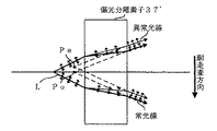
本実施の形態に係る偏光分離素子37は、図17に示すように、結晶光軸が互いに直交する2つの一軸性結晶37A、37Bを張り合わせて構成した、レーザビームLを記録フィルムFの副走査方向に対して常光線及び異常光線に分離するローションプリズムであり、例えば、レーザビームLの入射側に配置される一軸性結晶37Aの結晶光軸がレーザビームLの光軸に平行に設定され、レーザビームLの出射側に配置される一軸性結晶37Bの結晶光軸がレーザビームLの光軸及び副走査方向と直交する方向に設定される。この場合、常光線は偏光分離素子37を直進し、異常光線は偏光分離素子37によって副走査方向に屈折される。
【0188】
なお、偏光分離素子37としては、一軸性結晶37Aの結晶光軸がレーザビームLの光軸に直交すると共に副走査方向に平行に設定され、一軸性結晶37Bの結晶光軸がレーザビームLの光軸及び副走査方向と直交する方向に設定されるウォラストンプリズムを適用してもよい。
【0189】
また、偏光分離素子37は、レーザビームLを必ずしも常光線と異常光線とに分離させる必要はなく、偏光方向の異なる2つの光に分離するものであればよい。
【0190】
一方、本実施の形態に係る偏光方向制御素子34は、図18(A)及び図18(B)に示すように、ガラス板34Bを基台とし、偏光分離素子37の光軸方向上流側に設けられた際に、レーザビームLの一部が透過されると共に、偏光分離素子37により分離される光の偏光方向に対して結晶光軸が略45度傾斜するように1/2波長板34Aを配置して構成したものである。また、ここでは、1/2波長板34A及びガラス板34Bの光が入射される領域の面積比が略1対1となるように、複数の1/2波長板34Aを、所定間隔D毎に各々の両端部(レーザビームLが通過しない部位)をガラス板34Bに接着して構成したものである。
【0191】
このように、本実施の形態に係る偏光方向制御素子34は、1/2波長板34AのレーザビームLが入射される領域と、当該1/2波長板34Aに入射されないレーザビームLの領域、すなわち、ガラス板34BのレーザビームLが入射される領域との面積比が略1対1となるように、複数の1/2波長板34AをレーザビームLの全入射領域において各々所定間隔D毎に配置して構成したものであるが、レーザ記録装置10Cの装置仕様等に基づいて、1/2波長板34A及びガラス板34BのレーザビームLが入射される領域の面積比が、偏光分離素子37によって得られる2つのレーザビームの各々の光量が略同一となるように構成するものとすることもできる。また、1/2波長板34Aを透過したレーザビームLと、透過しなかったレーザビームL(すなわち、ガラス板34Bのみを透過したレーザビームL)の光量が略同一となるように1/2波長板34Aの配置位置を調整して構成するものとすることもできる。なお、これらの偏光方向制御素子の構成は、図18に示されるものと略同一であるので、これらの偏光方向制御素子の他の図示は省略する。
【0192】
ここで、以上のように構成された偏光方向制御素子34を用いない場合と、偏光方向制御素子34を用いた場合の、偏光分離素子37によるレーザビームの分離状態について説明する。まず、図19を参照して、偏光方向制御素子34を用いない場合のレーザビームの分離状態について説明する。
【0193】
図19(A)に示すように、例えば、偏光がe1+e2のレーザビーム(偏光e1に対して45度傾斜した偏光のレーザビーム)が偏光分離素子37に入射した場合は、均等に2つの偏光e1及び偏光e2に分離される。
【0194】
一方、図19(B)に示すように、偏光e1のレーザビームが偏光分離素子37に入射した場合には、偏光e1のレーザビームしか偏光分離素子37から出射されない。従って、この場合は、均等に2つのレーザビームに分離することは困難である。
【0195】
次に、図20を参照して、偏光方向制御素子34を用いた場合のレーザビームの分離状態について説明する。
【0196】
図20(A)に示すように、偏光がe1+e2のレーザビーム(偏光e1に対して45度傾斜した偏光のレーザビーム)がガラス板34Bに入射した場合は、偏光方向が変化することなく透過し、このレーザビームが偏光分離素子37に入射して、均等に2つの偏光e1及び偏光e2に分離される。これに対し、偏光がe1+e2のレーザビームが1/2波長板34Aに入射した場合は、結晶光軸が偏光e1に対して45度傾斜しているため、偏光方向が変化することなく透過し、このレーザビームが偏光分離素子37に入射して、均等に2つの偏光e1及び偏光e2に分離される。
【0197】
一方、図20(B)に示すように、偏光e1のレーザビームがガラス板34Bに入射した場合は、偏光方向が変化することなく透過し、このレーザビームが偏光分離素子37に入射して、偏光e1のみのレーザビームを出射する。これに対し、偏光e1のレーザビームが1/2波長板34Aに入射した場合は、結晶光軸が偏光e1に対して45度傾斜しているため、偏光e1に直交する偏光e2となって出射され、このレーザビームが偏光分離素子37に入射して、偏光e2のみのレーザビームを出射する。従って、空間的には異なる位置となるが、総合的にみてレーザビームを均等に分割することができる。
【0198】
ところで、本実施の形態に係るレーザ記録装置10Cは、図16に示される集光レンズ38の焦点距離fとレーザビームLの波長λとの乗算値f×λを図18に示される間隔c(1/2波長板34Aの配置周期間隔)で除算して得られる値(f×λ)/cが所定値(本実施の形態では、レーザビームLの記録フィルムF上での集光スポットの光強度の半値半幅(図27も参照))以下となるように焦点距離f、波長λ、及び間隔cを決定している。
【0199】
本実施の形態では、レーザビームLの波長λと集光レンズ38の焦点距離fをレーザ記録装置10Cの製造コスト、寸法等の設計条件に応じて予め決定しておき、上記(f×λ)/cが集光スポットの光強度の半値半幅以下となるように間隔cを決定して偏光方向制御素子34を作製するようにしているが、これに限らず、例えば、偏光方向制御素子34を製造コスト等の製造上の条件に応じて間隔cを予め決定して作製し、上記(f×λ)/cが上記半値半幅以下となるようにレーザビームLの波長λと集光レンズ38の焦点距離fの少なくとも一方を決定する形態とすることもできる。
【0200】
なお、本実施の形態に係るレーザ記録装置10Cの制御系の構成は、上記第1実施形態に係るレーザ記録装置10Aと同様(図6参照)であるので、ここでの説明は省略する。
【0201】
次に、以上のように構成されたレーザ記録装置10Cの作用について、図21に示すフローチャートを参照しつつ説明する。
【0202】
まず、作業者は、レーザ記録装置10Cに対して記録する画像の解像度を示す解像度データを入力する(ステップ200)。この解像度データ、及び記録すべき画像の画像データは制御回路52に供給され、制御回路52は、これらのデータに基づいて調整された信号をLD駆動回路54、素子移動モータ駆動回路56及び副走査モータ駆動回路58に供給する。なお、本実施の形態では、上記解像度としてR(dpi)と2・R(dpi)の2種類の解像度で画像を記録できるものとして以下の説明を行う。
【0203】
作業者によって入力された解像度が2・R(dpi)である場合(ステップ202で肯定判定された場合)、素子移動モータ駆動回路56は素子移動モータ40を駆動し、偏光分離素子37がレーザビームLの光路上に位置しないように偏光分離素子37を移動させる(ステップ204)。また、この場合、副走査モータ駆動回路58は副走査モータ16による露光ヘッド12の副走査方向に対する送り間隔Wを上記(11)式のように設定する(ステップ206)。
【0204】
すなわち、解像度が2・R(dpi)である場合、偏光分離素子37をレーザビームLの光路上から外すことによって、レーザビームLを副走査方向に2つのレーザビーム(常光線及び異常光線)に分離しないようにしており、これによってレーザビームLを分離する場合の2倍の解像度を実現している。
【0205】
上述のように偏光分離素子37の移動及び副走査方向に対する送り間隔の設定が終了すると、LD駆動回路54は、画像データに応じて各半導体レーザLDの駆動を制御する(ステップ208)。
【0206】
各半導体レーザLDから射出されたレーザビームLは、コリメータレンズ32によって略平行光束とされた後、偏光方向制御素子34に入射する。偏光方向制御素子34に入射したレーザビームLは、ガラス板34Bに入射したレーザビームについては偏光方向が変更されることなく出射される。また、1/2波長板34Aに入射したレーザビームについては、偏光方向が1/2波長板34Aの結晶光軸に一致する偏光は偏光方向が変更されることなく、偏光方向が上記結晶光軸に一致しない偏光は当該偏光方向と上記結晶光軸とのなす角度に応じた方向に偏光方向が変更されて出射される。
【0207】
そして、この偏光方向制御素子34から出射されたレーザビームLは、集光レンズ38を介してドラム14の記録フィルムFに集光される。
【0208】
この場合、記録フィルムF上には、各々図11(A)に示す強度分布からなるビームスポットS1〜S15(図8(A))が形成される。このビームスポットS1〜S15は、図8(A)に示すように、露光ヘッド12が副走査方向に送り間隔Wのピッチで送られると共に、ドラム14が主走査方向に回転されることにより、解像度が2・R(dpi)となる2次元画像が記録フィルムF上に形成される(ステップ210)。
【0209】
次に、解像度が2・R(dpi)からR(dpi)に変更された場合(ステップ202で否定判定された場合)について説明する。この場合、素子移動モータ駆動回路56は素子移動モータ40を駆動し、偏光分離素子37がレーザビームLの光路上に位置するように偏光分離素子37を移動させる(ステップ212)。また、この場合、副走査モータ駆動回路58は副走査モータ16による露光ヘッド12の副走査方向に対する送り間隔W’を上記(12)式のように設定する(ステップ214)。
【0210】
すなわち、解像度がR(dpi)である場合、偏光分離素子37をレーザビームLの光路上に位置させることによって、偏光分離素子37に入射されたレーザビームLを副走査方向に2つのレーザビーム(常光線及び異常光線)に分離するようにしており、これによってレーザビームLを分離しない場合の2分の1の解像度を実現している。
【0211】
上述のように偏光分離素子37の移動及び副走査方向に対する送り間隔の設定が終了すると、LD駆動回路54は、画像データに応じて各半導体レーザLDの駆動を制御する(ステップ208)。
【0212】
各半導体レーザLDから射出されたレーザビームLは、コリメータレンズ32によって略平行光束とされた後、偏光方向制御素子34に入射する。偏光方向制御素子34に入射したレーザビームLは、ガラス板34Bに入射したレーザビームについては偏光方向が変更されることなく出射される。また、1/2波長板34Aに入射したレーザビームについては、偏光方向が1/2波長板34Aの結晶光軸に一致する偏光は偏光方向が変更されることなく、偏光方向が上記結晶光軸に一致しない偏光は当該偏光方向と上記結晶光軸とのなす角度に応じた方向に偏光方向が変更されて出射される。
【0213】
偏光方向制御素子34から出射されたレーザビームLは偏光分離素子37に供給され、常光線及び異常光線の双方が透過する。そして、この常光線及び異常光線は、集光レンズ38を介してドラム14の記録フィルムFに集光される。
【0214】
この場合、記録フィルムF上には、図11(B)に示す2つの強度分布、すなわち常光線による強度分布と異常光線による強度分布とが副走査方向に合成された状態の強度分布からなるビームスポットS1’〜S15’(図8(B))が形成される。
【0215】
このビームスポットS1’〜S15’は、図8(B)に示すように、露光ヘッド12が副走査方向に送り間隔W’のピッチで送られると共に、ドラム14が主走査方向に回転されることにより、解像度がR(dpi)となる2次元画像が記録フィルムF上に形成される(ステップ210)。
【0216】
このように、記録画像の解像度を2・R(dpi)からR(dpi)に変更した場合、偏光分離素子37をレーザビームLの光路上に挿入するだけでビームスポットS1〜S15をビームスポットS1’〜S15’に容易に拡大することができ、しかも、副走査速度が高速化されるので、高速で画像記録を行うことが可能となる。
【0217】
同様にして、解像度をR(dpi)から2・R(dpi)に変更することができる。
【0218】
上記ステップ200の処理が「課題を解決するための手段」に記載の入力手段に相当する。
【0219】
以上詳細に説明したように、本第3実施形態に係るレーザ記録装置10Cでは、集光レンズ38の焦点距離fとレーザビームLの波長λとの乗算値f×λを間隔cで除算して得られる値(f×λ)/cが所定値以下となるように焦点距離f、波長λ、及び間隔cを決定しているので、レーザビームLの集光スポットと一次回折光との間のずれ量を小さくすることができ、この結果として記録フィルムF上に形成される画像の品質を向上することができる。
【0220】
また、本第3実施形態に係るレーザ記録装置10Cでは、上記所定値としてレーザビームLの記録フィルムF上での集光スポットの半値半幅としているので、一次回折光の影響による画質の劣化を確実に防止することができる。
【0221】
なお、本実施の形態では、上記所定値としてレーザビームLの記録フィルムF上での集光スポットの半値半幅を適用した場合について説明したが、本発明はこれに限定されるものではなく、集光スポットと一次回折光のずれの画質に対する影響は、記録フィルムF上に形成される画像の解像度等によってもある程度左右されるし、要求される画質も一定とは限らないので、上記所定値として上記半値半幅の近傍の値(例えば、当該半値半幅の±10%の値)を適用することもできる。この場合も、本実施の形態とほぼ同様の効果を奏することができる。
【0222】
〔第4実施形態〕
上記第3実施形態では、本発明の偏光分離素子を光が略平行光束となる部位に配設し、2つの光を異なる角度で出射するものとした場合の一形態について説明したが、本第4実施形態では、偏光分離素子を光が発散する部位に配設し、2つの光を当該偏光分離素子による光の分離方向に対する異なる位置から出射するものとした場合の一形態について説明する。
【0223】
まず、図22を参照して、第4実施形態に係るレーザ記録装置10Dの構成について説明する。なお、同図における図16に示されるレーザ記録装置10Cと同一の構成要素には図16と同一の符号を付して、その説明を省略する。
【0224】
同図に示すように、本第4実施形態に係るレーザ記録装置10Dは、偏光分離素子37に代えて一軸性結晶からなる偏光分離素子37’を用いている点と、偏光方向制御素子34及び偏光分離素子37’をファイバーアレイ部30とコリメータレンズ32との間のレーザビームLの発散する部位に配設した点のみが、上記第3実施形態に係るレーザ記録装置10Cと相違している。この場合、偏光分離素子37’の結晶光軸の方向は、レーザビームLの光軸方向と副走査方向との間となるように設定される。
【0225】
本実施の形態に係るレーザ記録装置10Dでは、図22に示されるファイバーアレイ部30のレーザビームLの出射位置と偏光方向制御素子34との間の距離TとレーザビームLの波長λとの乗算値T×λを図18に示される間隔c(1/2波長板34Aの配置周期間隔)で除算して得られる値(T×λ)/cが所定値(本実施の形態では、ファイバーアレイ部30の出射位置でのレーザビームLの光強度の半値半幅)以下となるように距離T、波長λ、及び間隔cを決定している。
【0226】
本実施の形態では、レーザビームLの波長λと距離Tをレーザ記録装置10Dの製造コスト、寸法等の設計条件に応じて予め決定しておき、上記(T×λ)/cが上記半値半幅以下となるように間隔cを決定して偏光方向制御素子34を作製するようにしているが、これに限らず、例えば、偏光方向制御素子34を製造コスト等の製造上の条件に応じて間隔cを予め決定して作製し、上記(T×λ)/cが上記半値半幅以下となるようにレーザビームLの波長λと距離Tの少なくとも一方を決定する形態とすることもできる。
【0227】
解像度をR(dpi)に設定した場合において、偏光方向制御素子34により偏光方向が制御されたレーザビームLは、図23に示すように偏光分離素子37’によって常光線及び異常光線に分離される。この場合、常光線に対する偏光分離素子37’の屈折率は、結晶光軸の方向によらず一定であるため、レーザビームLの光軸上の仮想発光点Poから射出されてコリメータレンズ32に導かれる。一方、異常光線に対する偏光分離素子37’の屈折率は、レーザビームLの入射方向と結晶光軸の方向とによって異なり、結晶光軸がレーザビームLの光軸方向と副走査方向との間に設定されているため、レーザビームLの光軸から副走査方向に所定量変位した仮想発光点Peより射出されてコリメータレンズ32に導かれる。
【0228】
この結果、常光線及び異常光線はコリメータレンズ32、及び集光レンズ38を介して記録フィルムF上の副走査方向に所定量ずれた位置に各々集光されることにより、図8(B)に示すビームスポットS1’〜S15’が得られる。これによって、解像度がR(dpi)の画像を形成することができる。
【0229】
一方、解像度が2・R(dpi)の画像を形成する場合は、偏光分離素子37’をレーザビームLの光路上に位置しないように移動させ、図8(A)に示すビームスポットS1〜S15を得るように制御すればよい。
【0230】
以上詳細に説明したように、本第4実施形態に係るレーザ記録装置10Dでは、ファイバーアレイ部30と偏光方向制御素子34との間の距離TとレーザビームLの波長λとの乗算値T×λを間隔cで除算して得られる値(T×λ)/cが所定値以下となるように距離T、波長λ、及び間隔cを決定しているので、レーザビームLの集光スポットと一次回折光との間のずれ量を小さくすることができ、この結果として記録フィルムF上に形成される画像の画質を向上することができる。
【0231】
また、本第4実施形態に係るレーザ記録装置10Dでは、上記所定値をレーザビームLの出射位置での光強度の半値半幅としているので、一次回折光の影響による画質の劣化を確実に防止することができる。
【0232】
また、上記第3、第4実施形態に係る偏光方向制御素子34は、レーザビームLを偏光方向が互いに直交する2つのレーザビームに分離する偏光分離素子37のレーザビームLの光軸方向上流側に設けられる偏光方向制御素子であって、偏光分離素子37の光軸方向上流側に設けられた際に、レーザビームLの一部が透過されると共に、偏光分離素子37により分離される光の偏光方向に対して結晶光軸が略45度傾斜するように1/2波長板34Aを配置して構成しているので、偏光分離素子37と組み合わせて用いた場合に当該偏光分離素子37によりレーザビームLを等光量で分離することが可能となり、偏光分離素子37を用いたレーザ記録装置における記録画像の画質を向上することができる。
【0233】
また、上記第3、第4実施形態に係る偏光方向制御素子34は、1/2波長板34AのレーザビームLが入射される領域と、1/2波長板34Aに入射されないレーザビームLの領域、すなわち、ガラス板34BのレーザビームLが直接入射される領域との面積比が略1対1となるように構成されているので、分離されたレーザビームの強度分布を均一化することができる。
【0234】
また、上記第3、第4実施形態に係る偏光方向制御素子34は、複数の1/2波長板34AをレーザビームLの全入射領域において各々所定間隔毎に配置して構成しているので、容易に作成することができる。
【0235】
また、上記第3、第4実施形態に係るレーザ記録装置10C、10Dでは、以上のような偏光方向制御素子34を、半導体レーザLDと偏光分離素子37との間に、偏光分離素子37により分離されるレーザビームLの偏光方向に対して1/2波長板34Aの結晶光軸が略45度傾斜するように配置しているので、偏光分離素子37によりレーザビームLを等光量で分離することが可能となり、分離されたレーザビームLにより記録フィルムFに画像を記録する際の当該画像の画質を向上することができる。
【0236】
また、上記第3、第4実施形態に係るレーザ記録装置10C、10Dでは、偏光分離素子37がレーザビームLの光軸上に挿抜されるように当該偏光分離素子37を移動させる素子移動モータ40を備えているので、当該素子移動モータ40により偏光分離素子37を光路上に挿抜することによって、記録フィルムFに画像を記録する際の解像度を容易に変更することができる。
【0237】
更に、上記各実施形態に係るレーザ記録装置10A〜10Dでは、半導体レーザLDをアレイ屈折素子又は偏光分離素子によるレーザビームLの分割(分離)方向に沿って複数配置し、各半導体レーザLDから射出されたレーザビームLを各々アレイ屈折素子又は偏光分離素子によって分割(分離)して記録フィルムFに導くように構成しているので、画像を高速に記録することができる。
【0238】
なお、上記第4実施形態では、偏光方向制御素子34及び偏光分離素子37’をレーザビームが発散する部位に配設した場合について説明したが、本発明はこれに限定されるものではなく、例えば、レーザビームが収束する部位、すなわち、集光レンズ38と記録フィルムFとの間に配設する形態とすることもできる。
【0239】
図24には、この場合のレーザ記録装置の概略構成図(平面図)が示されている。この場合は、偏光方向制御素子34と記録フィルムFとの間の距離Qとレーザビームの波長λとの乗算値Q×λを間隔cで除算して得られる値(Q×λ)/cが所定値以下となるように距離Q、波長λ、及び間隔cを決定すればよい。
【0240】
このとき、上記所定値をレーザビームLの集光スポットでの光強度の半値半幅とすることにより、一次回折光の影響による画質の劣化を確実に防止することができる。
【0241】
また、この場合も、波長λと距離Qをレーザ記録装置の製造コスト、寸法等の設計条件に応じて予め決定しておき、上記(Q×λ)/cがレーザビームLの出射位置での光強度の半値半幅以下となるように間隔cを決定して偏光方向制御素子34を作製する形態や、偏光方向制御素子34を製造コスト等の製造上の条件に応じて間隔cを予め決定して作製し、上記(Q×λ)/cが上記半値半幅以下となるように波長λと距離Qの少なくとも一方を決定する形態等を適用することができる。
【0242】
この場合も、上記第4実施形態と同様の効果を奏することができる。
【0243】
また、上記第4実施形態では、上記所定値としてレーザビームLの出射位置での光強度の半値半幅を適用した場合について説明したが、本発明はこれに限定されるものではなく、集光スポットと一次回折光のずれの画質に対する影響は、記録フィルムF上に形成される画像の解像度等によってもある程度左右されるし、要求される画質も一定とは限らないので、上記所定値として上記半値半幅の近傍の値(例えば、当該半値半幅の±10%の値)を適用することもできる。この場合も、本実施の形態とほぼ同様の効果を奏することができる。
【0244】
また、上記第3、第4実施形態では、素子移動モータ40を偏光分離素子37のみをレーザビームLの光路上に挿抜することができるものとして構成した場合について説明したが、本発明はこれに限定されるものではなく、素子移動モータ40を偏光方向制御素子34及び偏光分離素子37を同時にレーザビームLの光路上に挿抜することができるものとして構成することもできる。この場合も、上記第3、第4実施形態と同様の効果を奏することができる。
【0245】
更に、上記各実施形態では、本発明をマルチビームスキャンを行うレーザ記録装置10A〜10Dに適用した場合について説明したが、本発明はこれに限定されるものではなく、例えば、光源が1つの半導体レーザで構成されたシングルビームスキャンを行うレーザ記録装置に適用することもできる。この場合も、上記各実施形態と同様の効果を奏することができる。
【0246】
【発明の効果】
以上詳細に説明したように、請求項1に記載の露光装置によれば、少なくとも副走査方向についてはブロードエリアで発光する光ビームを射出する光源と、当該光源と記録媒体との間に配置されると共に当該光源から射出された光ビームを略平行光束とする第1レンズ、及び該第1レンズと記録媒体との間に配置されると共に上記光ビームを記録媒体上に集光する第2レンズを含んで構成された集光光学系と、1本の光ビームを2つに分割する単位表面形状を有する屈折部材が対単位でアレイ状に並ぶように構成すると共に、光ビームの分割方向が光源から射出された光ビームのブロードエリア方向と略平行となるように第1レンズと第2レンズとの間に配置されたアレイ屈折素子と、を備えると共に、上記第2レンズの焦点距離fと上記光ビームの波長λとの乗算値f×λを上記屈折部材における光ビームの分割領域の分割方向に対する幅dで除算して得られる値(f×λ)/dが前記光ビームの前記記録媒体上での集光スポットの光強度の半値半幅以下となるように焦点距離f、波長λ、及び幅dを決定しているので、上記光ビームの集光スポットと一次回折光との間のずれ量を小さくすることができ、この結果として記録媒体上に形成される画像の品質を向上することができる、という効果が得られる。
【0247】
また、請求項2に記載の露光装置によれば、少なくとも副走査方向についてはブロードエリアで発光する光ビームを射出する光源と、当該光源と記録媒体との間に配置されると共に当該光源から射出された光ビームを略平行光束とする第1レンズ、及び該第1レンズと記録媒体との間に配置されると共に上記光ビームを記録媒体上に集光する第2レンズを含んで構成された集光光学系と、1本の光ビームを2つに分割する単位表面形状を有する屈折部材が対単位でアレイ状に並ぶように構成すると共に、光ビームの分割方向が光源から射出された光ビームのブロードエリア方向と略平行となるように第2レンズと記録媒体との間に配置されたアレイ屈折素子と、を備えると共に、アレイ屈折素子と記録媒体との間の距離Rと上記光ビームの波長λとの乗算値R×λを上記屈折部材における光ビームの分割領域の分割方向に対する幅dで除算して得られる値(R×λ)/dが前記光ビームの前記記録媒体上での集光スポットの光強度の半値半幅以下となるように距離R、波長λ、及び幅dを決定しているので、上記光ビームの集光スポットと一次回折光との間のずれ量を小さくすることができ、この結果として記録媒体上に形成される画像の品質を向上することができる、という効果が得られる。
【0248】
また、請求項3に記載の露光装置によれば、少なくとも副走査方向についてはブロードエリアで発光する光ビームを射出する光源と、当該光源と記録媒体との間に配置されると共に当該光源から射出された光ビームを略平行光束とする第1レンズ、及び該第1レンズと記録媒体との間に配置されると共に上記光ビームを記録媒体上に集光する第2レンズを含んで構成された集光光学系と、1本の光ビームを2つに分割する単位表面形状を有する屈折部材が対単位でアレイ状に並ぶように構成すると共に、光ビームの分割方向が光源から射出された光ビームのブロードエリア方向と略平行となるように光源と第1レンズとの間に配置されたアレイ屈折素子と、を備えると共に、光源とアレイ屈折素子との間の距離Sと上記光ビームの波長λとの乗算値S×λを上記屈折部材における光ビームの分割領域の分割方向に対する幅dで除算して得られる値(S×λ)/dが前記光ビームの出射位置での光強度の半値半幅以下となるように距離S、波長λ、及び幅dを決定しているので、上記光ビームの集光スポットと一次回折光との間のずれ量を小さくすることができ、この結果として記録媒体上に形成される画像の品質を向上することができる、という効果が得られる。
【0249】
また、請求項4に記載の露光装置によれば、少なくとも副走査方向についてはブロードエリアで発光する光ビームを射出する光源と、当該光源と記録媒体との間に配置されると共に当該光源から射出された光ビームを略平行光束とする第1レンズ、及び該第1レンズと記録媒体との間に配置されると共に上記光ビームを記録媒体上に集光する第2レンズを含んで構成された集光光学系と、上記光ビームを偏光方向が互いに直交する2つの光に分離する偏光分離素子と、当該偏光分離素子により分離される光ビームの偏光方向に対して結晶光軸が45度を含む所定範囲の角度で傾斜するように複数の1/2波長板を、上記光ビームの全入射領域において各々所定間隔cを1周期として配置して構成した偏光方向制御素子と、を備えると共に、上記第2レンズの焦点距離fと上記光ビームの波長λとの乗算値f×λを上記所定間隔cで除算して得られる値(f×λ)/cが前記光ビームの前記記録媒体上での集光スポットの光強度の半値半幅以下となるように焦点距離f、波長λ、及び所定間隔cを決定しているので、上記光ビームの集光スポットと一次回折光との間のずれ量を小さくすることができ、この結果として記録媒体上に形成される画像の品質を向上することができる、という効果が得られる。
【0250】
また、請求項5に記載の露光装置によれば、少なくとも副走査方向についてはブロードエリアで発光する光ビームを射出する光源と、当該光源と記録媒体との間に配置されると共に当該光源から射出された光ビームを略平行光束とする第1レンズ、及び該第1レンズと記録媒体との間に配置されると共に上記光ビームを記録媒体上に集光する第2レンズを含んで構成された集光光学系と、上記光ビームを偏光方向が互いに直交する2つの光に分離する偏光分離素子と、当該偏光分離素子により分離される光ビームの偏光方向に対して結晶光軸が45度を含む所定範囲の角度で傾斜するように複数の1/2波長板を、上記光ビームの全入射領域において各々所定間隔cを1周期として配置して構成した偏光方向制御素子と、を備えると共に、偏光方向制御素子と記録媒体との間の距離Qと上記光ビームの波長λとの乗算値Q×λを上記所定間隔cで除算して得られる値(Q×λ)/cが前記光ビームの集光スポットでの光強度の半値半幅以下となるように距離Q、波長λ、及び所定間隔cを決定しているので、上記光ビームの集光スポットと一次回折光との間のずれ量を小さくすることができ、この結果として記録媒体上に形成される画像の品質を向上することができる、という効果が得られる。
【0251】
更に、請求項6に記載の露光装置によれば、少なくとも副走査方向についてはブロードエリアで発光する光ビームを射出する光源と、当該光源と記録媒体との間に配置されると共に当該光源から射出された光ビームを略平行光束とする第1レンズ、及び該第1レンズと記録媒体との間に配置されると共に上記光ビームを記録媒体上に集光する第2レンズを含んで構成された集光光学系と、上記光ビームを偏光方向が互いに直交する2つの光に分離する偏光分離素子と、当該偏光分離素子により分離される光ビームの偏光方向に対して結晶光軸が45度を含む所定範囲の角度で傾斜するように複数の1/2波長板を上記光ビームの全入射領域において各々所定間隔cを1周期として配置して構成した偏光方向制御素子と、を備えると共に、上記光源と上記偏光方向制御素子との間の距離Tと上記光ビームの波長λとの乗算値T×λを上記所定間隔cで除算して得られる値(T×λ)/cが前記光ビームの出射位置での光強度の半値半幅以下となるように距離T、波長λ、及び所定間隔cを決定しているので、上記光ビームの集光スポットと一次回折光との間のずれ量を小さくすることができ、この結果として記録媒体上に形成される画像の品質を向上することができる、という効果が得られる。
【図面の簡単な説明】
【図1】第1実施形態に係るレーザ記録装置10Aの概略構成図(平面図)である。
【図2】実施の形態に係るファイバーアレイ部30の概略構成図(側面図)である。
【図3】第1実施形態に係るアレイ屈折素子36の構成を示す概略構成図(平面図)である。
【図4】実施の形態に係るレーザ記録装置における集光スポットの状態を示す図であり、(A)はアレイ屈折素子又は偏光分離素子をレーザビームLの光路上に位置させない場合に記録フィルムF上に形成される集光スポットの状態を、(B)はアレイ屈折素子又は偏光分離素子をレーザビームLの光路上に位置させた場合に記録フィルムF上に形成される集光スポットの状態を、各々示す概略図である。
【図5】第1実施形態に係るレーザ記録装置10Aの各種パラメータを示す概略図(平面図)である。
【図6】実施の形態に係るレーザ記録装置の制御系の構成を示すブロック図である。
【図7】第1、第2実施形態に係るレーザ記録装置において、解像度に応じて画像記録を行う場合の処理の流れを示すフローチャートである。
【図8】実施の形態に係るレーザ記録装置による記録フィルムF上でのビームスポットの状態を示す概略図である。
【図9】第1実施形態に係るレーザ記録装置10Aの作用の説明に供する概略図(平面図)である。
【図10】本発明のアレイ屈折素子の他の構成例を示す概略構成図(平面図)である。
【図11】集光点におけるレーザビームの強度分布の状態例を示すグラフである。
【図12】第2実施形態に係るレーザ記録装置10Bの概略構成図(平面図)である。
【図13】(A)は第2実施形態に係るレーザ記録装置10Bの作用の説明に供する概略図(平面図)であり、(B)は第2実施形態に係るアレイ屈折素子36’ の構成及び作用の説明に供する概略図(平面図)である。
【図14】第2実施形態に係るレーザ記録装置10Bの各種パラメータを示す概略図(平面図)である。
【図15】他のレーザ記録装置の構成及び各種パラメータを示す概略図(平面図)である。
【図16】第3実施形態に係るレーザ記録装置10Cの概略構成図(平面図)である。
【図17】第3実施形態に係る偏光分離素子37の構成及び作用の説明に供する概略図(平面図)である。
【図18】(A)は第3、第4実施形態に係る偏光方向制御素子34の概略構成図(正面図及び側面図)であり、(B)は偏光方向制御素子34の結晶光軸の方向を示す概略図である。
【図19】第3、第4実施形態に係るレーザ記録装置において偏光方向制御素子34を用いない場合の偏光分離素子37によるレーザビームの分離状態を示す概略図である。
【図20】第3、第4実施形態に係るレーザ記録装置において偏光方向制御素子34を用いた場合の偏光分離素子37によるレーザビームの分離状態を示す概略図である。
【図21】第3、第4実施形態に係るレーザ記録装置において、解像度に応じて画像記録を行う場合の処理の流れを示すフローチャートである。
【図22】第4実施形態に係るレーザ記録装置10Dの概略構成図(平面図)である。
【図23】第4実施形態に係る偏光分離素子37’の作用の説明に供する概略図(平面図)である。
【図24】他のレーザ記録装置の構成及び各種パラメータを示す概略図(平面図)である。
【図25】本発明の原理の説明に供する概略図である。
【図26】本発明の効果の説明に供する概略図である。
【図27】集光スポットの半値半幅を示すグラフである。
【図28】従来技術の原理の説明に供する概略図である。
【図29】回折光の発生メカニズムの説明に供する概略図である。
【図30】回折光の発生メカニズムの説明に供するグラフである。
【符号の説明】
10A、10B、10C、10D レーザ記録装置
12 露光ヘッド
14 ドラム
16 副走査モータ
20 光ファイバー
30 ファイバーアレイ部
32 コリメータレンズ(第1レンズ)
34 偏光方向制御素子
34A 1/2波長板
34B ガラス板
36 アレイ屈折素子
36A、36B 偏角プリズム
36’ アレイ屈折素子
37 偏光分離素子
37’ 偏光分離素子
38 集光レンズ(第2レンズ)
40 素子移動モータ(移動手段)
L レーザビーム
LD 半導体レーザ(光源)
F 記録フィルム(記録媒体)[0001]
BACKGROUND OF THE INVENTION
The present invention relates to an exposure apparatus, and more particularly to an exposure apparatus that forms an image on a recording medium by scanning exposure.
[0002]
[Prior art]
Conventionally, a drum having a photosensitive material (recording medium) mounted on its outer peripheral surface is rotated in the main scanning direction, and a laser beam modulated in accordance with image data of an image to be recorded on the photosensitive material is used in the main scanning direction. An exposure recording apparatus is used in which a two-dimensional image is recorded on the photosensitive material by scanning in the sub-scanning direction orthogonal to the above.
[0003]
In this type of exposure recording apparatus, in order to record an image with a low resolution, the spot diameter of the laser beam on the surface of the photosensitive material is enlarged and the recording pitch in the sub-scanning direction is increased or the spot diameter is increased. There has been employed a method of repeatedly recording pixels composed of the same image data as much as the resolution is lowered without changing the size and the recording pitch. On the other hand, when recording an image with a high resolution, the opposite method has been adopted.
[0004]
However, in order to enlarge or reduce the spot diameter of the laser beam in this way, it is necessary to drive the lens of the optical system using a drive mechanism, so that the apparatus becomes larger and the cost increases. There was a problem that. In addition, when the resolution is lowered by repeatedly recording pixels made of the same image data by the amount of the lowered resolution, the recording speed in the sub-scanning direction is constant, so that the recording speed cannot be improved. was there.
[0005]
In order to solve these problems, the technique described in Japanese Patent Laid-Open No. 2000-284206 by the applicant of the present invention divides the light emitted from the light source into a plurality of recording media using a condensing optical system. A plurality of condensing point generating means for generating a plurality of condensing points in the sub scanning direction of the recording medium, and a sub scanning control means for controlling a recording interval in the sub scanning direction according to the resolution. In addition, when the light emitted from the light source is condensed on the recording medium via the condensing optical system and an image is recorded, the sub-scanning direction is generated by the plurality of condensing point generating means according to the resolution of the recorded image. The size of the beam spot is adjusted by controlling the number of condensing points generated by dividing into two, and the image according to the resolution can be efficiently obtained by adjusting the recording interval of the beam spot in the sub-scanning direction. As possible to record It was.
[0006]
In this technique, a polarizing optical element constituted by a uniaxial crystal or a declination prism is applied as the plurality of condensing point generating means.
[0007]
However, in the technique described in Japanese Patent Laid-Open No. 2000-284206, when a polarizing optical element composed of a uniaxial crystal is used as a plurality of focusing points generating means, the uniaxial crystal is expensive and expensive. There was a problem of becoming.
[0008]
Further, in the technique described in the publication, when a declination prism is applied as a plurality of condensing point generating means, there is a problem that the image quality of a recorded image may be deteriorated.
[0009]
That is, in the technique described in the publication, when a declination prism is applied as the plurality of condensing point generation means, the optical axis direction (from the focal position of the laser beam divided by the declination prism and collected by the condensing lens ( The depth of the laser beam at a position shifted back and forth becomes asymmetric with respect to the optical axis direction.
[0010]
This is because the light divided by the declination prism is condensed by the condenser lens at different positions in the division direction of the focal position, so that the divided lights are separated from each other when the light incident side is viewed from the focal position. This is a phenomenon that occurs when the divided light approaches and intersects when viewed from the focal point, and the separated position of the recording medium in the depth direction. Even if the permissible range is reduced and the displacement of the arrangement position in the depth direction is slight, the image quality of the recorded image on the recording medium may deteriorate.
[0011]
In order to solve these problems, the technique described in Japanese Patent Application No. 2001-310537 by the applicant of the present invention is an exposure apparatus that forms an image on a recording medium by scanning exposure, and is at least a sub-scan. With respect to the direction, a light source that emits a light beam that emits light in a broad area, a condensing optical system that condenses the light beam emitted from the light source on the recording medium, and an exposure apparatus that has one light beam. In an array refracting element configured such that refractive members having unit surface shapes that are divided into two are arranged in an array in pairs, the dividing direction of the light beam is substantially the same as the broad area direction of the light beam emitted from the light source. They were arranged in parallel.
[0012]
As a result, the light beam divided into two by the array pair of array refractive elements is composed of light corresponding to the number of array pairs. Accordingly, since one condensing spot is formed by the number of condensing beams of the array pairs, when the divided light beams are superposed by shifting the condensing spots by two at the focal position by the condensing lens, the focal position When looking at the incident side of the light beam from the focal point and when looking at the outgoing side of the light beam from the focal position, the blurring of each light beam is symmetric with respect to the optical axis direction. Can be improved.
[0013]
The array refracting element can be made of any material as long as it can split the light beam into two, and is therefore required when the light beam is separated according to the polarization direction. A uniaxial crystal is not necessarily used, and can be configured at low cost.
[0014]
By the way, for the purpose of improving the recording speed, each laser beam emitted from a plurality of light sources is guided to a single exposure head by an optical fiber, and the end of the exit of the laser beam in each optical fiber is connected to the exposure head. There is an exposure recording apparatus that is arranged side by side in the scanning direction and simultaneously performs exposure with a plurality of laser beams emitted from the plurality of light sources.
[0015]
When the technique described in Japanese Patent Laid-Open No. 2000-284206 is applied to this type of exposure recording apparatus, since one laser beam can be divided and exposed, the recording speed can be further increased. Improvement is possible.
[0016]
However, in such an exposure recording apparatus using an optical fiber, the polarization direction of the laser beam emitted from the optical fiber changes every moment due to external force displacement (vibration displacement, pressure displacement, torsional displacement, temperature displacement, etc.) applied to the optical fiber. In this case, there is a problem in that the image quality of the recorded image deteriorates because the light quantity of the laser beams divided into a plurality competes and the condensing spot becomes an unstable shape. there were.
[0017]
Therefore, in order to solve this problem, in the technique described in Japanese Patent Application No. 2001-201407 by the applicant of the present invention, the light source that emits light and the light emitted from the light source are condensed on the recording medium. An exposure apparatus comprising a condensing optical system that performs the above and a polarization separation element that separates the light into two light beams whose polarization directions are orthogonal to each other, and the polarization separation element between the light source and the polarization separation element. A plurality of half-wave plates are arranged at predetermined intervals in the entire incident region of the light beam so that the crystal optical axis is inclined at an angle within a predetermined range including 45 degrees with respect to the polarization direction of the light beam separated by The polarization direction control element arranged and configured has been arranged.
[0018]
The crystal optical axis is also referred to as an “optical axis”, but in this specification, it is described as “crystal optical axis”. Further, the angle in the predetermined range including 45 degrees is ideally 45 degrees, but in an apparatus to which the polarization direction control element is applied, an angle within a range allowed for manufacturing the polarization direction control element. It means an angle within various allowable ranges such as an allowable range.
[0019]
Here, the principle of the present technology will be briefly described with reference to FIG. Here, a case will be described in which the polarization direction control element of the present technology is configured by combining a half-wave plate and a transparent parallel plate that does not significantly affect the polarization direction of transmitted light. As shown in the figure, when the polarization direction of the light separated by the polarization separation element is (x, y), the direction of the crystal optical axis of the half-wave plate in the polarization direction control element is (x, y). It is assumed that the polarization direction control element is arranged so as to be inclined by 45 degrees with respect to the direction. In this case, the coordinate system of the crystal optical axis in the half-wave plate is (X, Y). Further, here, on the premise that there is no difference in light transmittance between the transparent parallel plate and the half-wave plate in the polarization direction control element or is negligibly small, the amount of light incident on the half-wave plate and It is assumed that the polarization direction control element is arranged at a position where the light amount is distributed so that the ratio with respect to the light amount of the incident light is 1: 1.
[0020]
When the electric field vector α of the light incident on the polarization direction control element is α = (a, b), and the light incident on the half-wave plate is considered, the (x, y) coordinate system is rotated by 45 degrees. Where A is the matrix, B is the matrix that delays the ½ wavelength phase of the Y coordinate light, and C is the matrix that is rotated −45 degrees and returned to the original (x, y) coordinate system, as follows: Represented.
[0021]
[Expression 1]
Therefore, the electric field vector β of the light after passing through the half-wave plate is expressed as follows.
[0023]
[Expression 2]
Since α and β are set so as to be distributed 1: 1 as the light amount distribution, the respective light amounts Iα and Iβ are expressed as follows.
[0025]
[Equation 3]
Therefore, the light quantity I when the respective lights are added is as follows.
[0027]
[Expression 4]
As a result, when the light that has passed through the half-wave plate and the light that has not passed through are added together, the light separated in the polarization directions of x and y by the polarization separation element is separated by equal amounts of light. Which indicates that.
[0029]
Here, the transparent parallel plate provided in the polarization direction control element is not necessarily required, and other members (for example, ND (Neutral Density) filters) that do not greatly affect the polarization direction of incident light are transparent. It can also be applied in place of a parallel plate, and without these members, it is possible to have a blank state.
[0030]
Based on the above principle, the polarization direction control element in the technique described in Japanese Patent Application No. 2001-201407 is upstream of the light axis direction of the polarization separation element that separates the light into two lights whose polarization directions are orthogonal to each other. A polarization direction control element provided, wherein when provided on the upstream side in the optical axis direction of the polarization separation element, a part of the light is transmitted and the polarization direction of the light separated by the polarization separation element Since the half-wave plate is arranged so that the crystal optical axis is inclined at an angle within a predetermined range including 45 degrees, the polarization separation element is used when used in combination with the polarization separation element. It becomes possible to separate the light with equal light amount, and the image quality of the recorded image in the exposure recording apparatus using the polarization separating element can be improved.
[0031]
[Problems to be solved by the invention]
However, in the technique of the above Japanese Patent Application No. 2001-310537, diffracted light is generated in the split portion of the light beam in the array refracting element. As a result, there is a problem that the quality of the image formed on the recording medium is deteriorated.
[0032]
Also in the technique of Japanese Patent Application No. 2001-201407, diffracted light is generated at the edge portion of the half-wave plate constituting the polarization direction control element. There is a problem that the shape is deteriorated, and as a result, the quality of the image formed on the recording medium is deteriorated.
[0033]
Here, the generation mechanism of the diffracted light will be described. Here, diffracted light when a plurality of refractive member pairs for splitting a light beam are arranged periodically will be described.
[0034]
In this case, since the light beam is refracted in two directions by a plurality of pairs of refracting members, considering only the light beam emitted in one direction, the light beam transmitted through the refracting member is as shown in FIG. It exhibits the same characteristics as when passing through a periodic aperture grating.
[0035]
Therefore, it is only necessary to solve the diffraction equation when light passes through the periodic aperture grating. The intensity distribution I (p) of diffracted light when uniform light is incident on the periodic aperture grating is expressed by the following equation (1). The diffraction angle pn (rad) of the nth order diffracted light is expressed by the following equation (2).
[0036]
[Equation 5]
[Formula 6]
Where N is the number of the periodic aperture grating (refractive member), k is the wave number of light, d is the width (mm) of the periodic aperture grating (refractive member), s is the aperture width (mm), and p is the diffraction angle (rad). , N is the order of the diffracted light, and λ is the wavelength (mm) of the incident light.
[0039]
Here, as an example, FIG. 30 shows a graph when the following conditions are solved. In the figure, the horizontal axis represents the diffraction angle p, and the vertical axis represents the light intensity I (p).
[0040]
(conditions)
Periodic aperture grating width d = 3 (mm), aperture width s = 1.5 (mm), light wavelength λ = 0.83 (μm)
Further, the diffraction angle p1 of the first-order diffracted light at this time is as follows.
[0041]
p1 = 2.8 × 10 -Four (Rad)
As shown in FIG. 30, the light intensity I of the first-order diffracted light in this case is as large as about 40% with respect to the 0th-order light. It can be seen that the effect is remarkably large. Therefore, when the amount of deviation between the focused spot and the first-order diffracted light is large, the quality of the image formed on the recording medium is significantly deteriorated.
[0042]
The present invention has been made to solve the above problems, and an object thereof is to provide an exposure apparatus capable of improving the quality of an image formed on a recording medium.
[0043]
[Means for Solving the Problems]
In order to achieve the above object, an exposure apparatus according to
[0044]
Here, the principle of the present invention will be described with reference to the drawings. FIG. 25 shows a case where a light beam emitted from a light source having a broad light emitting surface is re-imaged by a condenser lens having a focal length f after passing through the above-described periodic aperture grating (see also FIG. 29). A schematic diagram of is shown. In this case, as shown in the figure, the amount of shift between the central positions of the light spot and the first-order diffracted light is expressed by p1 × f.
[0045]
The diffraction angle p1 of the first-order diffracted light is expressed by the following equation (3) from the above equation (2).
[0046]
[Expression 7]
Therefore, the shift amount between the center positions of the focused spot and the first-order diffracted light is expressed by the following equation (4).
[0048]
[Equation 8]
When this deviation amount is large, the visibility of the first-order diffracted light is large as shown in FIG. 26A as an example, so that the quality of the image formed on the recording medium is significantly deteriorated. When the amount of deviation is small, the visibility of the first-order diffracted light is small as shown in FIG. 26B as an example. Therefore, an image formed on the recording medium compared with the case where the amount of deviation is large. Can improve the quality.
[0050]
Therefore, it is preferable in terms of image quality to reduce the amount of deviation between the focused spot and the first-order diffracted light, but for this purpose, the focal length f, The wavelength λ and the width d of the periodic aperture grating may be determined. The width d of the periodic aperture grating here corresponds to the width d of the light beam splitting region in the refractive member of the present invention with respect to the splitting direction.
[0051]
Based on the principle as described above, according to the exposure apparatus of the first aspect, at least in the sub-scanning direction, the light beam emitted from the light source that emits the light beam that emits light in the broad area is transmitted by the condensing optical system. The pair of refractive members having a unit surface shape that divides one light beam into two when the first lens is made into a substantially parallel light beam and then condensed on the recording medium by the second lens. It is configured to be arranged in an array, and is arranged between the first lens and the second lens so that the light beam splitting direction is substantially parallel to the broad area direction of the light beam emitted from the light source. The light is divided in the broad area direction of the light beam, that is, the sub-scanning direction by the array refracting element. The light source includes various semiconductor lasers. The first lens includes various collimator lenses, and the second lens includes various condenser lenses.
[0052]
Here, in the first aspect of the present invention, the multiplication value f × λ of the focal length f of the second lens and the wavelength λ of the light beam is set to a light beam dividing region in the refractive member constituting the array refracting element. The value (f × λ) / d obtained by dividing by the width d with respect to the dividing direction of To be described later The focal length f, wavelength λ, and width d are determined so as to be equal to or less than a predetermined value.
[0053]
As described above, according to the exposure apparatus of the first aspect, at least in the sub-scanning direction, the light source that emits the light beam that emits light in the broad area, and the light source disposed between the light source and the recording medium. A first lens that converts the light beam emitted from the light beam into a substantially parallel light beam, and a second lens that is disposed between the first lens and the recording medium and condenses the light beam on the recording medium. The condensing optical system and a refractive member having a unit surface shape that divides one light beam into two are arranged in an array in pairs, and the light beam splitting direction is emitted from the light source. And an array refracting element disposed between the first lens and the second lens so as to be substantially parallel to the broad area direction of the light beam, and the focal length f of the second lens and the light beam Wavelength λ The multiplier f × a value obtained by dividing the width d of the lambda for the dividing direction of the divided region of the light beam in the refracting member (f × lambda) / d To be described later Since the focal length f, the wavelength λ, and the width d are determined so as to be less than or equal to predetermined values, the amount of deviation between the focused spot of the light beam and the first-order diffracted light can be reduced. As a result, As a result, the quality of the image formed on the recording medium can be improved.
[0054]
On the other hand, in order to achieve the above object, an exposure apparatus according to
[0055]
That is, the exposure apparatus according to the second aspect has substantially the same configuration as the exposure apparatus according to the first aspect, except that the array refracting element is disposed between the second lens and the recording medium. This is different from the invention described in
[0056]
In this case, the diffraction angle p1 of the first-order diffracted light is the same as that in the equation (3), but the shift amount between the central positions of the focused spot and the first-order diffracted light is expressed by the following equation (5).
[0057]
[Equation 9]
Therefore, in order to reduce the deviation amount between the focused spot and the first-order diffracted light, the distance R, the wavelength λ, and the width d are determined so that the value represented by the right side of the equation (5) is reduced. In the exposure apparatus according to
[0059]
The light source of the present invention includes various semiconductor lasers, the first lens of the present invention includes various collimator lenses, and the second lens of the present invention includes various condenser lenses.
[0060]
As described above, according to the exposure apparatus of the second aspect, at least in the sub-scanning direction, the light source that emits the light beam that emits light in the broad area is disposed between the light source and the recording medium, and the light source. A first lens that converts the light beam emitted from the light beam into a substantially parallel light beam, and a second lens that is disposed between the first lens and the recording medium and condenses the light beam on the recording medium. The condensing optical system and a refractive member having a unit surface shape that divides one light beam into two are arranged in an array in pairs, and the light beam splitting direction is emitted from the light source. And an array refracting element disposed between the second lens and the recording medium so as to be substantially parallel to the direction of the broad area of the light beam, and the distance R between the array refracting element and the recording medium Light bee Multiplication value R × value obtained by dividing the width to division direction of the divided region of the light beam d in the refractive member lambda of the wavelength lambda of (R × lambda) / d is To be described later Since the distance R, the wavelength λ, and the width d are determined so as to be equal to or less than the predetermined values, the amount of deviation between the focused spot of the light beam and the first-order diffracted light can be reduced, and as a result The quality of the image formed on the recording medium can be improved.
[0061]
By the way, according to an experiment by the inventors of the present invention, when the amount of deviation between the focused spot and the first-order diffracted light exceeds the half-width of the focused spot shown in FIG. As a result, it has been found that there is a problem in image quality.
[0062]
Therefore, the predetermined value in the invention according to
[0063]
As a result, it is possible to reliably prevent deterioration in image quality due to the influence of the first-order diffracted light.
[0064]
Note that the influence of the deviation between the focused spot and the first-order diffracted light on the image quality depends to some extent on the resolution of the image formed on the recording medium and the required image quality is not always constant. The value is not limited to the above half-width, but may be a value near the half-width (for example, a value of ± 10% of the half-width).
[0065]
On the other hand, in order to achieve the above object, an exposure apparatus according to
[0066]
That is, the exposure apparatus according to the third aspect has substantially the same configuration as the exposure apparatus according to the first aspect, and only the point that the array refracting element is disposed between the light source and the first lens is charged. This is different from the invention described in
[0067]
In this case, the diffraction angle p1 of the first-order diffracted light is the same as that in the equation (3), but the shift amount between the central positions of the focused spot and the first-order diffracted light is expressed by the following equation (6).
[0068]
[Expression 10]
Therefore, in order to reduce the shift amount between the focused spot and the first-order diffracted light, the distance S, the wavelength λ, and the width d are determined so that the value represented by the right side of the equation (6) is reduced. In the exposure apparatus according to
[0070]
The light source of the present invention includes various semiconductor lasers, the first lens of the present invention includes various collimator lenses, and the second lens of the present invention includes various condenser lenses.
[0071]
Thus, according to the exposure apparatus of the third aspect, at least in the sub-scanning direction, the light source that emits the light beam that emits light in the broad area, and the light source disposed between the light source and the recording medium. A first lens that converts the light beam emitted from the light beam into a substantially parallel light beam, and a second lens that is disposed between the first lens and the recording medium and condenses the light beam on the recording medium. The condensing optical system and a refractive member having a unit surface shape for dividing one light beam into two are arranged in an array in pairs, and the light beam splitting direction is emitted from the light source. And an array refracting element disposed between the light source and the first lens so as to be substantially parallel to the broad area direction of the light beam, and a distance S between the light source and the array refracting element and the light beam. Wavelength The multiplication value S × value obtained by dividing the width d of the lambda for the dividing direction of the divided region of the light beam in the refracting member (S × lambda) / d with To be described later Since the distance S, the wavelength λ, and the width d are determined so as to be equal to or less than the predetermined values, the amount of deviation between the focused spot of the light beam and the first-order diffracted light can be reduced, and as a result The quality of the image formed on the recording medium can be improved.
[0072]
By the way, according to an experiment by the inventors of the present invention, if the amount of deviation between the focused spot and the first-order diffracted light exceeds the half width at the light beam emission position, the influence of the first-order diffracted light on the focused spot increases. Was also found to be a problem.
[0073]
Therefore, the predetermined value in the invention according to
[0074]
As a result, it is possible to reliably prevent deterioration in image quality due to the influence of the first-order diffracted light.
[0075]
Note that the influence of the deviation between the focused spot and the first-order diffracted light on the image quality depends to some extent on the resolution of the image formed on the recording medium and the required image quality is not always constant. The value is not limited to the above half-width, but may be a value near the half-width (for example, a value of ± 10% of the half-width).
[0076]
The exposure apparatus according to any one of
[0077]
Thereby, the resolution information indicating the resolution of the image formed on the recording medium by the scanning exposure is input by the input means, and the array of the present invention is used when the resolution indicated by the resolution information is the predetermined first resolution. The array refracting element is positioned on the optical axis when the refracting element is retracted from the optical axis of the light beam emitted from the light source and the resolution indicated by the resolution information is the second resolution lower than the first resolution. The array refracting element is moved by the moving means.
[0078]
Therefore, in this way, when the resolution information indicating the resolution of the image formed on the recording medium by the scanning exposure is input, and the resolution indicated by the resolution information is the predetermined first resolution, the array refracting element is When the resolution indicated by the resolution information is retracted from the optical axis of the light beam emitted from the light source and the second resolution is lower than the first resolution, the array refracting element is positioned on the optical axis. Since the array refracting element is moved, the resolution at the time of recording an image on the recording medium can be easily changed only by inputting resolution information.
[0079]
Furthermore, the exposure apparatus according to any one of
[0080]
On the other hand, in order to achieve the above object, an exposure apparatus according to
[0081]
According to the exposure apparatus of
[0082]
Here, in the invention according to
[0083]
With this configuration, in the exposure apparatus according to
[0084]
In the case of the exposure apparatus configured as described above, the width d of the periodic aperture grating shown in FIG. 29 corresponds to the predetermined interval c of the present invention, so that the diffraction angle p1 of the first-order diffracted light generated in the polarization direction control element is It is expressed by the following formula (7) from the formula (2).
[0085]
[Expression 11]
Therefore, the shift amount between the center positions of the focused spot and the first-order diffracted light is expressed by the following equation (8).
[0087]
[Expression 12]
Therefore, in order to reduce the amount of deviation between the focused spot and the first-order diffracted light, the focal length f, the wavelength λ, and the predetermined interval c are determined so that the value represented by the right side of the equation (8) becomes small. In the exposure apparatus according to
[0089]
As described above, according to the exposure apparatus of the fourth aspect, the light source that emits the light beam that emits light in the broad area at least in the sub-scanning direction, and the light source disposed between the light source and the recording medium. A first lens that converts the light beam emitted from the light beam into a substantially parallel light beam, and a second lens that is disposed between the first lens and the recording medium and condenses the light beam on the recording medium. A converging optical system, a polarization separation element that separates the light beam into two light beams whose polarization directions are orthogonal to each other, and a crystal optical axis of 45 with respect to the polarization direction of the light beam separated by the polarization separation element. A polarization direction control element comprising a plurality of half-wave plates arranged so as to be inclined at an angle within a predetermined range including degrees, with each predetermined interval c being one period in the entire incident region of the light beam. Together with The second lens focal length f and the beam multiplier f × lambda value obtained by dividing the predetermined distance c between the wavelength lambda of (f × λ) / c is To be described later Since the focal length f, the wavelength λ, and the predetermined interval c are determined so as to be less than or equal to a predetermined value, the amount of deviation between the focused spot of the light beam and the first-order diffracted light can be reduced. As a result, the quality of the image formed on the recording medium can be improved.
[0090]
On the other hand, in order to achieve the above object, an exposure apparatus according to
[0091]
In other words, the exposure apparatus according to the fifth aspect has substantially the same configuration as the exposure apparatus according to the fourth aspect, and the polarization direction control element and the polarization separation element are disposed between the second lens and the recording medium. This is different from the invention described in
[0092]
In this case, the diffraction angle p1 of the first-order diffracted light is the same as that in the equation (7), but the shift amount between the central positions of the focused spot and the first-order diffracted light is expressed by the following equation (9).
[0093]
[Formula 13]
Therefore, in order to reduce the amount of deviation between the focused spot and the first-order diffracted light, the distance Q, the wavelength λ, and the predetermined interval c are determined so that the value represented by the right side of Equation (9) is reduced. Therefore, in the exposure apparatus according to
[0095]
The light source of the present invention includes various semiconductor lasers, the first lens of the present invention includes various collimator lenses, and the second lens of the present invention includes various condenser lenses. The polarization separation element includes various prisms such as a lotion prism and a Wollaston prism.
[0096]
Thus, according to the exposure apparatus of the fifth aspect, at least in the sub-scanning direction, the light source that emits the light beam that emits light in the broad area is disposed between the light source and the recording medium, and the light source A first lens that converts the light beam emitted from the light beam into a substantially parallel light beam, and a second lens that is disposed between the first lens and the recording medium and condenses the light beam on the recording medium. A converging optical system, a polarization separation element that separates the light beam into two light beams whose polarization directions are orthogonal to each other, and a crystal optical axis of 45 with respect to the polarization direction of the light beam separated by the polarization separation element. A polarization direction control element comprising a plurality of half-wave plates arranged so as to be inclined at an angle within a predetermined range including degrees, with each predetermined interval c being one period in the entire incident region of the light beam. Together with , The distance Q and the light beam multiplied value Q × a value obtained by dividing by the predetermined interval c λ (Q × λ) / c of the wavelength lambda of between the polarization direction control element and the recording medium To be described later Since the distance Q, the wavelength λ, and the predetermined interval c are determined so as to be less than or equal to a predetermined value, the amount of deviation between the focused spot of the light beam and the first-order diffracted light can be reduced. As a result, As a result, the quality of the image formed on the recording medium can be improved.
[0097]
As described above, when the amount of deviation between the focused spot and the first-order diffracted light exceeds the half width at half maximum of the focused spot, the influence of the first-order diffracted light on the focused spot is increased. Therefore, the predetermined value in the invention according to
[0098]
As a result, it is possible to reliably prevent deterioration in image quality due to the influence of the first-order diffracted light.
[0099]
In this case as well, the influence of the deviation between the focused spot and the first-order diffracted light on the image quality depends to some extent on the resolution of the image formed on the recording medium, and the required image quality is not always constant. Therefore, the predetermined value is not limited to the half width at half maximum, but may be a value in the vicinity of the half width at half maximum (for example, a value of ± 10% of the half width at half maximum).
[0100]
On the other hand, in order to achieve the above object, an exposure apparatus according to
[0101]
That is, the exposure apparatus according to the sixth aspect has substantially the same configuration as the exposure apparatus according to the fourth aspect, and the polarization direction control element and the polarization separation element are disposed between the light source and the first lens. This is different from the invention described in
[0102]
In this case, the diffraction angle p1 of the first-order diffracted light is the same as in the equation (7), but the shift amount between the central positions of the focused spot and the first-order diffracted light is expressed by the following equation (10).
[0103]
[Expression 14]
Therefore, in order to reduce the amount of deviation between the focused spot and the first-order diffracted light, the distance T, the wavelength λ, and the predetermined interval c are determined so that the value represented by the right side of Equation (10) is reduced. Therefore, in the exposure apparatus according to the sixth aspect, the value (T × λ) / c obtained by dividing the multiplication value T × λ of the distance T and the wavelength λ by the predetermined interval c is as follows. To be described later The distance T, the wavelength λ, and the predetermined interval c are determined so as to be equal to or less than a predetermined value.
[0105]
The light source of the present invention includes various semiconductor lasers, the first lens of the present invention includes various collimator lenses, and the second lens of the present invention includes various condenser lenses. The polarization separation element includes various prisms such as a lotion prism and a Wollaston prism.
[0106]
As described above, according to the exposure apparatus of the sixth aspect, the light source that emits the light beam that emits light in the broad area at least in the sub-scanning direction, and the light source disposed between the light source and the recording medium. A first lens that converts the light beam emitted from the light beam into a substantially parallel light beam, and a second lens that is disposed between the first lens and the recording medium and condenses the light beam on the recording medium. A converging optical system, a polarization separation element that separates the light beam into two light beams whose polarization directions are orthogonal to each other, and a crystal optical axis of 45 with respect to the polarization direction of the light beam separated by the polarization separation element. A polarization direction control element comprising a plurality of half-wave plates arranged with a predetermined interval c as one period in the entire incident region of the light beam so as to be inclined at an angle within a predetermined range including the angle. The distance T and the light beam multiplication value a value obtained the T × lambda is divided by the predetermined intervals c (T × λ) / c of the wavelength lambda of between the light source and the polarization direction control element To be described later Since the distance T, the wavelength λ, and the predetermined interval c are determined so as to be less than or equal to a predetermined value, the amount of deviation between the focused spot of the light beam and the first-order diffracted light can be reduced, and as a result As a result, the quality of the image formed on the recording medium can be improved.
[0107]
As described above, when the amount of deviation between the focused spot and the first-order diffracted light exceeds the half-maximum half width at the light beam exit position, the influence of the first-order diffracted light on the focused spot is affected by experiments by the inventors of the present invention. The predetermined value in the invention of
[0108]
As a result, it is possible to reliably prevent deterioration in image quality due to the influence of the first-order diffracted light.
[0109]
In this case as well, the influence of the deviation between the focused spot and the first-order diffracted light on the image quality depends to some extent on the resolution of the image formed on the recording medium, and the required image quality is not always constant. Therefore, the predetermined value is not limited to the half width at half maximum, but may be a value in the vicinity of the half width at half maximum (for example, a value of ± 10% of the half width at half maximum).
[0110]
The exposure apparatus according to any one of
[0111]
Thereby, the resolution information indicating the resolution of the image formed on the recording medium by the scanning exposure is input by the input unit, and the polarization of the present invention is performed when the resolution indicated by the resolution information is the predetermined first resolution. The separation element is retracted from the optical axis of the light beam emitted from the light source, and the polarization separation element is positioned on the optical axis when the resolution indicated by the resolution information is the second resolution lower than the first resolution. The polarization separation element is moved by the moving means.
[0112]
Therefore, in this way, when the resolution information indicating the resolution of the image formed on the recording medium by the scanning exposure is input, and the resolution indicated by the resolution information is a predetermined first resolution, the polarization separation element is When the resolution indicated by the resolution information is retracted from the optical axis of the light beam emitted from the light source and the second resolution is lower than the first resolution, the polarization separation element is positioned on the optical axis. Since the polarization separation element is moved, the resolution at the time of recording an image on the recording medium can be easily changed only by inputting resolution information.
[0113]
Furthermore, the exposure apparatus according to any one of
[0114]
DETAILED DESCRIPTION OF THE INVENTION
Hereinafter, embodiments of the present invention will be described in detail with reference to the drawings. Hereinafter, a case where the exposure apparatus of the present invention is applied to a laser recording apparatus will be described.
[0115]
[First Embodiment]
First, the configuration of the laser recording apparatus 10A according to the first embodiment will be described with reference to FIG. As shown in the figure, the laser recording apparatus 10A according to the first embodiment includes three or more (15 in the present embodiment) semiconductor lasers LD each emitting a laser beam, and each semiconductor laser. An
[0116]
On the other hand, the
[0117]
FIG. 2 shows the configuration of the
[0118]
As the light source, each semiconductor laser LD that emits light in a broadband area in one direction may be used. At this time, the laser beam L emitted from each semiconductor laser LD is arranged so that the broadband area direction coincides with the sub-scanning direction.
[0119]
As shown in FIG. 1, the
[0120]
Further, the
[0121]
As shown in FIG. 3, the
[0122]
FIG. 4A shows the state of the focused spot formed on the recording film F when the
[0123]
As shown in FIG. 4A, when the
[0124]
That is, in the laser recording apparatus 10A according to the present embodiment, an image to be recorded on the recording film F has a predetermined resolution by selectively switching whether or not the
[0125]
In the present embodiment, as shown in FIG. 4A, the sub-scanning direction when the
[0126]
Further, as shown in FIG. 4B, in this embodiment, the shift amount of the focused spot on the recording film F corresponding to the two laser beams separated by the
[0127]
By the way, the laser recording apparatus 10A according to the present embodiment configures the
[0128]
Note that the width d is the width with respect to the dividing direction of the divided region of the laser beam L in the refractive member constituting the array refractive element, but in the case of the array refractive element shown in FIG. Since the width d of the member is not clear, it is determined as a width between the concave vertices of each refractive member for convenience.
[0129]
In the present embodiment, the wavelength λ of the laser beam L and the focal length f of the condenser lens 38 are determined in advance according to design conditions such as the manufacturing cost and dimensions of the laser recording apparatus 10A, and the above (f × λ) The
[0130]
Next, the configuration of the control system of the laser recording apparatus 10A according to the present embodiment will be described with reference to FIG. As shown in the figure, the control system drives an
[0131]
The
[0132]
Next, the operation of the laser recording apparatus 10A configured as described above will be described with reference to the flowchart shown in FIG.
[0133]
First, the operator inputs resolution data indicating the resolution S of the image to be recorded to the laser recording apparatus 10A (step 100). The resolution data and the image data of the image to be recorded are supplied to the control circuit 52. The control circuit 52 converts the signals adjusted based on these data into the
[0134]
When the resolution input by the operator is 2 · K0 (dpi) (when affirmative determination is made in step 102), the element movement
[0135]
[Expression 15]
N is the number of semiconductor lasers LD ('15' in the present embodiment).
[0137]
That is, when the resolution is 2 · K0 (dpi), the array
[0138]
When the movement of the
[0139]
The laser beam L emitted from each semiconductor laser LD is made into a substantially parallel light beam by the
[0140]
In this case, on the recording film F, beam spots S1 to S15 (FIG. 8A) each having an intensity distribution shown in FIG. As shown in FIG. 8A, the beam spots S1 to S15 are sent to the
[0141]
Next, a case where the resolution is changed from 2 · K0 (dpi) to K0 (dpi) (when a negative determination is made in step 102) will be described. In this case, the element moving
[0142]
[Expression 16]
![]()
That is, when the resolution is K0 (dpi), the
[0144]
When the movement of the
[0145]
The laser beam L emitted from each semiconductor laser LD is made into a substantially parallel light beam by the
[0146]
That is, as shown in FIG. 9A, when the
[0147]
At this time, since one condensing spot is formed by the number of condensing beams of the array pairs, when the laser beam incident side is viewed from the focal position, and when the laser beam emission side is viewed from the focal position. The blur of each laser beam is symmetric with respect to the optical axis direction. As a result, the image quality of the recorded image in the laser recording apparatus 10A can be improved.
[0148]
In this case, on the recording film F, a beam composed of two intensity distributions shown in FIG. 11B, that is, an intensity distribution in a state where the intensity distributions of the two divided laser beams are combined in the sub-scanning direction. Spots S1 ′ to S15 ′ (FIG. 8B) are formed.
[0149]
As shown in FIG. 8B, the beam spots S1 ′ to S15 ′ are obtained when the
[0150]
As described above, when the resolution of the recorded image is changed from 2 · K0 (dpi) to K0 (dpi), the beam spots S1 to S15 are simply inserted into the optical path of the laser beam L by inserting the
[0151]
Similarly, the resolution can be changed from K0 (dpi) to 2 · K0 (dpi).
[0152]
The processing in
[0153]
As described above in detail, in the laser recording apparatus 10A according to the first embodiment, an array refractive element is formed by multiplying the focal length f of the condenser lens 38 and the wavelength λ of the laser beam L by f × λ. The focal length f, the wavelength λ, and the width d are determined so that a value (f × λ) / d obtained by dividing by the width d with respect to the dividing direction of the divided region of the laser beam L in the refractive member is equal to or less than a predetermined value. Therefore, the amount of deviation between the focused spot of the laser beam L and the first-order diffracted light can be reduced, and as a result, the quality of the image formed on the recording film F can be improved.
[0154]
Further, in the laser recording apparatus 10A according to the first embodiment, since the half-width of the condensing spot of the laser beam L on the recording film F is set as the predetermined value, the image quality is surely deteriorated due to the influence of the first-order diffracted light. Can be prevented.
[0155]
In the present embodiment, the case has been described where the
[0156]
FIG. 10 shows a form example (plan view) of an array refracting element having a shape other than the
[0157]
In the array refracting element shown in FIGS. 10A and 10B, the distance between the vertices of the two convex portions is different from that in the array refracting element shown in FIG. 10C. This corresponds to the width d of the present invention.
[0158]
It goes without saying that an array refracting element integrally formed so as to have the same shape as the
[0159]
Even when these array refracting elements are applied, the same effects as in the present embodiment can be obtained.
[0160]
Further, in the present embodiment, the case where the half-width of the condensing spot on the recording film F of the laser beam L is applied as the predetermined value has been described. However, the present invention is not limited to this, The influence of the deviation between the light spot and the first-order diffracted light on the image quality depends to some extent on the resolution of the image formed on the recording film F, and the required image quality is not always constant. A value in the vicinity of the half width at half maximum (for example, a value of ± 10% of the half width at half maximum) can be applied. Also in this case, substantially the same effect as this embodiment can be obtained.
[0161]
[Second Embodiment]
In the first embodiment described above, the array refracting element of the present invention is disposed in a portion where the light becomes a substantially parallel light flux, and the incident light is divided and emitted at different angles. In the second embodiment, an embodiment will be described in which an array refracting element is disposed at a portion where light converges, and incident light is divided and emitted so as to be substantially parallel to each other.
[0162]
First, the configuration of a laser recording apparatus 10B according to the second embodiment will be described with reference to FIG. In the figure, the same components as those of the laser recording apparatus 10A shown in FIG. 1 are denoted by the same reference numerals as those in FIG.
[0163]
As shown in the figure, the laser recording apparatus 10B according to the second embodiment uses an array refracting element 36 'instead of the
[0164]
As shown in FIG. 13B, the
[0165]
In addition, the laser recording apparatus 10B according to the present embodiment uses a multiplication value R × λ of the distance R between the
[0166]
Note that the width d is the width with respect to the dividing direction of the divided region of the laser beam L in the refractive member constituting the array refractive element, but in the case of the array refractive element shown in FIG. Since the width d of the refracting member is not clear, it is determined as the width between the concave vertices on the laser beam incident surface of each refracting member for convenience.
[0167]
In the present embodiment, the wavelength λ and the distance R are determined in advance according to design conditions such as the manufacturing cost and dimensions of the laser recording apparatus 10B, and the above (R × λ) / d is the light intensity of the focused spot. The array refracting element 36 'is manufactured by determining the width d so as to be equal to or less than the half-value half width. However, the present invention is not limited to this. For example, the array refracting element 36' is manufactured according to manufacturing conditions such as manufacturing cost. The width d can be determined in advance, and at least one of the wavelength λ and the distance R can be determined so that the (R × λ) / d is equal to or less than the half width at half maximum.
[0168]
When the resolution is set to K0 (dpi), the laser beam L emitted from each semiconductor laser LD is made into a substantially parallel light beam by the
[0169]
The laser beams L condensed by the condensing lens 38 are respectively supplied to the array refracting element 36 'and divided into four in the sub-scanning direction for each laser beam L as shown in FIG. And the two divided laser beams are emitted so as to be parallel to each other from each of the pair of portions corresponding to the unit surface shape of the array refractive element 36 '. The four divided laser beams are superposed on the surface to be scanned of the recording film F provided on the drum 14 two by two in the sub-scanning direction. As a result, each laser beam L is divided into two. It is condensed in the state.
[0170]
At this time, since one condensing spot is formed by the number of condensing beams of the array pairs, when the laser beam incident side is viewed from the focal position, and when the laser beam emission side is viewed from the focal position. The blur of each laser beam is symmetric with respect to the optical axis direction. As a result, the image quality of the recorded image in the laser recording apparatus 10B can be improved.
[0171]
In this case, on the recording film F, a beam composed of two intensity distributions shown in FIG. 11B, that is, an intensity distribution in a state where the intensity distributions of the two divided laser beams are combined in the sub-scanning direction. Spots S1 ′ to S15 ′ (FIG. 8B) are formed.
[0172]
As shown in FIG. 8B, the beam spots S1 ′ to S15 ′ are obtained when the
[0173]
On the other hand, when forming an image with a resolution of 2 · K0 (dpi), the
[0174]
As described above in detail, in the laser recording apparatus 10B according to the second embodiment, the multiplied value R × λ of the distance R between the
[0175]
Further, in the laser recording apparatus 10B according to the second embodiment, the half-width of the condensing spot of the laser beam L on the recording film F is set as the predetermined value, so image quality deterioration due to the influence of the first-order diffracted light is ensured. Can be prevented.
[0176]
On the other hand, in the laser recording apparatuses 10A and 10B according to the above embodiments, the array refracting element is arranged between the
[0177]
Further, in the laser recording apparatuses 10A and 10B according to the above embodiments, since the array refracting element is arranged at a position where the far field pattern of the laser beam can be formed, all of the laser beams L emitted from the respective semiconductor lasers LD. On the other hand, the array refracting element can be operated similarly.
[0178]
Furthermore, in the laser recording apparatuses 10A and 10B according to the above embodiments, resolution information (corresponding to “resolution data” in the above embodiments) indicating the resolution of an image formed on the recording film F by scanning exposure is input. When the resolution indicated by the resolution information is a predetermined first resolution (2 · K0 (dpi) in each of the above embodiments), the light of the laser beam emitted from the semiconductor laser LD by the array refracting element The array refracting element is positioned on the optical axis when the resolution is saved from the axis and the resolution indicated by the resolution information is a second resolution lower than the first resolution (K0 (dpi) in the above embodiments). Since the array refracting element is moved as described above, the resolution for recording an image on the recording film F can be easily changed only by inputting resolution information. Rukoto can.
[0179]
In the second embodiment, the case where the
[0180]
FIG. 15 is a schematic configuration diagram (plan view) of the laser recording apparatus in this case. In this case, the
[0181]
At this time, by setting the predetermined value to the half width at half maximum of the light intensity at the emission position of the laser beam L, it is possible to reliably prevent the deterioration of the image quality due to the influence of the first-order diffracted light.
[0182]
Also in this case, the wavelength λ and the distance S are determined in advance according to the design conditions such as the manufacturing cost and dimensions of the laser recording apparatus, and the above (S × λ) / d is determined at the emission position of the laser beam L. The width d is determined in advance in accordance with the form in which the
[0183]
Also in this case, the same effect as the second embodiment can be obtained.
[0184]
Further, in the present embodiment, the case where the half-width of the condensing spot on the recording film F of the laser beam L is applied as the predetermined value has been described. However, the present invention is not limited to this, The influence of the deviation between the light spot and the first-order diffracted light on the image quality depends to some extent on the resolution of the image formed on the recording film F, and the required image quality is not always constant. A value in the vicinity of the half width at half maximum (for example, a value of ± 10% of the half width at half maximum) can be applied. Also in this case, substantially the same effect as this embodiment can be obtained.
[0185]
[Third Embodiment]
First, the configuration of a laser recording apparatus 10C according to the third embodiment will be described with reference to FIG. In the figure, the same components as those of the laser recording apparatus 10A shown in FIG. 1 are denoted by the same reference numerals as those in FIG.
[0186]
As shown in the figure, the laser recording apparatus 10C according to the third embodiment uses only the polarization
[0187]
As shown in FIG. 17, the polarization
[0188]
As the
[0189]
The
[0190]
On the other hand, as shown in FIGS. 18A and 18B, the polarization
[0191]
Thus, the polarization
[0192]
Here, the laser beam separation state by the
[0193]
As shown in FIG. 19A, for example, when a laser beam having a polarization of e1 + e2 (a laser beam having a polarization of 45 degrees with respect to the polarization e1) is incident on the
[0194]
On the other hand, as shown in FIG. 19B, when the polarized e1 laser beam is incident on the
[0195]
Next, with reference to FIG. 20, a description will be given of a laser beam separation state when the polarization
[0196]
As shown in FIG. 20A, when a laser beam whose polarization is e1 + e2 (a laser beam polarized 45 degrees with respect to the polarization e1) is incident on the glass plate 34B, it is transmitted without changing the polarization direction. The laser beam enters the
[0197]
On the other hand, as shown in FIG. 20B, when the laser beam of polarized light e1 is incident on the glass plate 34B, it is transmitted without changing the polarization direction, and this laser beam is incident on the
[0198]
By the way, the laser recording apparatus 10C according to the present embodiment uses a multiplication value f × λ of the focal length f of the condenser lens 38 shown in FIG. 16 and the wavelength λ of the laser beam L as an interval c ( The value (f × λ) / c obtained by dividing by the arrangement period interval of the half-wave plate 34A is a predetermined value (in this embodiment, the light of the condensed spot on the recording film F of the laser beam L). The focal length f, the wavelength λ, and the interval c are determined so as to be equal to or less than the half width of the intensity (see also FIG. 27).
[0199]
In the present embodiment, the wavelength λ of the laser beam L and the focal length f of the condenser lens 38 are determined in advance according to design conditions such as the manufacturing cost and dimensions of the laser recording apparatus 10C, and the above (f × λ) The polarization
[0200]
The configuration of the control system of the laser recording apparatus 10C according to the present embodiment is the same as that of the laser recording apparatus 10A according to the first embodiment (see FIG. 6), and thus the description thereof is omitted here.
[0201]
Next, the operation of the laser recording apparatus 10C configured as described above will be described with reference to the flowchart shown in FIG.
[0202]
First, the operator inputs resolution data indicating the resolution of an image to be recorded on the laser recording apparatus 10C (step 200). The resolution data and the image data of the image to be recorded are supplied to the control circuit 52. The control circuit 52 converts the signals adjusted based on these data into the
[0203]
When the resolution input by the operator is 2 · R (dpi) (when an affirmative determination is made in step 202), the element movement
[0204]
That is, when the resolution is 2 · R (dpi), by removing the
[0205]
When the movement of the
[0206]
The laser beam L emitted from each semiconductor laser LD is made into a substantially parallel light beam by the
[0207]
Then, the laser beam L emitted from the polarization
[0208]
In this case, on the recording film F, beam spots S1 to S15 (FIG. 8A) each having an intensity distribution shown in FIG. As shown in FIG. 8A, the beam spots S1 to S15 are sent to the
[0209]
Next, a case where the resolution is changed from 2 · R (dpi) to R (dpi) (when a negative determination is made in step 202) will be described. In this case, the element movement
[0210]
That is, when the resolution is R (dpi), the
[0211]
When the movement of the
[0212]
The laser beam L emitted from each semiconductor laser LD is made into a substantially parallel light beam by the
[0213]
The laser beam L emitted from the polarization
[0214]
In this case, on the recording film F, a beam composed of two intensity distributions shown in FIG. 11B, that is, an intensity distribution in a state where the intensity distribution by the ordinary ray and the intensity distribution by the extraordinary ray are combined in the sub-scanning direction. Spots S1 ′ to S15 ′ (FIG. 8B) are formed.
[0215]
As shown in FIG. 8B, the beam spots S1 ′ to S15 ′ are obtained when the
[0216]
As described above, when the resolution of the recorded image is changed from 2 · R (dpi) to R (dpi), the beam spots S1 to S15 are simply inserted into the optical path of the laser beam L by simply inserting the
[0217]
Similarly, the resolution can be changed from R (dpi) to 2 · R (dpi).
[0218]
The processing in
[0219]
As described above in detail, in the laser recording apparatus 10C according to the third embodiment, the multiplication value f × λ of the focal length f of the condenser lens 38 and the wavelength λ of the laser beam L is divided by the interval c. Since the focal length f, the wavelength λ, and the interval c are determined so that the obtained value (f × λ) / c is equal to or less than a predetermined value, the distance between the focused spot of the laser beam L and the first-order diffracted light is determined. The shift amount can be reduced, and as a result, the quality of the image formed on the recording film F can be improved.
[0220]
Further, in the laser recording apparatus 10C according to the third embodiment, the half-width of the condensing spot of the laser beam L on the recording film F is set as the predetermined value, so image quality deterioration due to the influence of the first-order diffracted light is ensured. Can be prevented.
[0221]
In the present embodiment, the case where the half-width of the focused spot of the laser beam L on the recording film F is applied as the predetermined value has been described. However, the present invention is not limited to this, The influence of the deviation between the light spot and the first-order diffracted light on the image quality depends to some extent on the resolution of the image formed on the recording film F, and the required image quality is not always constant. A value in the vicinity of the half width at half maximum (for example, a value of ± 10% of the half width at half maximum) can be applied. Also in this case, substantially the same effect as this embodiment can be obtained.
[0222]
[Fourth Embodiment]
In the third embodiment, the polarization separation element of the present invention is disposed in a portion where the light becomes a substantially parallel light beam, and one mode in which two lights are emitted at different angles has been described. In the fourth embodiment, a description will be given of an embodiment in which a polarization separation element is disposed at a portion where light diverges and two lights are emitted from different positions with respect to the light separation direction by the polarization separation element.
[0223]
First, the configuration of a laser recording apparatus 10D according to the fourth embodiment will be described with reference to FIG. In the figure, the same components as those of the laser recording apparatus 10C shown in FIG. 16 are denoted by the same reference numerals as those in FIG.
[0224]
As shown in the figure, the laser recording apparatus 10D according to the fourth embodiment uses a
[0225]
In the laser recording apparatus 10D according to the present embodiment, the distance T between the emission position of the laser beam L of the
[0226]
In the present embodiment, the wavelength λ and the distance T of the laser beam L are determined in advance according to design conditions such as the manufacturing cost and dimensions of the laser recording apparatus 10D, and the above (T × λ) / c is the above half-value half-width. The polarization
[0227]
When the resolution is set to R (dpi), the laser beam L whose polarization direction is controlled by the polarization
[0228]
As a result, the ordinary ray and the extraordinary ray are condensed at a position shifted by a predetermined amount in the sub-scanning direction on the recording film F via the
[0229]
On the other hand, when an image with a resolution of 2 · R (dpi) is formed, the
[0230]
As described above in detail, in the laser recording apparatus 10D according to the fourth embodiment, the multiplication value T × of the distance T between the
[0231]
Further, in the laser recording apparatus 10D according to the fourth embodiment, the predetermined value is set to the half width of the light intensity at the emission position of the laser beam L, so that deterioration of image quality due to the influence of the first-order diffracted light is surely prevented. be able to.
[0232]
The polarization
[0233]
The polarization
[0234]
In addition, the polarization
[0235]
In the laser recording apparatuses 10C and 10D according to the third and fourth embodiments, the polarization
[0236]
In the laser recording apparatuses 10C and 10D according to the third and fourth embodiments, the element moving motor 40 that moves the
[0237]
Further, in the laser recording apparatuses 10A to 10D according to the above embodiments, a plurality of semiconductor lasers LD are arranged along the division (separation) direction of the laser beam L by the array refracting element or the polarization separation element, and emitted from each semiconductor laser LD. Since the laser beam L is divided (separated) by the array refracting element or the polarization separating element and guided to the recording film F, an image can be recorded at a high speed.
[0238]
In the fourth embodiment, the case where the polarization
[0239]
FIG. 24 is a schematic configuration diagram (plan view) of the laser recording apparatus in this case. In this case, the value (Q × λ) / c obtained by dividing the multiplication value Q × λ of the distance Q between the polarization
[0240]
At this time, by setting the predetermined value as the half width at half maximum of the light intensity at the condensing spot of the laser beam L, it is possible to reliably prevent deterioration of the image quality due to the influence of the first-order diffracted light.
[0241]
Also in this case, the wavelength λ and the distance Q are determined in advance according to the design conditions such as the manufacturing cost and dimensions of the laser recording apparatus, and the above (Q × λ) / c is determined at the emission position of the laser beam L. The distance c is determined in advance in accordance with the form in which the polarization
[0242]
Also in this case, the same effect as the fourth embodiment can be obtained.
[0243]
In the fourth embodiment, the case where the half-width of the light intensity at the emission position of the laser beam L is applied as the predetermined value has been described. However, the present invention is not limited to this, and the condensing spot The influence of the deviation of the first-order diffracted light on the image quality depends to some extent on the resolution of the image formed on the recording film F and the required image quality is not always constant. A value in the vicinity of the half width (for example, a value of ± 10% of the half width) can be applied. Also in this case, substantially the same effect as this embodiment can be obtained.
[0244]
In the third and fourth embodiments, the case where the element moving motor 40 is configured so that only the
[0245]
Further, in each of the above embodiments, the case where the present invention is applied to the laser recording apparatuses 10A to 10D that perform multi-beam scanning has been described. However, the present invention is not limited to this, for example, a semiconductor with one light source. The present invention can also be applied to a laser recording apparatus that performs a single beam scan composed of a laser. Also in this case, the same effects as those of the above embodiments can be obtained.
[0246]
【The invention's effect】
As described in detail above, according to the exposure apparatus of the first aspect, at least in the sub-scanning direction, the light source that emits the light beam that emits light in the broad area is disposed between the light source and the recording medium. And a second lens that is arranged between the first lens and the recording medium and condenses the light beam on the recording medium. And a condensing optical system configured to include a refraction member having a unit surface shape that divides one light beam into two and arranged in pairs in an array, and the light beam splitting direction is An array refracting element disposed between the first lens and the second lens so as to be substantially parallel to the broad area direction of the light beam emitted from the light source, and the focal length f of the second lens Above light The multiplication value f × a value obtained by dividing the width d of the lambda for the dividing direction of the divided region of the light beam in the refracting member (f × lambda) / d of the wavelength lambda of the over arm Half-width at half maximum of the light intensity of the focused spot on the recording medium of the light beam Since the focal length f, wavelength λ, and width d are determined so as to be as follows, the amount of deviation between the focused spot of the light beam and the first-order diffracted light can be reduced, and as a result, recording is performed. The effect that the quality of the image formed on the medium can be improved is obtained.
[0247]
According to the exposure apparatus of the second aspect, at least in the sub-scanning direction, the light source that emits a light beam that emits light in the broad area is disposed between the light source and the recording medium and is emitted from the light source. A first lens that converts the light beam into a substantially parallel light beam, and a second lens that is disposed between the first lens and the recording medium and condenses the light beam on the recording medium. Light that is configured such that a condensing optical system and refractive members having a unit surface shape that divides one light beam into two are arranged in an array in pairs, and the light beam is emitted from a light source in the dividing direction. An array refracting element disposed between the second lens and the recording medium so as to be substantially parallel to the broad area direction of the beam, and a distance R between the array refracting element and the recording medium and the light beam. Wave of Resulting multiplication value R × lambda with lambda by dividing the width d for dividing direction of the divided region of the light beam in the refracting member value (R × λ) / d is Half-width at half maximum of the light intensity of the focused spot on the recording medium of the light beam Since the distance R, the wavelength λ, and the width d are determined so as to satisfy the following, the amount of deviation between the focused spot of the light beam and the first-order diffracted light can be reduced, and as a result, the recording medium The effect that the quality of the image formed on it can be improved is acquired.
[0248]
According to the exposure apparatus of the third aspect, at least in the sub-scanning direction, the light source that emits a light beam that emits light in the broad area is disposed between the light source and the recording medium and is emitted from the light source. A first lens that converts the light beam into a substantially parallel light beam, and a second lens that is disposed between the first lens and the recording medium and condenses the light beam on the recording medium. Light that is configured such that a condensing optical system and refractive members having a unit surface shape that divides one light beam into two are arranged in an array in pairs, and the light beam is emitted from a light source in the dividing direction. An array refracting element disposed between the light source and the first lens so as to be substantially parallel to the broad area direction of the beam, and a distance S between the light source and the array refracting element and the wavelength of the light beam. with λ The value obtained by calculation value S × lambda by dividing the width d for dividing direction of the divided region of the light beam in the refracting member (S × λ) / d is Half-width at half maximum of light intensity at the emission position of the light beam Since the distance S, the wavelength λ, and the width d are determined so as to satisfy the following, the amount of deviation between the light beam condensing spot and the first-order diffracted light can be reduced, and as a result, the recording medium The effect that the quality of the image formed on it can be improved is acquired.
[0249]
According to the exposure apparatus of the fourth aspect, at least in the sub-scanning direction, the light source that emits a light beam that emits light in the broad area is disposed between the light source and the recording medium and is emitted from the light source. A first lens that converts the light beam into a substantially parallel light beam, and a second lens that is disposed between the first lens and the recording medium and condenses the light beam on the recording medium. A condensing optical system, a polarization separation element that separates the light beam into two lights whose polarization directions are orthogonal to each other, and a crystal optical axis of 45 degrees with respect to the polarization direction of the light beam separated by the polarization separation element A polarization direction control element configured by arranging a plurality of half-wave plates so as to be inclined at an angle of a predetermined range including a predetermined interval c as one period in the entire incident region of the light beam, Up The value obtained by the multiplication value f × lambda of the wavelength lambda of the focal length f and the light beam of the second lens is divided by the predetermined intervals c (f × λ) / c is Half-width at half maximum of the light intensity of the focused spot on the recording medium of the light beam Since the focal length f, the wavelength λ, and the predetermined interval c are determined so as to be as follows, the amount of deviation between the focused spot of the light beam and the first-order diffracted light can be reduced, and as a result The effect that the quality of the image formed on a recording medium can be improved is acquired.
[0250]
According to the exposure apparatus of the fifth aspect, at least in the sub-scanning direction, the light source that emits a light beam that emits light in the broad area is disposed between the light source and the recording medium and is emitted from the light source. A first lens that converts the light beam into a substantially parallel light beam, and a second lens that is disposed between the first lens and the recording medium and condenses the light beam on the recording medium. A condensing optical system, a polarization separation element that separates the light beam into two lights whose polarization directions are orthogonal to each other, and a crystal optical axis of 45 degrees with respect to the polarization direction of the light beam separated by the polarization separation element A polarization direction control element configured by arranging a plurality of half-wave plates so as to be inclined at an angle of a predetermined range including a predetermined interval c as one period in the entire incident region of the light beam, side The distance Q and the light beam of wavelength lambda value obtained by multiplying values Q × lambda is divided by the predetermined distance c between the (Q × lambda) / c between the direction control element and the recording medium Half-width at half maximum of light intensity at the focused spot of the light beam Since the distance Q, the wavelength λ, and the predetermined interval c are determined so as to be as follows, the amount of deviation between the focused spot of the light beam and the first-order diffracted light can be reduced, and as a result, recording is performed. The effect that the quality of the image formed on the medium can be improved is obtained.
[0251]
Furthermore, according to the exposure apparatus of the sixth aspect, at least in the sub-scanning direction, the light source that emits a light beam that emits light in the broad area is disposed between the light source and the recording medium and is emitted from the light source. A first lens that converts the light beam into a substantially parallel light beam, and a second lens that is disposed between the first lens and the recording medium and condenses the light beam on the recording medium. A condensing optical system, a polarization separation element that separates the light beam into two lights whose polarization directions are orthogonal to each other, and a crystal optical axis of 45 degrees with respect to the polarization direction of the light beam separated by the polarization separation element A polarization direction control element configured such that a plurality of half-wave plates are arranged with a predetermined interval c as one period in the entire incident region of the light beam so as to be inclined at an angle of a predetermined range including the above, and The source and the distance T and the light beam of wavelength lambda value obtained by multiplying values T × lambda is divided by the predetermined distance c between (T × lambda) / c between the polarization direction control element Half-width at half maximum of light intensity at the emission position of the light beam Since the distance T, the wavelength λ, and the predetermined interval c are determined so as to be as follows, the amount of deviation between the focused spot of the light beam and the first-order diffracted light can be reduced, and as a result, recording is performed. The effect that the quality of the image formed on the medium can be improved is obtained.
[Brief description of the drawings]
FIG. 1 is a schematic configuration diagram (plan view) of a laser recording apparatus 10A according to a first embodiment.
FIG. 2 is a schematic configuration diagram (side view) of a
FIG. 3 is a schematic configuration diagram (plan view) showing a configuration of an
4A and 4B are diagrams illustrating a state of a focused spot in the laser recording apparatus according to the embodiment, and FIG. 4A illustrates a recording film F when the array refracting element or the polarization separation element is not positioned on the optical path of the laser beam L. (B) shows the state of the focused spot formed on the recording film F when the array refracting element or polarization separating element is positioned on the optical path of the laser beam L. FIG.
FIG. 5 is a schematic view (plan view) showing various parameters of the laser recording apparatus 10A according to the first embodiment.
6 is a block diagram showing a configuration of a control system of the laser recording apparatus according to the embodiment. FIG.
FIG. 7 is a flowchart showing a flow of processing when image recording is performed according to resolution in the laser recording apparatus according to the first and second embodiments.
FIG. 8 is a schematic diagram showing a state of a beam spot on the recording film F by the laser recording apparatus according to the embodiment.
FIG. 9 is a schematic view (plan view) for explaining the operation of the laser recording apparatus 10A according to the first embodiment.
FIG. 10 is a schematic configuration diagram (plan view) showing another configuration example of the array refracting element of the present invention.
FIG. 11 is a graph showing an example of a state of intensity distribution of a laser beam at a condensing point.
FIG. 12 is a schematic configuration diagram (plan view) of a laser recording apparatus 10B according to a second embodiment.
13A is a schematic diagram (plan view) for explaining the operation of the laser recording apparatus 10B according to the second embodiment, and FIG. 13B is a configuration of an
FIG. 14 is a schematic view (plan view) showing various parameters of a laser recording apparatus 10B according to the second embodiment.
FIG. 15 is a schematic view (plan view) showing a configuration of another laser recording apparatus and various parameters.
FIG. 16 is a schematic configuration diagram (plan view) of a laser recording apparatus 10C according to a third embodiment.
FIG. 17 is a schematic view (plan view) for explaining the configuration and operation of a polarization beam splitting element according to a third embodiment.
18A is a schematic configuration diagram (a front view and a side view) of a polarization
FIG. 19 is a schematic diagram showing a laser beam separation state by the
20 is a schematic diagram showing a laser beam separation state by a
FIG. 21 is a flowchart showing a flow of processing when image recording is performed according to resolution in the laser recording apparatuses according to the third and fourth embodiments.
FIG. 22 is a schematic configuration diagram (plan view) of a laser recording apparatus 10D according to a fourth embodiment.
FIG. 23 is a schematic diagram (plan view) for explaining the operation of the polarization
FIG. 24 is a schematic view (plan view) showing the configuration of the other laser recording apparatus and various parameters.
FIG. 25 is a schematic diagram for explaining the principle of the present invention.
FIG. 26 is a schematic diagram for explaining the effect of the present invention.
FIG. 27 is a graph showing the half width at half maximum of a focused spot.
FIG. 28 is a schematic diagram for explaining the principle of the prior art.
FIG. 29 is a schematic diagram for explaining the generation mechanism of diffracted light.
FIG. 30 is a graph for explaining the generation mechanism of diffracted light.
[Explanation of symbols]
10A, 10B, 10C, 10D Laser recording device
12 Exposure head
14 drums
16 Sub-scanning motor
20 Optical fiber
30 Fiber array part
32 Collimator lens (first lens)
34 Polarization direction control element
34B glass plate
36 Array refractive elements
36A, 36B Deflection prism
36 'array refractive element
37 Polarization separation element
37 'polarization separation element
38 Condensing lens (second lens)
40 element moving motor (moving means)
L Laser beam
LD Semiconductor laser (light source)
F Recording film (recording medium)
Claims (6)
少なくとも副走査方向についてはブロードエリアで発光する光ビームを射出する光源と、
前記光源と前記記録媒体との間に配置されると共に前記光源から射出された光ビームを略平行光束とする第1レンズ、及び該第1レンズと前記記録媒体との間に配置されると共に前記光ビームを前記記録媒体上に集光する第2レンズを含んで構成された集光光学系と、
1本の光ビームを2つに分割する単位表面形状を有する屈折部材が対単位でアレイ状に並ぶように構成すると共に、前記光ビームの分割方向が前記光源から射出された光ビームのブロードエリア方向と略平行となるように前記第1レンズと前記第2レンズとの間に配置されたアレイ屈折素子と、
を備えた露光装置であって、
前記第2レンズの焦点距離fと前記光ビームの波長λとの乗算値f×λを前記屈折部材における前記光ビームの分割領域の分割方向に対する幅dで除算して得られる値(f×λ)/dが前記光ビームの前記記録媒体上での集光スポットの光強度の半値半幅以下となるように前記焦点距離f、前記波長λ、及び前記幅dを決定した
ことを特徴とする露光装置。An exposure apparatus that forms an image on a recording medium by scanning exposure,
A light source that emits a light beam that emits light in a broad area at least in the sub-scanning direction;
A first lens that is disposed between the light source and the recording medium and that makes a light beam emitted from the light source substantially parallel, and is disposed between the first lens and the recording medium and A condensing optical system including a second lens for condensing a light beam on the recording medium;
A refractive member having a unit surface shape that divides one light beam into two is configured to be arrayed in pairs, and the light beam splitting direction is a broad area of the light beam emitted from the light source. An array refracting element disposed between the first lens and the second lens so as to be substantially parallel to a direction;
An exposure apparatus comprising:
A value (f × λ) obtained by dividing the multiplication value f × λ of the focal length f of the second lens and the wavelength λ of the light beam by the width d with respect to the dividing direction of the divided region of the light beam in the refractive member. ) / D is determined such that the focal length f, the wavelength λ, and the width d are determined so that / d is equal to or less than the half-width of the light intensity of the focused spot of the light beam on the recording medium. apparatus.
少なくとも副走査方向についてはブロードエリアで発光する光ビームを射出する光源と、
前記光源と前記記録媒体との間に配置されると共に前記光源から射出された光ビームを略平行光束とする第1レンズ、及び該第1レンズと前記記録媒体との間に配置されると共に前記光ビームを前記記録媒体上に集光する第2レンズを含んで構成された集光光学系と、
1本の光ビームを2つに分割する単位表面形状を有する屈折部材が対単位でアレイ状に並ぶように構成すると共に、前記光ビームの分割方向が前記光源から射出された光ビームのブロードエリア方向と略平行となるように前記第2レンズと前記記録媒体との間に配置されたアレイ屈折素子と、
を備えた露光装置であって、
前記アレイ屈折素子と前記記録媒体との間の距離Rと前記光ビームの波長λとの乗算値R×λを前記屈折部材における前記光ビームの分割領域の分割方向に対する幅dで除算して得られる値(R×λ)/dが前記光ビームの前記記録媒体上での集光スポットの光強度の半値半幅以下となるように前記距離R、前記波長λ、及び前記幅dを決定した
ことを特徴とする露光装置。An exposure apparatus that forms an image on a recording medium by scanning exposure,
A light source that emits a light beam that emits light in a broad area at least in the sub-scanning direction;
A first lens that is disposed between the light source and the recording medium and that makes a light beam emitted from the light source substantially parallel, and is disposed between the first lens and the recording medium and A condensing optical system including a second lens for condensing a light beam on the recording medium;
Refraction members having unit surface shapes for dividing one light beam into two are arranged in an array in pairs, and the light beam is split in the broad area of the light beam emitted from the light source. An array refracting element disposed between the second lens and the recording medium so as to be substantially parallel to a direction;
An exposure apparatus comprising:
A product R × λ of a distance R between the array refracting element and the recording medium and a wavelength λ of the light beam is divided by a width d with respect to the dividing direction of the divided region of the light beam in the refracting member. The distance R, the wavelength λ, and the width d are determined so that the obtained value (R × λ) / d is equal to or less than the half-value half width of the light intensity of the focused spot of the light beam on the recording medium. An exposure apparatus characterized by the above.
少なくとも副走査方向についてはブロードエリアで発光する光ビームを射出する光源と、
前記光源と前記記録媒体との間に配置されると共に前記光源から射出された光ビームを略平行光束とする第1レンズ、及び該第1レンズと前記記録媒体との間に配置されると共に前記光ビームを前記記録媒体上に集光する第2レンズを含んで構成された集光光学系と、
1本の光ビームを2つに分割する単位表面形状を有する屈折部材が対単位でアレイ状に並ぶように構成すると共に、前記光ビームの分割方向が前記光源から射出された光ビームのブロードエリア方向と略平行となるように前記光源と前記第1レンズとの間に配置されたアレイ屈折素子と、
を備えた露光装置であって、
前記光源と前記アレイ屈折素子との間の距離Sと前記光ビームの波長λとの乗算値S×λを前記屈折部材における前記光ビームの分割領域の分割方向に対する幅dで除算して得られる値(S×λ)/dが前記光ビームの出射位置での光強度の半値半幅以下となるように前記距離S、前記波長λ、及び前記幅dを決定した
ことを特徴とする露光装置。An exposure apparatus that forms an image on a recording medium by scanning exposure,
A light source that emits a light beam that emits light in a broad area at least in the sub-scanning direction;
A first lens that is disposed between the light source and the recording medium and that makes a light beam emitted from the light source substantially parallel, and is disposed between the first lens and the recording medium and A condensing optical system including a second lens for condensing a light beam on the recording medium;
Refraction members having unit surface shapes for dividing one light beam into two are arranged in an array in pairs, and the light beam is split in the broad area of the light beam emitted from the light source. An array refracting element disposed between the light source and the first lens so as to be substantially parallel to a direction;
An exposure apparatus comprising:
It is obtained by dividing the product value S × λ of the distance S between the light source and the array refracting element and the wavelength λ of the light beam by the width d with respect to the dividing direction of the divided region of the light beam in the refracting member. The exposure apparatus characterized in that the distance S, the wavelength λ, and the width d are determined so that a value (S × λ) / d is equal to or less than a half width at half maximum of the light intensity at the emission position of the light beam .
少なくとも副走査方向についてはブロードエリアで発光する光ビームを射出する光源と、
前記光源と前記記録媒体との間に配置されると共に前記光源から射出された光ビームを略平行光束とする第1レンズ、及び該第1レンズと前記記録媒体との間に配置されると共に前記光ビームを前記記録媒体上に集光する第2レンズを含んで構成された集光光学系と、
前記第1レンズと前記第2レンズとの間に配置されると共に前記光ビームを偏光方向が互いに直交する2つの光に分離する偏光分離素子と、
前記偏光分離素子により分離される光ビームの偏光方向に対して結晶光軸が45度を含む所定範囲の角度で傾斜するように複数の1/2波長板を前記光ビームの全入射領域において各々所定間隔cを1周期として配置して構成すると共に前記第1レンズと前記偏光分離素子との間に配置された偏光方向制御素子と、
を備えた露光装置であって、
前記第2レンズの焦点距離fと前記光ビームの波長λとの乗算値f×λを前記所定間隔cで除算して得られる値(f×λ)/cが前記光ビームの前記記録媒体上での集光スポットの光強度の半値半幅以下となるように前記焦点距離f、前記波長λ、及び前記所定間隔cを決定した
ことを特徴とする露光装置。An exposure apparatus that forms an image on a recording medium by scanning exposure,
A light source that emits a light beam that emits light in a broad area at least in the sub-scanning direction;
A first lens that is disposed between the light source and the recording medium and that makes a light beam emitted from the light source substantially parallel, and is disposed between the first lens and the recording medium and A condensing optical system including a second lens for condensing a light beam on the recording medium;
A polarization separation element that is disposed between the first lens and the second lens and separates the light beam into two lights whose polarization directions are orthogonal to each other;
A plurality of half-wave plates are respectively disposed in the entire incident region of the light beam so that the crystal optical axis is inclined at an angle within a predetermined range including 45 degrees with respect to the polarization direction of the light beam separated by the polarization separation element. A polarization direction control element that is configured by arranging the predetermined interval c as one period and disposed between the first lens and the polarization separation element;
An exposure apparatus comprising:
A value (f × λ) / c obtained by dividing a multiplication value f × λ of the focal length f of the second lens and the wavelength λ of the light beam by the predetermined interval c is a value on the recording medium of the light beam. The exposure apparatus is characterized in that the focal length f, the wavelength λ, and the predetermined interval c are determined so as to be equal to or less than a half-value half-width of the light intensity of the focused spot .
少なくとも副走査方向についてはブロードエリアで発光する光ビームを射出する光源と、
前記光源と前記記録媒体との間に配置されると共に前記光源から射出された光ビームを略平行光束とする第1レンズ、及び該第1レンズと前記記録媒体との間に配置されると共に前記光ビームを前記記録媒体上に集光する第2レンズを含んで構成された集光光学系と、
前記第2レンズと前記記録媒体との間に配置されると共に前記光ビームを偏光方向が互いに直交する2つの光に分離する偏光分離素子と、
前記偏光分離素子により分離される光ビームの偏光方向に対して結晶光軸が45度を含む所定範囲の角度で傾斜するように複数の1/2波長板を前記光ビームの全入射領域において各々所定間隔cを1周期として配置して構成すると共に前記第2レンズと前記偏光分離素子との間に配置された偏光方向制御素子と、
を備えた露光装置であって、
前記偏光方向制御素子と前記記録媒体との間の距離Qと前記光ビームの波長λとの乗算値Q×λを前記所定間隔cで除算して得られる値(Q×λ)/cが前記光ビームの集光スポットでの光強度の半値半幅以下となるように前記距離Q、前記波長λ、及び前記所定間隔cを決定した
ことを特徴とする露光装置。An exposure apparatus that forms an image on a recording medium by scanning exposure,
A light source that emits a light beam that emits light in a broad area at least in the sub-scanning direction;
A first lens that is disposed between the light source and the recording medium and that makes a light beam emitted from the light source substantially parallel, and is disposed between the first lens and the recording medium and A condensing optical system including a second lens for condensing a light beam on the recording medium;
A polarization separation element that is disposed between the second lens and the recording medium and separates the light beam into two lights having polarization directions orthogonal to each other;
A plurality of half-wave plates are respectively disposed in the entire incident region of the light beam so that the crystal optical axis is inclined at an angle within a predetermined range including 45 degrees with respect to the polarization direction of the light beam separated by the polarization separation element. A polarization direction control element configured to be arranged with the predetermined interval c as one period and disposed between the second lens and the polarization separation element;
An exposure apparatus comprising:
Said light beam multiplier value Q × value obtained by dividing the lambda at the predetermined intervals c between the wavelength lambda of the (Q × lambda) / c is the distance Q between the recording medium and the polarization direction control element The exposure apparatus, wherein the distance Q, the wavelength λ, and the predetermined interval c are determined so as to be equal to or less than a half-value half-width of light intensity at a light beam condensing spot .
少なくとも副走査方向についてはブロードエリアで発光する光ビームを射出する光源と、
前記光源と前記記録媒体との間に配置されると共に前記光源から射出された光ビームを略平行光束とする第1レンズ、及び該第1レンズと前記記録媒体との間に配置されると共に前記光ビームを前記記録媒体上に集光する第2レンズを含んで構成された集光光学系と、
前記光源と前記第1レンズとの間に配置されると共に前記光ビームを偏光方向が互いに直交する2つの光に分離する偏光分離素子と、
前記偏光分離素子により分離される光ビームの偏光方向に対して結晶光軸が45度を含む所定範囲の角度で傾斜するように複数の1/2波長板を前記光ビームの全入射領域において各々所定間隔cを1周期として配置して構成すると共に前記光源と前記偏光分離素子との間に配置された偏光方向制御素子と、
を備えた露光装置であって、
前記光源と前記偏光方向制御素子との間の距離Tと前記光ビームの波長λとの乗算値T×λを前記所定間隔cで除算して得られる値(T×λ)/cが前記光ビームの出射位置での光強度の半値半幅以下となるように前記距離T、前記波長λ、及び前記所定間隔cを決定した
ことを特徴とする露光装置。An exposure apparatus that forms an image on a recording medium by scanning exposure,
A light source that emits a light beam that emits light in a broad area at least in the sub-scanning direction;
A first lens that is disposed between the light source and the recording medium and that makes a light beam emitted from the light source substantially parallel, and is disposed between the first lens and the recording medium and A condensing optical system including a second lens for condensing a light beam on the recording medium;
A polarization separation element that is disposed between the light source and the first lens and separates the light beam into two lights whose polarization directions are orthogonal to each other;
A plurality of half-wave plates are respectively disposed in the entire incident region of the light beam so that the crystal optical axis is inclined at an angle within a predetermined range including 45 degrees with respect to the polarization direction of the light beam separated by the polarization separation element. A polarization direction control element arranged between the light source and the polarization separation element, and configured by arranging the predetermined interval c as one period;
An exposure apparatus comprising:
A value (T × λ) / c obtained by dividing a multiplication value T × λ of the distance T between the light source and the polarization direction control element and the wavelength λ of the light beam by the predetermined interval c is the light. The exposure apparatus, wherein the distance T, the wavelength λ, and the predetermined interval c are determined so as to be equal to or less than a half-value half width of light intensity at a beam emission position .
Priority Applications (3)
| Application Number | Priority Date | Filing Date | Title |
|---|---|---|---|
| JP2002063290A JP4025097B2 (en) | 2002-03-08 | 2002-03-08 | Exposure equipment |
| US10/377,891 US20030169467A1 (en) | 2002-03-08 | 2003-03-04 | Exposure apparatus |
| EP03004904A EP1345064A3 (en) | 2002-03-08 | 2003-03-06 | Laser beam exposure apparatus with array refracting element |
Applications Claiming Priority (1)
| Application Number | Priority Date | Filing Date | Title |
|---|---|---|---|
| JP2002063290A JP4025097B2 (en) | 2002-03-08 | 2002-03-08 | Exposure equipment |
Publications (2)
| Publication Number | Publication Date |
|---|---|
| JP2003262810A JP2003262810A (en) | 2003-09-19 |
| JP4025097B2 true JP4025097B2 (en) | 2007-12-19 |
Family
ID=27764452
Family Applications (1)
| Application Number | Title | Priority Date | Filing Date |
|---|---|---|---|
| JP2002063290A Expired - Fee Related JP4025097B2 (en) | 2002-03-08 | 2002-03-08 | Exposure equipment |
Country Status (3)
| Country | Link |
|---|---|
| US (1) | US20030169467A1 (en) |
| EP (1) | EP1345064A3 (en) |
| JP (1) | JP4025097B2 (en) |
Families Citing this family (7)
| Publication number | Priority date | Publication date | Assignee | Title |
|---|---|---|---|---|
| WO2004035255A1 (en) * | 2002-09-27 | 2004-04-29 | Nec Machinery Corporation | Cyclic structure formation method and surface treatment method |
| US20050104953A1 (en) * | 2003-09-16 | 2005-05-19 | Fuji Photo Film Co., Ltd. | Image exposure method and image exposure apparatus |
| US7868909B2 (en) * | 2004-09-17 | 2011-01-11 | Fujifilm Corporation | Method and apparatus for multi-beam exposure |
| US20130223846A1 (en) | 2009-02-17 | 2013-08-29 | Trilumina Corporation | High speed free-space optical communications |
| CA2846843C (en) * | 2011-08-26 | 2019-05-14 | Kevin L. Lear | High speed free-space optical communications |
| US11095365B2 (en) | 2011-08-26 | 2021-08-17 | Lumentum Operations Llc | Wide-angle illuminator module |
| EP3044538B1 (en) * | 2013-09-10 | 2021-06-30 | BAE Systems PLC | Optical surface roughness measurement |
Family Cites Families (9)
| Publication number | Priority date | Publication date | Assignee | Title |
|---|---|---|---|---|
| JPH02259448A (en) * | 1989-03-31 | 1990-10-22 | Hitachi Ltd | Pattern generating optical apparatus |
| EP0627643B1 (en) * | 1993-06-03 | 1999-05-06 | Hamamatsu Photonics K.K. | Laser scanning optical system using axicon |
| US5835120A (en) * | 1994-10-25 | 1998-11-10 | Oki Electric Industry Co., Ltd. | Double-resolution optical system for electrophotographic printer |
| US6380966B1 (en) * | 1999-01-29 | 2002-04-30 | Fuji Photo Film Co., Ltd. | Exposure recording device for scanning a recording medium with a light beam |
| JP2000284206A (en) * | 1999-01-29 | 2000-10-13 | Fuji Photo Film Co Ltd | Exposure recording device |
| JP2000289212A (en) * | 1999-02-04 | 2000-10-17 | Toshiba Corp | Method and system for manufacturing printer head and drilling system |
| US6421481B1 (en) * | 2000-02-04 | 2002-07-16 | Zolo Technologies, Inc. | Apparatus and method for producing a flat-topped filter response for diffraction grating (De) multiplexer |
| JP4185264B2 (en) * | 2001-07-02 | 2008-11-26 | 富士フイルム株式会社 | Polarization direction control element and exposure apparatus |
| JP2003114401A (en) * | 2001-10-05 | 2003-04-18 | Fuji Photo Film Co Ltd | Array refraction element and exposure device |
-
2002
- 2002-03-08 JP JP2002063290A patent/JP4025097B2/en not_active Expired - Fee Related
-
2003
- 2003-03-04 US US10/377,891 patent/US20030169467A1/en not_active Abandoned
- 2003-03-06 EP EP03004904A patent/EP1345064A3/en not_active Withdrawn
Also Published As
| Publication number | Publication date |
|---|---|
| EP1345064A2 (en) | 2003-09-17 |
| JP2003262810A (en) | 2003-09-19 |
| EP1345064A3 (en) | 2004-12-08 |
| US20030169467A1 (en) | 2003-09-11 |
Similar Documents
| Publication | Publication Date | Title |
|---|---|---|
| US11454792B2 (en) | Light microscope and method for providing structured illumination light | |
| US7286154B2 (en) | Polarization-direction-controlling element and exposure device | |
| US11144010B2 (en) | Focus modulation optical system and holographic display device having the same | |
| CN101772721A (en) | Optical arrangement for generating multi-beams | |
| JP2011085916A (en) | Multibeam deflector, two dimensional scanner, and multibeam deflector module | |
| JP4025097B2 (en) | Exposure equipment | |
| EP0423812B1 (en) | Scanning optical apparatus | |
| KR102646791B1 (en) | Focus modulation optical system and holographic display apparatus | |
| JP2006093586A (en) | Laser equipment, laser-beam multiplexing method, image display, coupling element, and manufacturing method of the coupling element | |
| JPH09197310A (en) | Multibeam scanning device | |
| US7092136B2 (en) | Laser scanning unit | |
| JP4512325B2 (en) | Exposure equipment | |
| EP1376194A2 (en) | Refracting element array, diffracting element array and exposure apparatus | |
| JP2003262817A (en) | Exposure device | |
| JP2000155297A (en) | Spatial modulator, hologram recording/reproducing device and optical information processor | |
| JPH0973056A (en) | Optical device formed by using acousto-optical element | |
| US7196848B2 (en) | Array refracting element and exposure device | |
| JP2003262806A (en) | Exposure device | |
| KR100246445B1 (en) | Multi-beam laser scanner | |
| JP2000284206A (en) | Exposure recording device | |
| JPH0890831A (en) | Multi-beam optical head | |
| JP2004109204A (en) | Scanning optical system | |
| JP2003005109A (en) | Optical scanner | |
| KR20060118717A (en) | Light scanning unit with uniform light power distribution | |
| JP2001194602A (en) | Multi-beam scanning optical system |
Legal Events
| Date | Code | Title | Description |
|---|---|---|---|
| A621 | Written request for application examination |
Free format text: JAPANESE INTERMEDIATE CODE: A621 Effective date: 20040317 |
|
| A977 | Report on retrieval |
Free format text: JAPANESE INTERMEDIATE CODE: A971007 Effective date: 20060906 |
|
| A131 | Notification of reasons for refusal |
Free format text: JAPANESE INTERMEDIATE CODE: A131 Effective date: 20061024 |
|
| A521 | Written amendment |
Free format text: JAPANESE INTERMEDIATE CODE: A523 Effective date: 20061225 |
|
| A711 | Notification of change in applicant |
Free format text: JAPANESE INTERMEDIATE CODE: A712 Effective date: 20061225 |
|
| TRDD | Decision of grant or rejection written | ||
| A01 | Written decision to grant a patent or to grant a registration (utility model) |
Free format text: JAPANESE INTERMEDIATE CODE: A01 Effective date: 20071002 |
|
| A61 | First payment of annual fees (during grant procedure) |
Free format text: JAPANESE INTERMEDIATE CODE: A61 Effective date: 20071004 |
|
| R150 | Certificate of patent or registration of utility model |
Free format text: JAPANESE INTERMEDIATE CODE: R150 |
|
| FPAY | Renewal fee payment (event date is renewal date of database) |
Free format text: PAYMENT UNTIL: 20101012 Year of fee payment: 3 |
|
| FPAY | Renewal fee payment (event date is renewal date of database) |
Free format text: PAYMENT UNTIL: 20111012 Year of fee payment: 4 |
|
| FPAY | Renewal fee payment (event date is renewal date of database) |
Free format text: PAYMENT UNTIL: 20121012 Year of fee payment: 5 |
|
| FPAY | Renewal fee payment (event date is renewal date of database) |
Free format text: PAYMENT UNTIL: 20121012 Year of fee payment: 5 |
|
| FPAY | Renewal fee payment (event date is renewal date of database) |
Free format text: PAYMENT UNTIL: 20131012 Year of fee payment: 6 |
|
| LAPS | Cancellation because of no payment of annual fees |