JP4023883B2 - Elevator equipment with drive device arranged in the elevator shaft - Google Patents
Elevator equipment with drive device arranged in the elevator shaft Download PDFInfo
- Publication number
- JP4023883B2 JP4023883B2 JP30885397A JP30885397A JP4023883B2 JP 4023883 B2 JP4023883 B2 JP 4023883B2 JP 30885397 A JP30885397 A JP 30885397A JP 30885397 A JP30885397 A JP 30885397A JP 4023883 B2 JP4023883 B2 JP 4023883B2
- Authority
- JP
- Japan
- Prior art keywords
- elevator
- shaft
- cable
- drive device
- installation according
- Prior art date
- Legal status (The legal status is an assumption and is not a legal conclusion. Google has not performed a legal analysis and makes no representation as to the accuracy of the status listed.)
- Expired - Fee Related
Links
Images


Classifications
-
- B—PERFORMING OPERATIONS; TRANSPORTING
- B66—HOISTING; LIFTING; HAULING
- B66B—ELEVATORS; ESCALATORS OR MOVING WALKWAYS
- B66B11/00—Main component parts of lifts in, or associated with, buildings or other structures
- B66B11/0035—Arrangement of driving gear, e.g. location or support
- B66B11/0045—Arrangement of driving gear, e.g. location or support in the hoistway
-
- B—PERFORMING OPERATIONS; TRANSPORTING
- B66—HOISTING; LIFTING; HAULING
- B66B—ELEVATORS; ESCALATORS OR MOVING WALKWAYS
- B66B11/00—Main component parts of lifts in, or associated with, buildings or other structures
- B66B11/0065—Roping
- B66B11/008—Roping with hoisting rope or cable operated by frictional engagement with a winding drum or sheave
-
- B—PERFORMING OPERATIONS; TRANSPORTING
- B66—HOISTING; LIFTING; HAULING
- B66B—ELEVATORS; ESCALATORS OR MOVING WALKWAYS
- B66B11/00—Main component parts of lifts in, or associated with, buildings or other structures
- B66B11/04—Driving gear ; Details thereof, e.g. seals
- B66B11/043—Driving gear ; Details thereof, e.g. seals actuated by rotating motor; Details, e.g. ventilation
- B66B11/0438—Driving gear ; Details thereof, e.g. seals actuated by rotating motor; Details, e.g. ventilation with a gearless driving, e.g. integrated sheave, drum or winch in the stator or rotor of the cage motor
-
- B—PERFORMING OPERATIONS; TRANSPORTING
- B66—HOISTING; LIFTING; HAULING
- B66B—ELEVATORS; ESCALATORS OR MOVING WALKWAYS
- B66B11/00—Main component parts of lifts in, or associated with, buildings or other structures
- B66B11/04—Driving gear ; Details thereof, e.g. seals
- B66B11/08—Driving gear ; Details thereof, e.g. seals with hoisting rope or cable operated by frictional engagement with a winding drum or sheave
Landscapes
- Engineering & Computer Science (AREA)
- Civil Engineering (AREA)
- Mechanical Engineering (AREA)
- Structural Engineering (AREA)
- Cage And Drive Apparatuses For Elevators (AREA)
- Lift-Guide Devices, And Elevator Ropes And Cables (AREA)
- Types And Forms Of Lifts (AREA)
- Elevator Control (AREA)
Abstract
Description
【0001】
【発明の属する技術分野】
本発明は、エレベータシャフトの上端に配置した駆動装置と、エレベータシャフト内を案内部材で案内されるエレベータケージをケーブルにより駆動するドライブプーリと、カウンタウエイトとを備えたエレベータ設備に関する。
【0002】
【従来の技術】
ドイツ実用新案第8807219号により、下位階の床から上位階の天井に達するフレームをエレベータケージの案内部材とするエレベータ設備が公知となっている。そのフレームは、電動機、エレベータ巻上げ装置および切替え装置用の横桁により構成するプラットホームを上位階の天井の下に有する。エレベータケージはフレームのアングルブロックの内側にあるローラにより摺動する。エレベータケーブルはケーブルドラムに送り、プラットホームの高さに配した二つの偏向ローラにより反対方向に巻上げおよび巻下げを行う。
【0003】
【発明が解決しようとする課題】
この公知の装置の欠点は駆動装置とケーブルガイドの配置がカウンタウエイトを伴うエレベータ設備に適していない点にある。さらに、切替え装置をはじめ電動機および巻上げ装置とともに天井の下に配置した駆動装置の保守点検作業時のアクセスがいたって困難なことも欠点である。
【0004】
【課題を解決するための手段】
本発明はこれに対する解決策を提供するものである。本発明は、請求項1の特徴に示すように、公知の装置の欠点を回避し、かつ駆動装置をエレベータシャフト内に配置してスペースを節約することができ、しかもアクセスしやすいエレベータ設備を作る目的に適うものである。
【0005】
本発明によって達成される長所は、要するに、エレベータ設備に機械室を必要とせず、それによって機械室用に通常必要とされる高価な屋根上部構造物あるいはセラー(cellar)空間が無用となることにある。さらに、シャフトの寸法を、とくに行程超過域(over-travel region)において最小限化できる長所がある。さらに決定的な長所は、本発明によるエレベータ設備は自己支持形のエレベータシャフト(self-supporting lift shaft)を必要とするのみであるから、エレベータ設備が建築材料およびシャフト屋根の耐荷重能力に左右されないことである。
【0006】
以下に本発明を図面を参照してさらに詳細に説明するが、これは一実施例にすぎない。
【0007】
【発明の実施の形態】
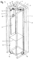
図1において、1は自己支持形シャフトを示し、エレベータケージ2およびカウンタウエイト3は移動可能である。エレベータケージ2およびカウンタウエイト3は駆動装置4によりケーブル5によって駆動され、エレベータシャフト内を案内部材6、7、8によって案内されるが、ある案内部材の一方の肢はエレベータケージ2の案内用とし、ある案内部材の他方の肢はカウンタウエイト3の案内用とする。キャリアヨーク9を第一の案内部材6と第二の案内部材7の上端に配置する。キャリアヨーク9はシャフト頭部に配置することもできる。ケーブル5はその一端をキャリアヨーク9の第一の固定点10に置き、他端を第三の案内部材8の第二の固定点11に置く。ケーブル5は、たとえば合成繊条または鋼製繊条により構成し、第一の固定点10から、カウンタウエイト3に配した第一のローラ12、次いでキャリアヨーク9に配置した第二のローラ13、次いで駆動装置4のドライブプーリ4.1、次いでキャリアヨーク9に配した第三のローラ14、次いでエレベータケージ2の底面に配置した第四のローラ15および第五のローラ16を経て第二の固定点11に及ぶ。
【0008】
図2および図3は、ピボットアーム17に常時接続し、かつ駆動装置4を配置したフレーム18を示す。ピボットアーム17は歯車19により駆動可能なピボット軸20に配置し、運転状態においてはスクリューカップリング等の固定部材21によりキャリアヨーク9に接続固定し、その場合には駆動装置4はシャフト頭部天板(図示せず)の下に、ドライブプーリ4.1を下向きにして水平位置にある。駆動装置4を旋回させるには、クランクピン22に取付け可能なクランク等により歯車19を駆動する。歯車は電動機によって駆動することもできる。歯車19により駆動するピボット軸20はピボットアーム17を軸支するので、フレーム18は駆動装置4とともにエレベータシャフト1内にある。破線で示す位置において、取付け、保守および修理作業を容易に行うことができ、しかもアクセスしやすい。ケーブルそらせ(cable deflection)23はピボット軸20にゆるく接続しておき、ドライブプーリ4.1に対するケーブルの過剰な斜め方向引っ張り(cable diagonal pull)を防止する。
【0009】
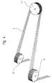
図4は、第二のローラ13からドライブプーリ4.1へ、そこから第三のローラ14へのケーブル5の案内を示す。この場合、ケーブルの面(cable plane)は水平から垂直状態に転じ、次いで再び水平状態に戻る。ローラ13、14およびドライブプーリ4.1の間隔が十分にあれば、ケーブルの斜め方向引っ張りは無視することができる。
【0010】
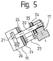
図5は、ベアリングブロック24および軸受25によりキャリアヨーク9に保持したピボット軸20を示す。ピボット軸20の一端はピボットアーム17に固定接続する。ウォーム26により駆動するウォームホイール27はピボット軸20の他端に配置する。ウォーム26はクランクピン22に常時接続しておく。旋回中の場合は、ピボット軸20にゆるく取付けたケーブルそらせ23が所定位置にとどまり、ドライブプーリ4.1に対するケーブルの過剰な斜め方向引っ張りを防止する。
【0011】
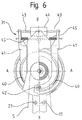
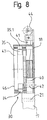
図6、図7および図8は、極数の多い同期電動機等の環状電動機30、制動装置31、タコメータ32およびフレーム18により構成する駆動装置を示し、図7から明らかなように、フレーム18が中央に中空の軸33を有し脚部をピボットアーム17に接続した錠前形式となっている。電動機30の環状固定子34はフレーム18の内壁に配置する。回転子35とドライブプーリ4.1とにより一つの回転装置を形成し、軸受36によって中空軸33で回転自在に支持する。軸受36はドライブプーリ4.1の力を受け、回転子35およびドライブプーリ4.1を案内する。タコメータ32は、中空軸33内のドライブプーリ側に配置し、プレート38により前記回転装置に接続する、中空軸33内に延在するシャフト37により駆動する。これらの重着物は回転子35の永久磁石35.1ともリテーナ39により挟持し、制動装置31の内部ブレーキシュー40の摩擦力を内側で受けることができる。内部ブレーキシュー40はブレーキシューレバー41に配置する。ブレーキシューレバー41の一端はフレーム18に固定接続したピン42に回動自在に取り付け、他端は電磁石44の各々の起動部材43に接続する。電磁石44は内部ブレーキシュー40に対するスプリング45により生ずるバネの力を緩和する。電磁石44およびスプリング45は左右対称に取り付けかつフレーム18に接続するので、ブレーキ装置31はその片側が故障の場合でも機能を維持することができる。
【0012】
錠前状の駆動装置の開口部はカバー46により閉じる。カバー46の下には駆動装置4の電子部品および調整機器用の空間47がある。
【図面の簡単な説明】
【図1】本発明によるエレベータ設備を備えた自己支持形シャフトの三次元図解である。
【図2】駆動装置を担持する回転メカニズムの側面図である。
【図3】図2の回転メカニズムの平面図である。
【図4】駆動装置の偏向ローラおよびドライブプーリ間のケーブルガイドを示す。
【図5】回転メカニズムの詳細を示す。
【図6】電動機、制動装置、ドライブプーリおよび発信器により構成する駆動装置の立面図である。
【図7】図6の駆動装置のA−A線断面図である。
【図8】図6の駆動装置のB−B線断面図である。
【符号の説明】
1、2 エレベータケージ
3 カウンタウエイト
4 駆動装置
4.1 ドライブプーリ
5 ケーブル
6 第一の案内部材
7 第二の案内部材
8 第三の案内部材
9 キャリアヨーク
10 第一の固定点
11 第二の固定点
12 第一のローラ
13 第二のローラ
14 第三のローラ
15 第四のローラ
16 第五のローラ[0001]
BACKGROUND OF THE INVENTION
The present invention relates to an elevator facility including a drive device disposed at an upper end of an elevator shaft, a drive pulley that drives an elevator cage guided by a guide member in the elevator shaft by a cable, and a counterweight.
[0002]
[Prior art]
From German utility model No. 8807219, an elevator installation is known in which a frame reaching the ceiling of the upper floor from the floor of the lower floor is used as a guide member for the elevator car. The frame has a platform under the ceiling of the upper floor, which is constituted by a cross beam for an electric motor, an elevator hoisting device and a switching device. The elevator car slides on rollers inside the angle block of the frame. The elevator cable is fed to a cable drum and wound and unwound in opposite directions by two deflecting rollers arranged at the height of the platform.
[0003]
[Problems to be solved by the invention]
The disadvantage of this known device is that the arrangement of the drive and cable guide is not suitable for an elevator installation with a counterweight. Furthermore, it is a drawback that it is difficult to access the drive device arranged under the ceiling together with the switching device, the electric motor and the hoisting device at the time of maintenance and inspection work.
[0004]
[Means for Solving the Problems]
The present invention provides a solution to this. The present invention avoids the disadvantages of the known devices and makes it possible to save the space by placing the drive device in the elevator shaft and to make the accessible elevator installation as indicated in the features of
[0005]
The advantages achieved by the present invention are, in essence, that the elevator installation does not require a machine room, thereby eliminating the expensive roof superstructure or cellar space normally required for the machine room. is there. Furthermore, it has the advantage that the shaft dimensions can be minimized, especially in the over-travel region. A further decisive advantage is that the elevator installation according to the invention only requires a self-supporting lift shaft, so that the elevator installation does not depend on the load carrying capacity of the building material and the shaft roof. That is.
[0006]
The invention will be described in more detail below with reference to the drawing, which is only an example.
[0007]
DETAILED DESCRIPTION OF THE INVENTION
In FIG. 1,
[0008]
2 and 3 show the
[0009]
FIG. 4 shows the guidance of the
[0010]
FIG. 5 shows the
[0011]
6, 7, and 8 show a driving device that includes an
[0012]
The opening of the lock-like drive device is closed by a
[Brief description of the drawings]
FIG. 1 is a three-dimensional illustration of a self-supporting shaft with an elevator installation according to the present invention.
FIG. 2 is a side view of a rotation mechanism carrying a driving device.
FIG. 3 is a plan view of the rotation mechanism of FIG. 2;
FIG. 4 shows a cable guide between a deflection roller and a drive pulley of a drive device.
FIG. 5 shows details of the rotation mechanism.
FIG. 6 is an elevational view of a driving device constituted by an electric motor, a braking device, a drive pulley, and a transmitter.
7 is a cross-sectional view taken along line AA of the drive device of FIG.
8 is a cross-sectional view of the driving device of FIG. 6 along the line BB.
[Explanation of symbols]
1, 2
Claims (21)
駆動装置(4)がエレベータシャフト(1)内において回転メカニズム(9、17、18、19、20)で旋回可能に配置されており、キャリアヨーク(9)に配置された駆動装置(4)がピボット軸(20)の周りを旋回可能であり、これにより、該駆動装置の駆動軸が鉛直方向を向くとともに、水平方向に旋回可能であり、
ピボットアーム(17)を伴うキャリアヨーク(9)を案内部材(6)またはエレベータシャフト(1)の上端に配置し、該ピボットアームの一端をキャリアヨーク(9)に移動可能に接続し、他端にフレーム(18)を駆動装置(4)とともに担持し、
歯車(19)により駆動可能で、かつピボットアーム(17)を駆動するピボット軸(20)をキャリアヨーク(9)に配置し、
運転状態においてはピボットアーム(17)をキャリアヨーク(9)に固定部材(21)により固定接続し、ドライブプーリ(4.1)を下向きにして駆動装置(4)を水平位置に置くことを特徴とする前記エレベータ設備。 The elevator car (2), which is disposed at the upper end of the elevator shaft (1) and is guided in the elevator shaft (1) by the guide member (6), is driven together with the counterweight (3) using the cable (5). An elevator installation comprising a drive device (4) having a drive pulley (4.1) for
The drive device (4) is disposed in the elevator shaft (1) so as to be rotatable by the rotation mechanism (9, 17, 18, 19, 20), and the drive device (4) disposed in the carrier yoke (9) is provided. Pivotable about a pivot shaft (20), whereby the drive shaft of the drive device is oriented vertically and pivotable horizontally,
A carrier yoke (9) with a pivot arm (17) is arranged at the upper end of the guide member (6) or the elevator shaft (1), and one end of the pivot arm is movably connected to the carrier yoke (9) and the other end Carrying the frame (18) together with the driving device (4),
A pivot shaft (20) that can be driven by the gear (19) and that drives the pivot arm (17) is arranged on the carrier yoke (9),
In the operating state, the pivot arm (17) is fixedly connected to the carrier yoke (9) by the fixing member (21), and the drive pulley (4.1) faces downward and the drive device (4) is placed in a horizontal position. the elevators equipment shall be the.
Applications Claiming Priority (2)
| Application Number | Priority Date | Filing Date | Title |
|---|---|---|---|
| CH96810762.3 | 1996-11-11 | ||
| EP96810762 | 1996-11-11 |
Publications (2)
| Publication Number | Publication Date |
|---|---|
| JPH10139321A JPH10139321A (en) | 1998-05-26 |
| JP4023883B2 true JP4023883B2 (en) | 2007-12-19 |
Family
ID=8225746
Family Applications (1)
| Application Number | Title | Priority Date | Filing Date |
|---|---|---|---|
| JP30885397A Expired - Fee Related JP4023883B2 (en) | 1996-11-11 | 1997-11-11 | Elevator equipment with drive device arranged in the elevator shaft |
Country Status (6)
| Country | Link |
|---|---|
| US (1) | US6006865A (en) |
| JP (1) | JP4023883B2 (en) |
| AT (2) | ATE273916T1 (en) |
| CA (1) | CA2220582A1 (en) |
| DE (2) | DE59709841D1 (en) |
| ES (2) | ES2227012T3 (en) |
Families Citing this family (71)
| Publication number | Priority date | Publication date | Assignee | Title |
|---|---|---|---|---|
| PL190277B1 (en) * | 1997-12-23 | 2005-11-30 | Inventio Ag | Rope-type hoisting winch with a driving disk |
| US6397974B1 (en) * | 1998-10-09 | 2002-06-04 | Otis Elevator Company | Traction elevator system using flexible, flat rope and a permanent magnet machine |
| FI109468B (en) * | 1998-11-05 | 2002-08-15 | Kone Corp | Pinion Elevator |
| JP2008273745A (en) * | 1999-01-08 | 2008-11-13 | Mitsubishi Electric Corp | Elevator system |
| JP4191331B2 (en) * | 1999-01-08 | 2008-12-03 | 三菱電機株式会社 | Elevator equipment |
| US6691833B1 (en) * | 1999-02-05 | 2004-02-17 | Inventio Ag | Elevator without a machine room |
| JP5056672B2 (en) * | 1999-06-03 | 2012-10-24 | 三菱電機株式会社 | Elevator equipment |
| JP2001039643A (en) * | 1999-08-03 | 2001-02-13 | Teijin Seiki Co Ltd | Elevator |
| DE50011320D1 (en) * | 1999-08-19 | 2006-02-23 | Inventio Ag | Elevator installation with a drive unit arranged in an elevator shaft |
| JP4493759B2 (en) * | 1999-09-13 | 2010-06-30 | 三菱電機株式会社 | Elevator equipment |
| JP2001080843A (en) * | 1999-09-14 | 2001-03-27 | Mitsubishi Electric Corp | Elevator equipment |
| FI106192B (en) * | 1999-09-16 | 2000-12-15 | Kone Corp | Lifting machinery for a lift |
| DE60041439D1 (en) * | 2000-02-22 | 2009-03-12 | Mitsubishi Electric Corp | LIFT DEVICE |
| JP3744764B2 (en) * | 2000-02-29 | 2006-02-15 | 東芝エレベータ株式会社 | Elevator apparatus and assembly method thereof |
| US6446763B1 (en) * | 2000-07-19 | 2002-09-10 | Otis Elevator Company | Integrated elevator installation hoist tool |
| US6619433B1 (en) * | 2000-07-24 | 2003-09-16 | Otis Elevator Company | Elevator system using minimal building space |
| WO2002016247A1 (en) | 2000-08-21 | 2002-02-28 | Mitsubishi Denki Kabushiki Kaisha | Elevator device |
| JP4727124B2 (en) * | 2000-08-28 | 2011-07-20 | 三菱電機株式会社 | Elevator equipment |
| CN1184131C (en) | 2000-08-29 | 2005-01-12 | 三菱电机株式会社 | Elevator device |
| JP2002080178A (en) * | 2000-09-04 | 2002-03-19 | Mitsubishi Electric Corp | Elevator device |
| DE60043516D1 (en) * | 2000-09-12 | 2010-01-21 | Mitsubishi Electric Corp | LIFT DEVICE |
| CN100340466C (en) * | 2000-09-20 | 2007-10-03 | 三菱电机株式会社 | Elevator device |
| JP4882195B2 (en) * | 2000-09-20 | 2012-02-22 | 三菱電機株式会社 | Elevator equipment |
| JP4661022B2 (en) * | 2000-09-20 | 2011-03-30 | 三菱電機株式会社 | Elevator system and inspection method thereof |
| EP1329412B1 (en) * | 2000-10-10 | 2009-12-09 | Mitsubishi Denki Kabushiki Kaisha | Elevator device |
| WO2002055424A1 (en) * | 2001-01-12 | 2002-07-18 | Mitsubishi Denki Kabushiki Kaisha | Elevator device |
| FI4928U1 (en) * | 2001-01-25 | 2001-05-23 | Kone Corp | Elevator |
| ZA200202936B (en) * | 2001-05-04 | 2002-11-22 | Inventio Ag | Permanent magnet electric machine. |
| WO2002098782A1 (en) | 2001-06-04 | 2002-12-12 | Mitsubishi Denki Kabushiki Kaisha | Elevator device |
| WO2002098781A1 (en) * | 2001-06-04 | 2002-12-12 | Mitsubishi Denki Kabushiki Kaisha | Elevator device |
| GB2395191B (en) * | 2001-11-05 | 2005-10-19 | Otis Elevator Co | Traction sheave elevators |
| GB2385867B (en) * | 2001-12-12 | 2005-06-29 | Mitsubishi Electric Corp | Elevator rope and elevator apparatus |
| EP1481935A4 (en) * | 2002-03-01 | 2010-09-01 | Mitsubishi Electric Corp | Elevaltor apparatus |
| KR100567364B1 (en) | 2002-04-26 | 2006-04-04 | 미쓰비시덴키 가부시키가이샤 | Elevator |
| KR20040010737A (en) * | 2002-04-30 | 2004-01-31 | 미쓰비시덴키 가부시키가이샤 | Elevator |
| JP4416381B2 (en) * | 2002-06-14 | 2010-02-17 | 東芝エレベータ株式会社 | Machine roomless elevator |
| WO2004022471A1 (en) * | 2002-09-03 | 2004-03-18 | Mitsubishi Denki Kabushiki Kaisha | Elevator device |
| CN100389056C (en) * | 2003-03-06 | 2008-05-21 | 因温特奥股份公司 | Elevator |
| JP4316507B2 (en) * | 2003-03-12 | 2009-08-19 | 三菱電機株式会社 | Elevator equipment |
| JPWO2004101419A1 (en) * | 2003-05-14 | 2006-07-13 | 三菱電機株式会社 | Elevator equipment |
| JP2004352377A (en) * | 2003-05-27 | 2004-12-16 | Otis Elevator Co | Elevator |
| EP1555236B1 (en) * | 2004-01-07 | 2018-09-26 | Inventio AG | Driving gear for elevator and methods for converting and for mounting the same |
| JP4895500B2 (en) * | 2004-01-07 | 2012-03-14 | インベンテイオ・アクテイエンゲゼルシヤフト | Elevator equipment drive device and method for replacing elevator equipment drive device |
| WO2005070806A1 (en) * | 2004-01-27 | 2005-08-04 | Mitsubishi Denki Kabushiki Kaisha | Drive unit for elevator apparatus, evator apparatus, installation method of elevator apparatus, and maintenance/inspection method of elevator apparatus |
| JP2005213004A (en) * | 2004-01-30 | 2005-08-11 | Mitsubishi Electric Corp | Under-car sheave type elevator device |
| EP1741660A4 (en) * | 2004-04-28 | 2009-12-30 | Mitsubishi Electric Corp | Elevator apparatus |
| US7624848B2 (en) * | 2004-05-07 | 2009-12-01 | Inventio Ag | Equipment for mounting an elevator drive |
| JP4525197B2 (en) * | 2004-06-17 | 2010-08-18 | 株式会社明電舎 | Elevator hoisting machine |
| JP4353872B2 (en) * | 2004-08-24 | 2009-10-28 | 東芝エレベータ株式会社 | Hoisting machine mounting apparatus and hoisting machine mounting method |
| US8701519B2 (en) * | 2006-06-28 | 2014-04-22 | Genmark Automation, Inc. | Robot with belt-drive system |
| US8220354B2 (en) * | 2006-06-28 | 2012-07-17 | Genmark Automation, Inc. | Belt-driven robot having extended Z-axis motion |
| FI118644B (en) * | 2006-11-17 | 2008-01-31 | Kone Corp | Elevator installing method for use during construction of tall building, involves dismounting machine room of elevator provided with room, and converting elevator into elevator without machine room by placing hoisting machine |
| JP5070912B2 (en) * | 2007-04-10 | 2012-11-14 | 株式会社日立製作所 | Elevator hoisting machine |
| EP2154099B1 (en) * | 2007-06-01 | 2014-12-24 | Mitsubishi Electric Corporation | Elevator device |
| JP2008303070A (en) * | 2008-08-22 | 2008-12-18 | Mitsubishi Electric Corp | Elevator apparatus |
| CN102232051B (en) * | 2008-12-05 | 2015-05-06 | 奥的斯电梯公司 | Elevator machine support |
| WO2010065040A1 (en) * | 2008-12-05 | 2010-06-10 | Otis Elevator Company | Elevator system and installation method |
| JP2010184791A (en) * | 2009-02-13 | 2010-08-26 | Toshiba Elevator Co Ltd | Elevator |
| FI125069B (en) * | 2009-10-28 | 2015-05-29 | Kone Corp | Fastening device for the lifting machinery of a lift and method for mounting the lifting machinery of a lift |
| DE102009053249A1 (en) * | 2009-11-06 | 2011-07-07 | Wobben, Aloys, 26607 | elevator |
| CA2775153A1 (en) * | 2009-12-09 | 2011-06-16 | Thyssenkrupp Elevator Capital Corporation | Elevator apparatus yielding no reverse rope bend |
| JP5516512B2 (en) * | 2011-06-10 | 2014-06-11 | 三菱電機株式会社 | Elevator equipment |
| EP2873637B1 (en) * | 2013-11-13 | 2016-02-03 | Kone Corporation | A hoisting machine, an elevator assembly, and method for improving vibration damping of a hoisting machine and in an elevator assembly |
| EP2985255B1 (en) * | 2014-08-11 | 2021-11-17 | KONE Corporation | Elevator |
| WO2016126933A1 (en) * | 2015-02-05 | 2016-08-11 | Otis Elevator Company | Vehicle and method for elevator system installation |
| KR20220111282A (en) * | 2019-12-19 | 2022-08-09 | 인벤티오 아게 | Drive systems for elevator installations, elevator installations, and methods for installing drives on supporting elements of elevator installations |
| CN113104696B (en) * | 2021-04-27 | 2023-03-24 | 赛奥智能电梯(苏州)有限公司 | Low-top machine room-free elevator driven by back-lying rows |
| CN117320992A (en) * | 2021-05-19 | 2023-12-29 | 因温特奥股份公司 | Drive system for an elevator installation, elevator installation and method for mounting a drive on a support element of an elevator installation |
| WO2024068846A1 (en) | 2022-09-30 | 2024-04-04 | Inventio Ag | Device for carrying a drive motor of an elevator system |
| WO2024133493A1 (en) | 2022-12-21 | 2024-06-27 | Inventio Ag | Device for carrying a drive motor of an elevator system |
| WO2024141295A1 (en) | 2022-12-31 | 2024-07-04 | Inventio Ag | Device for carrying a drive motor of an elevator system |
Family Cites Families (4)
| Publication number | Priority date | Publication date | Assignee | Title |
|---|---|---|---|---|
| US3101130A (en) * | 1960-10-12 | 1963-08-20 | Silopark S A | Elevator system in which drive mechanism is mounted upon the counterweight |
| CH666673A5 (en) * | 1985-05-10 | 1988-08-15 | Gebauer Ag | Drive for lifts and method of assembly. |
| DE8807219U1 (en) * | 1988-06-03 | 1988-08-18 | Remlinger, François, Boulay | Passenger elevator for two-storey residential buildings |
| FI96198C (en) * | 1994-11-03 | 1996-05-27 | Kone Oy | Pinion Elevator |
-
1997
- 1997-10-29 DE DE59709841T patent/DE59709841D1/en not_active Expired - Lifetime
- 1997-10-29 DE DE59711862T patent/DE59711862D1/en not_active Expired - Lifetime
- 1997-10-29 ES ES01110403T patent/ES2227012T3/en not_active Expired - Lifetime
- 1997-10-29 AT AT01110403T patent/ATE273916T1/en not_active IP Right Cessation
- 1997-10-29 ES ES97118762T patent/ES2197280T3/en not_active Expired - Lifetime
- 1997-10-29 AT AT97118762T patent/ATE237550T1/en not_active IP Right Cessation
- 1997-10-30 US US08/960,963 patent/US6006865A/en not_active Expired - Lifetime
- 1997-11-10 CA CA002220582A patent/CA2220582A1/en not_active Abandoned
- 1997-11-11 JP JP30885397A patent/JP4023883B2/en not_active Expired - Fee Related
Also Published As
| Publication number | Publication date |
|---|---|
| JPH10139321A (en) | 1998-05-26 |
| US6006865A (en) | 1999-12-28 |
| DE59711862D1 (en) | 2004-09-23 |
| ES2197280T3 (en) | 2004-01-01 |
| ATE237550T1 (en) | 2003-05-15 |
| ATE273916T1 (en) | 2004-09-15 |
| DE59709841D1 (en) | 2003-05-22 |
| CA2220582A1 (en) | 1998-05-11 |
| ES2227012T3 (en) | 2005-04-01 |
Similar Documents
| Publication | Publication Date | Title |
|---|---|---|
| JP4023883B2 (en) | Elevator equipment with drive device arranged in the elevator shaft | |
| EP0841283B1 (en) | Elevator system with the drive machinery unit arranged inside the hoistway | |
| US6488124B1 (en) | Elevator | |
| JP2593288B2 (en) | Traction sheave elevator | |
| JP3571746B2 (en) | Elevator motor placed in counterweight | |
| EP0710618B2 (en) | Traction sheave elevator | |
| FI93632C (en) | Sub-lift type drive lift | |
| US7025177B1 (en) | Elevator system without machine | |
| KR100208425B1 (en) | Elevator equipment | |
| EP1333000A1 (en) | A machine-roomless traction sheave elevator | |
| JP2001518434A (en) | Cable / rope elevator | |
| KR100430113B1 (en) | Elevator | |
| US6619433B1 (en) | Elevator system using minimal building space | |
| JP4255525B2 (en) | Elevator | |
| JP4145977B2 (en) | elevator | |
| KR101998869B1 (en) | Heavy Duty Machine Roomless Elevator | |
| JPH0631145B2 (en) | Elevator device | |
| US7299896B1 (en) | Elevator system having drive motor located adjacent to hoistway door | |
| JP4129901B2 (en) | Elevator equipment | |
| KR970009387B1 (en) | Brake of an elevator using linear motor | |
| JPH04213581A (en) | Installation method for linear motor type elevator | |
| CN211971435U (en) | Elevator accessory | |
| KR100688362B1 (en) | Driving system of elevator | |
| KR20040013117A (en) | Elevator winch and elevator device | |
| JP2000007253A (en) | Small sized elevator device |
Legal Events
| Date | Code | Title | Description |
|---|---|---|---|
| A621 | Written request for application examination |
Free format text: JAPANESE INTERMEDIATE CODE: A621 Effective date: 20040827 |
|
| A521 | Request for written amendment filed |
Free format text: JAPANESE INTERMEDIATE CODE: A523 Effective date: 20040928 |
|
| A131 | Notification of reasons for refusal |
Free format text: JAPANESE INTERMEDIATE CODE: A131 Effective date: 20061107 |
|
| A521 | Request for written amendment filed |
Free format text: JAPANESE INTERMEDIATE CODE: A523 Effective date: 20070206 |
|
| A02 | Decision of refusal |
Free format text: JAPANESE INTERMEDIATE CODE: A02 Effective date: 20070403 |
|
| A521 | Request for written amendment filed |
Free format text: JAPANESE INTERMEDIATE CODE: A523 Effective date: 20070629 |
|
| A911 | Transfer to examiner for re-examination before appeal (zenchi) |
Free format text: JAPANESE INTERMEDIATE CODE: A911 Effective date: 20070806 |
|
| TRDD | Decision of grant or rejection written | ||
| A01 | Written decision to grant a patent or to grant a registration (utility model) |
Free format text: JAPANESE INTERMEDIATE CODE: A01 Effective date: 20070911 |
|
| A61 | First payment of annual fees (during grant procedure) |
Free format text: JAPANESE INTERMEDIATE CODE: A61 Effective date: 20071002 |
|
| R150 | Certificate of patent or registration of utility model |
Free format text: JAPANESE INTERMEDIATE CODE: R150 |
|
| FPAY | Renewal fee payment (event date is renewal date of database) |
Free format text: PAYMENT UNTIL: 20101012 Year of fee payment: 3 |
|
| FPAY | Renewal fee payment (event date is renewal date of database) |
Free format text: PAYMENT UNTIL: 20101012 Year of fee payment: 3 |
|
| FPAY | Renewal fee payment (event date is renewal date of database) |
Free format text: PAYMENT UNTIL: 20111012 Year of fee payment: 4 |
|
| FPAY | Renewal fee payment (event date is renewal date of database) |
Free format text: PAYMENT UNTIL: 20111012 Year of fee payment: 4 |
|
| FPAY | Renewal fee payment (event date is renewal date of database) |
Free format text: PAYMENT UNTIL: 20121012 Year of fee payment: 5 |
|
| FPAY | Renewal fee payment (event date is renewal date of database) |
Free format text: PAYMENT UNTIL: 20121012 Year of fee payment: 5 |
|
| FPAY | Renewal fee payment (event date is renewal date of database) |
Free format text: PAYMENT UNTIL: 20131012 Year of fee payment: 6 |
|
| R250 | Receipt of annual fees |
Free format text: JAPANESE INTERMEDIATE CODE: R250 |
|
| R250 | Receipt of annual fees |
Free format text: JAPANESE INTERMEDIATE CODE: R250 |
|
| LAPS | Cancellation because of no payment of annual fees |