JP4022068B2 - Endoscope system - Google Patents
Endoscope system Download PDFInfo
- Publication number
- JP4022068B2 JP4022068B2 JP2001401834A JP2001401834A JP4022068B2 JP 4022068 B2 JP4022068 B2 JP 4022068B2 JP 2001401834 A JP2001401834 A JP 2001401834A JP 2001401834 A JP2001401834 A JP 2001401834A JP 4022068 B2 JP4022068 B2 JP 4022068B2
- Authority
- JP
- Japan
- Prior art keywords
- image
- endoscope
- tomographic image
- optical
- tomographic
- Prior art date
- Legal status (The legal status is an assumption and is not a legal conclusion. Google has not performed a legal analysis and makes no representation as to the accuracy of the status listed.)
- Expired - Fee Related
Links
Images


Description
【0001】
【発明の属する技術分野】
本発明は、体腔内の被写体の光学像を得るための内視鏡を具備した内視鏡システムに関する。
【0002】
【従来の技術】
近年、微細な患部の手術であるマイクロサージャリーの発達及び普及に伴い、眼科、脳神経外科、耳鼻科等は勿論のこと、さまざまな分野で手術用顕微鏡下で行うマイクロサージャリーが盛んになってきている。これに伴い、当然のことながら、手術用顕微鏡も術者の手術手技等に応じてさまざまな要求がなされ、改良が加えられている。
【0003】
さらに、最近の手術は、手術後の患者の早期社会復帰を考慮して、より低侵襲な手術へと変化してきており、より細孔内での術部等の観察が望まれている。さらに、体腔内深部の観察においては、顕微鏡観察では影になって観察できない部位についても手術における正確性をより向上させるために観察可能にすることが望まれている。
【0004】
このような問題点を改善する手段として、事前にX線CT(コンピュータ断層撮影装置)、MRI(磁気共鳴断層撮影装置)等の画像診断より得られた断層画像データをモニタに映し出し、その画像を基に、目的の治療部位や手術器具が何処にあるか、どのように移動しているかを表示して手術を進める方法があった。
【0005】
さらに、近年では、細孔内部に対して内視鏡を併用して手術を行う方法も取られ、特開平5−305073号公報に開示されるように内視鏡や処置器具の位置を術前診断画像に投影して手術を写す方法があった。
【0006】
また、内視鏡を使用する場合、特開昭61−244323号公報、特公平7−62737号公報、特公平8−22272号公報、特開平8−238216号公報、及び特公平2543855号公報で開示されているように、内視鏡固有の情報を内視鏡自体が持ち、それに基づいて内視鏡の画像を補正し、適切な内視鏡画像を提供する方法があった。
【0007】
【発明が解決しようとする課題】
前記した従来の技術では、細孔内観察用の補助光学系を用いて、術者が顕微鏡観察では死角になる観察できない部位、例えば動脈瘤の裏側、腫瘍剥離後の神経または周囲組織等の観察を行うときは、内視鏡などの補助光学系によって撮像された映像を視野内に表示して行うが、その場合、内視鏡によって撮像された像がどの部位にあたるかを把握する必要がある。
【0008】
そのために、この内視鏡の映像にMRIやX線CTなどの術前診断画像を表示させる場合があるが、内視鏡の光学系による像面の歪みによって実際の観察組織と術前診断画像との位置の対応がずれる可能性があった。これにより、目的の腫瘍や血管の位置を正確に把握できず処置が難しくなることがあった。この問題に対して従来技術で挙げた内視鏡像の補正手段があるが、X線CTなどの平面画像との位置合わせを行う場合、X線CTなどの平面画像に対し、内視鏡画像は立体面を撮像した画像であり、その歪みを除去するのは容易ではなく正確さに欠けていた。
【0009】
本発明は、上記事情を鑑みてなされたものであり、内視鏡の光学系で得られる観察画像と、この観察画像に対応した断層画像信号とを正確に位置合わせすることができる内視鏡システムを提供することを目的とする。
【0010】
【課題を解決するための手段】
前記目的を達成するため、本発明の内視鏡システムは、体腔内の被写体の光学像を得る光学系と、焦点面に応じた像面湾曲情報が像面湾曲情報として記憶されたメモリと、を具備する内視鏡と、前記光学系によって得られた前記光学像を撮像する撮像部と、前記内視鏡の先端の位置、及び、前記光学系の光軸方向に存在する前記被写体の位置を検出する位置検出部と、前記位置検出部の検出結果に基づき、前記被写体の位置における前記被写体の断層像を断層画像信号として取得する断層像取得部と、前記メモリに記憶された前記像面湾曲情報に基づき、前記断層像取得部が取得した前記断層像に対し、前記光学像の湾曲状態と同等の湾曲状態を与えるための歪み処理を施す画像変形部と、前記光学像、及び、前記歪み処理が施された断層像を合成して出力する画像合成部と、を具備することを特徴とする。
【0011】
【発明の実施の形態】
以下、本発明の実施の形態を図面を参照して説明する。
(第1の実施の形態)
図1及び図2は本発明の第1の実施の形態に係り、図1は内視鏡装置の全体構成を示す説明図、図2は内視鏡とカメラヘッドの接続部を示す断面図である。
【0012】
(構成)
まず、図1を用いて内視鏡装置の全体構成を説明する。
図1に示すように、内視鏡装置1は、内視鏡テレビ観察装置に適用したものである。
【0013】
この内視鏡装置1は、内視鏡11と、テレビカメラヘッド12と、カメラコントロールユニット14と、ナビゲーション装置17と、断層画像信号入力手段18と、マーカ19aと、デジタイザ19bと、ミキサ21と、モニタ23とから構成されている。
【0014】
前記内視鏡11は、細長な挿入部31と、この挿入部31の後端に連設された接眼部32とを有して構成されている。
【0015】
被写体の光学像は、挿入部31の先端部に設けられた図示しない対物レンズによって内視鏡11の図示しないリレー光学系に結像され、この結像された像はそのリレー光学系により接眼部32側に伝送される。そして、接眼部32の図示しない接眼レンズを介して肉眼で観察出来るようになっている。
【0016】
前記接眼部32には、前記テレビカメラヘッド12が着脱自在で装着される。テレビカメラヘッド12は、固体操像素子としての、図2に示すCCD39を内蔵している。このテレビカメラヘッド12は、CCD39で内視鏡像を光電変換により電気信号に変換する。変換された電気信号はテレビカメラヘッド12から延出されたケーブル13によってカメラコントロールユニット14に伝送される。カメラコントロールユニット14はケーブル13から伝送される電気信号を映像信号に変換して映像ケーブル15に出力する。
【0017】
カメラコントロールユニット14は映像ケーブル15によってミキサ21に接続されている。
【0018】
また、テレビカメラヘッド12はケーブル16によってナビゲーション装置17に接続されている。
【0019】
テレビカメラヘッド12にはマーカ19aが取り付けらている。デジタイザ19bはマーカ19aの位置の検出を行い、この検出結果のデータ信号をナビゲーション装置17に供給する。また、ナビゲーション装置17にはMRIやCTによって得られた断層画像信号であるところの術前診断画像a1が断層画像信号入力手段18によって供給されるようになっている。ナビゲーション装置17の出力側はケーブル20を介して前記ミキサ21に接続されている。
【0020】
前記ミキサ21の出力側は映像ケーブル22を介してモニタ23に接続されている。
【0021】
ここで、断層画像信号入力手段18には、MRIやCTと電気的に接続するインターフェイス、MRIやCTによって得られた術前診断画像a1を記録した記録媒体の読み出しを行う記録媒体読み出し手段等を用いている。
【0022】
次に、図2を用いて内視鏡11とテレビカメラヘッド12の接続部を詳細に説明する。
【0023】
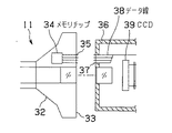
図2に示すように、内視鏡11の接眼部32のアイピース33内部にはメモリチップ34が配置されている。前記メモリチップ34の制御線及びデータ線は端子35によってアイピース33の外部に接続されている。
【0024】
一方、テレビカメラヘッド12の接続部36には、前記端子35に着脱可能な端子37が設けられている。端子37はデータ線38に接続されされている。データ線38は、図1に示した前記ケーブル16としてテレビカメラヘッド12の外部に引き出されている。また、テレビカメラヘッド12の接続部36には光学像を光電変換するCCD39が配置されている。CCD39の出力は図1に示したケーブル13によってカメラコントロールユニット14に供給される。
【0025】
このような構成により、内視鏡装置1は、内視鏡11の挿入部31が体腔内に挿入されるとともに挿入部31の所定の光学系を介して前記体腔内を撮像するようになっている。
【0026】
メモリチップ34、端子35,37及びデータ線38は、前記内視鏡装置1の内視鏡11の前記光学系に関する光学情報を入力する光学情報入力手段となっている。
【0027】
断層画像信号入力手段18は、前記体腔内の断層画像を表示可能な所定の医療観察装置で得られた断層画像信号(術前診断画像a1)を入力するようになっている。
【0028】
ナビゲーション装置17は、前記光学情報入力手段からの前記光学情報に基づいて前記断層画像信号入力手段18からの前記断層画像信号を処理し、前記内視鏡装置1の前記光学系で得られる観察画像に対応した断層画像信号を得る断層画像信号処理手段となっている。
【0029】
(作用)
次に、上記構成よりなる本実施の形態の作用について説明する。
図1において、内視鏡11によって捕らえられた図示しない光学像は、図2のCCD39によって光電変換され、ケーブル13を介してカメラコントロールユニット14によって映像信号に変換され、映像ケーブル15によってミキサ21に入力される。
【0030】
次に、図2において、メモリチップ32には、内視鏡11あるいは図示しないほかの種類の内視鏡の、図示しない焦点面および焦点面より遠点の少なくとも2つの光学収差による像面湾曲情報が記憶されている。前記像面湾曲情報は内視鏡の種類によって異なった値を持つ。メモリチップ32の像面湾曲情報は、端子35に出力され、端子37、データ線38及び図1のケーブル16によってナビゲーション装置17に送られる。
【0031】
ナビゲーション装置17では、マーカ19aおよびデジタイザ19bにより、内視鏡11の先端、および先端から光軸方向に一定距離の術部に対する位置を検知する。
【0032】
次に、ナビゲーション装置17では、前記位置の検知結果に基づいて、MRIやCTによって得られた術前診断画像a1を、カメラコントロールユニット14で得られた内視鏡画像に位置関係が一致するように拡大あるいは縮小および回転処理する。
【0033】
さらに、ナビゲーション装置17は、メモリチップ32からの像面湾曲情報に基づいて、術前診断画像a1を写像変換による変形処理を行ってケーブル20によってミキサ21に入力する。
【0034】
ミキサ21では、ケーブル20からの映像とケーブル15からの映像を合成処理し、モニタ23に出力する。
【0035】
図3及び図4はナビゲーション装置17の内部での処理を示す説明図であり、図3は内視鏡11として第1の種類となる内視鏡Aを用いた場合を示し、図4は内視鏡11として第2の種類となる内視鏡Bの場合を示している。
【0036】
図3において、内視鏡A像41は第1の種類となる内視鏡Aの像面湾曲を示すものである。
【0037】
前記術前診断画像a1として供給されるナビゲーションa画像42は、歪みのない画像である。前記ナビゲーション装置17内部の画像変形手段43は、ナビゲーションa画像42に対して、内視鏡Aの前記メモリチップ34に記憶された像面湾曲情報であるスコープ湾曲パターンデータb1により、内視鏡A像41と同等のパターンの画像変形を加えてナビゲーションa’画像45として出力する。
【0038】
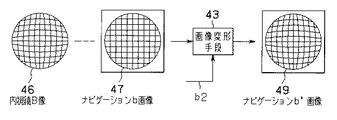
一方、図4において、内視鏡A像41と異なる内視鏡B像46は第2の種類となる内視鏡Bの像面湾曲を示すものである。
【0039】
内視鏡A像41と異なる内視鏡B像46は図示しない内視鏡Bの像面湾曲を示すものである。前記術前診断画像a1として供給される腫瘍の位置・形状等を示すナビゲーションb画像47は歪みのない画像である。前記画像変形手段43は、ナビゲーションb画像47に対して、内視鏡Bの前記メモリチップ34に記憶された像面湾曲情報である内視鏡湾曲パターンデータb2により、内視鏡B像46と同等のパターンの画像変形を加えてナビゲーションb’画像49として出力する。
【0040】
(効果)
第1の本実施の形態によれば、内視鏡装置1の光学系で得られる観察画像であるところの内視鏡画像に、術前診断画像である光軸方向に垂直な断層画像を投影する場合、断層画像に対して内視鏡画像と同様の画像変形を加えるので、内視鏡装置の光学系で得られる観察画像と、この観察画像に対応した断層画像とを正確に位置合わせして精度良く重畳でき、さらに内視鏡を付け替えても内視鏡の種類に応じて補正された術前診断画像が重畳される。これにより、内視鏡を用いて手術を行う場合において術者に必要な術前診断情報を正確に提供することができ、手術の作業効率を向上できる。
【0041】
(第2の実施の形態)
図5及び図6は本発明の第2の実施の形態に係り、図5は内視鏡装置の全体構成を示す説明図、図6は内視鏡とカメラヘッド接続部を示す断面図である。図5及び図6の説明においては、図1及び図2に示した実施の形態と同様の構成要素に同じ符号を付して説明を省略している。
【0042】
(構成)
図5に示すように、内視鏡装置2の前記内視鏡11で得られた光学像は、ズーム付きテレビカメラヘッド50によって光電変換され電気信号に変換される。このテレビカメラヘッド50にはズームリング51が設けられている。
【0043】
テレビカメラヘッド50により変換された信号は、ケーブル13を介してカメラコントロールユニット14によって映像信号に変換され、映像ケーブル15によってミキサ21に供給される。
【0044】
一方、テレビカメラヘッド50は、ケーブル56によってナビゲーション装置57に接続されている。ナビゲーション装置57は、ケーブル20を介して前記ミキサ21に接続されている。前記ミキサ21の出力はモニタ23に供給される。
【0045】
次に、図6を用いてテレビカメラヘッド50の接続部を詳細に説明する。
図6に示すように、テレビカメラヘッド50に接続される前記内視鏡11は第1の実施の形態と同じ構造である。一方カメラヘッド接続部66にはスコープ接続端子67がある。スコープ接続端子67は、データ線68に接続されている。データ線68はカメラヘッド50の外部に引き出されている。
【0046】
また、カメラヘッド接続部66には光学像を光電変換するCCD69が配置される。CCD69の出力端子は図5に示すカメラコントロールユニット14に接続されている。CCD69の前方には、内視鏡11の光学像の変倍を行うズーム光学系70が設けられている。ズーム光学系70は、ズームリング51の回転により各レンズの位置が前後することで、光学像の変倍を行う。
【0047】
ズームリング51の内部構造71の近傍には、ズームリング51の回転角の検出を行う回転角検出器72が配置されている。回転角検出器72の出力はズーム倍率信号c1として図5のケーブル56によってナビゲーション装置57に出力されている。
【0048】
(作用)
次に、上記構成よりなる第2の実施の形態の作用について説明する。
図5において 内視鏡11によって捕らえられた図示しない光学像は図6のズーム光学系70を介してCCD69によって光電変換される。CCD69によって光電変換された信号は、カメラコントロールユニット14によって映像信号に変換され、ミキサ21に入力される。
【0049】
一方、図6に示すように、メモリチップ32からの前記像面湾曲情報は図6の端子67及びデータ線68を介して内視鏡像湾曲パターンデータ信号b1としてナビゲーション装置57に送られる。
【0050】
ナビゲーション装置57では、MRIやCTによって得られた術前診断画像a1を、マーカ19aとデジタイザ19bによる内視鏡11の先端および、先端から一定距離の位置情報、さらに前記像面湾曲情報およびズーム倍率信号c1に基づいて変形処理してケーブル20によってミキサ21に入力する。ミキサ21では2つの映像を合成処理し、モニタ23に出力する。
【0051】
図7及び図8はナビゲーション装置57の内部での処理を示す説明図であり、図7はズームリング51を高倍率側にセットした場合を示し、図4はズームリング51を低倍率側にセットした場合を示している。
【0052】
図7に示すように、ズームリング51を高倍率側にセットした場合はCCD69には内視鏡像(高倍率)81が撮像される。
【0053】
内視鏡像(高倍率)81はテレビカメラヘッド50が高倍率で撮像した場合の内視鏡11の光学像の像面湾曲を示すものである。
【0054】
前記術前診断画像であるナビゲーション画像T82は歪みのない画像であるが、前記ナビゲーション装置57の内部の画像変形手段83は、ナビゲーション画像T82に対して、前記メモリチップ34に記憶された像面湾曲情報である内視鏡湾曲パターンデータb1とズーム倍率信号c1により、内視鏡像(高倍率)81と同等のパターンの画像変形を加えてナビゲーション画像T’85として出力する。
【0055】
一方、ズームリング51を低倍率側にセットした場合は、CCD69には図7に示すように、内視鏡像(低倍率)86が撮像される。
【0056】
内視鏡像(低倍率)86はテレビカメラヘッド50が低倍率で撮像した場合の内視鏡11の光学像の像面湾曲を示すものである。
【0057】
前記術前診断画像であるナビゲーション画像W87は歪みのない画像であるが、前記ナビゲーション装置内部の画像変形手段83は、ナビゲーション画像W87に対して、前記内視鏡湾曲パターンデータb1とズーム倍率信号c1により、内視鏡像(低倍率)86と同等のパターンの画像変形を加えてナビゲーション画像W’89として出力する。
【0058】
(効果)
第2の実施の形態によれば、第1の本実施の形態と同様に内視鏡画像に術前診断画像である深さ方向に垂直な断層画像を投影する場合、内視鏡画像に対して精度良く重畳できることに加えて、さらにズーム倍率を変えても補正された断層画像を精度良く重畳できる。
【0059】
(第3の実施の形態)
ところで、内視鏡により処置を行う場合、表示させている診断画像が内視鏡の先端からどれだけの距離にあるか、または組織表面からどれだけの深さの像であるかを判断しながら進めなければならない。従来は頭骸の座標に対して術前診断画像を表示するため、内視鏡像に対しての診断画像の位置関係の把握が難しかった。
【0060】
第3の実施の形態は、このような事情に鑑みて成されたものであり、術中簡便な操作により目的の術前診断画像を表示することができる内視鏡装置を提供することを目的にしている。
【0061】
図9乃至図11は本発明の第3の実施の形態に係り、図9は内視鏡装置の全体構成を示す説明図、図10は内視鏡の先端部を示す断面図、図11はモニタに表示される画像を示す平面図である。
【0062】
(構成)
図9に示すように、内視鏡装置3は、内視鏡91と、テレビカメラヘッド92と、カメラコントロールユニット94と、ナビゲーション装置97と、断層画像信号入力手段98と、マーカ99aと、デジタイザ99bと、ミキサ101と、モニタ103と、距離設定手段104とから構成されている。
【0063】
カメラコントロールユニット94、断層画像信号入力手段98、マーカ99a、デジタイザ99b、ミキサ101、モニタ103は、図1の第1の実施の形態と同様の構成になっている。
【0064】
内視鏡91はテレビカメラヘッド92に接続され光学像を光電変換する。テレビカメラヘッド92はカメラコントロールユニット94に接続される。カメラコントロールユニット94の出力はミキサ101に接続されている。また、テレビカメラヘッド92にはマーカ99aが取り付けられている。
【0065】
一方、図10に示すように、内視鏡91の先端部121は、観察光学系122と照明光学系123を有している。また、先端部121の径両端には超音波振動子124および超音波受信子125が配置されている。
【0066】
超音波受信子125の出力は図9に示すテレビカメラヘッド92を介して超音波測距手段105に接続される。
【0067】
図9に示ように、超音波測距手段105は、前記超音波受信子125の出力に基づいて距離データを作成してナビゲーション装置97に入力する。
【0068】
ナビゲーション装置97は、ミキサ101、デジタイザ99b及び距離設定手段104に接続されている。ミキサ101の出力側はモニタ103に接続される。モニタ103には図11に示すモニタ画面141が表示される。
【0069】
図11に示すように、モニタ画面141は、内視鏡画像142およびその画像中心143、断層画像144、内視鏡先端からの距離145、そして、内視鏡先端から断層画像までの距離146で構成される。
【0070】
なお、断層画像144は内視鏡画像142に重畳されても良い。
【0071】
(作用)
次に、第3の形態の作用について説明する。
【0072】
図10に示すように、内視鏡91は、先端部121の照明光学系123によって図示しない光源装置による照明光を伝送し、組織129を照明する。組織129の画像は観察光学系122によって伝送されテレビカメラヘッド92内のCCDおよびカメラコントロールユニット94によって映像信号に変換される。
【0073】
内視鏡91およびテレビカメラヘッド92によって撮像された内視鏡像、およびナビゲーション装置97からの術前診断画像a1による断層画像は、ミキサ101によって合成されモニタ103に表示される。
【0074】
尚、図10に示す画像中心128は図11に示す内視鏡像142が画像中心143の位置に表示される。
【0075】
一方、図10に示すように、超音波振動子124からの超音波信号の出力波126は、組織129により反射され、この反射信号の反射波127は超音波受信子125によって電気信号に変換され、その反射波形より図9に示す超音波測距手段105は先端部121から組織129までの距離130を計算する。超音波測距手段105による距離情報はナビゲーション装置97に入力され、断層画像入力手段98からの術前診断画像a1による断層画像144と共に、先端からの距離の表示145としてモニタ画面141に表示される。
【0076】
一方、図9に示す距離設定手段104によって図10に示す先端部121からの距離131が設定される。ナビゲーション装置97は、先端部121からの距離131で、該距離131の奥行き方向に垂直な組織129内の断層面132を設定し、この断層面132にある断層画像を断層画像入力手段98からの術前診断画像a1から選択して、図11に示すモニタ画面141に断層画像144として表示する。また、距離設定手段104によって設定された距離131はモニタ画面141に距離情報(断層画像からの距離の表示146)として表示する。断層画像144は内視鏡11が移動された場合も、内視鏡11の移動に合わせて設定された距離131を保ちながら更新される。
【0077】
(効果)
第3の実施の形態によれば、モニタ画面141に内視鏡画像142とともに術前診断画像である組織の深さ方向に垂直な断層画像144を表示する場合、その表示距離を任意の深さに設定ができ、内視鏡画像142に対して見たい深さの断層画像144の選択が可能となるとともに、先端部121から組織129までの距離をリアルタイムに表示することにより断層画像144の組織表面からの深さを知ることができ、断層画像を設定する内視鏡からの距離を判断しやすくなる。
【0078】
また、内視鏡画像142に断層画像144を重ねて投影する場合についても同様の効果が得られる。
【0079】
(第4の実施の形態)
図12及び図13は本発明の第4の実施の形態に係り、図12は内視鏡の先端部を示す断面図、図13はモニタに表示される画像を示す平面図である。第4の実施の形態の全体構成については図9を代用して説明する。
【0080】
(構成)
第4の実施の形態は、図12に示す組織129からの深さを図9に示す距離設定手段104により設定し、この深さにある断層画像を図9に示す断層画像入力手段98からの術前診断画像a1から選択して、図13に示すモニタ画面161に表示する。
【0081】
モニタ画面161は、内視鏡画像162、断層画像163、先端からの距離165、表面からの深さ166が表示される。
【0082】
(作用)
まず、術者は、図9に示す距離設定手段104によって図12に示す組織129からの深さ(図13に示す深さ166の数値)を設定する。これにより、ナビゲーション装置97は、断層画像を表示する内視鏡91の先端部121からの距離131を、先端部121からの距離130と組織129の表面からの深さ和として計算し、計算した距離にある断層画像を断層画像入力手段98からの術前診断画像a1から選択して、図13に示すモニタ画面161に断層画像163として表示する。これにより、内視鏡の先端からの距離130が変化しても、常に一定の深さの断層画像▲1▼151、断層画像▲2▼152、断層画像▲3▼153、断層画像▲4▼154が得られる。
【0083】
(効果)
このような第4の実施の形態によれば、モニタ画面161に内視鏡画像162とともに術前診断画像である組織の深さ方向に垂直な断層画像を表示する場合において、内視鏡91の先端部121が変化した場合にも組織129の表面からの任意の深さの断層画像を常に表示することが出来る。
【0084】
また、内視鏡画像162に断層画像164を重ねて投影する場合についても同様の効果が得られる。
【0085】
[付記]
以上詳述したような本発明の上記実施の形態によれば、以下の如き構成を得ることができる。
【0086】
(付記項1) 体腔内に挿入されるとともに所定の光学系を介して前記体腔内を撮像する内視鏡装置において、
前記内視鏡装置の前記光学系に関する光学情報を入力する光学情報入力手段と、
前記体腔内の断層画像を表示可能な所定の医療観察装置で得られた断層画像信号を入力する断層画像信号入力手段と、
前記光学情報入力手段からの前記光学情報に基づいて前記断層画像信号入力手段からの前記断層画像信号を処理し、前記内視鏡装置の前記光学系で得られる観察画像に対応した断層画像信号を得る断層画像信号処理手段と、
を具備したことを特徴とする内視鏡装置。
【0087】
(付記項2) 内部に固有の情報を保持する手段を具備する内視鏡において、
前記固有情報が前記内視鏡の光学系の像面湾曲情報であり、
前記固有情報により処理を行う術前診断画像表示装置と、
前記内視鏡の画像内に術前診断画像を表示する手段と、
を具備することを特徴とする内視鏡装置。
【0088】
(付記項3) 前記光学系の倍率を変更する手段と、
倍率変更情報を出力する手段と、
を具備し、前記術前診断画像表示装置が前記倍率変更情報と前記固有情報により処理を行うことを特徴とする付記項2に記載の内視鏡装置。
【0089】
(付記項4) 前記内視鏡の先端からの距離を指定する距離設定手段と、
前記内視鏡の組織からの距離測定手段と、
前記距離設定手段により指定距離の術前診断画像を表示する術前診断画像表示装置と、
を具備することを特徴とする付記項3に記載の内視鏡装置。
【0090】
(付記項5) 前記距離測定手段が超音波振動子および受信子であることを特徴とする付記項4に記載の内視鏡装置。
【0091】
(付記項6) 前記距離測定手段が可干渉光を用いることを特徴とする付記項4に記載の内視鏡装置。
【0092】
(付記項7) 前記術前診断画像表示装置が前記像面湾曲情報により、湾曲画像を平面に戻す処理を行うことを特徴とする付記項3に記載の内視鏡装置。
【0093】
(付記項8) 前記像面湾曲情報が、焦点位置、およびその前後の情報であることを特徴とする付記項3に記載の内視鏡装置。
【0094】
(付記項9) 前記術前診断画像表示装置が、組織の深さを指定する手段と、前記組織の深さと前記距離測定手段による結果の和によって前記術前診断画像を表示することを特徴とする付記項4に記載の内視鏡装置。
【0095】
(付記項10) 前記距離手段による距離情報を表示する表示手段を有することを特徴とする付記項4に記載の内視鏡装置。
【0096】
【発明の効果】
以上述べた様に、本発明の内視鏡システムによれば、内視鏡の光学系で得られる観察画像と、この観察画像に対応した断層画像信号とを正確に位置合わせできるので、内視鏡を用いて手術を行う場合において術者に必要な術前診断情報を正確に提供でき、手術の作業効率を向上できる。
【図面の簡単な説明】
【図1】本発明の第1の実施の形態に係る内視鏡装置の全体構成を示す説明図。
【図2】本発明の第1の実施の形態に係る内視鏡とカメラヘッドの接続部を示す断面図。
【図3】本発明の第1の実施の形態に係るナビゲーション装置の内部での処理を示す第1の説明図。
【図4】本発明の第1の実施の形態に係るナビゲーション装置の内部での処理を示す第2の説明図。
【図5】本発明の第2の実施の形態に係る内視鏡装置の全体構成を示す説明図。
【図6】本発明の第2の実施の形態に係る内視鏡とカメラヘッドの接続部を示す断面図。
【図7】本発明の第2の実施の形態に係るナビゲーション装置の内部での処理を示す第1の説明図。
【図8】本発明の第2の実施の形態に係るナビゲーション装置の内部での処理を示す第2の説明図。
【図9】本発明の第3の実施の形態に係る内視鏡装置の全体構成を示す説明図。
【図10】本発明の第3の実施の形態に係る内視鏡の先端部を示す断面図。
【図11】本発明の第3の実施の形態に係るモニタに表示される画像を示す平面図。
【図12】本発明の第4の実施の形態に係る内視鏡の先端部を示す断面図。
【図13】本発明の第4の実施の形態に係るモニタに表示される画像を示す平面図。
【符号の説明】
1 …内視鏡装置
11 …内視鏡
12 …テレビカメラヘッド
14 …カメラコントロールユニット
17 …ナビゲーション装置
18 …断層画像信号入力手段
19a …マーカ
19b …デジタイザ
21 …ミキサ
23 …モニタ
34 …メモリチップ
38 …データ線
39 …CCD[0001]
BACKGROUND OF THE INVENTION
The present inventionEndoscope system including an endoscope for obtaining an optical image of a subject in a body cavityAbout.
[0002]
[Prior art]
In recent years, with the development and popularization of microsurgery, which is the operation of minute affected areas, microsurgery performed under a surgical microscope in various fields as well as ophthalmology, neurosurgery, otolaryngology, etc. has become popular. . Accompanying this, as a matter of course, various demands and improvements have been made on surgical microscopes according to the surgeon's surgical technique and the like.
[0003]
Furthermore, recent surgery has been changed to a less invasive surgery in consideration of the early rehabilitation of patients after surgery, and observation of the surgical site in the pore is desired. Furthermore, in the observation of the deep part in the body cavity, it is desired to make it possible to observe even a part that cannot be observed in the shadow by microscopic observation in order to further improve the accuracy in the operation.
[0004]
As means for improving such problems, tomographic image data obtained by image diagnosis such as X-ray CT (Computer Tomography), MRI (Magnetic Resonance Tomography) in advance is displayed on a monitor, and the image is displayed. Based on this, there was a method of proceeding the operation by displaying where the target treatment site and surgical instrument are located and how they moved.
[0005]
Furthermore, in recent years, a method of performing an operation using an endoscope with respect to the inside of the pore has been taken, and the position of the endoscope and the treatment instrument is preoperatively as disclosed in JP-A-5-305073. There was a method of projecting surgery on a diagnostic image.
[0006]
Further, when using an endoscope, Japanese Patent Laid-Open No. 61-244323, Japanese Patent Publication No. 7-62737, Japanese Patent Publication No. 8-22272, Japanese Patent Publication No. 8-238216, and Japanese Patent Publication No. 2543855. As disclosed, there has been a method in which an endoscope has information unique to the endoscope, corrects the image of the endoscope based on the information, and provides an appropriate endoscopic image.
[0007]
[Problems to be solved by the invention]
In the conventional technique described above, using an auxiliary optical system for observation in the pores, the operator can observe a portion that cannot be observed by a microscopic observation, such as the back side of an aneurysm, a nerve or surrounding tissue after tumor detachment, etc. When performing an operation, the image captured by an auxiliary optical system such as an endoscope is displayed in the field of view, but in that case, it is necessary to grasp which part the image captured by the endoscope corresponds to. .
[0008]
For this purpose, preoperative diagnostic images such as MRI and X-ray CT may be displayed on the endoscope image. However, the actual observation tissue and preoperative diagnostic image may be displayed due to image distortion caused by the endoscope optical system. There was a possibility that the correspondence of the position with. As a result, the position of the target tumor or blood vessel cannot be accurately grasped, and the treatment may be difficult. Although there is an endoscopic image correcting means mentioned in the prior art for this problem, when positioning with a planar image such as X-ray CT, the endoscopic image is compared with the planar image such as X-ray CT. It is an image obtained by imaging a three-dimensional surface, and it is not easy to remove the distortion and lacks accuracy.
[0009]
The present invention has been made in view of the above circumstances,EndoscopeEndoscope that can accurately align the observation image obtained by the optical system and the tomographic image signal corresponding to this observation imagesystemThe purpose is to provide.
[0010]
[Means for Solving the Problems]
To achieve the purposeAn endoscope system according to the present invention includes an optical system that obtains an optical image of a subject in a body cavity, and a memory in which field curvature information corresponding to a focal plane is stored as field curvature information. An imaging unit that captures the optical image obtained by the optical system, and a position detection unit that detects the position of the tip of the endoscope and the position of the subject existing in the optical axis direction of the optical system And based on the detection result of the position detection unit, based on the tomographic image acquisition unit that acquires a tomographic image of the subject at the position of the subject as a tomographic image signal, and the curvature of field information stored in the memory, The tomographic image acquired by the tomographic image acquisition unit is subjected to distortion processing for giving a bending state equivalent to the bending state of the optical image, the optical image, and the distortion processing are performed. An image to be synthesized and output Characterized by comprising a generating unit, a.
[0011]
DETAILED DESCRIPTION OF THE INVENTION
Hereinafter, embodiments of the present invention will be described with reference to the drawings.
(First embodiment)
1 and 2 relate to a first embodiment of the present invention, FIG. 1 is an explanatory view showing the overall configuration of the endoscope apparatus, and FIG. 2 is a sectional view showing a connecting portion between the endoscope and the camera head. is there.
[0012]
(Constitution)
First, the overall configuration of the endoscope apparatus will be described with reference to FIG.
As shown in FIG. 1, the endoscope apparatus 1 is applied to an endoscope television observation apparatus.
[0013]
The endoscope apparatus 1 includes an
[0014]
The
[0015]
An optical image of the subject is formed on a relay optical system (not shown) of the
[0016]
The television camera head 12 is detachably attached to the
[0017]
The
[0018]
The television camera head 12 is connected to the
[0019]
A
[0020]
The output side of the
[0021]
Here, the tomographic image signal input means 18 includes an interface electrically connected to the MRI or CT, a recording medium reading means for reading the recording medium on which the preoperative diagnosis image a1 obtained by the MRI or CT is recorded, and the like. Used.
[0022]
Next, the connecting portion between the
[0023]
As shown in FIG. 2, a
[0024]
On the other hand, the connection portion 36 of the television camera head 12 is provided with a terminal 37 that can be attached to and detached from the terminal 35. The terminal 37 is connected to the data line 38. The data line 38 is led out of the television camera head 12 as the
[0025]
With such a configuration, the endoscope apparatus 1 is configured such that the
[0026]
The
[0027]
The tomographic image signal input means 18 inputs a tomographic image signal (preoperative diagnosis image a1) obtained by a predetermined medical observation apparatus capable of displaying the tomographic image in the body cavity.
[0028]
The
[0029]
(Function)
Next, the operation of the present embodiment configured as described above will be described.
In FIG. 1, an optical image (not shown) captured by the
[0030]
Next, in FIG. 2, the
[0031]
In the
[0032]
Next, in the
[0033]
Further, the
[0034]
In the
[0035]
3 and 4 are explanatory diagrams showing the processing inside the
[0036]
In FIG. 3, an
[0037]
The navigation a
[0038]
On the other hand, in FIG. 4, an
[0039]
An
[0040]
(effect)
According to the first embodiment, a tomographic image perpendicular to the optical axis direction, which is a preoperative diagnostic image, is projected onto an endoscopic image that is an observation image obtained by the optical system of the endoscope apparatus 1. In this case, since the same image deformation as the endoscopic image is applied to the tomographic image, the observation image obtained by the optical system of the endoscope apparatus and the tomographic image corresponding to the observation image are accurately aligned. Therefore, even if the endoscope is replaced, a preoperative diagnosis image corrected according to the type of endoscope is superimposed. Thereby, when performing an operation using an endoscope, preoperative diagnosis information necessary for an operator can be accurately provided, and the operation efficiency of the operation can be improved.
[0041]
(Second Embodiment)
5 and 6 relate to the second embodiment of the present invention, FIG. 5 is an explanatory view showing the overall configuration of the endoscope apparatus, and FIG. 6 is a cross-sectional view showing the endoscope and the camera head connecting portion. . In the description of FIGS. 5 and 6, the same components as those of the embodiment shown in FIGS. 1 and 2 are denoted by the same reference numerals, and the description thereof is omitted.
[0042]
(Constitution)
As shown in FIG. 5, the optical image obtained by the
[0043]
The signal converted by the
[0044]
On the other hand, the
[0045]
Next, the connection part of the
As shown in FIG. 6, the
[0046]
The camera head connection unit 66 is provided with a
[0047]
A rotation angle detector 72 that detects the rotation angle of the
[0048]
(Function)
Next, the operation of the second embodiment configured as described above will be described.
In FIG. 5, an optical image (not shown) captured by the
[0049]
On the other hand, as shown in FIG. 6, the curvature of field information from the
[0050]
In the
[0051]
7 and 8 are explanatory views showing the processing inside the
[0052]
As shown in FIG. 7, when the
[0053]
An endoscopic image (high magnification) 81 indicates the curvature of field of the optical image of the
[0054]
The navigation image T82, which is the preoperative diagnostic image, is an image without distortion, but the image deformation means 83 inside the
[0055]
On the other hand, when the
[0056]
The endoscopic image (low magnification) 86 indicates the curvature of field of the optical image of the
[0057]
The navigation image W87, which is the preoperative diagnostic image, is an image without distortion. However, the image deforming means 83 inside the navigation device performs the endoscope curve pattern data b1 and the zoom magnification signal c1 on the navigation image W87. Thus, an image deformation having the same pattern as that of the endoscopic image (low magnification) 86 is added and output as a navigation image W′89.
[0058]
(effect)
According to the second embodiment, when a tomographic image perpendicular to the depth direction, which is a preoperative diagnostic image, is projected onto an endoscopic image as in the first embodiment, the endoscopic image In addition to being able to be superimposed with high accuracy, the corrected tomographic image can be superimposed with high accuracy even if the zoom magnification is changed.
[0059]
(Third embodiment)
By the way, when performing treatment with an endoscope, it is determined how far the displayed diagnostic image is from the tip of the endoscope or how deep the image is from the tissue surface. I have to go forward. Conventionally, since the preoperative diagnostic image is displayed with respect to the coordinates of the skull, it has been difficult to grasp the positional relationship of the diagnostic image with respect to the endoscopic image.
[0060]
The third embodiment is made in view of such circumstances, and aims to provide an endoscope apparatus capable of displaying a target preoperative diagnostic image by a simple operation during the operation. ing.
[0061]
9 to 11 relate to a third embodiment of the present invention, FIG. 9 is an explanatory view showing the overall configuration of the endoscope apparatus, FIG. 10 is a sectional view showing the distal end portion of the endoscope, and FIG. It is a top view which shows the image displayed on a monitor.
[0062]
(Constitution)
As shown in FIG. 9, the
[0063]
The
[0064]
The
[0065]
On the other hand, as shown in FIG. 10, the
[0066]
The output of the
[0067]
As shown in FIG. 9, the ultrasonic distance measuring means 105 creates distance data based on the output of the
[0068]
The
[0069]
As shown in FIG. 11, the monitor screen 141 includes an endoscope image 142 and its image center 143, a tomographic image 144, a distance 145 from the endoscope tip, and a distance 146 from the endoscope tip to the tomographic image. Composed.
[0070]
The tomographic image 144 may be superimposed on the endoscopic image 142.
[0071]
(Function)
Next, the operation of the third embodiment will be described.
[0072]
As shown in FIG. 10, the
[0073]
An endoscopic image captured by the
[0074]
Note that the endoscopic image 142 shown in FIG. 11 is displayed at the position of the image center 143 in the image center 128 shown in FIG.
[0075]
On the other hand, as shown in FIG. 10, the output wave 126 of the ultrasonic signal from the ultrasonic transducer 124 is reflected by the
[0076]
On the other hand, the
[0077]
(effect)
According to the third embodiment, when the tomographic image 144 perpendicular to the tissue depth direction, which is a preoperative diagnostic image, is displayed together with the endoscopic image 142 on the monitor screen 141, the display distance is set to an arbitrary depth. The tomographic image 144 having a depth desired to be viewed can be selected with respect to the endoscopic image 142, and the distance from the
[0078]
The same effect can be obtained when the tomographic image 144 is projected on the endoscope image 142.
[0079]
(Fourth embodiment)
12 and 13 relate to a fourth embodiment of the present invention, FIG. 12 is a cross-sectional view showing a distal end portion of an endoscope, and FIG. 13 is a plan view showing an image displayed on a monitor. The overall configuration of the fourth embodiment will be described with reference to FIG.
[0080]
(Constitution)
In the fourth embodiment, the depth from the
[0081]
The
[0082]
(Function)
First, the operator sets the depth from the
[0083]
(effect)
According to the fourth embodiment, when displaying a tomographic image perpendicular to the tissue depth direction, which is a preoperative diagnosis image, together with the
[0084]
The same effect can be obtained when the tomographic image 164 is projected on the
[0085]
[Appendix]
According to the above-described embodiment of the present invention described in detail above, the following configuration can be obtained.
[0086]
(Additional Item 1) In an endoscope apparatus that is inserted into a body cavity and images the inside of the body cavity through a predetermined optical system,
Optical information input means for inputting optical information related to the optical system of the endoscope apparatus;
A tomographic image signal input means for inputting a tomographic image signal obtained by a predetermined medical observation apparatus capable of displaying a tomographic image in the body cavity;
Based on the optical information from the optical information input means, the tomographic image signal from the tomographic image signal input means is processed, and a tomographic image signal corresponding to an observation image obtained by the optical system of the endoscope apparatus is obtained. Obtaining tomographic image signal processing means;
An endoscope apparatus characterized by comprising:
[0087]
(Additional Item 2) In an endoscope having a means for holding information unique to the inside thereof,
The unique information is curvature of field information of the optical system of the endoscope,
A preoperative diagnostic image display device that performs processing according to the unique information;
Means for displaying a preoperative diagnostic image in an image of the endoscope;
An endoscope apparatus comprising:
[0088]
(Additional Item 3) Means for changing the magnification of the optical system;
Means for outputting magnification change information;
The endoscope apparatus according to
[0089]
(Additional Item 4) Distance setting means for designating a distance from the distal end of the endoscope;
Means for measuring the distance from the tissue of the endoscope;
A preoperative diagnostic image display device for displaying a preoperative diagnostic image at a specified distance by the distance setting means;
The endoscope apparatus according to
[0090]
(Additional Item 5) The endoscope apparatus according to Additional Item 4, wherein the distance measuring means is an ultrasonic transducer and a receiver.
[0091]
(Additional Item 6) The endoscope apparatus according to Additional Item 4, wherein the distance measuring unit uses coherent light.
[0092]
(Additional Item 7) The endoscope apparatus according to
[0093]
(Additional Item 8) The endoscope apparatus according to
[0094]
(Additional Item 9) The preoperative diagnostic image display device displays the preoperative diagnostic image by means of designating a tissue depth, and the sum of the tissue depth and the result of the distance measuring unit. The endoscope apparatus according to appendix 4, wherein:
[0095]
(Additional Item 10) The endoscope apparatus according to Additional Item 4, further comprising display means for displaying distance information by the distance means.
[0096]
【The invention's effect】
As mentioned aboveThe endoscope system of the present inventionAccording toEndoscopeBecause it is possible to accurately align the observation image obtained with this optical system and the tomographic image signal corresponding to this observation image,EndoscopeIn the case of performing an operation using the preoperative diagnostic information necessary for the surgeon can be accurately provided, and the operation efficiency of the operation can be improved.
[Brief description of the drawings]
FIG. 1 is an explanatory diagram showing an overall configuration of an endoscope apparatus according to a first embodiment of the present invention.
FIG. 2 is a cross-sectional view showing a connecting portion between the endoscope and the camera head according to the first embodiment of the present invention.
FIG. 3 is a first explanatory diagram showing processing inside the navigation device according to the first embodiment of the present invention.
FIG. 4 is a second explanatory diagram showing processing inside the navigation device according to the first embodiment of the present invention.
FIG. 5 is an explanatory diagram showing an overall configuration of an endoscope apparatus according to a second embodiment of the present invention.
FIG. 6 is a cross-sectional view showing a connection portion between an endoscope and a camera head according to a second embodiment of the present invention.
FIG. 7 is a first explanatory diagram showing processing inside the navigation device according to the second embodiment of the present invention.
FIG. 8 is a second explanatory diagram showing processing inside the navigation device according to the second embodiment of the present invention.
FIG. 9 is an explanatory diagram showing an overall configuration of an endoscope apparatus according to a third embodiment of the present invention.
FIG. 10 is a cross-sectional view showing a distal end portion of an endoscope according to a third embodiment of the present invention.
FIG. 11 is a plan view showing an image displayed on a monitor according to a third embodiment of the present invention.
FIG. 12 is a cross-sectional view showing a distal end portion of an endoscope according to a fourth embodiment of the present invention.
FIG. 13 is a plan view showing an image displayed on a monitor according to a fourth embodiment of the invention.
[Explanation of symbols]
1 ... Endoscopic device
11: Endoscope
12 ... TV camera head
14 ... Camera control unit
17 Navigation device
18: Tomographic image signal input means
19a: Marker
19b ... Digitizer
21 ... Mixer
23 ... Monitor
34 ... Memory chip
38 ... Data line
39 ... CCD
Claims (2)
前記光学系によって得られた前記光学像を撮像する撮像部と、An imaging unit that captures the optical image obtained by the optical system;
前記内視鏡の先端の位置、及び、前記光学系の光軸方向に存在する前記被写体の位置を検出する位置検出部と、A position detection unit for detecting the position of the distal end of the endoscope and the position of the subject existing in the optical axis direction of the optical system;
前記位置検出部の検出結果に基づき、前記被写体の位置における前記被写体の断層像を断層画像信号として取得する断層像取得部と、A tomographic image acquisition unit that acquires a tomographic image of the subject at the position of the subject as a tomographic image signal based on a detection result of the position detection unit;
前記メモリに記憶された前記像面湾曲情報に基づき、前記断層像取得部が取得した前記断層像に対し、前記光学像の湾曲状態と同等の湾曲状態を与えるための歪み処理を施す画像変形部と、An image deforming unit that performs distortion processing for giving a curved state equivalent to the curved state of the optical image to the tomographic image acquired by the tomographic image acquiring unit based on the curvature of field information stored in the memory When,
前記光学像、及び、前記歪み処理が施された断層像を合成して出力する画像合成部と、An image synthesis unit that synthesizes and outputs the optical image and the tomographic image subjected to the distortion processing;
を具備することを特徴とする内視鏡システム。An endoscope system comprising:
前記画像変形部は、前記メモリに記憶された前記像面湾曲情報と、前記撮像部から出力される前記ズーム倍率情報とに基づき、前記断層像取得部が取得した前記断層像に対し、前記ズーム倍率に応じた前記光学像の湾曲状態と同等の湾曲状態を与えるための歪み処理を施すことを特徴とする請求項1に記載の内視鏡システム。The image deforming unit performs the zoom operation on the tomographic image acquired by the tomographic image acquisition unit based on the field curvature information stored in the memory and the zoom magnification information output from the imaging unit. The endoscope system according to claim 1, wherein distortion processing is performed to give a bending state equivalent to the bending state of the optical image according to magnification.
Priority Applications (1)
| Application Number | Priority Date | Filing Date | Title |
|---|---|---|---|
| JP2001401834A JP4022068B2 (en) | 2001-12-28 | 2001-12-28 | Endoscope system |
Applications Claiming Priority (1)
| Application Number | Priority Date | Filing Date | Title |
|---|---|---|---|
| JP2001401834A JP4022068B2 (en) | 2001-12-28 | 2001-12-28 | Endoscope system |
Publications (3)
| Publication Number | Publication Date |
|---|---|
| JP2003199707A JP2003199707A (en) | 2003-07-15 |
| JP2003199707A5 JP2003199707A5 (en) | 2005-06-30 |
| JP4022068B2 true JP4022068B2 (en) | 2007-12-12 |
Family
ID=27640284
Family Applications (1)
| Application Number | Title | Priority Date | Filing Date |
|---|---|---|---|
| JP2001401834A Expired - Fee Related JP4022068B2 (en) | 2001-12-28 | 2001-12-28 | Endoscope system |
Country Status (1)
| Country | Link |
|---|---|
| JP (1) | JP4022068B2 (en) |
Families Citing this family (9)
| Publication number | Priority date | Publication date | Assignee | Title |
|---|---|---|---|---|
| JP2005338551A (en) * | 2004-05-28 | 2005-12-08 | Olympus Corp | Industrial endoscope |
| JP2007101263A (en) * | 2005-09-30 | 2007-04-19 | Fujifilm Corp | Optical tomographic imaging device |
| BRPI1007726A2 (en) * | 2009-05-18 | 2017-01-31 | Koninl Philips Electronics Nv | Image-to-image registration method, Image-to-image registration system, Guided endoscopy camera position calibration method and Guided endoscopy camera calibration system |
| JP2011069965A (en) * | 2009-09-25 | 2011-04-07 | Japan Atomic Energy Agency | Image capturing apparatus, image display method, and recording medium with image display program recorded thereon |
| EP2412290A1 (en) | 2010-07-30 | 2012-02-01 | Stephan Flegler | Endoscope and endoscope system |
| JP6243364B2 (en) * | 2015-01-26 | 2017-12-06 | 富士フイルム株式会社 | Endoscope processor, operation method, and control program |
| JPWO2017006404A1 (en) * | 2015-07-03 | 2018-04-19 | オリンパス株式会社 | Endoscope system |
| WO2017109874A1 (en) * | 2015-12-24 | 2017-06-29 | オリンパス株式会社 | Operation method of medical manipulator system |
| JP6698824B2 (en) * | 2016-04-11 | 2020-05-27 | 富士フイルム株式会社 | Image display control device, method and program |
Family Cites Families (10)
| Publication number | Priority date | Publication date | Assignee | Title |
|---|---|---|---|---|
| JPH0822272B2 (en) * | 1984-09-14 | 1996-03-06 | オリンパス光学工業株式会社 | Endoscope device |
| JPH0762737B2 (en) * | 1985-03-08 | 1995-07-05 | オリンパス光学工業株式会社 | Endoscope device |
| JPS61244323A (en) * | 1985-04-22 | 1986-10-30 | オリンパス光学工業株式会社 | Endoscope apparatus |
| JP2543855B2 (en) * | 1986-08-19 | 1996-10-16 | 株式会社東芝 | Endoscope device |
| JPH05305073A (en) * | 1992-05-01 | 1993-11-19 | Olympus Optical Co Ltd | Position detection display device for insertion tool |
| JP3312766B2 (en) * | 1993-03-30 | 2002-08-12 | オリンパス光学工業株式会社 | Electronic endoscope device |
| JPH06315110A (en) * | 1993-04-23 | 1994-11-08 | Welch Allyn Inc | Video picture calibration system |
| JP2653647B2 (en) * | 1996-02-19 | 1997-09-17 | 株式会社東芝 | Endoscope device |
| US7167180B1 (en) * | 1998-02-23 | 2007-01-23 | Algotec Systems Ltd. | Automatic path planning system and method |
| JP4472085B2 (en) * | 2000-01-26 | 2010-06-02 | オリンパス株式会社 | Surgical navigation system |
-
2001
- 2001-12-28 JP JP2001401834A patent/JP4022068B2/en not_active Expired - Fee Related
Also Published As
| Publication number | Publication date |
|---|---|
| JP2003199707A (en) | 2003-07-15 |
Similar Documents
| Publication | Publication Date | Title |
|---|---|---|
| US7951070B2 (en) | Object observation system and method utilizing three dimensional imagery and real time imagery during a procedure | |
| JP4822634B2 (en) | A method for obtaining coordinate transformation for guidance of an object | |
| US6768496B2 (en) | System and method for generating an image from an image dataset and a video image | |
| JP5580637B2 (en) | Image processing apparatus, operation method of endoscope apparatus, and program | |
| US9925017B2 (en) | Medical navigation image output comprising virtual primary images and actual secondary images | |
| JP5137033B2 (en) | Surgery support information display device, surgery support information display method, and surgery support information display program | |
| JP4875416B2 (en) | Medical guide system | |
| CN102824154B (en) | Combined endoscope imaging system based on OCT (Optical Coherence Tomography) and imaging method | |
| JP2001500772A (en) | Image guided surgery system | |
| WO2011122032A1 (en) | Endoscope observation supporting system and method, and device and programme | |
| US20060106283A1 (en) | Methods and devices for endoscopic imaging | |
| JP2001061861A (en) | System having image photographing means and medical work station | |
| US7162292B2 (en) | Beam scanning probe system for surgery | |
| JP5569711B2 (en) | Surgery support system | |
| CN109893258B (en) | Integrated external-view mirror laparoscope system | |
| JP5561458B2 (en) | Surgery support system | |
| WO2019155931A1 (en) | Surgical system, image processing device, and image processing method | |
| JP4022068B2 (en) | Endoscope system | |
| WO2019092950A1 (en) | Image processing device, image processing method, and image processing system | |
| WO2008004222A2 (en) | Computer image-aided method and system for guiding instruments through hollow cavities | |
| JP2002253480A (en) | Device for assisting medical treatment | |
| JP5226244B2 (en) | Medical guide system | |
| WO2015091226A1 (en) | Laparoscopic view extended with x-ray vision | |
| CN107260305A (en) | Area of computer aided minimally invasive surgery system | |
| CN208017582U (en) | Area of computer aided Minimally Invasive Surgery device |
Legal Events
| Date | Code | Title | Description |
|---|---|---|---|
| A521 | Written amendment |
Free format text: JAPANESE INTERMEDIATE CODE: A523 Effective date: 20041012 |
|
| A621 | Written request for application examination |
Free format text: JAPANESE INTERMEDIATE CODE: A621 Effective date: 20041012 |
|
| A977 | Report on retrieval |
Free format text: JAPANESE INTERMEDIATE CODE: A971007 Effective date: 20070320 |
|
| A131 | Notification of reasons for refusal |
Free format text: JAPANESE INTERMEDIATE CODE: A131 Effective date: 20070403 |
|
| A521 | Written amendment |
Free format text: JAPANESE INTERMEDIATE CODE: A523 Effective date: 20070517 |
|
| TRDD | Decision of grant or rejection written | ||
| A01 | Written decision to grant a patent or to grant a registration (utility model) |
Free format text: JAPANESE INTERMEDIATE CODE: A01 Effective date: 20070925 |
|
| A61 | First payment of annual fees (during grant procedure) |
Free format text: JAPANESE INTERMEDIATE CODE: A61 Effective date: 20070928 |
|
| FPAY | Renewal fee payment (event date is renewal date of database) |
Free format text: PAYMENT UNTIL: 20101005 Year of fee payment: 3 |
|
| R151 | Written notification of patent or utility model registration |
Ref document number: 4022068 Country of ref document: JP Free format text: JAPANESE INTERMEDIATE CODE: R151 |
|
| FPAY | Renewal fee payment (event date is renewal date of database) |
Free format text: PAYMENT UNTIL: 20101005 Year of fee payment: 3 |
|
| FPAY | Renewal fee payment (event date is renewal date of database) |
Free format text: PAYMENT UNTIL: 20101005 Year of fee payment: 3 |
|
| FPAY | Renewal fee payment (event date is renewal date of database) |
Free format text: PAYMENT UNTIL: 20111005 Year of fee payment: 4 |
|
| FPAY | Renewal fee payment (event date is renewal date of database) |
Free format text: PAYMENT UNTIL: 20111005 Year of fee payment: 4 |
|
| FPAY | Renewal fee payment (event date is renewal date of database) |
Free format text: PAYMENT UNTIL: 20121005 Year of fee payment: 5 |
|
| FPAY | Renewal fee payment (event date is renewal date of database) |
Free format text: PAYMENT UNTIL: 20131005 Year of fee payment: 6 |
|
| S531 | Written request for registration of change of domicile |
Free format text: JAPANESE INTERMEDIATE CODE: R313531 |
|
| R350 | Written notification of registration of transfer |
Free format text: JAPANESE INTERMEDIATE CODE: R350 |
|
| R250 | Receipt of annual fees |
Free format text: JAPANESE INTERMEDIATE CODE: R250 |
|
| LAPS | Cancellation because of no payment of annual fees |