JP4020759B2 - Actuator - Google Patents

Actuator Download PDF

Info

Publication number
JP4020759B2
JP4020759B2 JP2002329495A JP2002329495A JP4020759B2 JP 4020759 B2 JP4020759 B2 JP 4020759B2 JP 2002329495 A JP2002329495 A JP 2002329495A JP 2002329495 A JP2002329495 A JP 2002329495A JP 4020759 B2 JP4020759 B2 JP 4020759B2
Authority
JP
Japan
Prior art keywords
piston
pressure chamber
clutch
ball screw
hydraulic
Prior art date
Legal status (The legal status is an assumption and is not a legal conclusion. Google has not performed a legal analysis and makes no representation as to the accuracy of the status listed.)
Expired - Fee Related
Application number
JP2002329495A
Other languages
Japanese (ja)
Other versions
JP2004162811A (en
Inventor
利夫 安富
Current Assignee (The listed assignees may be inaccurate. Google has not performed a legal analysis and makes no representation or warranty as to the accuracy of the list.)
Hino Motors Ltd
Original Assignee
Hino Motors Ltd
Priority date (The priority date is an assumption and is not a legal conclusion. Google has not performed a legal analysis and makes no representation as to the accuracy of the date listed.)
Filing date
Publication date
Application filed by Hino Motors Ltd filed Critical Hino Motors Ltd
Priority to JP2002329495A priority Critical patent/JP4020759B2/en
Publication of JP2004162811A publication Critical patent/JP2004162811A/en
Application granted granted Critical
Publication of JP4020759B2 publication Critical patent/JP4020759B2/en
Anticipated expiration legal-status Critical
Expired - Fee Related legal-status Critical Current

Links

Images

Description

【0001】
【発明の属する技術分野】
本発明は、油圧系の油量や油圧を制御するシステムに用いるのに適したアクチュエータに関するものである。
【0002】
【従来の技術】
図10は大型トラック等の大型車両に採用されている従来のクラッチコントロールシステムの一例を示すもので、図10中1は運転席に装備されたクラッチペダル、2は該クラッチペダル1の踏み込みにより作動するマスタシリンダ、3はリリースレバー4を介し図示しないクラッチを「断」とするクラッチブースタを示し、運転者がクラッチペダル1を踏み込むと、マスタシリンダ2により作動油がクラッチブースタ3の後段のハイドロリックピストン部5’を経由してリレーピストン部6に到り、ここでリレーピストン本体7が図10中の左側へ摺動してポペットバルブ本体8が図示しないスプリングの弾撥力に抗して左側へ押し込まれ、ポペットバルブ部9のエア回路が開通(図11参照)するようにしてあり、また、作動油はリレーピストン部6から更に前段のハイドロリックピストン部5に到達して油圧を作用させるようにしてある。
【0003】
そして、ポペットバルブ部9のエア回路が開通すると、エアタンク10からポペットバルブ部9を経由して圧縮空気がダブルチェックバルブ11へと送られ、該ダブルチェックバルブ11では、ピストン12が図10中の右側へ押されて圧縮空気がそのままクラッチブースタ3のシリンダシェル13内に導入され(図11参照)、これによりピストン14が圧縮空気のアシストを受けて図示しないスプリングの弾撥力に抗し図10中の左側へ押し込まれ、該ピストン14に連結されたプッシュロッド15によりリリースレバー4が押され、該リリースレバー4が作動して図示しないクラッチが「断」となるようになっている。
【0004】
また、クラッチペダル1を戻すと、作動油がクラッチブースタ3の前後のハイドロリックピストン部5,5’及びリレーピストン部6からマスタシリンダ2に戻り、他方、リレーピストン部6のリレーピストン本体7及びポペットバルブ部9のポペットバルブ本体8が図示しないスプリングの復元力により図10中の右側に戻されてエアタンク10側に対するエア回路が閉じ且つシリンダシェル13内のピストン14後方の圧縮空気がダブルチェックバルブ11を経てリレーピストン本体7内の通路を通過してシリンダシェル13内のピストン14前方に入り、更にクラッチブースタ3のシリンダ排気ポートを経由してリレーバルブ16のジョイント部17より排気され、ピストン14に連結されたプッシュロッド15が元の位置に後退してリリースレバー4が戻されることにより図示しないクラッチが「接」となるようになっている。
【0005】
以上はクラッチペダル1による手動操作の場合を説明したが、ここに図示しているクラッチコントロールシステムにおいては、オートマチックトランスミッションの制御をつかさどる制御装置18の電子制御により自動操作も行えるようになっており、より具体的には、運転席のセレクトレバー操作等により変速が開始されると、制御装置18から常時閉のクラッチ制御電磁弁19に向け電子信号が送られて該クラッチ制御電磁弁19のポートが開き、これによりエアタンク10からの圧縮空気が常時閉のリレーバルブ16に送られ、これをエア信号としてポートが開くことにより圧縮空気が別経路からリレーバルブ16を通してダブルチェックバルブ11へと送られ、該ダブルチェックバルブ11では、ピストン12が図10中の左側へ押されて圧縮空気がそのままクラッチブースタ3のシリンダシェル13内に導入され、これによりピストン14が図示しないスプリングの弾撥力に抗して図10中の左側へ押し込まれ、該ピストン14に連結されたプッシュロッド15によりリリースレバー4が押され、該リリースレバー4が作動して図示しないクラッチが「断」となるようにしてある。
【0006】
また、自動変速が完了してエンジン回転とクラッチ回転の差が規定値内に収まると、制御装置18からクラッチ制御電磁弁19への電子信号が停止され、これによりリレーバルブ16の出力ポートが排気ポートへと切り替わり、クラッチブースタ3のシリンダシェル13内にあった圧縮空気がダブルチェックバルブ11を経由してリレーバルブ16の排気ポートからジョイント部17へと排出され、クラッチ側の復帰力によりピストン14が図10中の右側へ戻されてクラッチが「接」となるようにしてある。
【0007】
そして、前述した如き従来のクラッチコントロールシステムにおいては、クラッチペダル1による手動操作と、制御装置18の電子制御による自動操作とを併用して適宜に選択できるようにしてあり、主として発進時や停止時等における微妙なクラッチ操作を要する場合にクラッチペダル1による手動操作を選択するような使用形態がとられているが、このような微妙なクラッチ操作を大ボリュームの圧縮空気によるオン・オフ的な自動操作で代行することは技術的に難しく、これが大型車両におけるクラッチ操作の完全自動化を阻む大きな要因となっている。
【0008】
尚、この種のクラッチコントロールシステムに関連する先行技術文献としては、下記の特許文献1や特許文献2、特許文献3等が既に存在している。
【0009】
【特許文献1】
特開2000−179580号公報
【特許文献2】
特開2002−147496号公報
【特許文献3】
特開2002−213490号公報
【0010】
【発明が解決しようとする課題】
しかしながら、前述した如き図10及び図11のクラッチコントロールシステムにおける微妙なクラッチ操作にも対応し得るようなアクチュエータ、即ち、油量や油圧を繊細且つ正確に制御し得るようなアクチュエータは未だ実用化されていないのが実情であり、このようなアクチュエータの提供がクラッチ操作の完全自動化等に寄与するものとして望まれている。
【0011】
本発明は上述の実情に鑑みてなしたもので、油量や油圧を繊細且つ正確に制御し得るようにしたアクチュエータを提供することを目的としている。
【0012】
【課題を解決するための手段】
本発明は、電動モータによりボールネジを回転駆動し且つ該ボールネジに螺合したボールナットを介し第一ピストンを進退動せしめるようにしたネジピッチの異なる一対の電動ボールネジ機構を、互いの第一ピストン同士を第一圧力室を介し対峙させて同軸上に直列配置すると共に、前記第一圧力室に連通した第二圧力室を備え且つ該第二圧力室の油圧で進出する第二ピストンによりスプリングの弾撥力に抗し第三ピストンを進出させて第三圧力室から作動油を押し出すようにした作動油圧送機構を、前記各電動ボールネジ機構に並列配置したことを特徴とするアクチュエータ、に係るものである。
【0013】
而して、このようなアクチュエータによれば、何れかの電動ボールネジ機構の電動モータによるボールネジの回転駆動を該ボールネジの軸心方向へ向けたボールナットの進退作動に転換し、該ボールナットを介した第一ピストンの進退動作動の速度及び位置を精度良く制御するようにしているので、この第一ピストンにより第一圧力室から第二圧力室に作動油が導入されると、第二ピストンによりスプリングの弾撥力に抗し第三ピストンが適切な速度及び長さだけ進出して第三圧力室から作動油が押し出され、該作動油に関する油量や油圧が繊細且つ正確に制御されることになる。
【0014】
しかも、ネジピッチが粗い方の電動ボールネジ機構を選択することで速やかにボールネジの軸心方向にボールナットを進退させることが可能となる一方、ネジピッチが細かい方の電動ボールネジ機構を選択することでボールネジの軸心方向にボールナットを小刻みに進退させることが可能となるので、油圧系の油量や油圧を制御するシステムに適用した場合に、ネジピッチの異なる一対の電動ボールネジ機構を適宜に使い分けることでシステム側の迅速な作動と微妙な作動の両方が同時に実現されることになる。
【0015】
また、本発明においては、作動油圧送機構の第二ピストンと第三ピストンとの突き合わせ箇所を包囲するように第四圧力室を設けると共に、該第四圧力室に面した前記第三ピストンの適宜箇所に受圧面を確保し、クラッチペダルにより作動するマスタシリンダと前記第四圧力室とを流路接続するようにしても良い。
【0016】
このようにすれば、第四圧力室に対し給油口から作動油を送り込み、該第四圧力室内で第三ピストンの受圧面に油圧を作用させることにより、該第三ピストンを第二ピストンから分離して進出させることが可能となり、何れかの電動ボールネジ機構の電動モータを電子制御することによる自動操作と、第四圧力室に対しペダル操作等で作動油を給排することによる手動操作とを併用して選択的に用いることが可能となる。
【0017】
【発明の実施の形態】
以下本発明の実施の形態を図面を参照しつつ説明する。
【0018】
図1〜図9は本発明を実施する形態の一例を示すもので、図10と同一の符号を付した部分は同一物を表わしている。
【0019】
図1は本形態例のアクチュエータ20についての詳細な構造を示す断面図、図2は図1のアクチュエータ20を採用したクラッチコントロールシステムの一例を示している。
【0020】
アクチュエータ20の詳細な構造を説明するのに先立ち、図2のクラッチコントロールシステムについての概要を説明しておくと、このクラッチコントロールシステムにおいては、クラッチペダル1の踏み込みにより作動するマスタシリンダ2と、リリースレバー4を介し図示しないクラッチを断接するクラッチブースタ3(クラッチ段切手段)との間に前記アクチュエータ20が設けられており、クラッチペダル1による手動操作と、オートマチックトランスミッションの制御をつかさどる制御装置18の電子制御による自動操作とを選択的に使い分けできるようにしてある。
【0021】
尚、ここに図示しているクラッチブースタ3では、その後段のハイドロリックピストン部を廃止して前段のハイドロリックピストン部5のみとしてあり、アクチュエータ20から送り出された作動油が前記ハイドロリックピストン部5に先ず導かれてからリレーピストン部6に到り、ここでリレーピストン本体7が図2中の左側へ摺動してポペットバルブ本体8が図示しないスプリングの弾撥力に抗して左側へ押し込まれ、ポペットバルブ部9のエア回路が開通(図3参照)するようになっている。
【0022】
そして、ポペットバルブ部9のエア回路が開通すると、該ポペットバルブ部9を経由してエアタンク10からの圧縮空気がクラッチブースタ3のシリンダシェル13内に導入され、これによりピストン14が圧縮空気のアシストを受けて図示しないスプリングの弾撥力に抗し図2中の左側へ押し込まれ、該ピストン14に連結されたプッシュロッド15によりリリースレバー4が押され、該リリースレバー4が作動して図示しないクラッチが「断」となるようになっている。
【0023】
また、アクチュエータ20から送り出した作動油が該アクチュエータ20に戻されると、クラッチブースタ3のハイドロリックピストン部5及びリレーピストン部6から作動油が抜き出され、これによりリレーピストン部6のリレーピストン本体7及びポペットバルブ部9のポペットバルブ本体8が図示しないスプリングの復元力により図2中の右側に戻されてエアタンク10側に対するエア回路が閉じ且つシリンダシェル13内のピストン14後方の圧縮空気がリレーピストン本体7内の新たな通路を通過して排気ポート21から大気中に排気され(圧縮空気の一部はシリンダシェル13内のピストン14前方にも入る)、ピストン14に連結されたプッシュロッド15が元の位置に後退してリリースレバー4が戻されることにより図示しないクラッチが「接」となるようになっている。
【0024】
以下には本形態例のアクチュエータ20についての詳細な構造を図1及び図4〜図9を参照しつつ説明する。
【0025】
図1に示す如く、このアクチュエータ20は、電動モータ22によりボールネジ23を回転駆動し且つ該ボールネジ23にボール24bを介して螺合したボールナット24を介し第一ピストン25を進退動せしめるようにしたネジピッチの異なる一対の電動ボールネジ機構26を、互いの第一ピストン25同士を第一圧力室27を介し対峙させて同軸上に直列配置しており、しかも、前記第一圧力室27に連通した第二圧力室28を備え且つ該第二圧力室28の油圧で進出する第二ピストン29によりスプリング30の弾撥力に抗し第三ピストン31を進出させて第三圧力室32からクラッチブースタ3のハイドロリックピストン部5へ作動油を押し出すようにした作動油圧送機構33を前記各電動ボールネジ機構26の傍らに並列配置した構造となっている。
【0026】
ここで、図1中における左側の電動ボールネジ機構26は、そのボールネジ23のネジピッチが比較的粗く形成されていて、ボールネジ23の回転に対し第一ピストン25が大きく進退動されるようになっており、他方、右側の電動ボールネジ機構26は、そのボールネジ23のネジピッチが比較的細かく形成されていて、ボールネジ23の回転に対し第一ピストン25が小さく進退動されるようになっている。
【0027】
また、前記各電動ボールネジ機構26における第一ピストン25は、図4に示す如き形状を有しており、その基端側のフランジ部25aにカップ形のカラー34がボルト締結され、このカラー34内にボールナット24を一体的に内嵌保持せしめるようにしてある。
【0028】
尚、カラー34内にボールナット24を一体的に内嵌保持せしめるにあたっては、ボールナット24のかしめ溝24aに対しカラー34の一部をかしめ部34aとして外側からかしめて圧着させるようにしてある。
【0029】
そして、このように一体化されたボールナット24,カラー34,第一ピストン25のユニットは、図5に示す如きハウジング35により抱持されるようになっており、このハウジング35の内周部に形成されたスプライン溝35aの一部(残りのスプライン溝35aはグリース溜まりを成す)に対し、前記第一ピストン25のフランジ部25aの上下端に設けたガイド突起25bが軸心方向に摺動自在に嵌合されて円周方向の回転が阻止されるようになっている。
【0030】
また、前記ボールナット24が螺着されているボールネジ23は、その基端部をハウジング36内でベアリング37により回動自在に保持され、しかも、このハウジング36にボルト締結されている電動モータ22の出力軸22aと一体的に連結されるようになっている。
【0031】
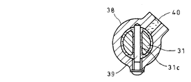
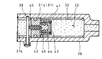
一方、前記作動油圧送機構33における第三ピストン31は、図6に示す如き形状を有しており、その軸心方向の前後位置にハウジング38の内周面に対し液密に摺接する二つの大径部31a,31bを備え且つ該各大径部31a,31bの相互間に軸心方向に延びるガイドスリット31cを開口している。
【0032】
そして、このガイドスリット31cには、ハウジング38側に固定されたストッパボルト39が貫通しており、第三ピストン31が最大にストロークしても該第三ピストン31とストッパボルト39とが干渉しないようになっている。
【0033】
尚、図7及び図8に示されている如く、第三ピストン31の各大径部31a,31bに挟まれた空間は、ハウジング38に設けたオイル孔40を介し図示しないリザーバタンクと接続されており、この空間には前記リザーバタンクから導かれた作動油が満たされるようになっている。
【0034】
更に、この第三ピストン31の第三圧力室32に面した先端部には、図9に詳細な内部構造を示す如きセンタバルブ41が装備されており、このセンタバルブ41内部に移動自在に収容されたセンタバルブ本体42が、スナップリング43との間に介装されたスプリング44により図9中の左側に着座するように付勢されている。
【0035】
ここで、このセンタバルブ41には、第三ピストン31の大径部31aの中心部分を軸心方向に摺動自在に貫通するノズル部45が一体的に具備されており、このノズル部45の軸心部分に穿設された流路を介してガイドスリット31c側と第三圧力室32側とが連通するようになっているが、常時はスプリング44の弾撥力に抗して図9中の左側に着座したセンタバルブ本体42のシール46により前記ガイドスリット31c側と第三圧力室32側とが隔絶され、第三ピストン31が初期位置まで退動している時にのみ前記ノズル部45が前記ストッパボルト39に干渉してセンタバルブ本体42が相対的に図9中の右側へ押し出され、これによりセンタバルブ本体42が弁座から離間してガイドスリット31c側と第三圧力室32側とが開通するようになっている。
【0036】
また、図1に示す如く、前述した各電動ボールネジ機構26側のハウジング35と作動油圧送機構33側のハウジング38との間を連結しているハウジング47には、前述した如き第一圧力室27や第二圧力室28が形成されている他、作動油圧送機構33の第二ピストン29と第三ピストン31との突き合わせ箇所を包囲するような第四圧力室48が形成されている。
【0037】
尚、第一圧力室27における第二圧力室28への連通箇所を挟んだ左右位置には、各電動ボールネジ機構26の第一ピストン25の作動量Aが確保されており、第二圧力室28にも同様の作動量Aが確保されている。
【0038】
更に、作動油圧送機構33の第三ピストン31の突き合わせ面には、隆起部31dが突設されていて第二ピストン29と第三ピストン31との突き合わせ箇所に僅かな隙間が形成されるようにしてあり、これにより前記隆起部31dの周囲と大径部31bとにおける第四圧力室48に面した箇所を受圧面として第三ピストン31が第二ピストン29から分離して進退動できるようになっており、また、第二ピストン29の第二圧力室28に面した部位にも、同様の隙間を確保する意図で隆起部29aが突設されている。
【0039】
そして、ハウジング47には、第四圧力室48に作動油を導くための給油口49が設けられており、この給油口49と前述の図2のクラッチペダル1により作動するマスタシリンダ2との間が流路接続されていて、クラッチペダル1の踏み込みにより生じた油圧が第四圧力室48にかけられるようにしてある。
【0040】
尚、図2中における50は車両速度を検出する車速センサ、51はリリースレバー4にリンク連結されてクラッチブースタ3によるストロークを検出するストロークセンサを夫々示しており、これら車速センサ50及びストロークセンサ51からの検出信号がオートマチックトランスミッションの制御をつかさどる制御装置18に入力されるようになっている。
【0041】
而して、運転席のモード切換スイッチ等を操作して制御装置18に手動モードを認識させた後、クラッチペダル1を踏み込んでマスタシリンダ2からアクチュエータ20の作動油圧送機構33における第四圧力室48に作動油を送り込むと、該第四圧力室48内で第三ピストン31の受圧面に油圧が作用して該第三ピストン31が第二ピストン29から分離して進出し、これによりセンタバルブ41が閉じてガイドスリット31c側と第三圧力室32側とが隔絶された状態となり、第三圧力室32から作動油が送り出されて図示しないクラッチが「断」となる。
【0042】
また、クラッチペダル1を戻すと、作動油が第四圧力室48からマスタシリンダ2に戻り、これにより第三ピストン31がスプリング30の復元力により初期位置まで退動し、これによりアクチュエータ20から送り出した作動油が該アクチュエータ20に戻されて図示しないクラッチが「接」となる。
【0043】
この際、第三ピストン31が初期位置まで退動すると、図9に示す如く、センタバルブ本体42のノズル部45がストッパボルト39に干渉してセンタバルブ本体42が相対的に図9中の右側へ押し出され、これによりセンタバルブ本体42が弁座から離間してガイドスリット31c側と第三圧力室32側とが開通し、該第三圧力室32の油圧が確実に零に戻される。
【0044】
尚、クラッチペダル1を踏み込んだ場合と戻した場合とにおけるクラッチブースタ3側の作動については、アクチュエータ20の詳細な構造を説明するのに先立ち既に説明してある通りであり、その実質的な内容が重複するものとなるので説明を割愛する。
【0045】
他方、運転席のモード切換スイッチ等を操作して制御装置18に自動モードを認識させれば、運転席のセレクトレバー操作等により変速が開始された際に、車速センサ50により例えば5km/hを超えた通常走行であることが確認されている条件下で、制御装置18により図1で左側のネジピッチが粗い方の電動ボールネジ機構26が選択され、該電動ボールネジ機構26の電動モータ22に向け制御装置18から電子信号が送られて電動モータ22によるボールネジ23の回転駆動が成され、これによりボールナット24がボールネジ23の軸心方向に速やかに移動して第一ピストン25が大きく進出し、該第一ピストン25により第一圧力室27から作動油圧送機構33の第二圧力室28へと作動油が送られ、これにより第二ピストン29を介して第三ピストン31がスプリング30の弾撥力に抗し押し出され、これにより第三圧力室32から作動油が送り出されて図示しないクラッチが「断」となる。
【0046】
また、自動変速が完了してエンジン回転とクラッチ回転の差が規定値内に収まると、制御装置18から左側の電動ボールネジ機構26の電動モータ22へ向けた電子信号により該電動モータ22が逆転され、これによりボールナット24がボールネジ23の軸心方向に戻されて第一ピストン25が退動し、該第一ピストン25による油圧で押し出されていた第二ピストン29及び第三ピストン31がスプリング30の復元力により初期位置まで退動し、これによりアクチュエータ20から送り出した作動油が該アクチュエータ20に戻されて図示しないクラッチが「接」となる。
【0047】
更に、運転席のモード切換スイッチ等を操作して制御装置18に自動モードを認識させた上で発進操作を含むクラッチの微動操作を行う場合には、車速センサ50により例えば5km/h以下の徐行運転であることが確認され且つストロークセンサ51によりクラッチブースタ3によるストロークが半クラッチ域にあることが確認されている条件下で、制御装置18により図1で右側のネジピッチが細かい方の電動ボールネジ機構26が選択され、該電動ボールネジ機構26の電動モータ22に向け制御装置18から電子信号が送られて電動モータ22によるボールネジ23の正逆転が繰り返され、これによりボールナット24がボールネジ23の軸心方向に小刻みに進退動して第一ピストン25も同様に進退動し、該第一ピストン25の進退動により第一圧力室27から作動油圧送機構33の第二圧力室28にかけての油圧の発生・解放が細かく繰り返され、これにより第二ピストン29及び第三ピストン31が小刻みに進退動する結果、図示しないクラッチの断接作動が小刻みに実現されて手動操作時の半クラッチ操作の如き微妙なクラッチ操作が可能となる。
【0048】
即ち、このようなアクチュエータ20を採用すれば、各電動ボールネジ機構26の電動モータ22によるボールネジ23の回転駆動を該ボールネジ23の軸心方向へ向けたボールナット24の進退作動に転換し、該ボールナット24を介した第一ピストン25の進退動作動の速度及び位置を制御装置18により精度良く制御することが可能となる上、通常走行時のクラッチの一般操作に関し、ネジピッチが粗い方の電動ボールネジ機構26を選択することで速やかなクラッチ作動速度が得られ、他方、発進操作を含むクラッチの微動操作に関し、ネジピッチが細かい方の電動ボールネジ機構26を選択することで小刻みなクラッチの断接作動が可能となるので、通常走行時におけるクラッチ作動速度の低下を招くことなく微妙なクラッチ操作の実現を図ることが可能となる。
【0049】
換言すれば、クラッチの微動操作ばかりを優先してネジピッチを細かくした電動ボールネジ機構26を単独で採用したものでは、通常走行時のクラッチの一般操作を行うにあたりクラッチ作動速度が遅くなって円滑な自動変速に支障をきたしかねないという不都合があるが、このような不都合をネジピッチの異なる一対の電動ボールネジ機構26を使い分けることで未然に回避するようにしているのである。
【0050】
従って、上記形態例によれば、各電動ボールネジ機構26の電動モータ22を電子制御することにより第一ピストン25の進退動作動の速度及び位置を精度良く制御することができ、しかも、ネジピッチの異なる一対の電動ボールネジ機構26を適宜に使い分けることで第一ピストン25の迅速な作動と微妙な作動の両方を同時に実現することもできるので、この第一ピストン25により第一圧力室27から第二圧力室28に作動油を導入して第二ピストン29によりスプリング30の弾撥力に抗し第三ピストン31を適切な速度及び長さだけ進出させることで第三圧力室32から作動油を押し出し、油量や油圧を繊細且つ正確に制御しながら作動油をクラッチブースタ3に供給することができ、延いては、発進時や停止時等における微妙なクラッチ操作を自動操作で行い得るようにしたクラッチコントロールシステムをクラッチ作動速度の低下を招くことなく実現できる。
【0051】
更に、特に本形態例においては、作動油圧送機構33の第二ピストン29と第三ピストン31との突き合わせ箇所を包囲するように第四圧力室48を設けると共に、該第四圧力室48に面した前記第三ピストン31の適宜箇所に受圧面を確保し、クラッチペダル1により作動するマスタシリンダ2と前記第四圧力室48とを流路接続するようにしているので、クラッチペダル1を踏み込んでマスタシリンダ2からアクチュエータ20の作動油圧送機構33における第四圧力室48に作動油を送り込み、該第四圧力室48内で第三ピストン31の受圧面に油圧を作用させることにより、該第三ピストン31を作動油圧送機構33の第二ピストン29から分離して進出させることができるので、何れかの電動ボールネジ機構26の電動モータ22を電子制御することによるクラッチの自動操作と、クラッチペダル1によるクラッチの手動操作とを併用して選択的に用いることができる。
【0052】
ただし、以上に説明した図1〜図9の形態例においては、電動ボールネジ機構26の電動モータ22を電子制御することによるクラッチの自動操作と、クラッチペダル1によるクラッチの手動操作とを併用したクラッチコントロールシステムとしているが、図2のクラッチペダル1から第四圧力室48にかけての油圧系を全て廃止し、常に各電動ボールネジ機構26により作動油圧送機構33からの作動油の油量や油圧を制御するようにした完全自動型のクラッチコントロールシステムとすることも可能である。
【0053】
尚、本発明のアクチュエータは、上述の形態例にのみ限定されるものではなく、必ずしも油圧系とエア系の両方の回路を有するクラッチブースタ(クラッチ段切手段)を備えたクラッチコントロールシステムのみならず、油圧系のみのクラッチコントロールシステムにも適用することが可能であり、更には、クラッチ以外の様々な油圧系の油量や油圧を制御するシステムにも適用することが可能であること、その他、本発明の要旨を逸脱しない範囲内において種々変更を加え得ることは勿論である。
【0054】
【発明の効果】
上記した本発明のアクチュエータによれば、下記の如き種々の優れた効果を奏し得る。
【0055】
(I)本発明の請求項1に記載の発明によれば、各電動ボールネジ機構の電動モータを電子制御することにより第一ピストンの進退動作動の速度及び位置を精度良く制御することができ、しかも、ネジピッチの異なる一対の電動ボールネジ機構を適宜に使い分けることで第一ピストンの迅速な作動と微妙な作動の両方を同時に実現することもできるので、この第一ピストンにより第一圧力室から第二圧力室に作動油を導入して第二ピストンによりスプリングの弾撥力に抗し第三ピストンを適切な速度及び長さだけ進出させることで第三圧力室から作動油を押し出すことができ、該作動油に関する油量や油圧を繊細且つ正確に制御することができる。
【0056】
(II)本発明の請求項2に記載の発明によれば、第四圧力室に対し給油口から作動油を送り込んで第四圧力室内で第三ピストンの受圧面に油圧を作用させることにより、該第三ピストンを第二ピストンから分離して進出させることができるので、何れかの電動ボールネジ機構の電動モータを電子制御することによる自動操作と、第四圧力室に対しペダル操作等で作動油を給排することによる手動操作とを併用して選択的に用いることができる。
【図面の簡単な説明】
【図1】本発明を実施する形態の一例を示す断面図である。
【図2】図1のアクチュエータを採用したクラッチコントロールシステムの一例を示す系統図である。
【図3】図2の要部についての作動説明図である。
【図4】図1の各電動ボールネジ機構の要部に関する分解図である。
【図5】図1の各電動ボールネジ機構のハウジングの単品図である。
【図6】図1の作動油圧送機構の第三ピストンの単品図である。
【図7】図1の作動油圧送機構のハウジングの単品図である。
【図8】図1のVIII−VIII矢視の断面図である。
【図9】図3の作動油圧送機構のセンタバルブについての詳細を示す断面図である。
【図10】従来例を示す系統図である。
【図11】図10の要部についての作動説明図である。
【符号の説明】
18 制御装置
20 アクチュエータ
22 電動モータ
23 ボールネジ
24 ボールナット
24b ボール
25 第一ピストン
26 電動ボールネジ機構
27 第一圧力室
28 第二圧力室
29 第二ピストン
30 スプリング
31 第三ピストン
32 第三圧力室
33 作動油圧送機構
48 第四圧力室
[0001]
BACKGROUND OF THE INVENTION
The present invention relates to an actuator suitable for use in a system for controlling the oil amount and oil pressure of a hydraulic system.
[0002]
[Prior art]
FIG. 10 shows an example of a conventional clutch control system employed in a large vehicle such as a large truck. In FIG. 10, 1 is a clutch pedal installed in the driver's seat, and 2 is operated by depressing the clutch pedal 1. The master cylinder 3 is a clutch booster that “disengages” a clutch (not shown) via the release lever 4. When the driver depresses the clutch pedal 1, the hydraulic oil is moved downstream of the clutch booster 3 by the master cylinder 2. The relay piston portion 6 is reached via the piston portion 5 ', where the relay piston body 7 slides to the left side in FIG. 10 and the poppet valve body 8 moves to the left side against the elastic force of the spring (not shown). The air circuit of the poppet valve unit 9 is opened (see FIG. 11), and the hydraulic oil is connected to the relay pipe. The hydraulic pressure is applied by reaching the preceding hydraulic piston portion 5 from the stone portion 6.
[0003]
When the air circuit of the poppet valve section 9 is opened, compressed air is sent from the air tank 10 to the double check valve 11 via the poppet valve section 9, and in the double check valve 11, the piston 12 in FIG. The compressed air is pushed rightward and introduced as it is into the cylinder shell 13 of the clutch booster 3 (see FIG. 11), whereby the piston 14 is assisted by the compressed air and resists the elastic force of a spring (not shown). The release lever 4 is pushed by the push rod 15 which is pushed into the left side and is connected to the piston 14, and the release lever 4 is actuated to disengage a clutch (not shown).
[0004]
When the clutch pedal 1 is returned, the hydraulic oil returns to the master cylinder 2 from the hydraulic piston portions 5 and 5 ′ and the relay piston portion 6 before and after the clutch booster 3, and on the other hand, the relay piston body 7 of the relay piston portion 6 and The poppet valve body 8 of the poppet valve section 9 is returned to the right side in FIG. 10 by the restoring force of a spring (not shown), the air circuit for the air tank 10 side is closed, and the compressed air behind the piston 14 in the cylinder shell 13 is double check valve. 11 passes through the passage in the relay piston main body 7 and enters the front of the piston 14 in the cylinder shell 13, and is further exhausted from the joint portion 17 of the relay valve 16 via the cylinder exhaust port of the clutch booster 3. The push rod 15 connected to the When the lease lever 4 is returned, a clutch (not shown) is brought into “contact”.
[0005]
The manual operation by the clutch pedal 1 has been described above. However, in the clutch control system shown here, the automatic operation can be performed by the electronic control of the control device 18 that controls the automatic transmission. More specifically, when a shift is started by operating a select lever at the driver's seat or the like, an electronic signal is sent from the control device 18 to the normally closed clutch control electromagnetic valve 19 and the port of the clutch control electromagnetic valve 19 is set. Opening, thereby sending compressed air from the air tank 10 to the normally closed relay valve 16, and using this as an air signal, the port opens to send compressed air from another path through the relay valve 16 to the double check valve 11, In the double check valve 11, the piston 12 is pushed to the left in FIG. Then, the compressed air is introduced as it is into the cylinder shell 13 of the clutch booster 3, whereby the piston 14 is pushed to the left in FIG. 10 against the elastic force of a spring (not shown) and connected to the piston 14. The release lever 4 is pushed by the push rod 15 and the release lever 4 is operated to disengage the clutch (not shown).
[0006]
Further, when the automatic shift is completed and the difference between the engine rotation and the clutch rotation falls within the specified value, the electronic signal from the control device 18 to the clutch control electromagnetic valve 19 is stopped, whereby the output port of the relay valve 16 is exhausted. The compressed air that has been in the cylinder shell 13 of the clutch booster 3 is discharged from the exhaust port of the relay valve 16 to the joint portion 17 via the double check valve 11, and the piston 14 is restored by the return force on the clutch side. Is returned to the right side in FIG. 10 so that the clutch is "engaged".
[0007]
In the conventional clutch control system as described above, the manual operation by the clutch pedal 1 and the automatic operation by the electronic control of the control device 18 can be selected as appropriate and can be selected as appropriate. When a delicate clutch operation is required, the manual operation by the clutch pedal 1 is selected. Such a delicate clutch operation is automatically turned on / off by a large volume of compressed air. It is technically difficult to substitute for operation, and this is a major factor that hinders full automation of clutch operation in large vehicles.
[0008]
As prior art documents related to this type of clutch control system, the following Patent Document 1, Patent Document 2, Patent Document 3, and the like already exist.
[0009]
[Patent Document 1]
JP 2000-179580 A [Patent Document 2]
JP 2002-147496 A [Patent Document 3]
Japanese Patent Laid-Open No. 2002-213490
[Problems to be solved by the invention]
However, an actuator that can cope with the delicate clutch operation in the clutch control system of FIGS. 10 and 11 as described above, that is, an actuator that can delicately and accurately control the oil amount and hydraulic pressure is still in practical use. However, the provision of such an actuator is desired to contribute to fully automatic clutch operation.
[0011]
The present invention has been made in view of the above circumstances, and an object thereof is to provide an actuator capable of delicately and accurately controlling the oil amount and hydraulic pressure.
[0012]
[Means for Solving the Problems]
The present invention relates to a pair of electric ball screw mechanisms having different screw pitches, in which a ball screw is rotated by an electric motor and a first piston is moved forward and backward through a ball nut screwed to the ball screw. A second piston having a second pressure chamber communicating with the first pressure chamber and facing the first pressure chamber in a coaxial manner and arranged in a coaxial manner, and a spring that is elastically repelled by a hydraulic pressure in the second pressure chamber. The present invention relates to an actuator characterized in that an operating hydraulic pressure feeding mechanism that moves a third piston against a force and pushes hydraulic oil from a third pressure chamber is arranged in parallel with each electric ball screw mechanism. .
[0013]
Thus, according to such an actuator, the rotation drive of the ball screw by the electric motor of any one of the electric ball screw mechanisms is converted into the forward / backward movement of the ball nut in the axial direction of the ball screw, and the ball nut is The speed and position of the forward / backward movement of the first piston is controlled with high accuracy. When hydraulic oil is introduced from the first pressure chamber to the second pressure chamber by the first piston, the second piston The third piston is advanced by an appropriate speed and length against the spring resilience of the spring, and hydraulic oil is pushed out from the third pressure chamber, and the oil amount and hydraulic pressure related to the hydraulic oil are controlled delicately and accurately. become.
[0014]
In addition, by selecting the electric ball screw mechanism with the coarser screw pitch, the ball nut can be quickly moved back and forth in the axial direction of the ball screw. On the other hand, by selecting the electric ball screw mechanism with the finer screw pitch, The ball nut can be moved back and forth in the axial direction in small increments, so when applied to a system that controls the oil amount and oil pressure of the hydraulic system, the system can be used by properly using a pair of electric ball screw mechanisms with different screw pitches. Both quick and subtle operation on the side will be realized at the same time.
[0015]
In the present invention, a fourth pressure chamber is provided so as to surround the abutting portion between the second piston and the third piston of the operating hydraulic pressure feeding mechanism, and the third piston facing the fourth pressure chamber is appropriately provided. A pressure receiving surface may be secured at a location, and the master cylinder operated by the clutch pedal and the fourth pressure chamber may be connected to each other through a flow path.
[0016]
If it does in this way, hydraulic oil will be sent from the oil supply opening to the 4th pressure chamber, and this 3rd piston will be separated from the 2nd piston by making oil pressure act on the pressure receiving surface of the 3rd piston in this 4th pressure chamber. The automatic operation by electronically controlling the electric motor of one of the electric ball screw mechanisms and the manual operation by supplying and discharging hydraulic oil to the fourth pressure chamber by pedal operation etc. It can be selectively used in combination.
[0017]
DETAILED DESCRIPTION OF THE INVENTION
Embodiments of the present invention will be described below with reference to the drawings.
[0018]
1 to 9 show an example of an embodiment for carrying out the present invention, and portions denoted by the same reference numerals as those in FIG. 10 represent the same items.
[0019]
FIG. 1 is a cross-sectional view showing a detailed structure of the actuator 20 of this embodiment, and FIG. 2 shows an example of a clutch control system employing the actuator 20 of FIG.
[0020]
Prior to describing the detailed structure of the actuator 20, the outline of the clutch control system of FIG. 2 will be described. In this clutch control system, the master cylinder 2 that operates when the clutch pedal 1 is depressed, and the release The actuator 20 is provided between a clutch booster 3 (clutch gear disengaging means) for connecting / disconnecting a clutch (not shown) via the lever 4, and a manual operation by the clutch pedal 1 and control of the automatic transmission 18 are controlled. The automatic operation by electronic control can be selectively used properly.
[0021]
In the clutch booster 3 shown here, the subsequent hydraulic piston portion is abolished and only the previous hydraulic piston portion 5 is provided, and the hydraulic oil fed from the actuator 20 is supplied to the hydraulic piston portion 5. 2 to reach the relay piston 6 where the relay piston body 7 slides to the left in FIG. 2 and the poppet valve body 8 is pushed to the left against the spring repelling force (not shown). Thus, the air circuit of the poppet valve unit 9 is opened (see FIG. 3).
[0022]
When the air circuit of the poppet valve section 9 is opened, the compressed air from the air tank 10 is introduced into the cylinder shell 13 of the clutch booster 3 via the poppet valve section 9, whereby the piston 14 assists the compressed air. 2 is pushed to the left in FIG. 2 against the elastic force of a spring (not shown), the release lever 4 is pushed by the push rod 15 connected to the piston 14, and the release lever 4 is actuated and is not shown. The clutch is "disengaged".
[0023]
Further, when the hydraulic oil sent out from the actuator 20 is returned to the actuator 20, the hydraulic oil is extracted from the hydraulic piston portion 5 and the relay piston portion 6 of the clutch booster 3, thereby the relay piston body of the relay piston portion 6. 7 and the poppet valve body 8 of the poppet valve section 9 are returned to the right side in FIG. 2 by the restoring force of a spring (not shown), the air circuit for the air tank 10 side is closed, and the compressed air behind the piston 14 in the cylinder shell 13 is relayed A push rod 15 connected to the piston 14 passes through a new passage in the piston body 7 and is exhausted into the atmosphere from the exhaust port 21 (a part of the compressed air also enters the front of the piston 14 in the cylinder shell 13). Is shown by retracting to the original position and returning the release lever 4 Clutch is made in such a way that "contact".
[0024]
Hereinafter, a detailed structure of the actuator 20 according to the present embodiment will be described with reference to FIGS. 1 and 4 to 9.
[0025]
As shown in FIG. 1, the actuator 20 is configured such that a ball screw 23 is rotated by an electric motor 22 and a first piston 25 is moved forward and backward via a ball nut 24 screwed to the ball screw 23 via a ball 24b. A pair of electric ball screw mechanisms 26 having different screw pitches are arranged in series on the same axis with the first pistons 25 facing each other through the first pressure chamber 27, and the first pressure chamber 27 communicates with the first pressure chamber 27. The second piston 29 is provided with two pressure chambers 28 and is advanced by the hydraulic pressure of the second pressure chamber 28, and the third piston 31 is advanced against the elastic force of the spring 30, so that the clutch booster 3 A hydraulic pressure feed mechanism 33 that pushes hydraulic oil to the hydraulic piston portion 5 is arranged in parallel with the electric ball screw mechanisms 26. It has become concrete.
[0026]
Here, the electric ball screw mechanism 26 on the left side in FIG. 1 is formed such that the screw pitch of the ball screw 23 is relatively coarse, and the first piston 25 is greatly advanced and retracted with respect to the rotation of the ball screw 23. On the other hand, the electric ball screw mechanism 26 on the right side has a relatively small screw pitch of the ball screw 23, and the first piston 25 is moved forward and backward with respect to the rotation of the ball screw 23.
[0027]
The first piston 25 in each of the electric ball screw mechanisms 26 has a shape as shown in FIG. 4, and a cup-shaped collar 34 is bolted to a flange portion 25 a on the base end side. The ball nut 24 is integrally fitted inside.
[0028]
When the ball nut 24 is integrally fitted and held in the collar 34, a part of the collar 34 is caulked from the outside as the caulking groove 24a of the ball nut 24 to be crimped.
[0029]
The unit of the ball nut 24, the collar 34, and the first piston 25 thus integrated is held by a housing 35 as shown in FIG. Guide protrusions 25b provided on the upper and lower ends of the flange portion 25a of the first piston 25 are slidable in the axial direction with respect to a part of the formed spline groove 35a (the remaining spline groove 35a forms a grease reservoir). To prevent rotation in the circumferential direction.
[0030]
The ball screw 23 to which the ball nut 24 is screwed is held at its base end portion in a housing 36 so as to be rotatable by a bearing 37, and the electric motor 22 is bolted to the housing 36. The output shaft 22a is integrally connected.
[0031]
On the other hand, the third piston 31 in the operating hydraulic pressure feeding mechanism 33 has a shape as shown in FIG. 6, and the two pistons are in fluid-tight sliding contact with the inner peripheral surface of the housing 38 at front and rear positions in the axial direction. A guide slit 31c having large diameter portions 31a and 31b and extending in the axial direction is opened between the large diameter portions 31a and 31b.
[0032]
A stopper bolt 39 fixed on the housing 38 side passes through the guide slit 31c so that the third piston 31 and the stopper bolt 39 do not interfere with each other even when the third piston 31 is stroked to the maximum. It has become.
[0033]
As shown in FIGS. 7 and 8, the space between the large diameter portions 31 a and 31 b of the third piston 31 is connected to a reservoir tank (not shown) via an oil hole 40 provided in the housing 38. This space is filled with hydraulic oil introduced from the reservoir tank.
[0034]
Further, a center valve 41 having a detailed internal structure shown in FIG. 9 is provided at the tip of the third piston 31 facing the third pressure chamber 32, and is housed in the center valve 41 so as to be movable. The center valve main body 42 is urged so as to be seated on the left side in FIG. 9 by a spring 44 interposed between the center ring main body 42 and the snap ring 43.
[0035]
Here, the center valve 41 is integrally provided with a nozzle portion 45 that slidably passes through the central portion of the large diameter portion 31a of the third piston 31 in the axial direction. Although the guide slit 31c side and the third pressure chamber 32 side communicate with each other through a flow path drilled in the axial center portion, the guide slit 31c and the third pressure chamber 32 side always communicate with each other in FIG. The guide slit 31c side and the third pressure chamber 32 side are isolated from each other by the seal 46 of the center valve body 42 seated on the left side, and the nozzle portion 45 is moved only when the third piston 31 is retracted to the initial position. The center valve body 42 is pushed relatively to the right in FIG. 9 by interfering with the stopper bolt 39, whereby the center valve body 42 is separated from the valve seat, and the guide slit 31c side, the third pressure chamber 32 side, and so on. But So that the passing.
[0036]
Further, as shown in FIG. 1, the housing 47 connecting the housing 35 on the electric ball screw mechanism 26 side and the housing 38 on the hydraulic pressure feeding mechanism 33 side has a first pressure chamber 27 as described above. In addition to the formation of the second pressure chamber 28, a fourth pressure chamber 48 is formed so as to surround the abutting portion between the second piston 29 and the third piston 31 of the hydraulic pressure feeding mechanism 33.
[0037]
The first pressure chamber 27 has an operation amount A of the first piston 25 of each electric ball screw mechanism 26 at the left and right positions of the first pressure chamber 27 across the communication point to the second pressure chamber 28. A similar operation amount A is also secured.
[0038]
Further, a protruding portion 31d is projected from the abutting surface of the third piston 31 of the hydraulic pressure feeding mechanism 33 so that a slight gap is formed at the abutting portion between the second piston 29 and the third piston 31. As a result, the third piston 31 can move forward and backward by separating from the second piston 29 with the portion facing the fourth pressure chamber 48 around the raised portion 31d and the large diameter portion 31b as a pressure receiving surface. In addition, a raised portion 29a is projected from the portion of the second piston 29 facing the second pressure chamber 28 with the intention of securing a similar gap.
[0039]
The housing 47 is provided with an oil supply port 49 for guiding hydraulic oil to the fourth pressure chamber 48, and between the oil supply port 49 and the master cylinder 2 operated by the clutch pedal 1 shown in FIG. Is connected to the flow path so that the hydraulic pressure generated by the depression of the clutch pedal 1 is applied to the fourth pressure chamber 48.
[0040]
2, reference numeral 50 denotes a vehicle speed sensor that detects the vehicle speed, and 51 denotes a stroke sensor that is linked to the release lever 4 and detects a stroke by the clutch booster 3, and these vehicle speed sensor 50 and stroke sensor 51 are shown. Is input to the control device 18 which controls the automatic transmission.
[0041]
Thus, after operating the mode selector switch of the driver's seat to make the control device 18 recognize the manual mode, the clutch pedal 1 is depressed and the fourth pressure chamber in the operating hydraulic pressure feeding mechanism 33 of the actuator 20 from the master cylinder 2 is reached. When hydraulic oil is fed into 48, hydraulic pressure acts on the pressure receiving surface of the third piston 31 in the fourth pressure chamber 48, and the third piston 31 separates from the second piston 29 and advances. 41 closes and the guide slit 31c side and the third pressure chamber 32 side are isolated from each other, hydraulic oil is sent out from the third pressure chamber 32, and the clutch (not shown) is disengaged.
[0042]
When the clutch pedal 1 is returned, the hydraulic oil returns from the fourth pressure chamber 48 to the master cylinder 2, whereby the third piston 31 is retracted to the initial position by the restoring force of the spring 30, and is thereby sent out from the actuator 20. The hydraulic oil thus returned is returned to the actuator 20 and a clutch (not shown) is brought into “contact”.
[0043]
At this time, when the third piston 31 is retracted to the initial position, as shown in FIG. 9, the nozzle portion 45 of the center valve body 42 interferes with the stopper bolt 39 and the center valve body 42 is relatively moved to the right side in FIG. As a result, the center valve body 42 is separated from the valve seat, the guide slit 31c side and the third pressure chamber 32 side are opened, and the hydraulic pressure in the third pressure chamber 32 is reliably returned to zero.
[0044]
The operation on the clutch booster 3 side when the clutch pedal 1 is depressed and returned is as already described prior to the detailed structure of the actuator 20, and its substantial contents. Will be omitted because it will overlap.
[0045]
On the other hand, if the control device 18 recognizes the automatic mode by operating the driver's seat mode changeover switch or the like, the vehicle speed sensor 50 sets, for example, 5 km / h when the gear shift is started by operating the select lever of the driver's seat. Under the condition that it is confirmed that the normal running is exceeded, the control device 18 selects the electric ball screw mechanism 26 having the coarser screw pitch on the left side in FIG. 1 and controls the electric ball screw mechanism 26 toward the electric motor 22. An electronic signal is sent from the device 18 and the ball screw 23 is rotationally driven by the electric motor 22. As a result, the ball nut 24 quickly moves in the axial direction of the ball screw 23, and the first piston 25 advances greatly. The hydraulic oil is sent from the first pressure chamber 27 to the second pressure chamber 28 of the hydraulic pressure feeding mechanism 33 by the first piston 25, thereby the second piston Third piston 31 through 9 are pushed against the resilience of the spring 30, thereby the clutch (not shown) hydraulic fluid is fed from the third pressure chamber 32 becomes "OFF".
[0046]
When the automatic shift is completed and the difference between the engine rotation and the clutch rotation falls within a specified value, the electric motor 22 is reversed by an electronic signal from the control device 18 to the electric motor 22 of the left electric ball screw mechanism 26. As a result, the ball nut 24 is returned in the axial direction of the ball screw 23 and the first piston 25 is retracted, and the second piston 29 and the third piston 31 that have been pushed out by the hydraulic pressure of the first piston 25 are moved by the spring 30. With this restoring force, the hydraulic oil is retracted to the initial position, so that the hydraulic oil sent from the actuator 20 is returned to the actuator 20 and a clutch (not shown) is brought into “contact”.
[0047]
Further, when a fine movement operation of the clutch including a start operation is performed after the control device 18 recognizes the automatic mode by operating the mode changeover switch or the like of the driver's seat, the vehicle speed sensor 50 slows down, for example, at a speed of 5 km / h or less. The electric ball screw mechanism in which the screw pitch on the right side in FIG. 1 is finer by the control device 18 under the condition that the operation is confirmed and the stroke sensor 51 confirms that the stroke by the clutch booster 3 is in the half clutch range. 26 is selected, an electronic signal is sent from the control device 18 toward the electric motor 22 of the electric ball screw mechanism 26, and the forward and reverse rotation of the ball screw 23 by the electric motor 22 is repeated, whereby the ball nut 24 becomes the axis of the ball screw 23. The first piston 25 moves forward and backward in small increments in the direction. As a result, the generation and release of the hydraulic pressure from the first pressure chamber 27 to the second pressure chamber 28 of the working hydraulic pressure feeding mechanism 33 is finely repeated by the movement, and as a result, the second piston 29 and the third piston 31 move forward and backward in small increments. A clutch connecting / disconnecting operation (not shown) is realized in small steps, and a delicate clutch operation such as a half-clutch operation at the time of manual operation becomes possible.
[0048]
That is, if such an actuator 20 is employed, the rotational drive of the ball screw 23 by the electric motor 22 of each electric ball screw mechanism 26 is converted to an advance / retreat operation of the ball nut 24 in the axial direction of the ball screw 23, The speed and position of the forward / backward movement of the first piston 25 via the nut 24 can be accurately controlled by the control device 18, and the electric ball screw with the coarser screw pitch is used for general operation of the clutch during normal running. By selecting the mechanism 26, a quick clutch operation speed can be obtained. On the other hand, regarding the fine movement operation of the clutch including the starting operation, the connection and disconnection operation of the clutch can be performed little by little by selecting the electric ball screw mechanism 26 having a smaller screw pitch. Because it becomes possible, delicate clutch operation without causing a decrease in clutch operating speed during normal driving It is possible to achieve the realization.
[0049]
In other words, in the case where the electric ball screw mechanism 26 having a finer screw pitch with priority given only to the fine movement operation of the clutch alone is employed, the clutch operating speed becomes slow and the smooth automatic operation is performed when performing the general operation of the clutch during normal running. Although there is an inconvenience that the shift may be hindered, such an inconvenience is avoided by using a pair of electric ball screw mechanisms 26 having different screw pitches.
[0050]
Therefore, according to the above embodiment, the speed and position of the first piston 25 can be accurately controlled by electronically controlling the electric motor 22 of each electric ball screw mechanism 26, and the screw pitch is different. Both the rapid operation and the delicate operation of the first piston 25 can be realized at the same time by properly using the pair of electric ball screw mechanisms 26. Therefore, the first pressure chamber 27 allows the second pressure to be increased by the first piston 25. Hydraulic oil is introduced into the chamber 28, and the hydraulic oil is pushed out from the third pressure chamber 32 by advancing the third piston 31 by an appropriate speed and length against the elastic force of the spring 30 by the second piston 29. Hydraulic oil can be supplied to the clutch booster 3 while delicately and accurately controlling the oil amount and hydraulic pressure. The clutch control system adapted to be carried out latch operation in automatic operation can be achieved without lowering the clutch operating speed.
[0051]
Further, particularly in the present embodiment, a fourth pressure chamber 48 is provided so as to surround the abutting portion between the second piston 29 and the third piston 31 of the operating hydraulic pressure feeding mechanism 33, and the fourth pressure chamber 48 faces the surface. Since the pressure receiving surface is secured at an appropriate position of the third piston 31 and the master cylinder 2 operated by the clutch pedal 1 and the fourth pressure chamber 48 are connected to each other, the clutch pedal 1 is depressed. The hydraulic oil is fed from the master cylinder 2 to the fourth pressure chamber 48 in the hydraulic pressure feeding mechanism 33 of the actuator 20, and the hydraulic pressure is applied to the pressure receiving surface of the third piston 31 in the fourth pressure chamber 48. Since the piston 31 can be separated and advanced from the second piston 29 of the operating hydraulic pressure feeding mechanism 33, the electric motor 22 of any electric ball screw mechanism 26. And automatic operation of the clutch due to the electronic control, a combination of a manual operation of the clutch by the clutch pedal 1 can be used selectively.
[0052]
However, in the embodiment described above with reference to FIGS. 1 to 9, a clutch using both automatic operation of the clutch by electronically controlling the electric motor 22 of the electric ball screw mechanism 26 and manual operation of the clutch by the clutch pedal 1. Although the control system is used, the hydraulic system from the clutch pedal 1 to the fourth pressure chamber 48 of FIG. 2 is completely abolished, and the oil amount and hydraulic pressure of the hydraulic oil from the hydraulic pressure feed mechanism 33 are always controlled by each electric ball screw mechanism 26. It is possible to provide a fully automatic clutch control system.
[0053]
The actuator of the present invention is not limited only to the above-described embodiment, but is not limited to a clutch control system including a clutch booster (clutch disconnection means) having both hydraulic and air circuits. It can be applied to a clutch control system only for a hydraulic system, and can also be applied to a system for controlling the oil amount and hydraulic pressure of various hydraulic systems other than the clutch. Of course, various modifications can be made without departing from the scope of the present invention.
[0054]
【The invention's effect】
According to the actuator of the present invention described above, various excellent effects as described below can be obtained.
[0055]
(I) According to the invention described in claim 1 of the present invention, the speed and position of the forward / backward movement of the first piston can be accurately controlled by electronically controlling the electric motor of each electric ball screw mechanism, In addition, by appropriately using a pair of electric ball screw mechanisms having different screw pitches, it is possible to simultaneously realize both a quick operation and a subtle operation of the first piston. The hydraulic oil can be pushed out from the third pressure chamber by introducing the hydraulic oil into the pressure chamber and advancing the third piston by an appropriate speed and length against the elastic force of the spring by the second piston, The oil amount and hydraulic pressure relating to the hydraulic oil can be controlled delicately and accurately.
[0056]
(II) According to the invention described in claim 2 of the present invention, by sending hydraulic oil from the oil supply port to the fourth pressure chamber and applying hydraulic pressure to the pressure receiving surface of the third piston in the fourth pressure chamber, Since the third piston can be separated and advanced from the second piston, the hydraulic oil can be operated automatically by electronically controlling the electric motor of any of the electric ball screw mechanisms and by operating the pedal with respect to the fourth pressure chamber. Can be selectively used in combination with manual operation by feeding and discharging.
[Brief description of the drawings]
FIG. 1 is a cross-sectional view showing an example of an embodiment of the present invention.
FIG. 2 is a system diagram showing an example of a clutch control system employing the actuator of FIG.
FIG. 3 is an operation explanatory diagram for a main part of FIG. 2;
4 is an exploded view of the main part of each electric ball screw mechanism of FIG. 1. FIG.
5 is a single item diagram of a housing of each electric ball screw mechanism of FIG. 1. FIG.
6 is a single item diagram of a third piston of the working hydraulic pressure feeding mechanism of FIG. 1; FIG.
7 is a single item diagram of a housing of the hydraulic pressure feeding mechanism in FIG. 1. FIG.
8 is a cross-sectional view taken along the line VIII-VIII in FIG. 1;
9 is a cross-sectional view showing details of a center valve of the hydraulic pressure feeding mechanism in FIG. 3. FIG.
FIG. 10 is a system diagram showing a conventional example.
FIG. 11 is an operation explanatory diagram for the main part of FIG. 10;
[Explanation of symbols]
18 Control Device 20 Actuator 22 Electric Motor 23 Ball Screw 24 Ball Nut 24b Ball 25 First Piston 26 Electric Ball Screw Mechanism 27 First Pressure Chamber 28 Second Pressure Chamber 29 Second Piston 30 Spring 31 Third Piston 32 Third Pressure Chamber 33 Operation Hydraulic feed mechanism 48 Fourth pressure chamber

Claims (2)

電動モータによりボールネジを回転駆動し且つ該ボールネジに螺合したボールナットを介し第一ピストンを進退動せしめるようにしたネジピッチの異なる一対の電動ボールネジ機構を、互いの第一ピストン同士を第一圧力室を介し対峙させて同軸上に直列配置すると共に、前記第一圧力室に連通した第二圧力室を備え且つ該第二圧力室の油圧で進出する第二ピストンによりスプリングの弾撥力に抗し第三ピストンを進出させて第三圧力室から作動油を押し出すようにした作動油圧送機構を、前記各電動ボールネジ機構に並列配置したことを特徴とするアクチュエータ。A pair of electric ball screw mechanisms having different screw pitches are configured such that a ball screw is rotated by an electric motor and a first piston is moved forward and backward through a ball nut screwed to the ball screw. And a second pressure chamber that communicates with the first pressure chamber and that is advanced by the hydraulic pressure of the second pressure chamber to resist the spring repelling force of the spring. An actuator characterized in that a hydraulic pressure feed mechanism in which a third piston is advanced to push out hydraulic oil from a third pressure chamber is arranged in parallel with each of the electric ball screw mechanisms. 作動油圧送機構の第二ピストンと第三ピストンとの突き合わせ箇所を包囲するように第四圧力室を設けると共に、該第四圧力室に面した前記第三ピストンの適宜箇所に受圧面を確保し、前記第四圧力室に作動油を導く給油口を設けたことを特徴とする請求項1に記載のアクチュエータ。A fourth pressure chamber is provided so as to surround the abutting portion between the second piston and the third piston of the operating hydraulic pressure feeding mechanism, and a pressure receiving surface is secured at an appropriate portion of the third piston facing the fourth pressure chamber. The actuator according to claim 1, further comprising an oil supply port that guides hydraulic oil to the fourth pressure chamber.
JP2002329495A 2002-11-13 2002-11-13 Actuator Expired - Fee Related JP4020759B2 (en)

Priority Applications (1)

Application Number Priority Date Filing Date Title
JP2002329495A JP4020759B2 (en) 2002-11-13 2002-11-13 Actuator

Applications Claiming Priority (1)

Application Number Priority Date Filing Date Title
JP2002329495A JP4020759B2 (en) 2002-11-13 2002-11-13 Actuator

Publications (2)

Publication Number Publication Date
JP2004162811A JP2004162811A (en) 2004-06-10
JP4020759B2 true JP4020759B2 (en) 2007-12-12

Family

ID=32807472

Family Applications (1)

Application Number Title Priority Date Filing Date
JP2002329495A Expired - Fee Related JP4020759B2 (en) 2002-11-13 2002-11-13 Actuator

Country Status (1)

Country Link
JP (1) JP4020759B2 (en)

Also Published As

Publication number Publication date
JP2004162811A (en) 2004-06-10

Similar Documents

Publication Publication Date Title
JP3919657B2 (en) Actuator
JP3942089B2 (en) Clutch control system
JP4020759B2 (en) Actuator
JP2005048924A (en) Hydraulic clutch operating device
JP3942094B2 (en) Clutch control system
JP3896328B2 (en) Clutch control system
JP3896332B2 (en) Clutch control system
JP6648652B2 (en) Clutch system
JP2003307203A (en) Actuator
JP3906162B2 (en) Actuator
JP3704751B2 (en) Fluid pressure generator
JP4092226B2 (en) Clutch control system
JP3869143B2 (en) Automotive clutch device
JP2003307238A (en) Clutch control system
JP2004162877A (en) Actuator
JP2008157369A (en) Clutch control system
JP2005163992A (en) Hydraulic clutch operation device
JPH0971144A (en) Operating device for master cylinder
JP2004162876A (en) Clutch control system
JP2528895Y2 (en) Clutch booster
JP3704757B2 (en) Fluid pressure generator
JPH0925949A (en) Clutch on-and-off apparatus
JP2005083473A (en) Hydraulic clutch operating device
JPS6221778Y2 (en)
JP2003314590A (en) Clutch control system

Legal Events

Date Code Title Description
A621 Written request for application examination

Free format text: JAPANESE INTERMEDIATE CODE: A621

Effective date: 20050412

A977 Report on retrieval

Free format text: JAPANESE INTERMEDIATE CODE: A971007

Effective date: 20070126

A131 Notification of reasons for refusal

Free format text: JAPANESE INTERMEDIATE CODE: A131

Effective date: 20070130

TRDD Decision of grant or rejection written
A01 Written decision to grant a patent or to grant a registration (utility model)

Free format text: JAPANESE INTERMEDIATE CODE: A01

Effective date: 20070919

A61 First payment of annual fees (during grant procedure)

Free format text: JAPANESE INTERMEDIATE CODE: A61

Effective date: 20070925

FPAY Renewal fee payment (event date is renewal date of database)

Free format text: PAYMENT UNTIL: 20101005

Year of fee payment: 3

R150 Certificate of patent or registration of utility model

Free format text: JAPANESE INTERMEDIATE CODE: R150

FPAY Renewal fee payment (event date is renewal date of database)

Free format text: PAYMENT UNTIL: 20111005

Year of fee payment: 4

FPAY Renewal fee payment (event date is renewal date of database)

Free format text: PAYMENT UNTIL: 20111005

Year of fee payment: 4

FPAY Renewal fee payment (event date is renewal date of database)

Free format text: PAYMENT UNTIL: 20121005

Year of fee payment: 5

FPAY Renewal fee payment (event date is renewal date of database)

Free format text: PAYMENT UNTIL: 20121005

Year of fee payment: 5

FPAY Renewal fee payment (event date is renewal date of database)

Free format text: PAYMENT UNTIL: 20131005

Year of fee payment: 6

LAPS Cancellation because of no payment of annual fees