JP4020487B2 - Brake shoe for drum brake - Google Patents
Brake shoe for drum brake Download PDFInfo
- Publication number
- JP4020487B2 JP4020487B2 JP13262198A JP13262198A JP4020487B2 JP 4020487 B2 JP4020487 B2 JP 4020487B2 JP 13262198 A JP13262198 A JP 13262198A JP 13262198 A JP13262198 A JP 13262198A JP 4020487 B2 JP4020487 B2 JP 4020487B2
- Authority
- JP
- Japan
- Prior art keywords
- shoe
- rim
- positioning
- projection
- brake
- Prior art date
- Legal status (The legal status is an assumption and is not a legal conclusion. Google has not performed a legal analysis and makes no representation as to the accuracy of the status listed.)
- Expired - Lifetime
Links
Images


Landscapes
- Braking Arrangements (AREA)
Description
【0001】
【発明の属する技術分野】
本発明はドラムブレーキ用のブレーキシューに係わり、殊にシューリムとシューウェブの突起溶接時における両者の位置決め構造に関するものである。
【0002】
【従来の技術】
この種ドラムブレーキ用のブレーキシューは、例えば図8〜図11に示すような構成が普通である。図8はブレーキシュー2を構成するシューリム3とシューウェブ4の突起溶接前の状態図であって、略短冊状のシューリム3には、その幅方向の両側部に各3つの直角に折曲されたビード部3aが形成されており、このビード部3aが図示しない公知のドラムブレーキ装置の静止部材上に可動的に載置される。又、幅方向の中心線上には複数の溶接突起3b(本図では7箇所)が突出形成されていると共に、周方向の適当な位置に位置決め用の穴3cが穿設されている。通常、この位置決め用の穴3cは図9の拡大図に示すような矩形穴、或いは図10に示すような丸穴であり、シューウェブ4に対するシューリム3の周方向のずれを制限できる形状である。
【0003】
略三日月状のシューウェブ4には、図示しないシューホールドピンを遊嵌貫通せしめる挿通穴4aや図示しないシューリターンスプリングを掛止する切欠き4fが適宜形成されると共に、その外周には前記シューリム3の位置決め用の穴3cに周方向に僅かな隙間を存して嵌合する位置決め用の突起4cが形成されている。
通常、前記シューリム3とシューウェブ4は何れもコイル材からプレス順送成形にて加工され、シューリム3に就いてはその溶接突起3bがシューウェブ4の外周面に略沿うように、プレス曲げやローラ曲げ加工によってR曲げ成形されている。
【0004】
そして、シューリム3とシューウェブ4の突起溶接は図8に示すように、下部電極(図示せず)で支持したシューウェブ4の外周面上に、該シューウェブ4の位置決め用の突起4cにシューリム3の位置決め用の穴3cを嵌合して位置合せしながら該シューリム3の溶接突起3bを載置する。しかる後、二点鎖線で示す上部電極6を下降させ所定の溶接条件で以て両者は一体化される。一体化されたシューリム3とシューウェブ4には適宜防錆処理が施された後に、図示しないブレーキドラムに摩擦係合するブレーキライニング5が図11に示すように、シューリムの外周面に接着やリベットで以て固着されてブレーキシュー2が完成する。
【0005】
【発明が解決しようとする課題】
前記したドラムブレーキ用のブレーキシューには次のような問題点がある。
【0006】
<イ> 突起溶接後に、シューウェブ4の位置決め用の突起4cがシューリム3のブレーキライニング5接合面から突出すると、ブレーキライニング5の固着時にこれが折損したり、シューリム3との間に隙間ができて強度不足を招いたり、或いは、前記隙間が起因して制動時に振動を誘発する等の問題が生じるから、前記位置決め用の突起4cをシューリム3のブレーキライニング5接合面から突出させない設計が前提条件となる。
然して、従来のように、平板状のシューリム3に単に位置決め用の穴3cを穿設しただけでは、溶接突起3bの高さだけシューウェブ4の位置決め用の突起4cとの掛かり代が少なくなるため、前記位置決め用の突起4cに対する位置決め用の穴3cの位置合せが面倒で作業能率の低下を招いていた。
<ロ> 殊に、下部電極と上部電極6との間に少しでも芯ずれがあると、上部電極6の下降時にシューリム3に対して片当り(周方向のいずれか一方の端部が先に当り、他方の端部が浮上る状態)するから、余計に周方向のシューリム3のずれを起し易くその管理が煩らわしい。
<ハ> また、上記からシューリム3のずれを皆無にすることは至難の業であり、選別工数を要したり、廃品が発生する等不経済であった。
【0007】
本発明は、以上の問題点を解決するためになされたもので、その目的とするところは、ブレーキシューの突起溶接時におけるシューリムの位置決め作業が容易で、かつ周方向のずれを発生させない経済性に優れたブレーキシューを提供することにある。
【0008】
【課題を解決するための手段】
請求項1に係る発明は、外周面にブレーキライニングが固着されるシューリムと、該シューリムの内周面に複数の突起溶接で一体化されるシューウェブとから成るドラムブレーキ用のブレーキシューにおいて、前記シューリムに穿設された位置決め用の穴と、該位置決め用の穴の周縁部を前記シューウェブの外周面に向けて突出させ、周方向に対向して配置された掛り代増大用の突起と、前記シューウェブに形成され、前記掛かり代増大用の突起間の前記位置決め用の穴に進入する位置決め用の突起とを設けたことを特徴とする、ドラムブレーキ用のブレーキシューである。
【0009】
請求項2に係る発明は、請求項1において、前記掛かり代増大用の突起の周方向と直交する方向の両側に、突設部を形成し、前記シューウェブに対するシューリムの幅方向ずれを制限するようにしたことを特徴とする、ドラムブレーキ用のブレーキシューである。
【0010】
請求項3に係る発明は、請求項1において、前記シューウェブに形成された位置決め用の突起の周方向の両側に窪みを形成し、該窪み内に前記掛かり代増大用の突起が没入することを特徴とする、ドラムブレーキ用のブレーキシューである。
【0011】
請求項4に係る発明は、請求項1乃至請求項3のいずれかにおいて、前記シューリムとシューウェブの突起溶接時に、前記シューリムに突設した掛かり代増大用の突起が、同時に溶接されることを特徴とする、ドラムブレーキ用のブレーキシューである。
【0012】
【発明の実施の形態】
以下、図1〜図7を参照しながら本発明の実施の形態について説明する。
尚、前述した本発明の前提技術(図8〜図11)と同一の部品および部位は同じ符号を付し、その詳略な説明を省略する。
【0013】
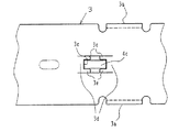
図1〜図3は発明の実施の形態1を示し、図1はシューリム3とシューウェブ4の突起溶接前の状態を示す正面図、図2は図1の周方向の位置決め部を示す拡大図、図3は図2の平面図である。
【0014】
幅方向の両側にビード部3aが、また幅方向の中心線上に複数の溶接突起3bが形成されたシューリム3には、幅方向の中心線上の所定の位置に周方向に間隔を隔てて対向する掛かり代増大用の突起3dが前記溶接突起3bと同方向に、かつ同高さにプレスによる切り出し成形で一体に突設されている。これにより、対向する掛かり代増大用の突起3d間で周方向の位置決め用の穴3cが形成される。また、前記掛かり代増大用の突起3dの高さを溶接突起3bの高さに合わせることは必須でなく、多少の高低差は有ってもよい。要はシューリム3の板厚や溶接突起3bの高さを勘案して最適高さを決定すればよい。
尚、図3において、前記した対向する掛かり代増大用の突起3dが形成する位置決め用の穴3cの幅方向両側には、夫々左右の掛かり代増大用の突起3dが接近する方向に突設部3eが形成されている。
【0015】
4はシューウェブで、前記した従来のシューウェブ4と同形状をしており、その位置決め用の突起4cの高さはシューリム3の板厚より若干低く設定されている。
【0016】
前記した構成によれば、図1および図2に示す突起溶接前の状態図から明らかなように、シューウェブ4の外周面上にシューリム3の溶接突起3bを載置したとき、シューウェブ4の位置決め用の突起4cがシューリム3の位置決め用の穴3cに嵌入する掛かり代は、シューリム3の溶接突起3bの高さだけ大きくなり、前記位置決め用の突起4cの先端がシューリム3表面近くまで達するから、従来に比べて格段に掛かり代が増大する。
尚、突起溶接については従来と同じであるから、その説明は以降についても省略する。
【0017】
従って、作業者が前方から位置決め用の突起4c先端を目視確認して作業できるし、或いは、シューリム3を左右に僅かに動かして見るだけでその位置決め用の穴3cがシューウェブ4の位置決め用の突起4cに嵌合しているか否か、感覚的な判断が極めて明確となって作業性が向上すると共に、誤作業を完全に防止し得る。
また、掛かり代増大用の突起3dや位置決め用の穴3cの形成は、溶接突起3bの突起出しやパイロット用の穴(図示せず)明けと同時にプレス成形できるから、その加工も簡単である。しかもシューリム3のR曲げ加工時に内Rが多少小さくなってもシューウェブ4の位置決め用の突起4cとシューリム3の位置決め用の穴3cの掛かり代を確保できるから、この加工も簡単になるし、上下電極に多少の芯ずれが生じてもシューリム3の周方向ずれの心配はない。
尚、突起溶接時に掛かり代増大用の突起3dも溶接されることから、全体の溶接強度が向上するし、また本来の溶接突起3bの点数削減を図ることも可能である。
更に、シューリム3に形成した突設部3eにより、シューウェブ4に対するシューリム3の幅方向のずれを制限し得るため、従来、溶接治具に設置していたシューリム3の幅方向のずれ防止手段に係わる構造を簡略化できるという利点もある。
【0018】
図4および図5は、発明の実施の形態2を示し、シューリムに形成した位置決め用の突起の変形例である。図4はシューリム3とシューウェブ4の突起溶接前における周方向の位置決め部を示す拡大図、図5は図4の平面図である。
【0019】
シューリム3には、プレスによる突起出し成形で円形の掛かり代増大用の突起3dが形成されると共に、該掛かり代増大用の突起3d内に、シューリム3の周方向に長い形状をした矩形の位置決め用の穴3cが穿設されている。尚、掛かり代増大用の突起3dの形状が円形に限定されるものでは決してない。
この位置決め用の穴3cにシューウェブ4の位置決め用の突起4cを嵌合させた状態は、前記した発明の実施の形態1と同じであって、その作用効果も全く同じであるから説明を省略する。
【0020】
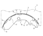
図6および図7は発明の実施の形態3を示し、図6はシューリム3とシューウェブ4の突起溶接前の状態を示す正面図、図7は図6の周方向の位置決め部を示す拡大図である。
【0021】
本実施の形態3は、前記した実施の形態1および2に対してシューウェブ4及びシューリム3の外形状が異なる。
すなわち、シューウェブ4にはその外周面の位置決め用の突起4c両側に窪み4dが形成され、この窪み4dにシューリム3に形成した掛かり代増大用の突起3dが没入するように形成されている。これによって、両者3と4の周方向の位置合せ時に、シューウェブ4の位置決め用の突起4c先端をシューリム3の表面から突出させることができる。
また、前記した発明の実施の形態1および2におけるシューリム3に形成した溶接突起3bに代えて、シューウェブ4の外周に複数の溶接突起4bを形成しているが、何れの部品に形成してもよいことは明白である。
【0022】
前記したように、シューリム3をシューウェブ4の溶接突起4b上に載置した状態で、シューウェブ4の位置決め用の突起4c先端をシューリム3の表面から突出するように成したから、位置合せ作業時の視認効果および溶接時の位置ずれ防止効果が一層向上する。
【0023】
【発明の効果】
本発明は、以上説明したようになるからつぎのような効果を得ることができる。
【0024】
<イ> シューリムに形成された位置決め用の穴部をシューウェブの外周に向けて突設し、シューウェブに形成された位置決め用の突起との掛かり代が増大するようにしたから、目視確認或いは両者の嵌合感覚が明確となり作業性が大幅に向上すると共に、誤作業を完全に払拭できる。
<ロ> 位置決め用の穴と位置決め用の突起との掛かり代が大きいから、シューリムの内Rが多少小さく形成された場合や上下部電極に多少の芯ずれが生じた場合においても、シューリムの周方向ずれの心配がなくなって、良品の選別をせずに済むし、廃品が発生しないから非常に経済的である。
<ハ> シューリムに形成された位置決め用の突起を溶接突起に活用し得るから、全体の溶接強度を向上させることができる。
<ニ> シューリムに形成された周方向位置決め用の突起部に、シューウェブに対するシューリムの幅方向ずれを制限する手段を形成することにより、溶接治具構造を簡略化できる。
<ホ> シューリムに形成する位置決め用の突起や穴、およびシューウェブに形成する位置決め用の突起や窪みの成形は、全て従来のプレス順送成形に組込めるからその加工が簡単である。
【図面の簡単な説明】
【図1】 発明の実施の形態1に係る突起溶接前のシューリムとシューウェブの状態を示す正面図。
【図2】 図1の周方向位置決め部を示す拡大図。
【図3】 図2の平面図。
【図4】 発明の実施の形態2に係る周方向位置決め部の突起溶接前の状態を示す拡大正面図。
【図5】 図4の平面図。
【図6】 発明の実施の形態3に係る突起溶接前のシューリムとシューウェブの状態を示す正面図。
【図7】 図6の周方向位置決め部を示す拡大図。
【図8】 従来のシューリムとシューウェブの突起溶接前の状態を示す正面図。
【図9】 図8のシューリムの位置決め部を示す拡大平面図。
【図10】 図8のシューリムの位置決め部の変形例を示す平面図。
【図11】 従来のブレーキシューの正面図。
【符号の説明】
2 ブレーキシュー
3 シューリム
3b 溶接突起
3c 位置決め用の穴
3d 掛かり代増大用の突起
3e 突設部
4 シューウェブ
4b 溶接突起
4c 位置決め用の突起
4d 窪み
5 ブレーキライニング
6 上部電極[0001]
BACKGROUND OF THE INVENTION
The present invention relates to a brake shoe for a drum brake, and more particularly to a positioning structure for a shoe rim and a shoe web at the time of projection welding.
[0002]
[Prior art]
A brake shoe for this kind of drum brake is usually configured as shown in FIGS. FIG. 8 is a state diagram before the projection welding of the
[0003]
The substantially crescent-
Usually, both the
[0004]
As shown in FIG. 8, the projection welding of the
[0005]
[Problems to be solved by the invention]
The above-described brake shoes for drum brakes have the following problems.
[0006]
<A> If the
However, since the
<B> In particular, if there is any misalignment between the lower electrode and the
<C> also possible to completely eliminate the deviation of the
[0007]
The present invention has been made to solve the above-described problems, and an object of the present invention is to make it easy to position a shoe rim at the time of brake shoe projection welding and to prevent the occurrence of circumferential displacement. It is to provide an excellent brake shoe.
[0008]
[Means for Solving the Problems]
The invention according to claim 1, a shoe rim of the brake lining is fixed to the outer peripheral surface, the brake shoes of the drum brake comprising a shoe webs are integrated by a plurality of projections welded to the inner circumferential surface of the shoe rim, A positioning hole drilled in the shoe rim, and a protrusion for increasing the allowance, which is arranged facing the circumferential direction by causing the peripheral edge of the positioning hole to protrude toward the outer peripheral surface of the shoe web. A brake shoe for a drum brake, characterized in that a positioning projection formed on the shoe web and entering the positioning hole between the projections for increasing the hook allowance is provided .
[0009]
According to a second aspect of the present invention, in the first aspect, the protruding portions are formed on both sides in the direction orthogonal to the circumferential direction of the protrusion for increasing the hooking allowance to limit the displacement in the width direction of the shoe rim with respect to the shoe web. A brake shoe for a drum brake, characterized in that it is configured as described above .
[0010]
According to a third aspect of the present invention, in the first aspect, a recess is formed on both sides in the circumferential direction of the positioning projection formed on the shoe web, and the projection for increasing the allowance is immersed in the recess. This is a brake shoe for drum brakes.
[0011]
According to a fourth aspect of the present invention, in any one of the first to third aspects, at the time of the projection welding of the shoe rim and the shoe web, the projection for increasing the allowance protruding from the shoe rim is welded simultaneously. and wherein, is a brake shoe for a drum brake.
[0012]
DETAILED DESCRIPTION OF THE INVENTION
Hereinafter, embodiments of the present invention will be described with reference to FIGS.
In addition, the same components and parts as those of the above-described prerequisite technology (FIGS. 8 to 11) of the present invention are denoted by the same reference numerals, and detailed description thereof is omitted.
[0013]
1 to 3 show a first embodiment of the present invention, FIG. 1 is a front view showing a state before projection welding of a
[0014]
A
In FIG. 3, projecting portions are provided on both sides in the width direction of the
[0015]
A
[0016]
According to the configuration described above, when the
In addition, since protrusion welding is the same as before, the description thereof will be omitted in the following.
[0017]
Accordingly, the operator can visually check the front end of the
In addition, the formation of the
In addition, since the
Furthermore, since the protruding portion 3e formed on the
[0018]
4 and 5 show a second embodiment of the present invention, which is a modification of the positioning protrusion formed on the shoe rim. 4 is an enlarged view showing a positioning portion in the circumferential direction before the projection welding of the
[0019]
The
The state in which the
[0020]
6 and 7 show a third embodiment of the invention, FIG. 6 is a front view showing a state before the projection welding of the
[0021]
The third embodiment is different from the first and second embodiments in the outer shape of the
That is, the
Further, in place of the
[0022]
As described above, since the tip of the
[0023]
【The invention's effect】
Since the present invention has been described above, the following effects can be obtained.
[0024]
<A> Since the positioning hole formed in the shoe rim protrudes toward the outer periphery of the shoe web so that the margin for the positioning projection formed in the shoe web increases, The sense of fitting between the two becomes clear and the workability is greatly improved, and erroneous work can be completely eliminated.
<B> Since the allowance between the positioning hole and the positioning projection is large, the circumference of the shoe rim can be improved even when the inner radius R of the shoe rim is slightly small or the upper and lower electrodes are slightly misaligned. It is very economical because there is no need to worry about direction deviation, and there is no need to sort out good products.
<C> Since the positioning projections formed on the shoe rim can be used as welding projections, the overall welding strength can be improved.
<D> By forming a means for limiting the displacement in the width direction of the shoe rim with respect to the shoe web in the circumferential positioning protrusion formed on the shoe rim, the welding jig structure can be simplified.
<E> The positioning projections and holes formed on the shoe rim and the positioning projections and depressions formed on the shoe web can all be incorporated into the conventional press progressive molding, and the processing is simple.
[Brief description of the drawings]
FIG. 1 is a front view showing a state of a shoe rim and a shoe web before projection welding according to a first embodiment of the invention.
FIG. 2 is an enlarged view showing a circumferential positioning portion in FIG. 1;
FIG. 3 is a plan view of FIG. 2;
FIG. 4 is an enlarged front view showing a state of the circumferential positioning portion according to the second embodiment of the present invention before projection welding.
FIG. 5 is a plan view of FIG. 4;
FIG. 6 is a front view showing a state of a shoe rim and a shoe web before projection welding according to a third embodiment of the invention.
7 is an enlarged view showing a circumferential positioning portion of FIG. 6;
FIG. 8 is a front view showing a state before the projection welding of a conventional shoe rim and shoe web.
9 is an enlarged plan view showing a positioning part of the shoe rim of FIG. 8. FIG.
FIG. 10 is a plan view showing a modification of the positioning part of the shoe rim of FIG.
FIG. 11 is a front view of a conventional brake shoe.
[Explanation of symbols]
2 Brake shoes
3 Shoe Rim
3b Weld protrusion
3c Positioning hole
Protrusions for increasing 3d allowance
3e Projection
4 Shoeweb
4b Welding protrusion
4c Protrusion for positioning
4d hollow
5 Brake lining
6 Upper electrode
Claims (4)
前記シューリムに穿設された位置決め用の穴と、該位置決め用の穴の周縁部を前記シューウェブの外周面に向けて突出させ、周方向に対向して配置された掛り代増大用の突起と、前記シューウェブに形成され、前記掛かり代増大用の突起間の前記位置決め用の穴に進入する位置決め用の突起とを設けたことを特徴とする、
ドラムブレーキ用のブレーキシュー。A shoe rim of the brake lining on the outer circumferential surface is fixed, the brake shoes of the drum brake comprising a shoe webs are integrated by a plurality of projections welded to the inner circumferential surface of the shoe rim,
A positioning hole drilled in the shoe rim, and a protrusion for increasing the allowance, which is arranged facing the circumferential direction by causing the peripheral edge of the positioning hole to protrude toward the outer peripheral surface of the shoe web. A positioning protrusion formed on the shoe web and entering the positioning hole between the protrusions for increasing the allowance ;
Brake shoes for drum brakes.
ドラムブレーキ用のブレーキシュー。In Claim 1, The protrusion part was formed in the both sides of the direction orthogonal to the circumferential direction of the protrusion for the said hook allowance increase, and the width direction shift | offset | difference of the shoe rim with respect to the said shoe web was restrict | limited. ,
Brake shoes for drum brakes.
ドラムブレーキ用のブレーキシュー。In Claim 1, a depression is formed on both sides in the circumferential direction of the positioning projection formed on the shoe web, and the projection for increasing the allowance is immersed in the depression .
Brake shoes for drum brakes.
ドラムブレーキ用のブレーキシュー。In any one of Claim 1 thru | or 3, the protrusion for the circumferential direction hook allowance protrudingly provided in the said shoe rim at the time of the projection welding of the said shoe rim and a shoe web is welded simultaneously .
Brake shoes for drum brakes.
Priority Applications (1)
| Application Number | Priority Date | Filing Date | Title |
|---|---|---|---|
| JP13262198A JP4020487B2 (en) | 1998-04-28 | 1998-04-28 | Brake shoe for drum brake |
Applications Claiming Priority (1)
| Application Number | Priority Date | Filing Date | Title |
|---|---|---|---|
| JP13262198A JP4020487B2 (en) | 1998-04-28 | 1998-04-28 | Brake shoe for drum brake |
Publications (2)
| Publication Number | Publication Date |
|---|---|
| JPH11311271A JPH11311271A (en) | 1999-11-09 |
| JP4020487B2 true JP4020487B2 (en) | 2007-12-12 |
Family
ID=15085616
Family Applications (1)
| Application Number | Title | Priority Date | Filing Date |
|---|---|---|---|
| JP13262198A Expired - Lifetime JP4020487B2 (en) | 1998-04-28 | 1998-04-28 | Brake shoe for drum brake |
Country Status (1)
| Country | Link |
|---|---|
| JP (1) | JP4020487B2 (en) |
Families Citing this family (3)
| Publication number | Priority date | Publication date | Assignee | Title |
|---|---|---|---|---|
| JP4544097B2 (en) * | 2005-08-25 | 2010-09-15 | 株式会社アドヴィックス | Brake shoe for drum brake |
| KR101073884B1 (en) * | 2011-04-08 | 2011-10-17 | (주)삼성정밀 | Brake shoe and manufacturing method thereof |
| CN109958726B (en) * | 2017-12-25 | 2020-09-18 | 陕西汉德车桥有限公司 | Drum type single-pin brake |
-
1998
- 1998-04-28 JP JP13262198A patent/JP4020487B2/en not_active Expired - Lifetime
Also Published As
| Publication number | Publication date |
|---|---|
| JPH11311271A (en) | 1999-11-09 |
Similar Documents
| Publication | Publication Date | Title |
|---|---|---|
| US5786651A (en) | Stator core having a plurality of connected circumferentially segmented cores and method and apparatus for assembling same | |
| JP2552633Y2 (en) | Disc brake | |
| JP4020487B2 (en) | Brake shoe for drum brake | |
| EP0937906A2 (en) | A wear detection probe for a brake pad | |
| JP2516998Y2 (en) | Wheel cover | |
| EP2942145B1 (en) | Electrode removing device for spot welding | |
| JPH07151171A (en) | Disk brake | |
| JPS5925893B2 (en) | Vehicle disc brake friction pad | |
| JPH0353062Y2 (en) | ||
| JP2000257648A (en) | Clutch drum structure | |
| JP2556682Y2 (en) | Disc brake | |
| JPH0357350Y2 (en) | ||
| EP4428388A1 (en) | Air disc brake pad | |
| JP4021040B2 (en) | Drum brake device with wear indicator | |
| JP3721548B2 (en) | Punch retainer for press | |
| GB2332728A (en) | Eccentric vibration isolator | |
| JP2543712Y2 (en) | Drum brake shoe hold-down device | |
| JPS6023562Y2 (en) | Shu hold down spring | |
| JPH0354994Y2 (en) | ||
| JPH0749090Y2 (en) | Drum brake anchor device | |
| JPH0226770Y2 (en) | ||
| JPH08240234A (en) | Friction pad of disk brake | |
| JPS60488Y2 (en) | Synthetic resin snap spring | |
| JPH0353060Y2 (en) | ||
| JP3006335B2 (en) | Engine mount base structure |
Legal Events
| Date | Code | Title | Description |
|---|---|---|---|
| A521 | Written amendment |
Free format text: JAPANESE INTERMEDIATE CODE: A523 Effective date: 19980710 |
|
| A621 | Written request for application examination |
Free format text: JAPANESE INTERMEDIATE CODE: A621 Effective date: 20050316 |
|
| A521 | Written amendment |
Free format text: JAPANESE INTERMEDIATE CODE: A523 Effective date: 20050704 |
|
| A977 | Report on retrieval |
Free format text: JAPANESE INTERMEDIATE CODE: A971007 Effective date: 20070104 |
|
| A131 | Notification of reasons for refusal |
Free format text: JAPANESE INTERMEDIATE CODE: A131 Effective date: 20070521 |
|
| RD02 | Notification of acceptance of power of attorney |
Free format text: JAPANESE INTERMEDIATE CODE: A7422 Effective date: 20070713 |
|
| A521 | Written amendment |
Free format text: JAPANESE INTERMEDIATE CODE: A523 Effective date: 20070719 |
|
| TRDD | Decision of grant or rejection written | ||
| A01 | Written decision to grant a patent or to grant a registration (utility model) |
Free format text: JAPANESE INTERMEDIATE CODE: A01 Effective date: 20070904 |
|
| A61 | First payment of annual fees (during grant procedure) |
Free format text: JAPANESE INTERMEDIATE CODE: A61 Effective date: 20070925 |
|
| FPAY | Renewal fee payment (event date is renewal date of database) |
Free format text: PAYMENT UNTIL: 20101005 Year of fee payment: 3 |
|
| R150 | Certificate of patent or registration of utility model |
Free format text: JAPANESE INTERMEDIATE CODE: R150 |
|
| FPAY | Renewal fee payment (event date is renewal date of database) |
Free format text: PAYMENT UNTIL: 20101005 Year of fee payment: 3 |
|
| S533 | Written request for registration of change of name |
Free format text: JAPANESE INTERMEDIATE CODE: R313533 |
|
| FPAY | Renewal fee payment (event date is renewal date of database) |
Free format text: PAYMENT UNTIL: 20101005 Year of fee payment: 3 |
|
| R350 | Written notification of registration of transfer |
Free format text: JAPANESE INTERMEDIATE CODE: R350 |
|
| FPAY | Renewal fee payment (event date is renewal date of database) |
Free format text: PAYMENT UNTIL: 20101005 Year of fee payment: 3 |
|
| FPAY | Renewal fee payment (event date is renewal date of database) |
Free format text: PAYMENT UNTIL: 20101005 Year of fee payment: 3 |
|
| FPAY | Renewal fee payment (event date is renewal date of database) |
Free format text: PAYMENT UNTIL: 20111005 Year of fee payment: 4 |
|
| FPAY | Renewal fee payment (event date is renewal date of database) |
Free format text: PAYMENT UNTIL: 20111005 Year of fee payment: 4 |
|
| FPAY | Renewal fee payment (event date is renewal date of database) |
Free format text: PAYMENT UNTIL: 20121005 Year of fee payment: 5 |
|
| FPAY | Renewal fee payment (event date is renewal date of database) |
Free format text: PAYMENT UNTIL: 20121005 Year of fee payment: 5 |
|
| FPAY | Renewal fee payment (event date is renewal date of database) |
Free format text: PAYMENT UNTIL: 20121005 Year of fee payment: 5 |
|
| FPAY | Renewal fee payment (event date is renewal date of database) |
Free format text: PAYMENT UNTIL: 20131005 Year of fee payment: 6 |
|
| R250 | Receipt of annual fees |
Free format text: JAPANESE INTERMEDIATE CODE: R250 |
|
| R250 | Receipt of annual fees |
Free format text: JAPANESE INTERMEDIATE CODE: R250 |
|
| R250 | Receipt of annual fees |
Free format text: JAPANESE INTERMEDIATE CODE: R250 |
|
| R250 | Receipt of annual fees |
Free format text: JAPANESE INTERMEDIATE CODE: R250 |
|
| R250 | Receipt of annual fees |
Free format text: JAPANESE INTERMEDIATE CODE: R250 |
|
| S111 | Request for change of ownership or part of ownership |
Free format text: JAPANESE INTERMEDIATE CODE: R313113 |
|
| R350 | Written notification of registration of transfer |
Free format text: JAPANESE INTERMEDIATE CODE: R350 |
|
| EXPY | Cancellation because of completion of term |