JP4016830B2 - Planar heating element for snow melting equipment - Google Patents
Planar heating element for snow melting equipment Download PDFInfo
- Publication number
- JP4016830B2 JP4016830B2 JP2002372236A JP2002372236A JP4016830B2 JP 4016830 B2 JP4016830 B2 JP 4016830B2 JP 2002372236 A JP2002372236 A JP 2002372236A JP 2002372236 A JP2002372236 A JP 2002372236A JP 4016830 B2 JP4016830 B2 JP 4016830B2
- Authority
- JP
- Japan
- Prior art keywords
- snow melting
- heating element
- snow
- heating means
- surface plate
- Prior art date
- Legal status (The legal status is an assumption and is not a legal conclusion. Google has not performed a legal analysis and makes no representation as to the accuracy of the status listed.)
- Expired - Fee Related
Links
Images


Description
【0001】
【発明の属する技術分野】
本発明は、主として降雪地域で用いられる融雪装置用の面状発熱体に関するもので、一般家庭や店舗の敷地内の雪を効率的に融雪するようにしたものである。
【0002】
【従来の技術】
従来、積雪の多い寒冷地においては、公共の道路はもとより、一般家庭や店舗の敷地の、特に歩道から一般家庭の玄関、車庫あるいは駐車スペースまでのアプローチの除雪作業が、積雪期の日常生活での大きな問題とされてきている。
【0003】
これを解決するためのものとしては、発熱体として電熱線や温水パイプ等を敷地内の地面に埋設して、路面の加熱を行うことで融雪を行う融雪装置がある。電熱線は通電することでジュール熱によって発熱するものであり、温水パイプは灯油ボイラーの燃焼で加熱した温水(実際は不凍液)を熱媒として循環することで発熱するものである。これらの加熱によって路面温度を上昇させて、路面上の雪を融雪することが一般的である(例えば、特許文献1参照)。このような融雪装置は、ロードヒーティング装置、あるいはロードヒーティングとも呼ばれる。
【0004】
図7に具体例を示したように、発熱体としての電熱線30は、路床部31の上面に金属メッシュとともに敷設されて、コンクリート路盤部32、アスファルト舗装部33にて埋設されている。もちろん、電熱線30の位置に温水パイプを埋設したものもあるが、その埋設部の基本的な構成は同様である。
【0005】
このような融雪装置34は、降雪35を検知するために、降雪センサー、気温センサー、地温センサー、水分センサー(センサー類の図示は省略)を備えて、各センサーからの信号に応じて自動運転を行なうか、あるいは使用者の判断で手動運転するための制御装置を備えている。
【0006】
また、玄関先や階段といった、主として人の通行が行われる場所には、単に置くだけでよいマット状の発熱体もある(例えば、特許文献2参照)。これは一般には、加熱手段をその内部に一体に成形したゴムシート状クッション材であって、降雪時に通電すれば、比較的速やかに表面の雪を融雪できるものである。このようなものは融雪マットあるいは発熱マットとも呼ばれる。
【0007】
【特許文献1】
特開平11−336038号公報
【特許文献2】
実開平02−10829号公報
【0008】
【発明が解決しようとする課題】
しかしながら、従来の埋設方式の場合、発熱体である電熱線30や温水パイプを地表から約100mmの地中に埋設しているので、降雪35をセンサーが検知して、ただちに自動運転を開始、または手動による運転を開始しても、しばらくの間は、発熱体である電熱線30はその上部の地面を加熱することで、融雪装置34全体の温度を上昇させるために、運転時間と電気エネルギーを必要として、降雪35によって地表に堆積する雪をただちに融雪するには至らない。このように、融雪までに時間がかかる。
【0009】
また、降雪35は、通常、24時間連続的に発生することは少なくて、間欠的に降雪することが多い。したがって、融雪装置34の運転も、間欠的であることが多くて、その都度、低温度の外気によって、融雪装置34の温度は低下する。そこで、次回の降雪時には、一度冷却した路面全体を再度加温するために時間が必要である。このような原因によっても、電気あるいは灯油の消費量が多くなるので、ランニングコストが高くなる。
【0010】
このように、埋設型の融雪装置34は、駐車スペースに設置するのに耐久的に十分な構造であるが、その融雪性能は、積雪期全体を通じて考えると、融雪装置34自体の温度上昇のために使用されるエネルギーの割合が大きく、また間欠的な運転によるエネルギーの損失も大きい。また、土木工事によって、地中に発熱体を埋設する融雪装置の場合、その施工には長時間の工期が必要で、そのための工事費も高い。
【0011】
一方、複数の融雪マットを設置するものでは、加熱手段に融雪用熱量を供給するには、2つの手段がある。第1の手段は、各々の融雪マットに、融雪用熱量を供給する電線を設け、直接、融雪用熱量を供給するものである。この場合、結線作業を一ヵ所で行うことも可能であるが、供給電線が多くなり、その収納が複雑になる。第2の手段としては、面状発熱体の加熱手段同士を電気的に接続するものである。この場合、接続部を設けなければならず、その接続部は、絶縁防水構造にしなければならない。
【0012】
また、地表面に設置するので、表面プレートからの荷重が直接、接続部にかかるので、駐車スペースに設置する装置としては、耐久的に問題があるといえる。したがって、融雪マットは、駐車スペースに設置するには、耐久的に十分とはいえない。
【0013】
本発明は、前記従来の課題を解決するために、融雪用熱量を効果的に融雪に利用するとともに駐車スペースにも設置可能な融雪装置用の面状発熱体を提供することを目的としている。
【0014】
【課題を解決するための手段】
前記目的を達成するために、本発明の融雪装置用の面状発熱体は、加熱手段上に設けて加熱される表面プレートを、下面端縁部を支持する複数の枠部と、下面中央部を支持する複数の補強枠部とで支持するとともに、複数の枠部同士を連結する連結枠部を枠部に対して着脱自在とし、その下部に加熱手段への熱量供給経路を形成したものである。
【0015】
これにより、加熱手段への熱量供給経路に、直接、表面プレート上部から荷重がかかることがなく、また、加熱手段の設置時には、連結枠部を取り外せば簡単に施工できる。したがって、この面状発熱体は、融雪用熱量を効果的に融雪に利用するとともに駐車スペースにも設置可能となる。
【0016】
【発明の実施の形態】
請求項1に記載の発明は、融雪用熱量を供給する加熱手段と、この加熱手段上に設けて加熱される表面プレートと、表面プレートの下面端縁部を支持する複数の枠部と、この複数の枠部同士を連結する連結枠部と、表面プレートの下面中央部を支持する複数の補強枠部とを有し、前記連結枠部は枠部に対して着脱自在とするとともにその下部に加熱手段への熱量供給経路を形成した融雪装置用の面状発熱体とすることにより、加熱手段への熱量供給経路に、直接、表面プレート上部から荷重がかかることがなく、また、加熱手段の設置時には、連結枠部を取り外せば簡単に施工できる。したがって、この面状発熱体は、融雪用熱量を効果的に融雪に利用するとともに駐車スペースにも設置可能となる。
【0017】
請求項2に記載の発明は、連結枠部はその片側の端部に、隣接する他の面状発熱体の枠部間を連結する複数の嵌合部を有し、他側の端部には、少なくとも一つの嵌合部を有する請求項1に記載の融雪装置用の面状発熱体とすることにより、隣接する面状発熱体の枠部を含む少なくとも3ヶ所の枠部を連結でき、面状発熱体にかかる水平方向の荷重に対しても強度を有するものである。
【0018】
請求項3に記載の発明は、連結枠部に保護部材を設けた請求項1または2に記載の融雪装置用の面状発熱体とすることにより、施工時、枠部端面で加熱手段や供給用電線を傷つけることなく、簡単に施工できるものである。
【0019】
請求項4に記載の発明は、複数の面状発熱体間の加熱手段を電気的に接続する絶縁防水部を連結枠部の熱量供給経路に設けた請求項1〜3のいずれか1項に記載の融雪装置用の面状発熱体とすることにより、表面プレート上面からの荷重に対して絶縁防水部を保護でき、駐車スペースに設置できることで、効率よく熱量を融雪に利用できるものである。
【0020】
請求項5に記載の発明は、絶縁防水部を保護部材に内装した請求項4に記載の融雪装置用の面状発熱体とすることにより、面状発熱体を構成する部材の端面で、絶縁防水部を傷つけることがなく、駐車スペースに設置できる強度を保持するものである。
【0021】
【実施例】
以下、本発明の実施例について、図面を参照しつつ説明する。
【0022】
(実施例1)
図1〜図5は本発明の実施例1における融雪装置用の面状発熱体を示すものである。
【0023】
本実施例においては、図1に示すように、面状発熱体1を、路盤部3上の舗装部2の上面に複数枚設置して、降雪4を融雪する融雪装置5とするものであって、降雪地域の家庭や店舗において、歩道から玄関及び駐車スペースに至るアプローチを含めた融雪装置敷設部を形成するものである。この融雪装置は、降雪4を検知する降雪センサー、気温センサー、地温センサー(センサー類の図示は省略)を備えて、センサーからの信号に応じて自動運転する、あるいは使用者の判断で手動運転するための制御装置6を備えている。
【0024】
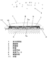
次に、図2〜図4に基づいて一つの面状発熱体1の内部構成を説明する。7は加熱手段であって、通電することで発熱する電熱線7aを所定の間隔で支持板7b上に設けて構成している。支持板7bには複数の嵌合孔7cが設けられている。8は加熱手段7により加熱され発熱する金属等の材料よりなる表面プレートで、加熱手段7の上部に配置されている。表面プレート8上には、塗料や、シートまた凹凸等を設けて、滑り止め処理を施している。9は複数の突部9aで表面プレート8を支持し、加熱手段7を保護している複数の補強枠部で、表面プレート9の中央部下部に位置し、面状発熱体1にかかる荷重を支えている。複数の突部9aは支持板7bの嵌合孔7cを通して、表面プレート9の中央部下部を支えているものである。10、11は補強枠部9と同様に表面プレート8の下部に位置し、全周の端縁部を支持する複数の枠部で、枠部11には表面プレート8を固定するための雌ネジ部等の固定部11aを有している。
【0025】
なお、枠部10にも同様な固定部を設けるようにしてもよい。補強枠部9と枠部10は、爪と係合孔等で互いに係合している。12は片側の端部に、隣接する他の面状発熱体の枠部11、11間を連結する複数の嵌合部14を有し、他側の端部には、枠部10を連結する少なくとも一つの嵌合部15を有する連結枠部で、その下部には、加熱手段7への融雪用熱量を供給する熱量供給経路13が形成されている。嵌合部14、15は相手の係合孔に嵌合する爪等よりなっている。そして、この連結枠部12はステンレスや防錆塗装等を施した防錆材料で構成されている。15は表面プレート8を枠部11に固定する固定ボルトで、固定部11aにネジ込んでいる。これも連結枠部12と同様、ステンレスや防錆塗装等を施した防錆材料で構成されている。
【0026】
次に、融雪装置5の施工方法及び運転方法ついて説明する。施工者は、ある程度平面な設置面に、枠部10、11を仮置きする。次に、隣接する枠部10に補強枠部9を爪と係合孔等で係合固定する。次に、加熱手段7をその嵌合孔7cと補強枠部9の突部9aで位置決めし、水平方向に固定するものである。その状態で、融雪用熱量を供給する熱量供給電線と加熱手段7を接続する、または、複数の加熱手段7を接続するものである。
【0027】
融雪熱量供給電線及び加熱手段7は、枠部10、枠部11内部の空間を通過させ、その上から連結枠部12を枠部10、11に嵌合させて、熱量供給経路13を保護するとともに、枠部10、11を連結させる。連結枠部12の高さは、嵌合した状態では、枠部10、11より低く設計されている。次に、表面プレート8を上部から設置し、枠部10、11によりその端縁部が、また、補強枠部9で中央部が支持されるので、加熱手段7に表面プレート8からの荷重が直接かからなくなっている。最後に、枠部11に設けられた固定部11aに固定ボルト15施すことにより表面プレート8を固定する。
【0028】
また、図示していないが、サーミスタ等の温度検知手段を表面プレート8の下部に設け、バネ材等で表面プレート下部に温度検知手段を附勢しているものである。
【0029】
次に、運転方法について説明する。分かりやすくするために、使用者自身で降雪4があることを判断して、運転を開始した場合を想定する。制御装置6は加熱手段7に通電を開始して表面プレート8を加熱する。この表面プレート8の熱容量は小さく、且つ舗装部2の表面に設置されているので、所定の消費電力量にて、短時間で表面プレート8の温度が上昇する。引き続いて供給される熱量は、降雪4が面状発熱体1の表面に堆積するとすぐに、これを融雪水にするための融解熱として使用されて、短時間で融雪が行われる。
【0030】
また、使用者は降雪4が停止したと判断すれば、直ちに運転を停止すれば良いものである。もちろん、センサーの信号に基づいて自動運転もできる。いずれにせよ、従来の埋設型の融雪装置に比べて、短時間で融雪することができ、したがって少ない消費電力量で融雪ができる。
【0031】
また、実際の降雪4は、24時間連続的に発生することは少なくて、夜間から早朝にかけて間欠的に降って、かつ日中は降らないといったように、間欠的に降雪することが多い。すなわち、融雪装置5の運転も間欠的であることが多くなる。
【0032】
したがって、その都度、面状発熱体1は一度冷却されるものの、再度の加温は短時間で行える。そのためにも、面状発熱体1の消費電力量が少なくても良く、融雪装置5のランニングコストも安価である。
【0033】
以上のように、本実施例においては、表面プレート8を地表面に設置できるため、熱量を有効に表面プレート8上の積雪や降雪に与えることができる。更に、熱量供給経路13に加熱手段7や供給電線を配してから連結枠部12を嵌合できるので、施工が簡単になるものである。
【0034】
したがって、降雪時に加熱手段7に通電すれば、上部の表面プレート8に融雪用熱量が供給され、表面プレート8の温度が速やかに上昇し、融雪効果を発揮するので、短時間に融雪が行えるものである。
【0035】
なお、本実施例では、加熱手段7が電熱線や温水パイプの場合には、加熱手段7は、表面プレート8に接触した状態である。加熱手段7を直接表面プレート8にテープや接着剤でつけても良い。テープや接着剤は、防水タイプのものであるのは言うまでもない。また、対候性のあるPPやPE等の樹脂等に張り付けたり、成形しての電線の装着溝を作り、装着させてもよい。
【0036】
なおまた、加熱手段7に高周波電流を通電して、金属製の表面プレート8を誘導加熱して発熱体としても良い。この場合、磁性体の表面プレート8を直接的に誘導加熱で発熱させるので、きわめて高速に面状発熱体1の表面温度を上昇させて、短時間で融雪することができるものである。もちろん、誘導加熱であるので、表面プレート8と加熱手段7の間に空隙や部材が存在しても、つまり表面プレート8と加熱手段7が密着していなくても、表面プレート8を直接加熱できることは言うまでもない。
【0037】
また、連結枠部12はその片側の端部に複数の嵌合部14と、一方の端部にも嵌合部15とを有した構成であるため、隣接する面状発熱体1との共用部材にすると、隣接する面状発熱体1の枠部11間と枠部10との3ヶ所で連結でき、複数の面状発熱体1が一体化され、面状発熱体1にかかる水平方向の荷重に対しても強度を有するものである。また、加熱手段7設置時には、連結枠部12を取り外せばよく、簡単に施工できる。駐車スペースに設置でき、効率よく融雪を行うことができる。
【0038】
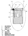
また、図5に示したように、連結枠部12に保護部材16を設けているものである。保護部材16は、ゴムやエラストマー等の弾性体や、樹脂製のもので、連結枠部12を覆う構成となっている。面状発熱体1の上部からの荷重に対して、表面プレート8及び連結枠部12が弾性変形しても、保護部材16が連結枠部12を内包しているので加熱手段7や熱量供給電線を保護することができる。また、施工時にも、枠部端面による破損を防ぐことができる。いずれにせよ、車等に対する強度を持ち、施工も簡単である面状発熱体1は、地表面に設置でき、効果的に融雪できる構成になっている。
【0039】
(実施例2)
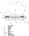
次に、図6は本発明の実施例2における融雪装置用の面状発熱体を示すものである。基本構成は実施例1と同様であり、同一要素には同一符号を付して説明を省略する。
【0040】
本実施例は、図に示すように、複数の加熱手段7を電気的に接続する絶縁防水部17を有し、この絶縁防水部17が連結枠部12の下部に固定されて設けられている点で、実施例1と異なる。
【0041】
複数の面状発熱体1の加熱手段7を電気的に接続する絶縁防水部17は、加熱手段7同士、もしくは、加熱手段7と融雪熱量供給電線18とを圧着端子等で接続し、その接続部を絶縁防水して内装しているものである。この絶縁防水部17を有しているので、複数の加熱手段7を連結でき、駐車スペース等の広範囲な設置面に対しても、融雪エネルギーを供給できるものである。
【0042】
絶縁防水部17は、シリコン等で接続部を固めてから、ブチルテープで分厚く巻き付けてもよいし、凹部に絶縁防水部17を固定した後、ウレタン系等のポッティング材を使用してよい。また、複数の加熱手段7を接続したかしめ部をケースに内装し、加熱手段7の電線部はゴム状の弾性体で締め付け、ケースの中には外部から水分が侵入しないようにし、更に、ゴムをケース端面に押し付けるようにケースの蓋をするようにしてもよい。
【0043】
連結枠部12には、面状発熱体1の外部へ加熱手段7及び融雪熱量供給電線18が通過する熱量供給経路13を有しており、この経路13に、絶縁防水部17を担時する固定部を有することで、絶縁防水部17は、表面プレート8と連結枠部12により保護される。更に、絶縁防水部17の位置決めが容易になり、施工が簡単になるものである。
【0044】
また、絶縁防水部17を保護部材に内装した構成としてもよい。保護部材は、あらかじめ、樹脂製の保護チューブ等を、1つの加熱手段7側に差し込んでおき、加熱手段7同士もしくは、加熱手段7と融雪熱量供給電線18を接続し、接続部を絶縁防水部17に内装した後、絶縁防水部17を保護してもよい。また、接続後、スパイラルチューブ等で絶縁防水部17の外部を保護してもよいものである。電線等の加熱手段7の破損を防ぐことができ、更に、絶縁防水部17に保護部材を設けることで、施工時にも、連結枠部12端面による破損を防ぐことができ、効率よく設置作業ができ、施工時間も短縮するものである。
【0045】
したがって、いずれにせよ絶縁防水部17が枠部10、11と表面プレート8と連結枠部12により保護されているため、地表面に設置できる耐久強度を有し、表面プレート8の温度を速やかに上昇させて、少ない消費電力量で、優れた融雪性能を実現する融雪装置5とすることが可能である。
【0046】
【発明の効果】
以上のように、本発明の融雪装置用の面状発熱体は、加熱手段上に設けて加熱される表面プレートを、下面端縁部を支持する複数の枠部と、下面中央部を支持する複数の補強枠部とで支持するとともに、複数の枠部同士を連結する連結枠部を枠部に対して着脱自在とし、その下部に加熱手段への熱量供給経路を形成したものであり、加熱手段への熱量供給経路に、直接、表面プレート上部から荷重がかかることがなく、また、加熱手段の設置時には、連結枠部を取り外せば簡単に施工できる。したがって、この面状発熱体は、融雪用熱量を効果的に融雪に利用するとともに駐車スペースにも設置可能となる。
【図面の簡単な説明】
【図1】本発明の実施例1における融雪装置用の面状発熱体の斜視図
【図2】同面状発熱体の断面図
【図3】同面状発熱体の要部断面図
【図4】同面状発熱体の分解斜視図
【図5】(a)同面状発熱体に用いる連結枠部の平面図
(b)同面状発熱体に用いる連結枠部の側面図
【図6】本発明の実施例2における融雪装置用の面状発熱体を切欠いて示す平面図
【図7】従来の融雪装置の設置構造を示す要部断面図
【符号の説明】
1 面状発熱体
5 融雪装置
7 加熱手段
8 表面プレート
9 補強枠部
10、11 枠部
12 連結枠部
13 熱量供給経路
16 保護部材
17 絶縁防水部
18 融雪熱量供給電線[0001]
BACKGROUND OF THE INVENTION
The present invention relates to a planar heating element for a snow melting device mainly used in a snowfall region, and is intended to efficiently melt snow in a general household or store site.
[0002]
[Prior art]
Conventionally, in cold regions with a lot of snow, snow removal work on public roads as well as on general households and store sites, especially from the sidewalks to the entrances to general households, garages, and parking spaces, is a common part of daily life in the snowy season. It has been a big problem.
[0003]
In order to solve this problem, there is a snow melting device that melts snow by heating a road surface by burying a heating wire, a hot water pipe, or the like as a heating element on the ground in the site. The heating wire generates heat by Joule heat when energized, and the hot water pipe generates heat by circulating hot water (actually antifreeze) heated by combustion of a kerosene boiler as a heat medium. It is common to melt the snow on the road surface by raising the road surface temperature by these heating (see, for example, Patent Document 1). Such a snow melting device is also called a road heating device or a road heating.
[0004]
As shown in a specific example in FIG. 7, the
[0005]
Such a
[0006]
There are also mat-like heating elements that can be simply placed at places where people pass, such as entrances and stairs (see, for example, Patent Document 2). In general, this is a rubber sheet cushion material in which a heating means is integrally formed, and can melt snow on the surface relatively quickly if energized during snowfall. Such a thing is also called a snow melting mat or a heat generating mat.
[0007]
[Patent Document 1]
Japanese Patent Laid-Open No. 11-336038 [Patent Document 2]
Japanese Utility Model Publication No. 02-10829
[Problems to be solved by the invention]
However, in the case of the conventional burying method, the
[0009]
Further, the
[0010]
As described above, the buried
[0011]
On the other hand, in the case where a plurality of snow melting mats are installed, there are two means for supplying the heating means with the amount of heat for melting snow. The first means is to provide each of the snow melting mats with an electric wire for supplying the amount of heat for melting snow and directly supplying the amount of heat for melting snow. In this case, it is possible to carry out the wiring work in one place, but the number of supply wires increases and the storage becomes complicated. As a second means, the heating means of the planar heating elements are electrically connected to each other. In this case, a connection portion must be provided, and the connection portion must have an insulating waterproof structure.
[0012]
Moreover, since it installs in the ground surface, since the load from a surface plate applies directly to a connection part, it can be said that it has a problem durable as an apparatus installed in a parking space. Therefore, the snow melting mat is not durable enough to be installed in a parking space.
[0013]
SUMMARY OF THE INVENTION In order to solve the above-described conventional problems, an object of the present invention is to provide a planar heating element for a snow melting device that can effectively use the amount of heat for snow melting for snow melting and can also be installed in a parking space.
[0014]
[Means for Solving the Problems]
In order to achieve the above object, a planar heating element for a snow melting device according to the present invention comprises a heating plate provided with a surface plate to be heated, a plurality of frame portions for supporting lower surface edge portions, and a lower surface central portion. The connecting frame portion that connects the plurality of frame portions is detachable from the frame portion, and a heat amount supply path to the heating means is formed in the lower portion. is there.
[0015]
Thereby, a load is not directly applied to the heat quantity supply path to the heating means from the upper part of the surface plate, and when the heating means is installed, the construction can be easily performed by removing the connecting frame portion. Therefore, this planar heating element can be used in a parking space while effectively using the heat for melting snow for melting snow.
[0016]
DETAILED DESCRIPTION OF THE INVENTION
The invention according to
[0017]
In the invention according to
[0018]
According to a third aspect of the present invention, there is provided a sheet heating element for a snow melting device according to the first or second aspect in which a protective member is provided on the connecting frame portion, so that heating means and supply can be performed at the end surface of the frame portion during construction. It can be easily constructed without damaging the electric wires.
[0019]
According to a fourth aspect of the present invention, in any one of the first to third aspects, the insulating waterproof portion that electrically connects the heating means between the plurality of planar heating elements is provided in the heat amount supply path of the connecting frame portion. By using the planar heating element for the snow melting device described above, the insulating waterproof portion can be protected against the load from the upper surface of the surface plate, and can be installed in a parking space, so that heat can be efficiently used for melting snow.
[0020]
According to a fifth aspect of the present invention, there is provided an insulating waterproof portion provided in a protective member, wherein the sheet heating element for a snow melting device according to the fourth aspect is insulated by an end face of a member constituting the planar heating element. It does not damage the waterproof part and maintains the strength that can be installed in a parking space.
[0021]
【Example】
Embodiments of the present invention will be described below with reference to the drawings.
[0022]
Example 1
1 to 5 show a planar heating element for a snow melting device in
[0023]
In the present embodiment, as shown in FIG. 1, a plurality of
[0024]
Next, the internal configuration of one
[0025]
A similar fixing portion may be provided on the
[0026]
Next, the construction method and operation method of the
[0027]
The snow melting heat supply wire and the heating means 7 pass through the space inside the
[0028]
Although not shown, temperature detection means such as a thermistor is provided below the
[0029]
Next, a driving method will be described. For the sake of simplicity, it is assumed that the user himself / herself determines that there is
[0030]
Moreover, if a user judges that the
[0031]
In addition, the
[0032]
Accordingly, each time the
[0033]
As described above, in the present embodiment, since the
[0034]
Therefore, if the heating means 7 is energized during snowfall, the amount of heat for melting is supplied to the
[0035]
In this embodiment, when the heating means 7 is a heating wire or a hot water pipe, the heating means 7 is in contact with the
[0036]
Alternatively, a high-frequency current may be applied to the heating means 7 so that the
[0037]
Moreover, since the
[0038]
Further, as shown in FIG. 5, a
[0039]
(Example 2)
Next, FIG. 6 shows a planar heating element for a snow melting device in
[0040]
As shown in the figure, this embodiment has an insulating
[0041]
The insulating
[0042]
The insulating
[0043]
The connecting
[0044]
Moreover, it is good also as a structure which comprised the insulating
[0045]
Therefore, in any case, since the insulating
[0046]
【The invention's effect】
As described above, the planar heating element for the snow melting device of the present invention supports the surface plate that is provided on the heating means and is heated, supports the plurality of frame portions that support the lower surface edge portion, and the lower surface center portion. In addition to supporting with a plurality of reinforcing frame parts, a connecting frame part that connects the plurality of frame parts is made detachable from the frame part, and a heat amount supply path to the heating means is formed in the lower part, A load is not directly applied to the heat amount supply path to the means from the upper part of the surface plate, and when the heating means is installed, it can be easily constructed by removing the connecting frame portion. Therefore, this planar heating element can be used in a parking space while effectively using the heat for melting snow for melting snow.
[Brief description of the drawings]
FIG. 1 is a perspective view of a planar heating element for a snow melting device in
DESCRIPTION OF
Claims (5)
Priority Applications (1)
| Application Number | Priority Date | Filing Date | Title |
|---|---|---|---|
| JP2002372236A JP4016830B2 (en) | 2002-12-24 | 2002-12-24 | Planar heating element for snow melting equipment |
Applications Claiming Priority (1)
| Application Number | Priority Date | Filing Date | Title |
|---|---|---|---|
| JP2002372236A JP4016830B2 (en) | 2002-12-24 | 2002-12-24 | Planar heating element for snow melting equipment |
Publications (2)
| Publication Number | Publication Date |
|---|---|
| JP2004204469A JP2004204469A (en) | 2004-07-22 |
| JP4016830B2 true JP4016830B2 (en) | 2007-12-05 |
Family
ID=32810891
Family Applications (1)
| Application Number | Title | Priority Date | Filing Date |
|---|---|---|---|
| JP2002372236A Expired - Fee Related JP4016830B2 (en) | 2002-12-24 | 2002-12-24 | Planar heating element for snow melting equipment |
Country Status (1)
| Country | Link |
|---|---|
| JP (1) | JP4016830B2 (en) |
-
2002
- 2002-12-24 JP JP2002372236A patent/JP4016830B2/en not_active Expired - Fee Related
Also Published As
| Publication number | Publication date |
|---|---|
| JP2004204469A (en) | 2004-07-22 |
Similar Documents
| Publication | Publication Date | Title |
|---|---|---|
| JP3654842B2 (en) | Braille block with heater | |
| JP2008291607A (en) | Snow-melting roadbed structure and construction method of snow melting roadbed | |
| JP4016830B2 (en) | Planar heating element for snow melting equipment | |
| JP3818132B2 (en) | Snow melting equipment | |
| JP2003342926A (en) | Snow-melting device | |
| JP4029647B2 (en) | Snow melting equipment | |
| JP3592792B2 (en) | Automatic load heating control mechanism | |
| JP2003293311A (en) | Snow-melting device | |
| JP2004238876A (en) | Planar heating element for snow melting apparatus | |
| JP2003293310A (en) | Snow-melting device | |
| JP2003147718A (en) | Snow melting device | |
| JP2541368B2 (en) | Precast concrete floor slab for bridges | |
| JP2004176338A (en) | Planar heating element for snow melting apparatus, and snow melting apparatus | |
| JP2002285521A (en) | Snow-melting device | |
| JP2002227113A (en) | Planar heating unit for snow melting device | |
| JP2004176337A (en) | Planar heating element for snow melting apparatus | |
| JP3723090B2 (en) | Snow melting equipment | |
| JP2003082629A (en) | Planar heating element for snow melting apparatus | |
| JP2004285665A (en) | Flat heater for snow-melting device | |
| JP3002945B2 (en) | Snow melting equipment in buildings | |
| JP2002285522A (en) | Snow-melting device | |
| JP2002235302A (en) | Snow-melting device | |
| JP2002285509A (en) | Snow-melting device | |
| JP2001220723A (en) | Sheet-like heating unit for snow melting apparatus | |
| JP2003082630A (en) | Planar heating element for snow melting apparatus |
Legal Events
| Date | Code | Title | Description |
|---|---|---|---|
| A621 | Written request for application examination |
Free format text: JAPANESE INTERMEDIATE CODE: A621 Effective date: 20050531 |
|
| RD01 | Notification of change of attorney |
Free format text: JAPANESE INTERMEDIATE CODE: A7421 Effective date: 20050614 |
|
| A977 | Report on retrieval |
Free format text: JAPANESE INTERMEDIATE CODE: A971007 Effective date: 20070801 |
|
| TRDD | Decision of grant or rejection written | ||
| A01 | Written decision to grant a patent or to grant a registration (utility model) |
Free format text: JAPANESE INTERMEDIATE CODE: A01 Effective date: 20070828 |
|
| A61 | First payment of annual fees (during grant procedure) |
Free format text: JAPANESE INTERMEDIATE CODE: A61 Effective date: 20070910 |
|
| FPAY | Renewal fee payment (event date is renewal date of database) |
Free format text: PAYMENT UNTIL: 20100928 Year of fee payment: 3 |
|
| FPAY | Renewal fee payment (event date is renewal date of database) |
Free format text: PAYMENT UNTIL: 20110928 Year of fee payment: 4 |
|
| LAPS | Cancellation because of no payment of annual fees |