JP4014127B2 - Substrate processing method and substrate processing apparatus - Google Patents
Substrate processing method and substrate processing apparatus Download PDFInfo
- Publication number
- JP4014127B2 JP4014127B2 JP2001041482A JP2001041482A JP4014127B2 JP 4014127 B2 JP4014127 B2 JP 4014127B2 JP 2001041482 A JP2001041482 A JP 2001041482A JP 2001041482 A JP2001041482 A JP 2001041482A JP 4014127 B2 JP4014127 B2 JP 4014127B2
- Authority
- JP
- Japan
- Prior art keywords
- ozone gas
- substrate
- processing
- gas
- supplying
- Prior art date
- Legal status (The legal status is an assumption and is not a legal conclusion. Google has not performed a legal analysis and makes no representation as to the accuracy of the status listed.)
- Expired - Fee Related
Links
Images


Classifications
-
- H—ELECTRICITY
- H01—ELECTRIC ELEMENTS
- H01L—SEMICONDUCTOR DEVICES NOT COVERED BY CLASS H10
- H01L21/00—Processes or apparatus adapted for the manufacture or treatment of semiconductor or solid state devices or of parts thereof
- H01L21/02—Manufacture or treatment of semiconductor devices or of parts thereof
- H01L21/04—Manufacture or treatment of semiconductor devices or of parts thereof the devices having at least one potential-jump barrier or surface barrier, e.g. PN junction, depletion layer or carrier concentration layer
- H01L21/18—Manufacture or treatment of semiconductor devices or of parts thereof the devices having at least one potential-jump barrier or surface barrier, e.g. PN junction, depletion layer or carrier concentration layer the devices having semiconductor bodies comprising elements of Group IV of the Periodic System or AIIIBV compounds with or without impurities, e.g. doping materials
- H01L21/30—Treatment of semiconductor bodies using processes or apparatus not provided for in groups H01L21/20 - H01L21/26
- H01L21/302—Treatment of semiconductor bodies using processes or apparatus not provided for in groups H01L21/20 - H01L21/26 to change their surface-physical characteristics or shape, e.g. etching, polishing, cutting
- H01L21/304—Mechanical treatment, e.g. grinding, polishing, cutting
-
- H—ELECTRICITY
- H01—ELECTRIC ELEMENTS
- H01L—SEMICONDUCTOR DEVICES NOT COVERED BY CLASS H10
- H01L21/00—Processes or apparatus adapted for the manufacture or treatment of semiconductor or solid state devices or of parts thereof
- H01L21/67—Apparatus specially adapted for handling semiconductor or electric solid state devices during manufacture or treatment thereof; Apparatus specially adapted for handling wafers during manufacture or treatment of semiconductor or electric solid state devices or components ; Apparatus not specifically provided for elsewhere
- H01L21/67005—Apparatus not specifically provided for elsewhere
- H01L21/67011—Apparatus for manufacture or treatment
- H01L21/67017—Apparatus for fluid treatment
- H01L21/67063—Apparatus for fluid treatment for etching
- H01L21/67075—Apparatus for fluid treatment for etching for wet etching
- H01L21/6708—Apparatus for fluid treatment for etching for wet etching using mainly spraying means, e.g. nozzles
-
- H—ELECTRICITY
- H01—ELECTRIC ELEMENTS
- H01L—SEMICONDUCTOR DEVICES NOT COVERED BY CLASS H10
- H01L21/00—Processes or apparatus adapted for the manufacture or treatment of semiconductor or solid state devices or of parts thereof
- H01L21/02—Manufacture or treatment of semiconductor devices or of parts thereof
- H01L21/04—Manufacture or treatment of semiconductor devices or of parts thereof the devices having at least one potential-jump barrier or surface barrier, e.g. PN junction, depletion layer or carrier concentration layer
- H01L21/18—Manufacture or treatment of semiconductor devices or of parts thereof the devices having at least one potential-jump barrier or surface barrier, e.g. PN junction, depletion layer or carrier concentration layer the devices having semiconductor bodies comprising elements of Group IV of the Periodic System or AIIIBV compounds with or without impurities, e.g. doping materials
- H01L21/30—Treatment of semiconductor bodies using processes or apparatus not provided for in groups H01L21/20 - H01L21/26
- H01L21/31—Treatment of semiconductor bodies using processes or apparatus not provided for in groups H01L21/20 - H01L21/26 to form insulating layers thereon, e.g. for masking or by using photolithographic techniques; After treatment of these layers; Selection of materials for these layers
- H01L21/3105—After-treatment
- H01L21/311—Etching the insulating layers by chemical or physical means
- H01L21/31127—Etching organic layers
- H01L21/31133—Etching organic layers by chemical means
- H01L21/31138—Etching organic layers by chemical means by dry-etching
-
- Y—GENERAL TAGGING OF NEW TECHNOLOGICAL DEVELOPMENTS; GENERAL TAGGING OF CROSS-SECTIONAL TECHNOLOGIES SPANNING OVER SEVERAL SECTIONS OF THE IPC; TECHNICAL SUBJECTS COVERED BY FORMER USPC CROSS-REFERENCE ART COLLECTIONS [XRACs] AND DIGESTS
- Y10—TECHNICAL SUBJECTS COVERED BY FORMER USPC
- Y10S—TECHNICAL SUBJECTS COVERED BY FORMER USPC CROSS-REFERENCE ART COLLECTIONS [XRACs] AND DIGESTS
- Y10S134/00—Cleaning and liquid contact with solids
- Y10S134/902—Semiconductor wafer
Landscapes
- Engineering & Computer Science (AREA)
- Physics & Mathematics (AREA)
- Condensed Matter Physics & Semiconductors (AREA)
- General Physics & Mathematics (AREA)
- Manufacturing & Machinery (AREA)
- Computer Hardware Design (AREA)
- Microelectronics & Electronic Packaging (AREA)
- Power Engineering (AREA)
- Chemical & Material Sciences (AREA)
- Chemical Kinetics & Catalysis (AREA)
- General Chemical & Material Sciences (AREA)
- Drying Of Semiconductors (AREA)
- Cleaning Or Drying Semiconductors (AREA)
- Cleaning In General (AREA)
- Exposure Of Semiconductors, Excluding Electron Or Ion Beam Exposure (AREA)
- Photosensitive Polymer And Photoresist Processing (AREA)
Description
【0001】
【発明の属する技術分野】
この発明は、基板処理方法及び基板処理装置に関するもので、更に詳細には、例えば半導体ウエハやLCD用ガラス基板等の被処理基板を密封雰囲気の処理容器内に収容して処理ガス例えばオゾンガス等を供給して処理を施す基板処理方法及び基板処理装置に関するものである。
【0002】
【従来の技術】
一般に、半導体デバイスの製造工程においては、被処理基板としての半導体ウエハやLCD基板等(以下にウエハ等という)にフォトレジストを塗布し、フォトリソグラフィ技術を用いて回路パターンを縮小してフォトレジストに転写し、これを現像処理し、その後、ウエハ等からフォトレジストを除去する一連の処理が施されている。
【0003】
上記処理の一例を被処理基板が例えばシリコンウエハの場合について、図10を参照として説明する。まず、シリコンウエハW(以下にウエハWという)の表面に厚い膜厚の酸化膜OX1を形成する{第1の酸化膜形成工程:図10(a)参照}。次に、酸化膜OX1の表面にレジストを塗布してレジストパターンRP1を形成する{第1のレジストパターン形成工程:図10(b)参照}。次に、DHF(HF/H2O),BHFと称される薬液を用いて不要な酸化膜をエッチングする{第1のエッチング工程:図10(c)参照}。その後、SPM(H2SO4/H2O2の混合液)と称される薬液(硫酸過水)を用いて不要なレジストを剥離する{第1のレジスト除去工程:図10(d)参照}。次に、不要なレジストを剥離した状態のウエハWの表面に薄い膜厚の酸化膜OX2を形成する{第2の酸化膜形成工程:図10(e)参照}。次に、酸化膜OX2の表面に再びレジストを塗布してレジストパターンRP2を形成する{第2のレジストパターン形成工程:図10(f)参照}。次に、DHF(HF/H2O),BHF等の薬液を用いて不要な酸化膜をエッチングする{第2のエッチング工程:図10(g)参照}。そして、最後に、不要なレジストを剥離する{第2のレジスト除去工程:図10(h)参照}。
【0004】
前記レジスト除去の手段として用いられている従来の洗浄装置では、一般に、前記SPM(H2SO4/H2O2の混合液)(硫酸過水)等の薬液が充填された洗浄槽内にウエハ等を浸漬させてレジストの剥離を行っている。
【0005】
しかし、前記処理の第1のレジスト除去工程(図10(d)参照)において、硫酸過水等の薬液を用いると、レジスト除去後にウエハWの表面に硫酸イオンが残留し、この残留した硫酸イオンがパーティクルの発生原因やコンタミネーションを招く恐れがある。更には、硫酸イオンが残留すると、次の第2の酸化膜形成工程(図10(e)参照)における薄い酸化膜の膜厚不均一や膜質が低下する原因にもなる。
【0006】
一方、近年では、環境保全の観点から廃液処理が容易なオゾン(O3)が溶解した溶液を用いてレジスト除去を行うことが要望されている。この場合、オゾンが溶解した溶液が充填された洗浄槽内にウエハ等を浸漬させる、いわゆるディップ方式の洗浄により、溶液中の酸素原子ラジカルによってレジストを酸化反応させて二酸化炭素や水等に分解する。
【0007】
ところで、一般に、高濃度のオゾンガスを純水にバブリングして溶解させることにより前記溶液を生成し、その後、この溶液を洗浄槽内に充填しているため、その間に溶液中のオゾンが消滅していきオゾン濃度が低下し、レジスト除去が十分に行えない場合があった。更に、ウエハ等を前記溶液に浸漬させた状態では、レジストと反応してオゾンが次々と消滅する一方で、レジスト表面へのオゾン供給量が不十分となり、高い反応速度を得ることができなかった。
【0008】
そこで、ウエハ等をオゾンが溶解された溶液に浸漬させるディップ方式の洗浄方法の代わりに、処理ガス例えばオゾンガスと溶媒の蒸気例えば水蒸気を用いて、ウエハ等からレジストを除去する洗浄方法が新規に提案されている。この洗浄方法は、密閉された処理容器内に収容されたウエハ等に、処理ガス例えばオゾンガスを供給して、ウエハ等のレジストを除去する方法である。このオゾンガスと水蒸気を用いてレジスト除去を行うことにより、硫酸イオンの残留の問題がなくなり、薄い酸化膜の膜厚の均一化、膜質の向上を図ることができる。この場合、オゾンガスは、原料となる基ガスである酸素(O2)に窒素(N2)を混合させると共に、放電させるオゾン生成手段によって生成される。ここで、基ガスの酸素に窒素を混合させる理由は、オゾンの発生効率を高めるためである。
【0009】
【発明が解決しようとする課題】
しかしながら、オゾンガスには、上述したように窒素が含有されるため、オゾンガスの供給に伴って、処理容器内に窒素も流入しウエハ等に接触する。ウエハ等が窒素に接触すると、オゾンガスと反応して配線部のアルミニウム(Al)やタングステン(W)等の金属がエッチングされて腐食すると共に、パーティクルが発生するという問題があった。また、配線工程を経ないウエハ等においても金属汚染やパーティクルが発生するという問題があった。
【0010】
また、窒素が含有されたオゾンガスによって処理を行うと、NOXやHNOX系の雰囲気(薬品)によりウエハ等がより酸化されるため、ウエハ等の表面にケミカル酸化膜が成長し、このケミカル酸化膜が前記薄い酸化膜の膜厚不均一や膜質低下を招く恐れもあった。
【0011】
この発明は上記事情に鑑みなされたもので、ウエハ等の金属汚染やパーティクルの発生、並びに酸化膜の成長を抑制してレジスト除去を行えるようにした基板処理方法及び基板処理装置を提供することを目的とするものである。
【0012】
【課題を解決するための手段】
上記目的を達成するために、請求項1記載の発明は、密閉された処理容器内に収容された被処理基板にオゾンガスを供給して、被処理基板を処理する基板処理方法であって、 前記処理容器内に前記オゾンガスを供給して前記被処理基板の周囲雰囲気をオゾンガスのみの雰囲気に加圧する工程と、 前記処理容器内に溶媒の蒸気を供給すると共に、前記オゾンガスを供給する工程と、 前記溶媒の蒸気の供給を停止すると共に、オゾンガスの生成を停止し、オゾンガスの基ガスを処理容器内に供給する工程と、を有することを特徴とする。
【0013】
請求項2記載の発明は、密閉された処理容器内に収容された被処理基板にオゾンガスを供給して、被処理基板を処理する基板処理方法であって、 前記処理容器内に前記オゾンガスを供給して前記被処理基板の周囲雰囲気をオゾンガスのみの雰囲気に加圧する工程と、 前記処理容器内に溶媒の蒸気を供給すると共に、前記オゾンガスを供給する工程と、 前記溶媒の蒸気の供給を停止すると共に、オゾンガスの生成を停止し、オゾンガスの基ガスを処理容器内に供給する工程と、 前記基ガスの供給を停止すると共に、処理容器内の雰囲気ガスを排気する工程と、を有することを特徴とする。
【0014】
請求項3記載の発明は、密閉された処理容器内に収容された被処理基板にオゾンガスを供給して、被処理基板を処理する基板処理方法であって、 前記処理容器内に前記オゾンガスを供給して前記被処理基板の周囲雰囲気をオゾンガスのみの雰囲気に加圧する工程と、 前記処理容器内に溶媒の蒸気を供給すると共に、前記オゾンガスを供給する工程と、を有し、 前記処理容器内の前記被処理基板に溶媒の蒸気を供給すると共に、前記オゾンガスを供給する工程の際に、前記処理容器内に窒素ガスを供給すると共に、該窒素ガスの供給量を制御することを特徴とする。
【0015】
この発明の基板処理方法において、上記被処理基板は、金属を含む基板であれば任意の基板であっても差し支えないが、好ましくは金属の配線がされている半導体基板である方がよい(請求項4)。
【0016】
請求項5記載の発明は、密閉された処理容器内に収容された被処理基板にオゾンガスを供給して、被処理基板を処理する基板処理装置であって、 前記処理容器内にオゾンガスを供給するオゾンガス供給手段と、 前記処理容器内に溶媒の蒸気を供給する溶媒蒸気供給手段と、 前記処理容器内に供給されるオゾンガス及び溶媒蒸気の供給を制御すると共に、処理前に前記処理容器内をオゾンガスの雰囲気に加圧すべくオゾンガスの供給を制御する供給制御手段と、 前記処理容器内に窒素ガスを供給する窒素ガス供給手段と、 前記処理容器内に前記オゾンガスと前記溶媒蒸気が供給されている際に、前記窒素ガス供給手段の窒素ガス量を制御する窒素ガス制御手段と、を具備することを特徴とする。
【0017】
請求項6記載の発明は、密閉された処理容器内に収容された被処理基板にオゾンガスを供給して、被処理基板を処理する基板処理装置であって、 前記処理容器内にオゾンガスを供給するオゾンガス供給手段と、 前記処理容器内に溶媒の蒸気を供給する溶媒蒸気供給手段と、 前記処理容器内に供給されるオゾンガス及び溶媒蒸気の供給を制御すると共に、処理前に前記処理容器内をオゾンガスの雰囲気に加圧すべくオゾンガスの供給を制御する供給制御手段と、 前記処理容器内に窒素ガスを供給する窒素ガス供給手段と、 前記処理容器内に前記オゾンガスと前記溶媒蒸気が供給されている際に、前記窒素ガス供給手段の窒素ガス量を制御する窒素ガス制御手段と、 前記処理容器内の雰囲気を排気する排気手段と、 前記排気手段の排気量を調整する排気量調整手段と、を具備することを特徴とする。
【0018】
請求項5又は6記載の基板処理装置において、前記オゾンガス供給手段を構成するオゾンガス生成手段の作動又は停止によりオゾンガス又はオゾンガスの基ガスを供給可能に形成する方が好ましい(請求項7)。
【0019】
また、請求項5又は6記載の基板処理装置において、前記処理容器内に窒素ガスを供給する窒素ガス供給手段は、流量調整弁を介設する窒素供給管路を具備し、前記窒素ガス制御手段は、被処理基板上のレジストの除去及び金属のエッチングを必要とする場合は、オゾンガス及び溶媒蒸気と共に窒素ガスを供給し、被処理基板上のレジストの除去を必要とし、金属のエッチングを必要としない場合は、オゾンガスと溶媒蒸気のみを供給するように、前記流量調整弁を制御して前記窒素供給管路の窒素ガス量を制御する方が好ましい(請求項8)。
【0020】
また、請求項5又は6記載の基板処理装置において、前記オゾンガス供給手段を構成するオゾンガス生成手段に、流量調整弁を介設する窒素供給管路と、酸素供給管路とを接続し、前記供給制御手段は、被処理基板上のレジストの除去及び金属のエッチングを必要とする場合は、酸素と窒素を前記オゾンガス生成手段に供給し、被処理基板上のレジストの除去を必要とし、金属のエッチングを必要としない場合は、酸素のみを前記オゾンガス生成手段に供給するように、前記流量調整弁を制御して前記窒素供給管路の窒素ガス量を制御する方が好ましい(請求項9)。
【0021】
請求項1記載の発明によれば、処理容器内に収容された被処理基板にオゾンガスを供給して被処理基板を処理する前に、処理容器内にオゾンガスを供給して被処理基板の周囲雰囲気を加圧することにより、処理容器内の雰囲気をオゾンガス雰囲気に置換すると共に、処理容器内を予備加圧することができる。したがって、被処理基板がオゾンガス以外のガス等に接触する恐れがないので、金属汚染やパーティクルの発生を防止することができる。また、次に処理容器内に供給される溶媒の蒸気とオゾンガスとの反応速度を高めて処理効率の向上を図ることができる。
【0022】
また、処理容器内の雰囲気をオゾンガス雰囲気に置換すると共に、処理容器内を予備加圧した状態で、処理容器内に供給される溶媒の蒸気とオゾンガスによって被処理基板を処理した後、溶媒の蒸気の供給を停止すると共に、オゾンガスの生成を停止し、オゾンガスの原料ガスである基ガスを処理容器内に供給することにより、処理容器内の急激な減圧を抑制して溶媒蒸気が結露するのを抑制することができる。したがって、被処理体に液滴が付着するのを防止することができ、歩留まりの向上を図ることができる。
【0023】
請求項2記載の発明によれば、処理容器内の雰囲気をオゾンガス雰囲気に置換すると共に、処理容器内を予備加圧した状態で、処理容器内に供給される溶媒の蒸気とオゾンガスによって被処理基板を処理した後、溶媒の蒸気の供給を停止すると共に、オゾンガスの生成を停止し、オゾンガスの基ガスを処理容器内に供給することにより、処理容器内の急激な減圧を抑制して溶媒蒸気が結露するのを抑制し、その後、基ガスの供給を停止すると共に、処理容器内の雰囲気ガスを排気することができる。したがって、被処理基板に金属汚染やパーティクルを発生させることなく、溶媒の蒸気とオゾンガスによって被処理基板を連続的に処理することができ、処理効率の向上を図ることができる。
【0024】
請求項3,5,6記載の発明によれば、処理容器内に収容された被処理基板に溶媒蒸気とオゾンガスを供給して被処理基板を処理する前に、処理容器内にオゾンガスを供給して被処理基板の周囲雰囲気を加圧することにより、処理容器内の雰囲気をオゾンガス雰囲気に置換すると共に、処理容器内を予備加圧することができる。したがって、被処理基板がオゾンガス以外のガス等に接触する恐れがないので、金属汚染やパーティクルの発生を防止することができる。また、次に処理容器内に供給される溶媒の蒸気とオゾンガスとの反応速度を高めて処理効率の向上を図ることができる。更には、窒素ガスの供給量を制御することにより、金属のエッチング量を制御することができる。したがって、配線工程を有さない被処理基板の処理に好適である。更に、窒素ガスの供給量を抑制することにより、被処理基板の表面に形成される酸化膜の成長を抑制することができる。したがって、金属配線の有無にかかわらずパーティクルやコンタミネーションの発生を防止することができると共に、薄い酸化膜を形成する場合の膜厚の均一化及び膜質の向上を図ることができる。
【0025】
【発明の実施の形態】
以下に、この発明の実施の形態を図面に基づいて詳細に説明する。この実施形態ではオゾンガスを利用して半導体ウエハW(以下にウエハWという)からレジストを除去する場合について説明する。
【0026】
図1は、この発明に係る基板処理装置の一例を示す概略断面図、図2は、基板処理装置の要部を示す断面図である。
【0027】
前記基板処理装置は、ウエハWの処理が行われる処理容器10と、処理容器10内でウエハWを保持する保持手段としてのウエハガイド20と、処理容器10内に溶媒の蒸気である水蒸気1を供給する溶媒蒸気供給手段である水蒸気供給手段30と、処理容器10内に処理ガスとして例えばオゾン(O3)ガス2を供給する処理ガス供給手段であるオゾンガス供給手段40と、処理容器10の内部雰囲気を排気する内部排気手段50と、処理容器10の周囲雰囲気を排気する周囲排気手段60と、処理容器10内にホットエアを供給するエア供給手段70と、処理容器10内から排気された内部雰囲気中のオゾンを除去する後処理機構としてのオゾンキラー80と、処理容器10内の雰囲気を排気する排気手段90とを具備している。
【0028】
処理容器10は、複数例えば50枚のウエハWを収容可能な大きさを有する容器本体11と、この容器本体11の上端に形成された搬入・搬出口14を開放又は閉鎖する容器カバー12と、容器本体11の下端開口部を閉鎖する容器ボトム13とで主に構成されている。
【0029】
容器カバー12は、例えば断面逆U字状に形成され、昇降機構15によって昇降可能に形成されている。昇降機構15は、制御手段例えば中央演算処理装置100(以下にCPU100という)に接続されている。CPU100からの制御信号により、昇降機構15が作動して、容器カバー12が開放又は閉鎖されるように構成されている。そして、容器カバー12が上昇した際には、搬入・搬出口14は開放され、容器本体11に対してウエハWを搬入できる状態となる。容器本体11にウエハWを搬入して収容した後、容器カバー12が下降することで、搬入・搬出口14が塞がれる。この場合、容器本体11と容器カバー12の間の隙間は、エアの注入によって膨らむ伸縮式のシール部材16によって密封される。また、容器本体11と容器ボトム13の間の隙間は、ガスケット17によって密封されている。したがって、処理容器10内は密封雰囲気となり、外部に気体が漏れない状態となっている。
【0030】
また、容器本体11の上端部には、容器カバー12の開閉を検出する開閉検出手段としての重量センサ18が配設されている。この重量センサ18は、容器カバー12が閉まって搬入・搬出口14を塞いだ際に、容器本体11の上端部にかかる荷重を検出するように構成されている。重量センサ18にて検出された検出信号は制御手段であるCPU100に伝達され、CPU100にて容器カバー12の開閉が確認されるように構成されている。例えば、所定の荷重が重量センサ18により検出されると、容器カバー12が確実に閉塞された状態であると認識される。
【0031】
また、容器本体11の外周面にはラバーヒータ19aが取り付けられ、容器カバー12の外周面にはラバーヒータ19bが取り付けられ、容器ボトム13の外周面にはラバーヒータ19cが取り付けられている。これらラバーヒータ19a,19b,19cは、図示しない電源に接続されて、電源からの給電によって発熱し、処理容器10の内部雰囲気を所定温度(例えば80℃〜120℃の範囲内)に加熱し得るように構成されている。これらラバーヒータ19a,19b,19cによって容器本体11の結露防止が図られている。
【0032】
前記ウエハガイド20は、図3に示すように、ガイド部21と、このガイド部21に水平状態に固着された互いに平行な3本の保持部材22a,22b,22cとで主に構成されている。この場合、各保持部材22a,22b,22cに、ウエハWの周縁下部を保持する溝23が等間隔に50箇所形成されている。したがって、ウエハガイド20は、50枚(ウエハキャリア2個分)のウエハWを等間隔で配列させた状態で保持することができる。また、ウエハガイド20は、ガイド部21に連なるシャフト24が容器カバー12の頂部に設けられた透孔12a内に摺動可能に貫通されており、透孔12aとシャフト24との間には、エアの注入により膨らむ伸縮式のシール部材25が介在されて、処理容器10内の気水密が維持できるように構成されている。
【0033】
前記水蒸気供給手段30は、純水供給源31に接続する純水供給管路32と、純水供給管路32から供給された純水を気化して水蒸気1を発生させる水蒸気発生器33と、水蒸気発生器33内の水蒸気1を供給する水蒸気供給管路34と、水蒸気供給管路34から供給された水蒸気1を処理容器10内に吐出する水蒸気ノズル35とで主に構成されている。
【0034】
この場合、純水供給管路32の一端は純水供給源31に接続されている。また、純水供給管路32には、純水供給源31側から順に開閉弁36と流量コントローラ37が介設されている。これら開閉弁36と流量コントローラ37は、制御手段であるCPU100からの制御信号に基づいて制御されるようになっている。すなわち、開閉弁36は、純水を流すか否かの開閉制御され、また、流量コントローラ37は、純水の流量を調整すべく開度が制御されるようになっている。水蒸気発生器33の内部には、ヒータ(図示せず)が設けられており、水蒸気発生器33内に供給された純水が、ヒータの熱により気化されて水蒸気1が生成されるようになっている。なお、水蒸気発生器33には、後述するミストトラップ110に接続される排出管路111が接続されている。この排出管路111は、水蒸気発生器33内で気化されなかった純水をミストトラップ110に排液したり、水蒸気発生器33の温度と蒸気吐出が安定するまで水蒸気1をミストトラップ110に排気するように構成されている。
【0035】
一方、オゾンガス供給手段40は、オゾンガス生成手段41と、オゾンガス生成手段41からのオゾンガス2を供給するオゾンガス供給管路42と、オゾンガス供給管路42からのオゾンガス2を処理容器10のオゾン処理室10a内に吐出するオゾンガスノズル43とで主に構成されている。
【0036】
この場合、オゾンガス生成手段41は、原料となる基ガスとしての酸素(O2)を、高周波電源44に接続されて高周波電圧が印加される放電電極45,46間を通過させることで、オゾン(O3)を生成している。これら高周波電源44と放電電極45,46とを接続する電気回路47には、スイッチ48が介設されている。スイッチ48は、制御手段であるCPU100からの制御信号に基づいて制御されるようになっている。すなわち、スイッチ48は、オゾンを生成するか否か制御されるようになっている。また、オゾンガス供給管路42には、オゾンガス生成手段41側に開閉弁49が介設されている。この開閉弁49は、制御手段であるCPU100からの制御信号に基づいて制御されるようになっている。すなわち、開閉弁49は、オゾンガスを流すか否かの開閉制御されるようになっている。
【0037】
エア供給手段70は、エアを供給するエア供給管路71と、このエア供給管路71から供給されたエアを加熱してホットエア3を発生させるホットエアジェネレータ72と、ホットエアジェネレータ72内のホットエア3を供給するホットエア供給管路73と、ホットエア供給管路73から供給されたホットエア3を吐出する一対のエアノズル74とで主に構成されている。
【0038】
この場合、エア供給管路71の一端には、エア供給源75が接続されいる。また、エア供給管路71には、エア供給源75側から順に開閉弁76と流量コントローラ77が介設されている。これら開閉弁76と流量コントローラ77は、制御手段であるCPU100に接続されて、CPU100からの制御信号に基づいてエアの供給の正否が制御されると共に、エアの供給量が制御されるようになっている。また、ホットエアジェネレータ72の内部には、エアを加熱するヒータ78が配設されている。また、ホットエア供給管路73には、エアを逃がして後述する排気マニホールド83に導入するエア導入管路85が接続されている。このエア導入管路85には、開閉弁86が介設されている。この開閉弁86は、制御手段であるCPU100によって制御されるようになっている。
【0039】
内部排気手段50は、処理容器10内に設けられた排気部51と、処理容器10の内部雰囲気を排気する第1の内部排気管路52と、この第1の内部排気管路52に接続する冷却部53と、この冷却部53の下流側に接続する液溜部53Aとからなるミストトラップ110と、ミストトラップ110の上部に接続された第2の内部排気管路54とで主に構成されている。
【0040】
この場合、排気部51は、処理容器10の内部雰囲気を取り込むように構成されている。各排気部51には、前記第1の内部排気管路52が接続されている。また、第1の内部排気管路52には、バイパス管路55が分岐して接続されており、このバイパス管路55にエジェクタ機構を具備する強制排気機構56が介設されている。この強制排気機構56は、制御手段であるCPU100に接続されて、CPU100からの制御信号に基づいて作動制御されるように構成されている。
【0041】
冷却部53は、前記水蒸気発生器33から排気された水蒸気1及び処理容器10内から排気された水蒸気1を冷却して凝縮するように構成されている。この場合、冷却部53内に、前記排出管路111と第1の内部排気管路52が貫通した状態に配管され、冷却部53に、冷却水を供給する冷却水供給管路57と、冷却水を排液する冷却水排液管路58とがそれぞれ接続されている。なお、冷却水供給管路57及び冷却水排液管路58には、それぞれ流量調整弁59aが介設されて、冷却水の供給量、排液量が調整されるように構成されている。
【0042】
ミストトラップ110は、気体と液体とを分離して排出するように構成されている。すなわち、各排気部51は、処理容器10内の水蒸気1及びオゾンガス2を、第1の内部排気管路52を介してミストトラップ110に排気するようになっている。この場合、冷却部53には、冷却水供給管路57により冷却水が供給されているので、処理容器10内から排気された水蒸気1は、冷却部53内を通過する間に冷却されて凝縮される。水蒸気1が凝縮して液化した液滴は、ミストトラップ110の液溜部53Aに滴下される。一方、オゾンガス2は、そのままミストトラップ110内に導入される。このようにして、処理容器10から排気された内部雰囲気を、オゾンガス2と液滴に分離し、分離されたオゾンガス2は、前記第2の内部排気管路54に排気され、液滴は、後述する第2の排液管路93に排液されるようになっている。また、水蒸気発生器33から排出された水蒸気1及び純水は、排出管路111を介してミストトラップ110に導入される。純水は、そのまま排出管路111内を流れてミストトラップ110に滴下される。水蒸気1は、冷却部53内を通過する間に冷却されて凝縮され、液滴になってミストトラップ110に滴下される。
【0043】
前記第2の内部排気管路54には、排気された内部雰囲気中のオゾン濃度を検出する濃度検出手段としての第1の濃度センサ81と、オゾンキラー80とが順次介設されており、第2の内部排気管路54の出口は、排気マニホールド83に接続されている。
【0044】
第2の内部排気管路54に設けられた第1の濃度センサ81は、オゾンキラー80より上流側に設置されている。オゾンキラー80内に流入する前の排気された内部雰囲気中のオゾン濃度を検出することで、処理容器10内のオゾン濃度を検出するようになっている。第1の濃度センサ81は、制御手段であるCPU100に接続されており、第1の濃度センサ81からの検出信号がCPU100に伝達され、CPU100は、第1の濃度センサ81により検出されたオゾン濃度に基づいて容器カバー12の開閉を制御するようになっている。容器カバー12の開閉制御は、例えば処理容器10内のオゾン濃度が所定の値(例えば、人体に悪影響を与えない0.1ppm)以下でなければ、容器カバー12を開けないように設定されて、安全面の配慮がなされている。
【0045】
オゾンキラー80は、加熱によりオゾンを酸素に熱分解するように構成されている。このオゾンキラー80の加熱温度は、例えば400℃以上に設定されている。なお、オゾンキラー80は、工場内の無停電電源装置(図示せず)に接続され、停電時でも、無停電電源装置から安定的に電力供給が行われるように構成する方が好ましい。停電時でも、オゾンキラー80が作動し、オゾンを除去して安全を図ることができるからである。
【0046】
また、オゾンキラー80には、オゾンキラー80の作動状態を検出する作動検出手段としての温度センサ84が設けられている。この温度センサ84は、オゾンキラー80の加熱温度を検出するように構成されている。また、温度センサ84は、制御手段であるCPU100に接続されており、温度センサ84からの検出信号がCPU100に伝達され、温度センサ84からの検出信号に基づいて、オゾンを除去するのにオゾンキラー80に十分な準備が整っているか判断するようになっている。
【0047】
排気マニホールド83は、装置全体の排気を集合して行うように構成されている。すなわち、排気マニホールド83には、前記第2の内部排気管路54と、前記エア導入管路85と、後述する第1の周囲排気管路61とが接続されている。また、処理装置背面の雰囲気を取り込むための配管(図示せず)が複数設置され、処理装置からオゾンガス2が周囲に拡散するのを防止している。更に、排気マニホールド83は、工場内の酸専用の排気系(ACID EXTHAUST)に接続されており、酸専用の排気系に流す前の各種排気の合流場所として機能するようになっている。
【0048】
また、排気マニホールド83には、オゾン濃度を検出する第2の濃度センサ82が設けられている。排気マニホールド83に設けられた第2の濃度センサ82は、制御手段であるCPU100に接続されており、第2の濃度センサ82からの検出信号がCPU100に伝達され、CPU100にて、第2の濃度センサ82により検出されたオゾン濃度に基づいて、オゾンキラー80のオゾン除去能力を把握し、例えばオゾンキラー80の故障によるオゾンガス2の漏洩を監視するようになっている。
【0049】
周囲排気手段60は、処理容器10の周囲を包囲するケース62と、このケース62の下部に一端が接続され、他端が前記排気マニホールド83に接続された第1の周囲排気管路61と、ケース62の下部に一端が接続され、他端が前記第1の内部排気管路52に接続された第2の周囲排出管路111とで主に構成されている。
【0050】
ケース62では、上方から清浄なエアのダウンフローが供給されており、このダウンフローにより、ケース62の内部雰囲気、すなわち処理容器10の周囲雰囲気が外部に漏れるのを防止すると共に、下方に押し流されて第1の周囲排気管路61、第2の周囲排気管路63に流入し易いようにしている。また、ケース62には、処理容器10の周囲雰囲気中のオゾン濃度を検出する周囲の濃度検出手段としての第2の濃度センサ66が設けられている。第2の濃度センサ66は、制御手段であるCPU100に接続されており、第2の濃度センサ66からの検出信号がCPU100に伝達され、第2の濃度センサ66により検出されたオゾン濃度に基づいてオゾンガス2の漏れを感知するようになっている。
【0051】
また、第1の周囲排気管路61には、開閉弁64が設けられている。この開閉弁64は、制御手段であるCPU100に接続されており、清浄に処理が進行している間、CPU100からの信号によって開閉弁64は開放されている。なお、この間、第1の周囲排気管路61は、処理容器10の周囲雰囲気を排気マニホールド83に排気するようになっている。
【0052】
また、第2の周囲排気管路63には、エジェクタ機構を具備した周囲強制排気機構65が設けられている。この周囲強制排気機構65は、処理容器10の周囲雰囲気を急激な吸い込みによってミストトラップ110側に圧送することで、強制排気を行うように構成されている。周囲強制排気機構65は制御手段であるCPU100に接続されており、CPU100からの制御信号によって周囲強制排気機構65の作動が制御されるようになっている。なお、正常に処理が行われている間、周囲強制排気機構65に制御信号は出力されず、その作動は停止される。
【0053】
排気手段90は、処理容器10の底部と前記第1の内部排気管路52とに接続された第1の排液管路91と、ミストトラップ110の底部に接続された第2の排液管路93とを具備している。また、第1の排液管路91には、開閉弁92が介設されている。また、第2の排液管路93には、開閉弁94が介設されている。なお、液中にオゾンが残存する恐れがあるので、第2の排液管路93は、工場内の酸専用の排液系(ACID DRAIN)に連通されている。
【0054】
なお、ミストトラップ110には、下から順に、空防止センサ112、排液開始センサ113、液オーバーセンサ114が配置されている。この場合、図示しないが、前記開閉弁92,94及び各センサ112,113,114は、制御手段であるCPU100に接続されている。そして、センサ112,113,114からの検出信号に基づいて開閉弁92,94が開閉制御されるようになっている。すなわち、液滴がミストトラップ110内にある程度溜められ、液面が排液開始センサ113にて検出されると、排液開始センサ113からの検出信号がCPU100に伝達され、CPU100からの制御信号によって開閉弁94を開放して排液が開始される。また、液面の高さが液オーバーセンサ114まで達すると、液オーバーセンサ114からの警告信号がCPU100に入力される。一方、液面が空防止センサ112より下回っている場合には、空防止センサ112から禁止信号がCPU100に入力され、CPU100からの制御信号によって開閉弁94を閉じるように構成されている。この空防止センサ112によって液滴が全て流れてミストトラップ110内が空になり、オゾンガス2が工場内の酸専用の排液系に漏出する事態を防止することができる。
【0055】
次に、この発明に係る基板処理装置の作動態様について、図2、図4ないし図7を参照して、説明する。まず、図示しないウエハ搬送手段によって搬送された複数例えば50枚のウエハWを、処理容器10の容器本体11の上方に上昇するウエハガイド20に受け渡し、次いで、ウエハガイド20が下降した後、容器カバー12が閉鎖してウエハWを処理容器10内に密封状態に収容する。
【0056】
処理容器10内にウエハWを収容した状態において、最初に、図4に示すように、エア供給手段70の開閉弁76が開放されると共に、ホットエアジェネレータ72が作動して、処理容器10内に約280℃に加熱されたホットエア3が供給され、ウエハW及び処理容器10の雰囲気温度を常温(25℃)から所定の温度(例えば80℃〜90℃)に昇温する。
【0057】
次に、図5に示すように、オゾンガス供給手段であるオゾンガス生成手段41が作動して供給される酸素(O2)に高周波電圧を印加してオゾン(O3)ガスを生成すると共に、開閉弁49が開放して、オゾンガス2を処理容器10内に供給することで、ウエハW及び処理容器10内の雰囲気を予備加圧する。このとき、オゾン濃度が約9%wet(体積百分率)のオゾンガス2を、約10リットル/分供給することで、処理容器10内の圧力を、零調整された大気圧(0.1MPa)より高い圧力0.01MPa〜0.03MPaとすることができる。これにより、処理容器10内をオゾンガス2のみの雰囲気にすることができるので、ウエハWの表面に安定した酸化膜が形成され、金属腐食を防止することができる。
【0058】
処理容器10内の予備加圧を所定時間(例えば1〜2分)行った後、オゾンガス供給手段すなわちオゾンガス生成手段41を作動した状態で、水蒸気供給手段30を作動させて、処理容器10内にオゾンガス2と共に水蒸気1を供給して、水蒸気1(溶媒の蒸気)とオゾンガス(処理ガス)との反応により生じた反応物質によってウエハWの処理すなわちレジストの除去のための処理を行う(図2参照)。この際、処理容器10内の圧力が零調整された大気圧(0.1MPa)より0.01MPa〜0.03MPa高い圧力に予備加圧により維持されているので、水分子の層に対するオゾン分子の混合量を増加させて水酸基ラジカルの発生量を増やすことができる。したがって、オゾンガス供給手段40が酸素(O2)のみを放電によりオゾン化するオゾンガス生成手段41を用いる場合においても、十分にレジストの除去のための処理を行うことができる。更に、高い温度雰囲気の中でオゾンを利用した処理を行うことができるので、処理能力の向上を図ることができる。
【0059】
処理を所定時間(例えば3〜6分)、レジストの種類によっても異なるが、その際の処理容器10内の圧力を例えば零調整された大気圧(0.1MPa)より0.05MPa高い圧力として処理を行った後、水蒸気供給手段30からの水蒸気の供給を停止すると共に、オゾンガス生成手段41の作動を停止し、基ガスの酸素(O2)のみを処理容器10内に供給して、処理容器10内の急激な減圧及び湿度の低下を防止する(図6参照)。したがって、処理容器10内の水蒸気が結露して、その水滴がウエハWに付着するのを防止することができる。
【0060】
酸素の供給を所定時間(例えば1分)行った後、酸素の供給を停止し、次いで、強制排気機構56を作動させて、処理容器10内に残留する水蒸気及びオゾンガスを強制的に排気して、処理を終了する(図7参照)。このとき、開閉弁92を開放して、処理容器10の底部に溜まった液体を排液する。
【0061】
その後、昇降機構15を作動させて、容器カバー12を上昇して、容器本体11の搬入・搬出口14を開放した後、ウエハガイド20を上昇して、ウエハWを処理容器10の上方に搬出する。そして、図示しないウエハ搬送手段にウエハWを受け渡して、ウエハWを次の純水等の洗浄処理部に搬送して、洗浄処理部において、レジストを洗い流す。
【0062】
したがって、前記基板処理によれば、配線工程を有するウエハWのレジスト除去、金属腐食の防止及びパーティクルの防止は勿論、配線工程を有しないその他のウエハWのレジスト除去、金属腐食の防止及びパーティクルの防止にも適用できるものである。
【0063】
図8は、この発明に係る基板処理装置の第二実施形態を示す要部断面図である。前記実施形態では、ウエハWのレジスト除去、金属腐食の防止及びパーティクルの防止を行うために、処理ガス供給手段であるオゾンガス供給手段40が、酸素(O2)のみを放電によってオゾン化する場合について説明した。第二実施形態は、処理ガス供給手段であるオゾンガス供給手段40のオゾンガス生成手段41に、酸素(O2)を供給すると共に、窒素(N2)を供給して、オゾンガス化の効率を向上させると共に、窒素の供給量を制御してウエハWのレジスト除去と共に、金属エッチング量の制御を可能にした場合である。
【0064】
すなわち、第二実施形態は、処理ガス供給手段であるオゾンガス供給手段40Aのオゾンガス生成手段41Aに、酸素を供給する酸素供給管路200とは別に、窒素を供給する窒素供給管路201を接続し、この窒素供給管路201に介設される流量調整弁202を制御手段であるCPU100に接続して、CPU100からの制御信号に基づいて流量調整弁202を制御して、オゾンガス2中に含有される窒素の含有量を調整可能にした場合である。
【0065】
このようにオゾンガス生成手段41Aに酸素と共に窒素を供給することにより、オゾンガス生成手段41Aの放電電極45,46に付着した酸素分子を窒素分子で分解してオゾンガスの生成効率を高めることができる。また、オゾンガス2中に含有された窒素がウエハWの金属例えばアルミニウム(Al)やタングステン(W)等に接触することでこれら金属をエッチングすることができる。また、窒素の供給量を制御することで、金属のエッチング量を制御することができる。したがって、配線工程を有さないウエハWのレジスト除去及び金属エッチング処理に好適である。
【0066】
なお、上記説明では、オゾンガス生成手段41Aに窒素(N2)を供給して、オゾンガス中の窒素(N2)量を制御しているが、図8に二点鎖線で示すように、処理容器10に窒素供給管路203を接続すると共に、窒素供給管路に介設された流量調整202Aを制御手段であるCPU100によって制御して、直接処理容器10の処理室10a内に窒素(N2)を供給するようにしてもよい。
【0067】
なお、第二実施形態において、その他の部分は、前記第一実施形態と同じであるので、同一部分には同一符号を付して、説明は省略する。
【0068】
なお、前記第二実施形態では、窒素の供給量を制御してウエハWのレジスト除去と共に、金属エッチング量の制御を行う場合について説明したが、窒素の供給量を制御して酸化膜の成長を抑制することもできる。すなわち、図10に示した処理工程における第1のレジスト除去工程(図10(d)参照)にこの発明の処理方法を適用することにより、ウエハWの表面にケミカル酸化膜が成長するのを抑制することができ、薄い酸化膜の膜厚の均一化及び膜質の向上を図れるようにすることができる。
【0069】
なお、前記実施形態では、被処理基板がウエハWである場合について説明したが、被処理基板は必ずしもウエハWである必要はなく、例えばレジスト塗布されるものや金属被膜を有するものであれば、例えばLCD用基板やCD等の基板であってもよい。
【0070】
【実施例】
◎実施例1
オゾンガスに窒素(N2)を含ませた場合と、オゾンガスに窒素(N2)を含ませない場合の金属のエッチングレートを調べるために、以下の条件で実験を行った。
【0071】
実験条件
A)試料金属:アルミニウム(Al)、銅(Cu)、タングステン(W)
B)処理条件
1)オゾンガスに窒素(N2)を含ませた場合
・圧力:14.7[kPa]
・ウエハ温度:80[℃]
・水蒸気温度:100[℃]
・処理時間:5[min]
2)オゾンガスに窒素(N2)を含ませない場合
・圧力:980.7[kPa]
・ウエハ温度:80[℃]
・水蒸気温度:124[℃]
・処理時間:5[min]
前記条件で実験を行ったところ、図9に示すような結果が得られた。
【0072】
例えば、アルミニウム(Al)においては、オゾンガスに窒素(N2)を含ませた場合のエッチングレートが86.38[Å/min]であったが、オゾンガスのみの場合は、殆どエッチングされず、−1.06[Å/min]であった。また、銅(Cu)においては、オゾンガスに窒素(N2)を含ませた場合のエッチングレートは100[Å/min]以上であったが、オゾンガスのみの場合は、22.28[Å/min]であった。また、タングステン(W)の場合のエッチングレートは45.82[Å/min]であったが、オゾンガスのみの場合は、3.32[Å/min]であった。
【0073】
前記実験の結果、オゾンガスに窒素(N2)を含ませた場合、アルミニウム(Al)、銅(Cu)やタングステン(W)等の金属が大幅にエッチングできることが判った。したがって、窒素(N2)の含有量すなわち圧力、温度等の条件を適宜変える(制御)ことにより、前記金属のエッチング量を制御することができる。
【0074】
◎実施例2
オゾンガス中の窒素(N2)の添加量(含有量)によるレジスト除去処理における処理前と処理後のケミカル酸化膜の成長量を調べるために、以下の条件で実験を行った。
【0075】
実験条件
オゾンガス:10リットル/分(N2添加10%、N2無添加4%)
水蒸気:120℃
ウエハ温度:90℃
圧力:0.05MPa(大気圧0.1MPaで零調整)
オゾンガス/水蒸気の供給時間:5分
N2供給量:0.08リットル/分
前記条件で実験を行ったところ、表1に示すような結果が得られた。
【0076】
【表1】

前記実験の結果、N2添加入りオゾンガス(O3濃度10%)でレジスト除去処理を行う場合では、処理前の酸化膜の膜厚が3.35Åであったが、処理後の酸化膜の膜厚は16.90Åであり、酸化膜の成長量が13.55Åであった。これに対し、N2無添加のオゾンガス(O3濃度4%)でレジスト除去処理を行う場合では、処理前の酸化膜の膜厚が3.70Åであり、処理後の酸化膜の膜厚は11.23Åであり、酸化膜の成長量が7.54Åであった。
【0078】
したがって、N2無添加のオゾンガスでレジスト除去処理を行うことにより、N2添加入りオゾンガスでレジスト除去処理を行う場合に比べて、酸化膜の成長量を13.55−7.54=6.01(Å)抑制できることが判った。
【0079】
通常、例えば炉によって形成される図10(e)の薄い酸化膜OX2は、10Å〜15Å程度が要求されるが、上述のようにN2添加入りオゾンガスで処理を行うと、処理後の酸化膜厚が16.90Åとなり、要求される膜厚の最大値15Åを超えてしまう。しかし、N2無添加のオゾンガスで処理を行った場合、処理後の酸化膜厚は、11.23Åで要求膜厚の範囲内であることから、更に炉によって前記膜質が高く(密度が高く)、かつ膜厚の均一な薄い酸化膜を形成することができる。
【0080】
前記実験では、N2供給量が0.08リットル/分と0(零)との場合について説明したが、その他のN2供給量に基づくレジスト除去処理の前後の酸化膜の膜厚を実験により求め、また、その他の条件の実験データ等を求め、そのデータを予め制御手段であるCPU100に記憶しておけば、レジスト除去処理に当たって酸化膜の成長の抑制を任意に制御することができる。
【0081】
【発明の効果】
以上に説明したように、この発明によれば、上記のように構成されているので、以下のような効果が得られる。
【0082】
1)請求項1記載の発明によれば、処理容器内に収容された被処理基板にオゾンガスを供給して被処理基板を処理する前に、処理容器内にオゾンガスを供給して被処理基板の周囲雰囲気を加圧することにより、処理容器内の雰囲気をオゾンガス雰囲気に置換すると共に、処理容器内を予備加圧することができる。したがって、被処理基板がオゾンガス以外のガス等に接触する恐れがないので、金属汚染やパーティクルの発生を防止することができる。また、次に処理容器内に供給される溶媒の蒸気とオゾンガスとの反応速度を高めて処理効率の向上を図ることができる。
【0083】
2)また、処理容器内の雰囲気をオゾンガス雰囲気に置換すると共に、処理容器内を予備加圧した状態で、処理容器内に供給される溶媒の蒸気とオゾンガスによって被処理基板を処理した後、溶媒の蒸気の供給を停止すると共に、オゾンガスの生成を停止し、オゾンガスの基ガスを処理容器内に供給することにより、処理容器内の急激な減圧を抑制して溶媒蒸気が結露するのを抑制することができる。したがって、前記1)に加えて更に被処理体に液滴が付着するのを防止することができ、歩留まりの向上を図ることができる。
【0084】
3)請求項2記載の発明によれば、処理容器内の雰囲気をオゾンガス雰囲気に置換すると共に、処理容器内を予備加圧した状態で、処理容器内に供給される溶媒の蒸気とオゾンガスによって被処理基板を処理した後、溶媒の蒸気の供給を停止すると共に、オゾンガスの生成を停止し、オゾンガスの基ガスを処理容器内に供給することにより、処理容器内の急激な減圧を抑制して溶媒蒸気が結露するのを抑制し、その後、基ガスの供給を停止すると共に、処理容器内の雰囲気ガスを排気することができる。したがって、前記1)、2)に加えて更に被処理基板に金属汚染やパーティクルを発生させることなく、溶媒の蒸気と処理ガスによって被処理基板を連続的に処理することができ、処理効率の向上を図ることができる。
【0085】
4)請求項3,5,6記載の発明によれば、処理容器内に収容された被処理基板に溶媒蒸気とオゾンガスを供給して被処理基板を処理する前に、処理容器内にオゾンガスを供給して被処理基板の周囲雰囲気を加圧することにより、処理容器内の雰囲気をオゾンガス雰囲気に置換すると共に、処理容器内を予備加圧することができる。したがって、被処理基板がオゾンガス以外のガス等に接触する恐れがないので、金属汚染やパーティクルの発生を防止することができる。また、次に処理容器内に供給される溶媒の蒸気とオゾンガスとの反応速度を高めて処理効率の向上を図ることができる。更には、窒素ガスの供給量を制御することにより、金属のエッチング量を制御することができる。したがって、配線工程を有さない被処理基板の処理に好適である。更に、窒素ガスの供給量を抑制することにより、被処理基板の表面に形成される酸化膜の成長を抑制することができる。したがって、金属配線の有無にかかわらずパーティクルやコンタミネーションの発生を防止することができると共に、薄い酸化膜を形成する場合の膜厚の均一化及び膜質の向上を図ることができる。
【図面の簡単な説明】
【図1】 この発明に係る基板処理装置の第一実施形態を示す概略断面図である。
【図2】 第一実施形態の基板処理装置の要部を示すもので、処理容器内のウエハに水蒸気とオゾンガスを供給した状態を示す断面図である。
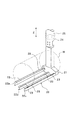
【図3】 この発明におけるウエハガイドを示す斜視図である。
【図4】 処理容器内のウエハにホットエアを供給した状態を示す概略断面図である。
【図5】 処理容器内のウエハにオゾンガスを供給した予備加圧の状態を示す概略断面図である。
【図6】 処理容器内のウエハに酸素ガスを供給した状態を示す概略断面図である。
【図7】 処理容器内の雰囲気ガスを排気した状態を示す概略断面図である。
【図8】 この発明に係る基板処理装置の第二実施形態の要部を示す断面図である。
【図9】 オゾンガスに窒素(N2)を含む場合と含まない場合のアルミニウム(Al)、銅(Cu)、タングステン(W)のエッチングレートを示すグラフである。
【図10】 ウエハの処理工程の一例を説明する概略断面図である。
【符号の説明】
W 半導体ウエハ(被処理基板)
10 処理容器
30 水蒸気供給手段
34 水蒸気供給管路
36 開閉弁
40,40A オゾンガス供給手段(処理ガス供給手段)
41,41A オゾンガス生成手段
48 スイッチ
49 開閉弁
50 内部排気手段
70 エア供給手段
72 ホットエアジェネレータ
73 ホットエア供給管路
76 開閉弁
90 排液手段
92 開閉弁
200 酸素供給管路
201 窒素供給管路
202,202A 流量調整弁
203 窒素供給管路[0001]
BACKGROUND OF THE INVENTION
The present invention relates to a substrate processing method and a substrate processing apparatus. More specifically, for example, a processing substrate such as a semiconductor wafer or a glass substrate for LCD is accommodated in a processing container in a sealed atmosphere, and a processing gas such as ozone gas is contained. The present invention relates to a substrate processing method and a substrate processing apparatus for supplying and processing.
[0002]
[Prior art]
In general, in a semiconductor device manufacturing process, a photoresist is applied to a semiconductor wafer, an LCD substrate, or the like (hereinafter referred to as a wafer) as a substrate to be processed, and a circuit pattern is reduced using a photolithography technique to form a photoresist. A series of processes for transferring and developing this, and then removing the photoresist from the wafer or the like are performed.
[0003]
An example of the above processing will be described with reference to FIG. 10 in the case where the substrate to be processed is, for example, a silicon wafer. First, a thick oxide film OX1 is formed on the surface of a silicon wafer W (hereinafter referred to as wafer W) {first oxide film formation step: see FIG. 10A}. Next, a resist is applied to the surface of the oxide film OX1 to form a resist pattern RP1 {first resist pattern forming step: see FIG. 10B}. Next, an unnecessary oxide film is etched using a chemical solution called DHF (HF / H 2 O), BHF {first etching step: see FIG. 10C}. After that, SPM (H2SO4/ H2O2Unnecessary resist is removed using a chemical solution (sulfuric acid / hydrogen peroxide mixture) called {mixed solution of the first solution} (first resist removing step: see FIG. 10D). Next, a thin oxide film OX2 is formed on the surface of the wafer W from which unnecessary resist has been removed {second oxide film formation step: see FIG. 10 (e)}. Next, a resist is again applied to the surface of the oxide film OX2 to form a resist pattern RP2 {second resist pattern forming step: see FIG. 10 (f)}. Next, an unnecessary oxide film is etched using a chemical solution such as DHF (HF / H 2 O), BHF, etc. {second etching step: see FIG. 10 (g)}. Finally, unnecessary resist is removed {second resist removing step: see FIG. 10 (h)}.
[0004]
In the conventional cleaning apparatus used as the means for removing the resist, generally, the SPM (H2SO4/ H2O2The wafer is dipped in a cleaning tank filled with a chemical solution such as (mixed solution of 2) (sulfuric acid / hydrogen peroxide) and the resist is peeled off.
[0005]
However, if a chemical solution such as sulfuric acid / hydrogen peroxide is used in the first resist removal step (see FIG. 10 (d)) of the above process, sulfate ions remain on the surface of the wafer W after the resist is removed. May cause particle generation and contamination. Furthermore, the remaining sulfate ions may cause a non-uniform thickness of the thin oxide film and a deterioration in film quality in the next second oxide film formation step (see FIG. 10E).
[0006]
On the other hand, in recent years, ozone (O3It is desired that the resist is removed using a solution in which () is dissolved. In this case, the resist is oxidized by oxygen atom radicals in the solution and decomposed into carbon dioxide, water, etc. by so-called dip cleaning, in which a wafer or the like is immersed in a cleaning tank filled with a solution in which ozone is dissolved. .
[0007]
By the way, generally, the solution is generated by bubbling high-concentration ozone gas in pure water and then dissolved, and then the solution is filled in the cleaning tank, so that the ozone in the solution disappears in the meantime. In some cases, the ozone concentration decreased and the resist could not be removed sufficiently. Furthermore, in the state where the wafer or the like is immersed in the solution, ozone reacts with the resist and disappears one after another, while the amount of ozone supplied to the resist surface becomes insufficient and a high reaction rate cannot be obtained. .
[0008]
Therefore, instead of a dip cleaning method that immerses a wafer or the like in a solution in which ozone is dissolved, a cleaning method for removing a resist from a wafer or the like using a processing gas such as ozone gas and a vapor of a solvent such as water vapor is proposed. Has been. This cleaning method is a method of removing a resist such as a wafer by supplying a processing gas such as ozone gas to a wafer or the like accommodated in a sealed processing container. By removing the resist using this ozone gas and water vapor, the problem of residual sulfate ions is eliminated, and the thickness of the thin oxide film can be made uniform and the film quality can be improved. In this case, ozone gas is oxygen (O2) To nitrogen (N2) Are mixed and generated by ozone generating means for discharging. Here, the reason why nitrogen is mixed with oxygen of the base gas is to increase the generation efficiency of ozone.
[0009]
[Problems to be solved by the invention]
However, since the ozone gas contains nitrogen as described above, nitrogen also flows into the processing container and contacts the wafer or the like with the supply of the ozone gas. When a wafer or the like comes into contact with nitrogen, there is a problem that a metal such as aluminum (Al) or tungsten (W) in the wiring portion is etched and corroded due to reaction with ozone gas and particles are generated. Further, there is a problem that metal contamination and particles are generated even on a wafer or the like that has not undergone a wiring process.
[0010]
In addition, when the treatment is performed with ozone gas containing nitrogen, the wafer or the like is further oxidized by the NOx or HNOx atmosphere (chemical), and thus a chemical oxide film grows on the surface of the wafer or the like. There is also a possibility that the thin oxide film may be uneven in film thickness and film quality may be deteriorated.
[0011]
The present invention has been made in view of the above circumstances, and provides a substrate processing method and a substrate processing apparatus capable of resist removal by suppressing metal contamination of a wafer or the like, generation of particles, and growth of an oxide film. It is the purpose.
[0012]
[Means for Solving the Problems]
In order to achieve the above object, the invention according to
[0013]
According to the second aspect of the present invention, there is provided a substrate to be processed accommodated in a sealed processing container.Ozone gasA substrate processing method for processing a substrate to be processed, wherein the processing container contains the substrate processing method.Ozone gasTo provide an ambient atmosphere around the substrate to be processed.In atmosphere only with ozone gasPressurizing, supplying a vapor of the solvent into the processing vessel, andOzone gasAnd stopping the supply of the vapor of the solvent,Ozone gasGeneration ofOzone gasAnd a step of stopping the supply of the base gas and exhausting the atmospheric gas in the processing vessel.
[0014]
The invention described in claim 3 is a substrate processing method for processing a substrate to be processed by supplying ozone gas to a substrate to be processed accommodated in a sealed processing container, wherein the ozone gas is supplied into the processing container. And the ambient atmosphere of the substrate to be processedIn atmosphere only with ozone gasA step of pressurizing, and supplying a vapor of the solvent into the processing vessel and supplying the ozone gas,In the step of supplying the vapor of the solvent to the substrate to be processed in the processing container and supplying the ozone gasThe nitrogen gas is supplied into the processing container, and the supply amount of the nitrogen gas is controlled.
[0015]
In the substrate processing method of the present invention, the substrate to be processed may be any substrate as long as it includes a metal, but preferably a semiconductor substrate having metal wiring (Claim 4).
[0016]
The invention according to claim 5 is a substrate processing apparatus for processing a substrate to be processed by supplying ozone gas to a substrate to be processed accommodated in a sealed processing container, and supplying the ozone gas into the processing container. Ozone gas supply means, solvent vapor supply means for supplying solvent vapor into the processing container, and supply of ozone gas and solvent vapor supplied into the processing container are controlled.At the same time, the supply of ozone gas is controlled so as to pressurize the inside of the processing container to an ozone gas atmosphere before processing.Supply control means; nitrogen gas supply means for supplying nitrogen gas into the processing container; and when the ozone gas and the solvent vapor are supplied into the processing container, the amount of nitrogen gas in the nitrogen gas supply means is adjusted. And nitrogen gas control means for controlling.
[0017]
The invention according to claim 6 is a substrate processing apparatus for processing a substrate to be processed by supplying ozone gas to a substrate to be processed accommodated in a sealed processing container, wherein the ozone gas is supplied into the processing container. Ozone gas supply means, solvent vapor supply means for supplying solvent vapor into the processing container, and supply of ozone gas and solvent vapor supplied into the processing container are controlled.At the same time, the supply of ozone gas is controlled so as to pressurize the inside of the processing container to an ozone gas atmosphere before processing.Supply control means; nitrogen gas supply means for supplying nitrogen gas into the processing container; and when the ozone gas and the solvent vapor are supplied into the processing container, the amount of nitrogen gas in the nitrogen gas supply means is adjusted. It comprises nitrogen gas control means for controlling, exhaust means for exhausting the atmosphere in the processing container, and exhaust amount adjusting means for adjusting the exhaust amount of the exhaust means.
[0018]
Claim 5 or 6In the described substrate processing apparatus, it is preferable that ozone gas or a base gas of ozone gas is formed so as to be supplied by operating or stopping the ozone gas generation means constituting the ozone gas supply means (Claim 7).
[0019]
7. The substrate processing apparatus according to claim 5, wherein the nitrogen gas supply means for supplying nitrogen gas into the processing container comprises a nitrogen supply pipe line provided with a flow rate adjusting valve, and the nitrogen gas control means. If it is necessary to remove the resist on the substrate to be processed and etch the metal, nitrogen gas is supplied together with ozone gas and solvent vapor to remove the resist on the substrate to be treated, and metal etching is required. If not, it is preferable to control the flow rate adjustment valve so as to supply only ozone gas and solvent vapor to control the amount of nitrogen gas in the nitrogen supply line (Claim 8)..
[0020]
7. The substrate processing apparatus according to claim 5, wherein a nitrogen supply line and an oxygen supply line provided with a flow rate adjusting valve are connected to the ozone gas generation means constituting the ozone gas supply means, and the supply is performed. When the control means needs to remove the resist on the substrate to be processed and etch the metal, it supplies oxygen and nitrogen to the ozone gas generating means, and requires the removal of the resist on the substrate to be processed. Is not necessary, it is preferable to control the flow rate adjusting valve so as to supply only the oxygen to the ozone gas generating means to control the amount of nitrogen gas in the nitrogen supply line (Claim 9)..
[0021]
According to the first aspect of the present invention, the substrate to be processed accommodated in the processing containerOzone gasBefore processing the substrate to be processed in the processing containerOzone gasTo increase the atmosphere in the processing container by pressurizing the ambient atmosphere of the substrate to be processed.Ozone gasWhile replacing with the atmosphere, the inside of the processing container can be pre-pressurized. Therefore, the substrate to be processed isOzone gasSince there is no fear of coming into contact with other gases or the like, metal contamination and generation of particles can be prevented. In addition, the solvent vapor supplied into the processing vessel nextOzone gasThe reaction rate can be increased to improve the processing efficiency.
[0022]
In addition, the atmosphere in the processing containerOzone gasIn addition to substituting with the atmosphere and pre-pressurizing the inside of the processing container, the vapor of the solvent supplied into the processing containerOzone gasAfter processing the substrate to be processed, the supply of the solvent vapor is stopped,Ozone gasGeneration ofOzone gasBy supplying the base gas, which is a raw material gas, into the processing container, rapid decompression in the processing container can be suppressed and condensation of solvent vapor can be suppressed. Accordingly, it is possible to prevent droplets from adhering to the object to be processed, and to improve the yield.
[0023]
According to invention of
[0024]
Claims 3, 5 and 6According to the described invention, before processing the substrate to be processed by supplying solvent vapor and ozone gas to the substrate to be processed accommodated in the processing container, the atmosphere around the substrate to be processed is supplied by supplying ozone gas into the processing container. , The atmosphere in the processing container can be replaced with an ozone gas atmosphere, and the inside of the processing container can be pre-pressurized. Therefore, there is no possibility that the substrate to be processed comes into contact with a gas other than ozone gas, so that metal contamination and generation of particles can be prevented. Further, it is possible to improve the processing efficiency by increasing the reaction rate between the vapor of the solvent supplied into the processing container and ozone gas. Furthermore, the amount of metal etching can be controlled by controlling the supply amount of nitrogen gas. Therefore, it is suitable for processing a substrate to be processed that does not have a wiring process. Furthermore, by suppressing the supply amount of nitrogen gas, growth of an oxide film formed on the surface of the substrate to be processed can be suppressed. Therefore, generation of particles and contamination can be prevented regardless of the presence or absence of metal wiring, and the film thickness can be made uniform and the film quality improved when a thin oxide film is formed.
[0025]
DETAILED DESCRIPTION OF THE INVENTION
Embodiments of the present invention will be described below in detail with reference to the drawings. In this embodiment, a case where a resist is removed from a semiconductor wafer W (hereinafter referred to as a wafer W) using ozone gas will be described.
[0026]
FIG. 1 is a schematic cross-sectional view showing an example of a substrate processing apparatus according to the present invention, and FIG. 2 is a cross-sectional view showing a main part of the substrate processing apparatus.
[0027]
The substrate processing apparatus includes a
[0028]
The
[0029]
The
[0030]
Further, a
[0031]
A
[0032]
As shown in FIG. 3, the
[0033]
The water vapor supply means 30 includes a pure
[0034]
In this case, one end of the pure
[0035]
On the other hand, the ozone gas supply means 40 includes an ozone gas generation means 41, an ozone
[0036]
In this case, the ozone gas generation means 41 is oxygen (O2) Is passed between the
[0037]
The air supply means 70 supplies an
[0038]
In this case, an air supply source 75 is connected to one end of the
[0039]
The internal exhaust means 50 is connected to an
[0040]
In this case, the
[0041]
The cooling
[0042]
The
[0043]
The second
[0044]
The
[0045]
The
[0046]
Further, the
[0047]
The
[0048]
Further, the
[0049]
The ambient exhaust means 60 includes a
[0050]
In the
[0051]
The first
[0052]
The second
[0053]
The exhaust means 90 includes a
[0054]
In the
[0055]
Next, operation modes of the substrate processing apparatus according to the present invention will be described with reference to FIGS. 2 and 4 to 7. First, a plurality of, for example, 50 wafers W transferred by a wafer transfer means (not shown) are transferred to the
[0056]
In the state in which the wafer W is accommodated in the
[0057]
Next, as shown in FIG. 5, the ozone gas supply means 41, which is an ozone gas supply means, operates to supply oxygen (O2) Apply high frequency voltage to ozone (O3) While generating gas, the on-off
[0058]
After performing pre-pressurization in the
[0059]
Processing is carried out for a predetermined time (for example, 3 to 6 minutes), depending on the type of resist, but the pressure in the
[0060]
After supplying oxygen for a predetermined time (for example, 1 minute), the supply of oxygen is stopped, and then the forced
[0061]
Thereafter, the elevating
[0062]
Therefore, according to the substrate processing, resist removal of the wafer W having a wiring process, prevention of metal corrosion and prevention of particles, as well as resist removal of other wafers W not having a wiring process, prevention of metal corrosion and prevention of particles. It can also be applied to prevention.
[0063]
FIG. 8 is a cross-sectional view of an essential part showing a second embodiment of the substrate processing apparatus according to the present invention. In the embodiment, in order to remove the resist of the wafer W, prevent metal corrosion, and prevent particles, the ozone gas supply means 40 that is a process gas supply means is oxygen (O2) Only the case of ozonization by discharge has been described. In the second embodiment, the ozone gas generation means 41 of the ozone gas supply means 40 which is a processing gas supply means is supplied with oxygen (O2) And nitrogen (N2) To improve the efficiency of ozone gasification, and the nitrogen supply amount is controlled so that the resist removal of the wafer W and the metal etching amount can be controlled.
[0064]
That is, in the second embodiment, a
[0065]
By supplying nitrogen together with oxygen to the ozone gas generating means 41A in this way, oxygen molecules adhering to the
[0066]
In the above description, nitrogen (N2) And nitrogen (N in ozone gas)28), as shown by a two-dot chain line in FIG. 8, the
[0067]
In the second embodiment, the other parts are the same as those in the first embodiment. Therefore, the same parts are denoted by the same reference numerals and description thereof is omitted.
[0068]
In the second embodiment, the case where the supply amount of nitrogen is controlled to remove the resist of the wafer W and the metal etching amount is controlled has been described. However, the growth amount of the oxide film is controlled by controlling the supply amount of nitrogen. It can also be suppressed. That is, by applying the processing method of the present invention to the first resist removal step (see FIG. 10D) in the processing step shown in FIG. 10, the growth of the chemical oxide film on the surface of the wafer W is suppressed. Therefore, it is possible to make the thickness of the thin oxide film uniform and improve the film quality.
[0069]
In the above-described embodiment, the case where the substrate to be processed is the wafer W has been described. However, the substrate to be processed is not necessarily the wafer W. For example, if the substrate to be processed is a resist-coated substrate or a metal coating, For example, a substrate such as an LCD substrate or a CD may be used.
[0070]
【Example】
Example 1
Nitrogen (N2) And nitrogen (N2In order to investigate the etching rate of the metal when it is not included, an experiment was conducted under the following conditions.
[0071]
Experimental conditions
A) Sample metal: Aluminum (Al), Copper (Cu), Tungsten (W)
B) Processing conditions
1) Nitrogen (N2)
・ Pressure: 14.7 [kPa]
-Wafer temperature: 80 [° C]
・ Water vapor temperature: 100 [° C.]
・ Processing time: 5 [min]
2) Nitrogen (N2)
・ Pressure: 980.7 [kPa]
-Wafer temperature: 80 [° C]
・ Water vapor temperature: 124 [° C]
・ Processing time: 5 [min]
When an experiment was conducted under the above-mentioned conditions, a result as shown in FIG. 9 was obtained.
[0072]
For example, in aluminum (Al), nitrogen (N2) Is included in the etching rate86.38Although it was [Å / min], in the case of only ozone gas, it was hardly etched and was −1.06 [Å / min]. In addition, in copper (Cu), nitrogen (N2) Was 100 [Å / min] or more, but in the case of ozone gas alone, it was 22.28 [Å / min]. The etching rate in the case of tungsten (W) was 45.82 [Å / min], but in the case of only ozone gas, it was 3.32 [Å / min].
[0073]
As a result of the experiment, nitrogen (N2) Was included, it was found that metals such as aluminum (Al), copper (Cu) and tungsten (W) can be etched significantly. Therefore, nitrogen (N2), That is, the amount of etching of the metal can be controlled by appropriately changing (controlling) the conditions such as pressure and temperature.
[0074]
Example 2
Nitrogen in ozone gas (N2In order to investigate the growth amount of the chemical oxide film before and after the treatment in the resist removal treatment depending on the addition amount (content)), an experiment was performed under the following conditions.
[0075]
Experimental conditions
Ozone gas: 10 liters / minute (
Water vapor: 120 ° C
Wafer temperature: 90 ° C
Pressure: 0.05 MPa (zero adjustment at atmospheric pressure of 0.1 MPa)
Ozone gas / water vapor supply time: 5 minutes
N2 supply rate: 0.08 l / min
When the experiment was conducted under the above conditions, the results shown in Table 1 were obtained.
[0076]
[Table 1]
As a result of the experiment, N2Additive ozone gas (OThreeIn the case of performing the resist removal treatment at a concentration of 10%), the thickness of the oxide film before the treatment was 3.35 mm, but the thickness of the oxide film after the treatment was 16.90 mm, and the growth amount of the oxide film Was 13.55 cm. In contrast, N2Additive-free ozone gas (OThreeIn the case of performing the resist removal processing at a concentration of 4%), the thickness of the oxide film before the processing is 3.70 mm, the thickness of the oxide film after the processing is 11.23 mm, and the growth amount of the oxide film is 7 It was .54cm.
[0078]
Therefore, N2By removing the resist with additive-free ozone gas, N2It has been found that the growth amount of the oxide film can be suppressed by 13.55 to 7.54 = 6.01 (Å) as compared with the case where the resist removal process is performed with the added ozone gas.
[0079]
Normally, the thin oxide film OX2 of FIG. 10E formed by a furnace, for example, is required to be about 10 to 15 mm.2When the treatment is performed with the added ozone gas, the oxide film thickness after the process becomes 16.90 mm, which exceeds the maximum value of 15 mm of the required film thickness. But N2In the case of treatment with additive-free ozone gas, the oxide film thickness after treatment is 11.23 mm, which is within the range of the required film thickness. Therefore, the film quality is higher (density is higher) by the furnace, and the film thickness is increased. A uniform thin oxide film can be formed.
[0080]
In the experiment, N2The case where the supply amount is 0.08 liter / min and 0 (zero) has been described.2The thickness of the oxide film before and after the resist removal process based on the supply amount is obtained by experiments, and experimental data of other conditions are obtained and stored in the
[0081]
【The invention's effect】
As described above, according to the present invention, since it is configured as described above, the following effects can be obtained.
[0082]
1) According to the invention described in
[0083]
2) In addition, the atmosphere in the processing containerOzone gasIn addition to substituting with the atmosphere and pre-pressurizing the inside of the processing container, the vapor of the solvent supplied into the processing containerOzone gasAfter processing the substrate to be processed, the supply of the solvent vapor is stopped,Ozone gasGeneration ofOzone gasBy supplying this base gas into the processing container, it is possible to suppress rapid depressurization in the processing container and to prevent condensation of the solvent vapor. Therefore, in addition to the above 1), it is possible to further prevent droplets from adhering to the object to be processed.CanYield can be improved.
[0084]
3) According to the invention of
[0085]
4) Claims 3, 5 and 6According to the described invention, before processing the substrate to be processed by supplying solvent vapor and ozone gas to the substrate to be processed accommodated in the processing container, the atmosphere around the substrate to be processed is supplied by supplying ozone gas into the processing container. , The atmosphere in the processing container can be replaced with an ozone gas atmosphere, and the inside of the processing container can be pre-pressurized. Therefore, there is no possibility that the substrate to be processed comes into contact with a gas other than ozone gas, so that metal contamination and generation of particles can be prevented. Further, it is possible to improve the processing efficiency by increasing the reaction rate between the vapor of the solvent supplied into the processing container and ozone gas. Furthermore, the amount of metal etching can be controlled by controlling the supply amount of nitrogen gas. Therefore, it is suitable for processing a substrate to be processed that does not have a wiring process. Furthermore, by suppressing the supply amount of nitrogen gas, growth of an oxide film formed on the surface of the substrate to be processed can be suppressed. Therefore, generation of particles and contamination can be prevented regardless of the presence or absence of metal wiring, and the film thickness can be made uniform and the film quality improved when a thin oxide film is formed.
[Brief description of the drawings]
FIG. 1 is a schematic cross-sectional view showing a first embodiment of a substrate processing apparatus according to the present invention.
FIG. 2 is a cross-sectional view showing a main part of the substrate processing apparatus of the first embodiment and showing a state in which water vapor and ozone gas are supplied to a wafer in a processing container.
FIG. 3 is a perspective view showing a wafer guide according to the present invention.
FIG. 4 is a schematic cross-sectional view showing a state in which hot air is supplied to a wafer in a processing container.
FIG. 5 is a schematic cross-sectional view showing a pre-pressurized state in which ozone gas is supplied to a wafer in a processing container.
FIG. 6 is a schematic cross-sectional view showing a state in which oxygen gas is supplied to a wafer in a processing container.
FIG. 7 is a schematic cross-sectional view showing a state where the atmospheric gas in the processing container is exhausted.
FIG. 8 is a cross-sectional view showing the main part of a second embodiment of the substrate processing apparatus according to the present invention.
[Fig. 9] Nitrogen (N2Is a graph showing etching rates of aluminum (Al), copper (Cu), and tungsten (W) with and without.
FIG. 10 is a schematic cross-sectional view illustrating an example of a wafer processing process.
[Explanation of symbols]
W Semiconductor wafer (substrate to be processed)
10 Processing container
30 Water vapor supply means
34 Water vapor supply line
36 On-off valve
40, 40A ozone gas supply means (process gas supply means)
41, 41A Ozone gas generation means
48 switches
49 On-off valve
50 Internal exhaust means
70 Air supply means
72 Hot Air Generator
73 Hot air supply line
76 On-off valve
90 Drainage means
92 On-off valve
200 oxygen supply line
201 Nitrogen supply line
202, 202A Flow control valve
203 Nitrogen supply line
Claims (9)
前記処理容器内に前記オゾンガスを供給して前記被処理基板の周囲雰囲気をオゾンガスのみの雰囲気に加圧する工程と、
前記処理容器内に溶媒の蒸気を供給すると共に、前記オゾンガスを供給する工程と、
前記溶媒の蒸気の供給を停止すると共に、オゾンガスの生成を停止し、オゾンガスの基ガスを処理容器内に供給する工程と、
を有することを特徴とする基板処理方法。A substrate processing method for processing a substrate to be processed by supplying ozone gas to a substrate to be processed contained in a sealed processing container,
Supplying the ozone gas into the processing container to pressurize the ambient atmosphere of the substrate to be processed into an atmosphere containing only ozone gas;
Supplying the solvent vapor into the processing vessel and supplying the ozone gas;
Stopping the supply of the vapor of the solvent, stopping the generation of ozone gas, and supplying a base gas of ozone gas into the processing vessel;
A substrate processing method comprising:
前記処理容器内に前記オゾンガスを供給して前記被処理基板の周囲雰囲気をオゾンガスのみの雰囲気に加圧する工程と、
前記処理容器内に溶媒の蒸気を供給すると共に、前記オゾンガスを供給する工程と、
前記溶媒の蒸気の供給を停止すると共に、オゾンガスの生成を停止し、オゾンガスの基ガスを処理容器内に供給する工程と、
前記基ガスの供給を停止すると共に、処理容器内の雰囲気ガスを排気する工程と、
を有することを特徴とする基板処理方法。A substrate processing method for processing a substrate to be processed by supplying ozone gas to a substrate to be processed contained in a sealed processing container,
Supplying the ozone gas into the processing container to pressurize the ambient atmosphere of the substrate to be processed into an atmosphere containing only ozone gas;
Supplying the solvent vapor into the processing vessel and supplying the ozone gas;
Stopping the supply of the vapor of the solvent, stopping the generation of ozone gas, and supplying a base gas of ozone gas into the processing vessel;
A step of stopping the supply of the base gas and exhausting the atmospheric gas in the processing container;
A substrate processing method comprising:
前記処理容器内に前記オゾンガスを供給して前記被処理基板の周囲雰囲気をオゾンガスのみの雰囲気に加圧する工程と、
前記処理容器内に溶媒の蒸気を供給すると共に、前記オゾンガスを供給する工程と、を有し、
前記処理容器内の前記被処理基板に溶媒の蒸気を供給すると共に、前記オゾンガスを供給する工程の際に、前記処理容器内に窒素ガスを供給すると共に、該窒素ガスの供給量を制御することを特徴とする基板処理方法。A substrate processing method for processing a substrate to be processed by supplying ozone gas to a substrate to be processed contained in a sealed processing container,
Supplying the ozone gas into the processing container to pressurize the ambient atmosphere of the substrate to be processed into an atmosphere containing only ozone gas;
Supplying the vapor of the solvent into the processing vessel and supplying the ozone gas,
In the step of supplying the vapor of the solvent to the substrate to be processed in the processing container and supplying the ozone gas, supplying nitrogen gas into the processing container and controlling the supply amount of the nitrogen gas. A substrate processing method.
上記被処理基板は、金属の配線がされている半導体基板であることを特徴とする基板処理方法。In the substrate processing method in any one of Claim 1 thru | or 3,
The substrate processing method is characterized in that the substrate to be processed is a semiconductor substrate on which metal wiring is provided.
前記処理容器内にオゾンガスを供給するオゾンガス供給手段と、
前記処理容器内に溶媒の蒸気を供給する溶媒蒸気供給手段と、
前記処理容器内に供給されるオゾンガス及び溶媒蒸気の供給を制御すると共に、処理前に前記処理容器内をオゾンガスの雰囲気に加圧すべくオゾンガスの供給を制御する供給制御手段と、
前記処理容器内に窒素ガスを供給する窒素ガス供給手段と、
前記処理容器内に前記オゾンガスと前記溶媒蒸気が供給されている際に、前記窒素ガス供給手段の窒素ガス量を制御する窒素ガス制御手段と、
を具備することを特徴とする基板処理装置。A substrate processing apparatus for processing a substrate to be processed by supplying ozone gas to a substrate to be processed contained in a sealed processing container,
Ozone gas supply means for supplying ozone gas into the processing vessel;
Solvent vapor supply means for supplying a vapor of the solvent into the processing vessel;
A supply control means for controlling the supply of ozone gas and solvent vapor supplied into the processing container, and for controlling the supply of ozone gas so as to pressurize the inside of the processing container to an atmosphere of ozone gas before processing ;
Nitrogen gas supply means for supplying nitrogen gas into the processing vessel;
A nitrogen gas control means for controlling the amount of nitrogen gas in the nitrogen gas supply means when the ozone gas and the solvent vapor are supplied into the processing container;
A substrate processing apparatus comprising:
前記処理容器内にオゾンガスを供給するオゾンガス供給手段と、
前記処理容器内に溶媒の蒸気を供給する溶媒蒸気供給手段と、
前記処理容器内に供給されるオゾンガス及び溶媒蒸気の供給を制御すると共に、処理前に前記処理容器内をオゾンガスの雰囲気に加圧すべくオゾンガスの供給を制御する供給制御手段と、
前記処理容器内に窒素ガスを供給する窒素ガス供給手段と、
前記処理容器内に前記オゾンガスと前記溶媒蒸気が供給されている際に、前記窒素ガス供給手段の窒素ガス量を制御する窒素ガス制御手段と、
前記処理容器内の雰囲気を排気する排気手段と、
前記排気手段の排気量を調整する排気量調整手段と、
を具備することを特徴とする基板処理装置。A substrate processing apparatus for processing a substrate to be processed by supplying ozone gas to a substrate to be processed contained in a sealed processing container,
Ozone gas supply means for supplying ozone gas into the processing vessel;
Solvent vapor supply means for supplying a vapor of the solvent into the processing vessel;
A supply control means for controlling the supply of ozone gas and solvent vapor supplied into the processing container, and for controlling the supply of ozone gas so as to pressurize the inside of the processing container to an atmosphere of ozone gas before processing ;
Nitrogen gas supply means for supplying nitrogen gas into the processing vessel;
A nitrogen gas control means for controlling the amount of nitrogen gas in the nitrogen gas supply means when the ozone gas and the solvent vapor are supplied into the processing container;
Exhaust means for exhausting the atmosphere in the processing vessel;
An exhaust amount adjusting means for adjusting an exhaust amount of the exhaust means;
A substrate processing apparatus comprising:
前記オゾンガス供給手段を構成するオゾンガス生成手段の作動又は停止によりオゾンガス又はオゾンガスの基ガスを供給可能に形成してなることを特徴とする基板処理装置。The substrate processing apparatus according to claim 5 or 6,
A substrate processing apparatus, wherein ozone gas or a base gas of ozone gas can be supplied by operating or stopping an ozone gas generating means constituting the ozone gas supply means.
前記処理容器内に窒素ガスを供給する窒素ガス供給手段は、流量調整弁を介設する窒素供給管路を具備し、
前記窒素ガス制御手段は、
被処理基板上のレジストの除去及び金属のエッチングを必要とする場合は、オゾンガス及び溶媒蒸気と共に窒素ガスを供給し、
被処理基板上のレジストの除去を必要とし、金属のエッチングを必要としない場合は、オゾンガスと溶媒蒸気のみを供給するように、
前記流量調整弁を制御して前記窒素供給管路の窒素ガス量を制御することを特徴とする基板処理装置。The substrate processing apparatus according to claim 5 or 6,
The nitrogen gas supply means for supplying nitrogen gas into the processing vessel comprises a nitrogen supply pipe line provided with a flow rate adjusting valve,
The nitrogen gas control means includes
When it is necessary to remove the resist on the substrate to be processed and etch the metal, supply nitrogen gas together with ozone gas and solvent vapor,
If it is necessary to remove the resist on the substrate to be processed, and metal etching is not required, supply only ozone gas and solvent vapor.
A substrate processing apparatus, wherein the flow rate adjusting valve is controlled to control the amount of nitrogen gas in the nitrogen supply line.
前記オゾンガス供給手段を構成するオゾンガス生成手段に、流量調整弁を介設する窒素供給管路と、酸素供給管路とを接続し、
前記供給制御手段は、
被処理基板上のレジストの除去及び金属のエッチングを必要とする場合は、酸素と窒素を前記オゾンガス生成手段に供給し、
被処理基板上のレジストの除去を必要とし、金属のエッチングを必要としない場合は、酸素のみを前記オゾンガス生成手段に供給するように、
前記流量調整弁を制御して前記窒素供給管路の窒素ガス量を制御することを特徴とする基板処理装置。The substrate processing apparatus according to claim 5 or 6,
A nitrogen supply line provided with a flow rate adjustment valve and an oxygen supply line are connected to the ozone gas generation means constituting the ozone gas supply means,
The supply control means includes
When it is necessary to remove the resist on the substrate to be processed and etch the metal, supply oxygen and nitrogen to the ozone gas generating means,
If it is necessary to remove the resist on the substrate to be processed and etching of the metal is not required, only oxygen is supplied to the ozone gas generating means.
A substrate processing apparatus, wherein the flow rate adjusting valve is controlled to control the amount of nitrogen gas in the nitrogen supply line.
Priority Applications (4)
| Application Number | Priority Date | Filing Date | Title |
|---|---|---|---|
| JP2001041482A JP4014127B2 (en) | 2000-10-04 | 2001-02-19 | Substrate processing method and substrate processing apparatus |
| KR1020010060911A KR100849254B1 (en) | 2000-10-04 | 2001-09-29 | Substrate processing method and substrate processing apparatus |
| US09/971,136 US6817368B2 (en) | 2000-10-04 | 2001-10-03 | Substrate processing method and substrate processing apparatus |
| US10/957,003 US7410543B2 (en) | 2000-10-04 | 2004-10-01 | Substrate processing method |
Applications Claiming Priority (3)
| Application Number | Priority Date | Filing Date | Title |
|---|---|---|---|
| JP2000-304375 | 2000-10-04 | ||
| JP2000304375 | 2000-10-04 | ||
| JP2001041482A JP4014127B2 (en) | 2000-10-04 | 2001-02-19 | Substrate processing method and substrate processing apparatus |
Publications (3)
| Publication Number | Publication Date |
|---|---|
| JP2002184741A JP2002184741A (en) | 2002-06-28 |
| JP2002184741A5 JP2002184741A5 (en) | 2005-03-17 |
| JP4014127B2 true JP4014127B2 (en) | 2007-11-28 |
Family
ID=26601499
Family Applications (1)
| Application Number | Title | Priority Date | Filing Date |
|---|---|---|---|
| JP2001041482A Expired - Fee Related JP4014127B2 (en) | 2000-10-04 | 2001-02-19 | Substrate processing method and substrate processing apparatus |
Country Status (3)
| Country | Link |
|---|---|
| US (2) | US6817368B2 (en) |
| JP (1) | JP4014127B2 (en) |
| KR (1) | KR100849254B1 (en) |
Families Citing this family (31)
| Publication number | Priority date | Publication date | Assignee | Title |
|---|---|---|---|---|
| KR100899609B1 (en) * | 2000-12-28 | 2009-05-27 | 도쿄엘렉트론가부시키가이샤 | Substrate processing apparatus and substrate processing method |
| JP2002353184A (en) * | 2001-05-28 | 2002-12-06 | Tokyo Electron Ltd | Substrate processing method and substrate processor |
| WO2003064065A1 (en) * | 2002-01-25 | 2003-08-07 | Supercritical Systems Inc. | Method for reducing the formation of contaminants during supercritical carbon dioxide processes |
| US7387868B2 (en) * | 2002-03-04 | 2008-06-17 | Tokyo Electron Limited | Treatment of a dielectric layer using supercritical CO2 |
| KR100863782B1 (en) * | 2002-03-08 | 2008-10-16 | 도쿄엘렉트론가부시키가이샤 | Substrate processing apparatus and substrate processing method |
| JP3953361B2 (en) * | 2002-05-08 | 2007-08-08 | 東京エレクトロン株式会社 | Substrate processing apparatus and substrate processing method |
| US20040159335A1 (en) * | 2002-05-17 | 2004-08-19 | P.C.T. Systems, Inc. | Method and apparatus for removing organic layers |
| JP3999059B2 (en) * | 2002-06-26 | 2007-10-31 | 東京エレクトロン株式会社 | Substrate processing system and substrate processing method |
| KR100475272B1 (en) * | 2002-06-29 | 2005-03-10 | 주식회사 하이닉스반도체 | Manufacturing Method of Semiconductor Device |
| WO2004012259A1 (en) * | 2002-07-25 | 2004-02-05 | Tokyo Electron Limited | Substrate processing container |
| AU2003290835A1 (en) * | 2002-12-10 | 2004-06-30 | Semitool, Inc. | Workpiece processing system |
| JP4318930B2 (en) * | 2003-02-19 | 2009-08-26 | 東京エレクトロン株式会社 | Substrate processing method |
| US20050022850A1 (en) * | 2003-07-29 | 2005-02-03 | Supercritical Systems, Inc. | Regulation of flow of processing chemistry only into a processing chamber |
| US20050067002A1 (en) * | 2003-09-25 | 2005-03-31 | Supercritical Systems, Inc. | Processing chamber including a circulation loop integrally formed in a chamber housing |
| KR100728547B1 (en) | 2003-12-18 | 2007-06-15 | 동경 엘렉트론 주식회사 | Substrate treating method, substrate treating device and computer readable recording medium |
| GB2411384B (en) * | 2004-02-25 | 2006-09-06 | Mark Jason Starnes | Thin turntable |
| US20060060232A1 (en) * | 2004-04-15 | 2006-03-23 | Tokyo Electron Limited | Liquid treatment device and liquid treatment method |
| JP4459774B2 (en) | 2004-10-12 | 2010-04-28 | 東京エレクトロン株式会社 | Substrate processing method, substrate processing apparatus, and computer program |
| US20060102282A1 (en) * | 2004-11-15 | 2006-05-18 | Supercritical Systems, Inc. | Method and apparatus for selectively filtering residue from a processing chamber |
| US20060128160A1 (en) * | 2004-12-10 | 2006-06-15 | Yoo Woo S | Photoresist strip using solvent vapor |
| US7767145B2 (en) * | 2005-03-28 | 2010-08-03 | Toyko Electron Limited | High pressure fourier transform infrared cell |
| US20060226117A1 (en) * | 2005-03-29 | 2006-10-12 | Bertram Ronald T | Phase change based heating element system and method |
| US20060225772A1 (en) * | 2005-03-29 | 2006-10-12 | Jones William D | Controlled pressure differential in a high-pressure processing chamber |
| US20060225769A1 (en) * | 2005-03-30 | 2006-10-12 | Gentaro Goshi | Isothermal control of a process chamber |
| JP2007165842A (en) * | 2005-11-21 | 2007-06-28 | Dainippon Screen Mfg Co Ltd | Substrate processing method and its apparatus |
| JP4786351B2 (en) | 2006-01-20 | 2011-10-05 | 株式会社東芝 | Processing apparatus and processing method |
| JP4901323B2 (en) * | 2006-06-20 | 2012-03-21 | 東京応化工業株式会社 | Substrate processing equipment |
| JP5399678B2 (en) * | 2008-10-02 | 2014-01-29 | 芝浦メカトロニクス株式会社 | Resist stripping device |
| RU2548835C1 (en) * | 2013-11-01 | 2015-04-20 | Елена Анатольевна Чекалова | Making of wear-proof coating on metal part surface |
| KR20180085088A (en) * | 2017-01-16 | 2018-07-26 | 삼성디스플레이 주식회사 | Photoresist stripping apparatus, methods of stripping photoresist and forming thin film pattern using the same |
| KR20200092530A (en) * | 2019-01-24 | 2020-08-04 | 삼성전자주식회사 | Apparatus for removing photoresists and method of manufacturing semiconductor device by using the same |
Family Cites Families (24)
| Publication number | Priority date | Publication date | Assignee | Title |
|---|---|---|---|---|
| US4778532A (en) * | 1985-06-24 | 1988-10-18 | Cfm Technologies Limited Partnership | Process and apparatus for treating wafers with process fluids |
| US4749440A (en) * | 1985-08-28 | 1988-06-07 | Fsi Corporation | Gaseous process and apparatus for removing films from substrates |
| US4812201A (en) * | 1986-07-25 | 1989-03-14 | Tokyo Electron Limited | Method of ashing layers, and apparatus for ashing layers |
| US5174855A (en) * | 1989-04-28 | 1992-12-29 | Dainippon Screen Mfg. Co. Ltd. | Surface treating apparatus and method using vapor |
| US5288333A (en) * | 1989-05-06 | 1994-02-22 | Dainippon Screen Mfg. Co., Ltd. | Wafer cleaning method and apparatus therefore |
| JPH04125927A (en) * | 1990-09-18 | 1992-04-27 | Fujitsu Ltd | Method of washing substrate |
| US5370846A (en) | 1990-10-26 | 1994-12-06 | Sumitomo Precision Products Co., Ltd. | Apparatus and method for generating high concentration ozone |
| JP2583152B2 (en) * | 1990-11-06 | 1997-02-19 | 大日本スクリーン製造株式会社 | Substrate rotating surface treatment method |
| KR940012061A (en) * | 1992-11-27 | 1994-06-22 | 가나이 쯔또무 | Organic matter removal method and organic matter removal apparatus for using the method |
| US5729423A (en) * | 1994-01-31 | 1998-03-17 | Applied Materials, Inc. | Puncture resistant electrostatic chuck |
| JP3080834B2 (en) * | 1994-03-30 | 2000-08-28 | 株式会社東芝 | Semiconductor substrate cleaning equipment |
| US5845660A (en) * | 1995-12-07 | 1998-12-08 | Tokyo Electron Limited | Substrate washing and drying apparatus, substrate washing method, and substrate washing apparatus |
| US6248398B1 (en) * | 1996-05-22 | 2001-06-19 | Applied Materials, Inc. | Coater having a controllable pressurized process chamber for semiconductor processing |
| US5922138A (en) * | 1996-08-12 | 1999-07-13 | Tokyo Electron Limited | Liquid treatment method and apparatus |
| JP3171807B2 (en) * | 1997-01-24 | 2001-06-04 | 東京エレクトロン株式会社 | Cleaning device and cleaning method |
| US6551409B1 (en) * | 1997-02-14 | 2003-04-22 | Interuniversitair Microelektronica Centrum, Vzw | Method for removing organic contaminants from a semiconductor surface |
| US6701941B1 (en) * | 1997-05-09 | 2004-03-09 | Semitool, Inc. | Method for treating the surface of a workpiece |
| JPH11209876A (en) * | 1998-01-26 | 1999-08-03 | Nippon Asm Kk | Thin film forming device and its method |
| KR19990069185A (en) * | 1998-02-05 | 1999-09-06 | 윤종용 | Development apparatus of semiconductor wafer and developing method using the same |
| KR100266681B1 (en) * | 1998-04-18 | 2000-10-02 | 김영환 | Cleaning apparatus for semiconductor wafer manufacturing etching equipment |
| US6178973B1 (en) * | 1998-07-28 | 2001-01-30 | International Business Machines Corporation | Method and apparatus for ozone generation and surface treatment |
| KR100735876B1 (en) * | 1999-07-30 | 2007-07-06 | 동경 엘렉트론 주식회사 | Substrate processing method and substrate processing apparatus |
| US6588437B1 (en) * | 1999-11-15 | 2003-07-08 | Agere Systems Inc. | System and method for removal of material |
| KR20030019323A (en) * | 2000-03-13 | 2003-03-06 | 맷슨 테크날러지 아이피 | Processes and apparatus for treating electronic components |
-
2001
- 2001-02-19 JP JP2001041482A patent/JP4014127B2/en not_active Expired - Fee Related
- 2001-09-29 KR KR1020010060911A patent/KR100849254B1/en not_active IP Right Cessation
- 2001-10-03 US US09/971,136 patent/US6817368B2/en not_active Expired - Fee Related
-
2004
- 2004-10-01 US US10/957,003 patent/US7410543B2/en not_active Expired - Fee Related
Also Published As
| Publication number | Publication date |
|---|---|
| KR100849254B1 (en) | 2008-07-29 |
| US20050051246A1 (en) | 2005-03-10 |
| US20020045008A1 (en) | 2002-04-18 |
| JP2002184741A (en) | 2002-06-28 |
| US6817368B2 (en) | 2004-11-16 |
| US7410543B2 (en) | 2008-08-12 |
| KR20020027202A (en) | 2002-04-13 |
Similar Documents
| Publication | Publication Date | Title |
|---|---|---|
| JP4014127B2 (en) | Substrate processing method and substrate processing apparatus | |
| JP2002184741A5 (en) | ||
| KR100709982B1 (en) | Substrate processing method and substrate processing apparatus | |
| JP2001176833A (en) | Substrate processor | |
| US6869499B2 (en) | Substrate processing method and substrate processing apparatus | |
| JP3545672B2 (en) | Substrate processing method and substrate processing apparatus | |
| KR20030087543A (en) | Substrate processing apparatus and substrate processing method | |
| JP4014126B2 (en) | Substrate processing method and substrate processing apparatus | |
| JP3544329B2 (en) | Substrate processing equipment | |
| JP2003224102A (en) | Substrate treatment equipment and substrate treatment method | |
| JP2007266636A (en) | Substrate treatment device | |
| JP4562109B2 (en) | Substrate processing equipment | |
| JP4536711B2 (en) | Substrate processing equipment | |
| JP2003266004A (en) | Steam production apparatus and substrate treatment apparatus provided with the same | |
| JP3544336B2 (en) | Substrate processing method | |
| JP3979691B2 (en) | Substrate processing method and substrate processing apparatus | |
| JP3651395B2 (en) | Substrate processing method and substrate processing apparatus | |
| JP2003273085A (en) | Substrate-processing method and substrate-processing apparatus | |
| JP4053976B2 (en) | Substrate processing method and substrate processing apparatus | |
| JP3544326B2 (en) | Substrate processing method | |
| JP3989355B2 (en) | Processing apparatus and processing method | |
| JP4053975B2 (en) | Substrate processing method | |
| JP3544341B2 (en) | Substrate processing method | |
| JP2004152892A (en) | Method and device for treatment |
Legal Events
| Date | Code | Title | Description |
|---|---|---|---|
| A521 | Written amendment |
Free format text: JAPANESE INTERMEDIATE CODE: A523 Effective date: 20040422 |
|
| A621 | Written request for application examination |
Free format text: JAPANESE INTERMEDIATE CODE: A621 Effective date: 20040422 |
|
| A977 | Report on retrieval |
Free format text: JAPANESE INTERMEDIATE CODE: A971007 Effective date: 20060511 |
|
| A131 | Notification of reasons for refusal |
Free format text: JAPANESE INTERMEDIATE CODE: A131 Effective date: 20061107 |
|
| A521 | Written amendment |
Free format text: JAPANESE INTERMEDIATE CODE: A523 Effective date: 20061220 |
|
| A131 | Notification of reasons for refusal |
Free format text: JAPANESE INTERMEDIATE CODE: A131 Effective date: 20070619 |
|
| A521 | Written amendment |
Free format text: JAPANESE INTERMEDIATE CODE: A523 Effective date: 20070803 |
|
| TRDD | Decision of grant or rejection written | ||
| A01 | Written decision to grant a patent or to grant a registration (utility model) |
Free format text: JAPANESE INTERMEDIATE CODE: A01 Effective date: 20070907 |
|
| A61 | First payment of annual fees (during grant procedure) |
Free format text: JAPANESE INTERMEDIATE CODE: A61 Effective date: 20070907 |
|
| FPAY | Renewal fee payment (event date is renewal date of database) |
Free format text: PAYMENT UNTIL: 20100921 Year of fee payment: 3 |
|
| R150 | Certificate of patent or registration of utility model |
Free format text: JAPANESE INTERMEDIATE CODE: R150 |
|
| FPAY | Renewal fee payment (event date is renewal date of database) |
Free format text: PAYMENT UNTIL: 20130921 Year of fee payment: 6 |
|
| LAPS | Cancellation because of no payment of annual fees |