JP4013418B2 - Tread changing device for work vehicle - Google Patents
Tread changing device for work vehicle Download PDFInfo
- Publication number
- JP4013418B2 JP4013418B2 JP24499599A JP24499599A JP4013418B2 JP 4013418 B2 JP4013418 B2 JP 4013418B2 JP 24499599 A JP24499599 A JP 24499599A JP 24499599 A JP24499599 A JP 24499599A JP 4013418 B2 JP4013418 B2 JP 4013418B2
- Authority
- JP
- Japan
- Prior art keywords
- tread
- shaft
- fixing
- axle housing
- positioning device
- Prior art date
- Legal status (The legal status is an assumption and is not a legal conclusion. Google has not performed a legal analysis and makes no representation as to the accuracy of the status listed.)
- Expired - Fee Related
Links
Images


Landscapes
- Steering-Linkage Mechanisms And Four-Wheel Steering (AREA)
Description
【0001】
【発明の属する技術分野】
本発明は作業車両のトレッド変更装置に関するものであり、特に、伸縮可能に形成されたアクスルハウジングを有する作業車両のトレッド変更装置に関するものである。
【0002】
【従来の技術】
建設土木作業や農耕作業等に使用される作業車両の中で、アウターアクスル(センターケース)にインナーアクスルをスライド自在に差し込んでアクスルハウジングを伸縮可能に形成し、作業内容に応じてインナーアクスルをスライドさせることにより、トレッドを変更できるようにしたものが知られている。そして、インナーアクスルのスライド位置を定めるためのトレッド位置決め装置と、インナーアクスルを固定して周り止めするためのトレッド固定装置がアウターアクスルに一体化して備えられている。
【0003】
【発明が解決しようとする課題】
此種作業車両のトレッド変更装置は、アウターアクスルにトレッド位置決め装置とトレッド固定装置が一体に設けられているので、通常のトレッド固定型のアクスルハウジングとトレッド変更型のアクスルハウジングとでアウターアクスルの共用化が困難であり、夫々別個にアクスルハウジングを形成しなければならなかった。
【0004】
そこで、トレッド変更型のアクスルハウジングとトレッド固定型のアクスルハウジングとで部品の共用化を図るために解決すべき技術的課題が生じてくるのであり、本発明はこの課題を解決することを目的とする。
【0005】
【課題を解決するための手段】
本発明は上記目的を達成するために提案されたものであり、請求項1記載の発明は、センターケース(20a)の左右両端にインナーアクスル(20b,20b)をスライド自在に差し込んで伸縮可能に形成されたアクスルハウジング(20)の左右前後に、トレッド位置決め装置(50,50)とトレッド固定装置(60,60)とを互いに対抗し着脱自在に配設し、前記トレッド位置決め装置(50,50)にはアクスルハウジング(20)に沿った長孔(53,53)を有する筒体(51,51)と、この筒体(51,51)内をスライドし且つ前記長孔(53,53)とともにピン(55,55)を挿通する複数の位置決め孔(54,54…)を有するシャフト(52,52)とを備え、一方、トレッド固定装置(60,60)には固定ボルト(67,67)挿通用の開口孔(65,65)を有する筒体(61,61)と、この筒体(61,61)内をスライドし且つ前記開口孔(65,65)とともに固定ボルト(67,67)を挿通する複数の固定孔(66,66…)を有する逆L字形プレート(63,63)つきのシャフト(62,62)とを備え、且つ、上記インナーアクスル(20b,20b)に鍔状のプレート(25,25)を固設し、該プレート(25,25)の一端部を上記トレッド位置決め装置(50,50)のシャフト(52,52)の端面に固定するとともに、該プレート(25,25)の他端部をトレッド固定装置(60,60)のシャフト(62,62)の端面に固定した作業車両のトレッド変更装置、
及び、請求項2記載の発明は、前記トレッド位置決め装置(50,50)とトレッド固定装置(60,60)をアクスルハウジング(20)の水平面に対して傾斜させて配設し、少なくともトレッド位置決め装置(50,50)を運転席(13)から目視可能に配置した請求項1記載の作業車両のトレッド変更装置を提供するものである。
【0006】
【発明の実施の形態】
以下、本発明の一実施の形態を図面に従って詳述する。図1乃至図3は作業車両の一例としてトラクタ10を示し、機体の前部にエンジン(図示せず)を搭載してボンネットカバー11にて被蔽し、機体の中央部から後部にキャビン12を載設してその内部に運転席13を設け、該運転席13の前方にメータパネル14やハンドルポスト15等が配置されるとともに、該運転席13の下方にミッションケース16が固設されている。また、機体の後部にリンク機構17を介してロータリ作業機18が連結されている。
【0007】
一方、機体の前下部にステー19を垂設し、フロントアクスルハウジング20の左右方向中央部の前面に突設したピン21をこのステー19に枢着して、該フロントアクスルハウジング20がピン21を中心に揺動できるように支持させるとともに、該フロントアクスルハウジング20の左右両端部に前輪22,22を装着する。また、前記ミッションケース16の両側面にリヤアクスルハウジング23,23を固設し、夫々の外側端部に後輪24,24を装着する。
【0008】
図4はフロントアクスルハウジング20の平面図であり、左右対称に形成されているため、右側部分の記載を一部省略し、左側部分について詳述するものとする。同図において、該フロントアクスルハウジング20の中央部前面(図中上方を機体の前方とする)に前記ピン21が突設され、該フロントアクスルハウジング20の中央部後面に駆動入力部30が設けられている。駆動入力部30から入力された動力は、フロントデファレンシャルギヤ31から左右のフロントアクスルシャフト32,32へ伝達される。フロントアクスルハウジング20の両端部にはナックルアーム33,33が設けられており、夫々のナックルアーム33はキングピン34を中心に左右に回動自在に支持され、更に、ナックルアーム33の外側部にホイールハブ取付け用ブラケット35を固設して、前述した前輪22を装着できるように形成してある。
【0009】
前記駆動入力部30の上方部位には、全油圧式操舵装置のステアリングシリンダ36がボルト37,37にてフロントアクスルハウジング20の後上部に固設されている。該ステアリングシリンダ36はケース38の両側にピストンロッド39,39が突出した両ロッド型の油圧シリンダであり、双方のピストンロッド39,39の先端部に平面視コ字形のブラケット40の両端部40a,40bを固定して、該ステアリングシリンダ36が駆動されたときに、ピストンロッド39,39と一体にブラケット40が左右方向へ移動するように形成されている。
【0010】
尚、41は前記ブラケット40後面の両端部近傍に固設された係止具である。図5に示すように、該係止具41には左右方向にスライド孔42が開穿され、且つ、該係止具41の後面横方向にスリット43を設けてスライド孔42の一部が切欠され、該係止具41の側面視が略C字形に形成されている。また、後述のストッパボルト48を挿入するために、該係止具41の上面後端からスリット43に達するまで挿入孔(ばか孔)44aを開穿し、該スリット43から係止具41の下面に向けて、前記挿入孔44aと同一軸心で開口孔44bを設けておく。
【0011】
そして、夫々の係止具41のスライド孔42に左右外側方向からタイロッドエンド45のスライドロッド46を挿入する。このスライドロッド46の後面には、予め縦方向に複数の半円形の溝47,47…が開穿されており、スライドロッド46が前記係止具41のスライド孔42内をスライドして何れか一つの溝47と前記挿入孔44aと一致した状態で、挿入孔44aの上部からストッパボルト48を挿入することにより、前記溝47にストッパボルト48の一部分が係合し、更に、該ストッパボルト48を回転して前記開口孔44bに螺合させれば、前記スリット43が狭くなってスライド孔42の内径が縮径され、スライドロッド46が締め付けられて係止具41に係止される。前記ブラケット40とタイロッドエンド45,45とでタイロッド49を構成し、該タイロッド49にて左右のナックルアーム33,33が連結される。
【0012】
図4に示すように、左右のタイロッドエンド45,45の先端部45a,45aは前記ナックルアーム33,33に枢着されており、前記ステアリングシリンダ36が駆動されてピストンロッド39,39が右側へ移動した場合はブラケット40も同方向へ移動し、左右の係止具41,41に係止したタイロッドエンド45,45が右側に引かれる。従って、左右のナックルアーム33,33が夫々のキングピン34,34を中心に図中反時計方向に回転し、前輪22,22が左側へ回向して機体は左旋回可能となる。これに対して、ピストンロッド39,39が左側へ移動した場合は、前述とは対称的な動作にて左右のナックルアーム33,33が図中時計方向に回転し、機体は右旋回可能となる。
【0013】
ここで、前記フロントアクスルハウジング20は、アウターアクスル(センターケース)20aの左右両端部にインナーアクスル20b,20bをスライド自在に差し込んで、アクスルハウジングの左右幅を伸縮可能に形成し、作業内容に応じてインナーアクスル20b,20bをスライドさせることにより、トレッドを変更できるようにしてある。本実施の形態では、アウターアクスル20aの左右両端部にインナーアクスル20b,20bが装着されているが、いずれか一方のみにインナーアクスル20bを設けて、トレッドを片側だけ伸縮可能に形成してもよい。
【0014】
更に、フロントアクスルハウジング20の左右両端部には、夫々の前後にインナーアクスル20bのスライド位置を定めるためのトレッド位置決め装置50と、インナーアクスル20bを固定して周り止めするためのトレッド固定装置60が設けられている。
【0015】
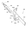
図6乃至図8に示すように、トレッド位置決め装置50は円筒形の筒体51と、該筒体51内にスライド自在に嵌合したシャフト52とからなり、該筒体51の上面に長手方向へ長孔53を開穿するとともに、シャフト52の上面に長手方向へ複数の位置決め孔54,54…を設けて前記長孔53から臨ませてある。長孔53の上方からピン55を挿入して任意の位置決め孔54に差込むことにより、前記筒体51に対するシャフト52のスライド終着位置を決めることができる。また、該トレッド位置決め装置50は、フロントアクスルハウジング20のアウターアクスル20aにボルト締めにて着脱自在に取り付けられている。
【0016】
一方、トレッド固定装置60は、円筒形の筒体61と、該筒体61内にスライド自在に嵌合したシャフト62と、シャフト62の上部に設けた逆L字形のプレート63等からなり、該プレート63の長辺63aはシャフト62と平行に配設され、前記筒体61の上部に一体的に設けられたガイド部64に対してスライド可能に接触し、この長辺63aと直角をなす短辺63bは前記シャフト62の一端面にボルト締めされている。
【0017】
そして、前記ガイド部64に螺子部を有する開口孔65を設けるとともに、プレート63の長辺63aに長手方向に複数の固定孔(ばか孔)66,66…を開穿し、該プレート63がスライドして前記開口孔65の上部に何れか一つの固定孔66が移動したとき、該固定孔66の上方から固定ボルト67を挿入して前記開口孔65に螺合できるように形成してある。尚、とくに前記筒体61の上部にガイド部64を設けず、螺子部を有する開口孔65を直接筒体61に設けるとともに、筒体61の上面部にプレート63の長辺63aをスライド可能に接触させるように形成してもよい。また、該トレッド固定装置60も、フロントアクスルハウジング20のアウターアクスル20aにボルト締めにて着脱自在に取り付けられている。
【0018】
更に、インナーアクスル20bに鍔状のプレート25を固設し、該プレート25の一端部を前記トレッド位置決め装置50のシャフト52の端面に固定するとともに、該プレート25の他端部をトレッド固定装置60のシャフト62の端面に固定してある。従って、インナープレート20bの左右方向への移動に連動して、前記シャフト52とシャフト62が一体的にスライドする。
【0019】
次に、図4乃至図8に従って、トレッド変更手順について更に詳述する。トレッドを変更する場合は、先ず左右のナックルアーム33,33に設けられている係止孔33a,33aにピンなどを挿入し、ナックルアーム33,33の回転を固定した後に、左右何れか一方のタイロッドエンド45を係止具41から弛緩若しくは離脱させる。例えば、左側のインナーアクスル20bを移動する場合は、右側の係止具41のストッパボルト48を取り外し、該係止具41を弛緩して右側のタイロッドエンド45のスライドロッド46をフリーにする。
【0020】
この状態で、前記ステアリングシリンダ36を駆動してピストンロッド39,39を左側へ移動すれば、左側の係止具41に係止した左側のタイロッドエンド45が左方へ押されて、左側のナックルアーム33と一体に左側のインナーアクスル20bが外側へ引き出される。斯くして、前記フロントアクスルハウジング20の左側部分の幅が伸長し、トレッドが拡大される。これとは逆に、ピストンロッド39を右側へ移動すれば、左側のインナーアクスル20bが内側へ引き込まれてフロントアクスルハウジング20の左側部分の幅が短縮し、トレッドが縮小される。
【0021】
続いて、右側のインナーアクスル20bを移動する。この場合は、前述とは反対に、左側の係止具41のストッパボルト48を取り外し、該係止具41を弛緩して左側のタイロッドエンド45のスライドロッド46をフリーにする。この状態で、前記ステアリングシリンダ36を駆動してピストンロッド39,39を左右何れかへ移動すれば、右側の係止具41に係止した右側のタイロッドエンド45が左右どちらかに押されて、右側のナックルアーム33と一体に右側のインナーアクスル20bが押し引きされる。斯くして、前記フロントアクスルハウジング20の右側部分の幅が伸縮し、トレッドが拡大または収縮する。
【0022】
同図に示すように、ピストンロッド39,39の端面とナックルアーム33,33との距離が短くて、タイロッド49を伸縮させる部材の取り付けが困難である場合でも、前記ピストンロッド39の軸心と、タイロッドエンド45のスライドロッド46の軸心とをオフセットしてピストンロッド39とタイロッドエンド上を平行にラップさせ、このラップ部分に伸縮部材(本実施の形態では係止具41とスライドロッド46)を介装することにより、タイロッド49の長さを伸縮することが可能となる。
【0023】
また、左側のトレッドを広げるときは、図7(a)に示すように、例えば前記左側のトレッド位置決め装置50の左から1番目の位置決め孔54にピン55を差し込み、且つ、前記左側のトレッド固定装置60の固定ボルト67を弛緩して取り外す。斯かる状態で、前述したように、左右のナックルアーム33,33の回転を固定して右側のタイロッドエンド45を係止具41から弛緩させ、前記ステアリングシリンダ36の駆動にて左側のインナーアクスル20bを左方に引き出せば、前記トレッド位置決め装置50のシャフト52が筒体51内をスライドして左へ移動するとともに、前記トレッド固定装置60のシャフト62が筒体61内をスライドして左へ移動する。
【0024】
そして、同図(b)に示すように、前記シャフト52に差し込んだピン55が長孔53の左端部に当接したときに、シャフト52がそれ以上左方向へはスライドできなくなり、左側のインナーアクスル20bの移動が停止する。然る後に、前記トレッド固定装置60の固定孔66に固定ボルト67を挿入して開口孔65に螺合すれば、シャフト62のスライドが拘束されてトレッドが固定される。
【0025】
一方、左側のインナーアクスル20bを右方に引き込んでトレッドを狭める場合も、前記シャフト52に差し込んだピン55が長孔53の右端部に当接したときにシャフト52の右方向へのスライドができなくなり、インナーアクスル20bの移動が停止する。尚、右側のトレッドを変更するときは、前述とは対称的に右側のトレッド位置決め装置50と右側のトレッド固定装置60を動作させることにより、右側部分のトレッド位置決めとトレッド固定とを簡単に行うことができる。
【0026】
そして、トレッドの拡張または縮小何れの場合であっても、前記ピン55の差込み位置を変えることによりシャフト52のスライド終着位置が変わり、極めて容易に数段階のトレッド位置決めを行うことができる。また、図示は省略するが、前記トレッド位置決め装置50のシャフト52に設けられている任意の2つの位置決め孔54,54に夫々ピン55,55を差し込んでおくことにより、2段階のトレッドをピン55の差し替えなしで交互に変更することができる。
【0027】
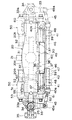
図1及び図6に示すように、前記トレッド位置決め装置50とトレッド固定装置60は、フロントアクスルハウジング20の前後に対向配設され、且つ、フロントアクスルハウジング20の水平面に対して傾斜させてあるため、該フロントアクスルハウジング20の後上方に設置されている運転席13からの目視が可能であり、オペレータが運転席13に着座した状態でトレッドがどの位置に変更されているかを容易に視認できる。また、トレッド変更時に前記ピン55の抜き差しや固定ボルト67を着脱する際も、タイヤ越しではなく斜め後方から目視しながら作業を行うことが可能となり、作業性が向上する。
【0028】
また、前記トレッド位置決め装置50とトレッド固定装置60は、フロントアクスルハウジング20のアウターアクスル20aに着脱自在であるため、トレッド固定型の作業車両とトレッド変更型の作業車両とでアウターアクスル20aを共用化することができる。
【0029】
尚、本発明は、本発明の精神を逸脱しない限り種々の改変を為すことができ、そして、本発明が該改変されたものに及ぶことは当然である。
【0030】
【発明の効果】
本発明は上記一実施の形態に詳述したように、請求項1記載の発明はセンターケース(20a)の左右両端にインナーアクスル(20b,20b)をスライド自在に差し込んで伸縮可能に形成されたアクスルハウジング(20)の左右前後に、トレッド位置決め装置(50,50)とトレッド固定装置(60,60)とを互いに対抗し着脱自在に配設してあるので、アクスルハウジングの形状が一方に偏らず、強度を均一化することができる。また、該トレッド位置決め装置とトレッド固定装置を取り外すことによって、簡単にトレッド固定型とトレッド変更型にすることができる。従って、トレッド固定型とトレッド変更型とでアクスルハウジングを共用することができ、部品の共用化によるコストダウンを図ることができる。更に、上記インナーアクスル(20b,20b)に鍔状のプレート(25,25)を固設し、該プレート(25,25)の一端部を上記トレッド位置決め装置(50,50)のシャフト(52,52)の端面に固定するとともに、該プレート(25,25)の他端部をトレッド固定装置(60,60)のシャフト(62,62)の端面に固定してあるため、インナープレート(20b,20b)の左右方向への移動に連動して、前記シャフト(52)とシャフト(62)が一体的にスライドする。
トレッドの拡張または縮小何れの場合であっても、前記ピン(55)の差込み位置を変えることによりシャフト(52)のスライド終着位置が変わり、極めて容易に数段階のトレッド位置決めを行うことができる。また、前記トレッド位置決め装置(50)のシャフト(52)に設けられている任意の2つの位置決め孔(54,54)に夫々ピン(55,55)を差し込んでおくことにより、2段階のトレッドをピン(55)の差し替えなしで交互に変更することができる。
【0031】
請求項2記載の発明は、伸縮可能に形成されたアクスルハウジングのトレッド変更部を水平面に対して傾斜させ、該トレッド変更部分を運転席から目視可能に配設したことにより、オペレータが運転席に着座した状態でトレッドの変更位置を容易に視認できる。また、トレッド変更時に前記ピン55の抜き差しや固定ボルト67を着脱する際も、タイヤ越しではなく斜め後方から目視しながら作業を行なうことが可能となり、作業性も向上できる等、正に諸種の効果を奏する発明である。
【図面の簡単な説明】
図は本発明の一実施の形態を示すものである。
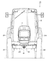
【図1】作業車両の一例であるトラクタの側面図。
【図2】トラクタの正面図。
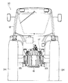
【図3】トラクタの背面図。
【図4】フロントアクスルハウジングの平面図。
【図5】ブラケットとタイロッドエンドの要部斜視図。
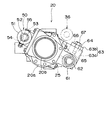
【図6】フロントアクスルハウジングの側面図。
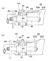
【図7】トレッド位置決め装置とトレッド固定装置の要部を示し、(a)はトレッド収縮時の平面図、(b)はトレッド拡大時の平面図。
【図8】トレッド固定装置の要部を示し、(a)はトレッド収縮時の背面図、(b)はトレッド拡大時の背面図。
【符号の説明】
13 運転席
20 フロントアクスルハウジング
50 トレッド位置決め装置
60 トレッド固定装置[0001]
BACKGROUND OF THE INVENTION
The present invention relates to a tread changing device for a work vehicle, and more particularly to a tread changing device for a work vehicle having an axle housing formed to be extendable and contractible.
[0002]
[Prior art]
In work vehicles used for construction work, agricultural work, etc., the inner axle is slidably inserted into the outer axle (center case) to make the axle housing extendable, and the inner axle is slid according to the work contents. The thing which made it possible to change a tread by doing is known. A tread positioning device for determining the sliding position of the inner axle and a tread fixing device for fixing the inner axle to stop the rotation are integrated with the outer axle.
[0003]
[Problems to be solved by the invention]
In this type of work vehicle tread changing device, since the tread positioning device and the tread fixing device are integrally provided on the outer axle, the outer axle is shared by the normal tread fixing type axle housing and the tread changing type axle housing. However, it was difficult to manufacture the axle housings, and the axle housings had to be formed separately.
[0004]
Therefore, there is a technical problem to be solved in order to share parts between the tread change type axle housing and the tread fixed type axle housing, and the present invention aims to solve this problem. To do.
[0005]
[Means for Solving the Problems]
The present invention has been proposed in order to achieve the above object, and the invention according to claim 1 is capable of extending and contracting by inserting the inner axles (20b, 20b) slidably into the left and right ends of the center case (20a). left and right front and rear of the formed axle housing (20), the tread positioning device (50, 50) and the tread fixing device (60, 60) and against each other removably arranged, the tread positioning device (50, 50 ) Includes a cylindrical body (51, 51) having a long hole ( 53, 53 ) along the axle housing (20) , and slides in the cylindrical body ( 51, 51 ) and the long hole (53, 53). And a shaft (52, 52) having a plurality of positioning holes (54, 54...) Through which the pins (55, 55) are inserted, and the tread fixing device (60, 60) . Is a cylindrical body (61, 61) having an opening hole (65, 65) for inserting the fixing bolt (67, 67) , and slides in the cylindrical body (61, 61) and the opening hole ( 65, 65 ). with inverted L-shaped plates (63, 63) Tsukino a shaft (62, 62) having a plurality of fixing holes for inserting the fixing bolts (67) (66, 66 ...), and, the inner axle (20b , 20b) and a bowl-shaped plate (25, 25) are fixed to each other, and one end of the plate (25, 25) is fixed to the end surface of the shaft (52, 52) of the tread positioning device (50, 50). And a tread changing device for a work vehicle in which the other end of the plate (25, 25) is fixed to the end surface of the shaft (62, 62) of the tread fixing device (60, 60) .
In the invention according to claim 2 , the tread positioning device ( 50, 50 ) and the tread fixing device ( 60, 60) are arranged to be inclined with respect to the horizontal plane of the axle housing (20) , and at least the tread positioning device. The tread changing device for a work vehicle according to claim 1, wherein ( 50, 50) is disposed so as to be visible from the driver's seat (13) .
[0006]
DETAILED DESCRIPTION OF THE INVENTION
Hereinafter, an embodiment of the present invention will be described in detail with reference to the drawings. 1 to 3 show a
[0007]
On the other hand, a
[0008]
FIG. 4 is a plan view of the
[0009]
A
[0010]
[0011]
Then, the
[0012]
As shown in FIG. 4, the
[0013]
Here, the
[0014]
Further, at the left and right ends of the
[0015]
As shown in FIGS. 6 to 8, the
[0016]
On the other hand, the
[0017]
The
[0018]
Further, a flange-shaped
[0019]
Next, the tread changing procedure will be further described in detail with reference to FIGS. When changing the tread, first, pins or the like are inserted into the locking
[0020]
In this state, when the
[0021]
Subsequently, the right
[0022]
As shown in the figure, even when the distance between the end surfaces of the
[0023]
When the left tread is widened, as shown in FIG. 7A, for example, a
[0024]
As shown in FIG. 5B, when the
[0025]
On the other hand, when the left
[0026]
In either case of expansion or contraction of the tread, the slide end position of the
[0027]
As shown in FIGS. 1 and 6, the
[0028]
Since the
[0029]
It should be noted that the present invention can be variously modified without departing from the spirit of the present invention, and the present invention naturally extends to the modified ones.
[0030]
【The invention's effect】
As described in detail in the above embodiment, the present invention is formed to be extendable by inserting inner axles (20b, 20b) slidably into the left and right ends of the center case (20a) . Since the tread positioning device (50, 50) and the tread fixing device (60, 60) are detachably disposed opposite to each other on the left and right sides of the axle housing (20) , the shape of the axle housing is biased to one side. Therefore, the strength can be made uniform. Also, by removing the tread positioning device and the tread fixing device, it is possible to easily make the tread fixing type and the tread changing type. Therefore, the axle housing can be shared by the tread fixing type and the tread changing type, and the cost can be reduced by sharing the parts. Further, a bowl-shaped plate (25, 25) is fixed to the inner axle (20b, 20b), and one end of the plate (25, 25) is attached to the shaft (52, 25) of the tread positioning device (50, 50). 52) and the other end of the plate (25, 25) is fixed to the end surface of the shaft (62, 62) of the tread fixing device (60, 60), so that the inner plate (20b, The shaft (52) and the shaft (62) slide integrally with the movement of 20b) in the left-right direction.
Regardless of whether the tread is expanded or contracted, the slide end position of the shaft (52) is changed by changing the insertion position of the pin (55), so that tread positioning in several steps can be performed very easily. Further, by inserting the pins (55, 55) into arbitrary two positioning holes (54, 54) provided in the shaft (52) of the tread positioning device (50), respectively, a two-stage tread is obtained. The pins (55) can be changed alternately without replacement.
[0031]
According to a second aspect of the present invention, the tread change portion of the axle housing formed to be extendable and tilted is inclined with respect to the horizontal plane, and the tread change portion is disposed so as to be visible from the driver's seat. The tread change position can be easily visually recognized while seated. Also, when inserting and removing the
[Brief description of the drawings]
The figure shows an embodiment of the present invention.
FIG. 1 is a side view of a tractor as an example of a work vehicle.
FIG. 2 is a front view of a tractor.
FIG. 3 is a rear view of the tractor.
FIG. 4 is a plan view of a front axle housing.
FIG. 5 is a perspective view of main parts of a bracket and a tie rod end.
FIG. 6 is a side view of a front axle housing.
7A and 7B show a main part of a tread positioning device and a tread fixing device, where FIG. 7A is a plan view when the tread is contracted, and FIG. 7B is a plan view when the tread is enlarged.
8A and 8B show a main part of the tread fixing device, in which FIG. 8A is a rear view when the tread is contracted, and FIG. 8B is a rear view when the tread is enlarged.
[Explanation of symbols]
13 Driver's
Claims (2)
Priority Applications (1)
| Application Number | Priority Date | Filing Date | Title |
|---|---|---|---|
| JP24499599A JP4013418B2 (en) | 1999-08-31 | 1999-08-31 | Tread changing device for work vehicle |
Applications Claiming Priority (1)
| Application Number | Priority Date | Filing Date | Title |
|---|---|---|---|
| JP24499599A JP4013418B2 (en) | 1999-08-31 | 1999-08-31 | Tread changing device for work vehicle |
Publications (2)
| Publication Number | Publication Date |
|---|---|
| JP2001063306A JP2001063306A (en) | 2001-03-13 |
| JP4013418B2 true JP4013418B2 (en) | 2007-11-28 |
Family
ID=17127028
Family Applications (1)
| Application Number | Title | Priority Date | Filing Date |
|---|---|---|---|
| JP24499599A Expired - Fee Related JP4013418B2 (en) | 1999-08-31 | 1999-08-31 | Tread changing device for work vehicle |
Country Status (1)
| Country | Link |
|---|---|
| JP (1) | JP4013418B2 (en) |
Families Citing this family (1)
| Publication number | Priority date | Publication date | Assignee | Title |
|---|---|---|---|---|
| JP5828512B2 (en) * | 2011-12-02 | 2015-12-09 | Udトラックス株式会社 | Suspension mounting structure |
-
1999
- 1999-08-31 JP JP24499599A patent/JP4013418B2/en not_active Expired - Fee Related
Also Published As
| Publication number | Publication date |
|---|---|
| JP2001063306A (en) | 2001-03-13 |
Similar Documents
| Publication | Publication Date | Title |
|---|---|---|
| KR100268316B1 (en) | Toe angle adjustment mechanism for vehicle wheels | |
| US8839902B1 (en) | Hydraulic motor driven rack and pinion steering assembly | |
| EP3028927B1 (en) | Steering device and vehicle with same | |
| EP2455277B1 (en) | Auxiliary drive | |
| EP1704078B1 (en) | Steering axle for vehicles, in particular for public works vehicles or agricultural tractors | |
| RU52780U1 (en) | STEERING FOR ALL-WHEEL DRIVING VEHICLE | |
| US20070207663A1 (en) | Working machine | |
| JP3698289B2 (en) | Car steering device | |
| JP4013418B2 (en) | Tread changing device for work vehicle | |
| JP2600374Y2 (en) | Rear wheel steering device for four-wheel steering vehicle | |
| JP3891744B2 (en) | Tractor steering device | |
| JPH03182880A (en) | Steering mechanism for tractor | |
| JP2016055804A (en) | Steering device and method for changing driving modes of vehicle | |
| JP4070670B2 (en) | Industrial vehicle | |
| KR102665674B1 (en) | Cylinder for steering system of large vehicle and manufacturing method thereof | |
| CN209739246U (en) | Movable steering mechanism of double-front-wheel vehicle | |
| US20030066374A1 (en) | Intermediate steering column | |
| JP2003094907A (en) | Tread adjusting device of working vehicle | |
| JPH01257669A (en) | Steering device of adjustable tread | |
| JPH08310429A (en) | Steering device for tractor | |
| KR20240047538A (en) | Cylinder for steering system of large vehicle and manufacturing method thereof | |
| JPS62203872A (en) | Power steering device | |
| JPH035173Y2 (en) | ||
| JPH07257413A (en) | Fitting structure for power steering cylinder | |
| EP1547906A1 (en) | Suspension arrangement |
Legal Events
| Date | Code | Title | Description |
|---|---|---|---|
| A621 | Written request for application examination |
Free format text: JAPANESE INTERMEDIATE CODE: A621 Effective date: 20050314 |
|
| A131 | Notification of reasons for refusal |
Free format text: JAPANESE INTERMEDIATE CODE: A131 Effective date: 20070327 |
|
| A977 | Report on retrieval |
Free format text: JAPANESE INTERMEDIATE CODE: A971007 Effective date: 20070330 |
|
| A521 | Written amendment |
Free format text: JAPANESE INTERMEDIATE CODE: A523 Effective date: 20070523 |
|
| TRDD | Decision of grant or rejection written | ||
| A01 | Written decision to grant a patent or to grant a registration (utility model) |
Free format text: JAPANESE INTERMEDIATE CODE: A01 Effective date: 20070821 |
|
| A61 | First payment of annual fees (during grant procedure) |
Free format text: JAPANESE INTERMEDIATE CODE: A61 Effective date: 20070903 |
|
| FPAY | Renewal fee payment (event date is renewal date of database) |
Free format text: PAYMENT UNTIL: 20100921 Year of fee payment: 3 |
|
| R150 | Certificate of patent or registration of utility model |
Free format text: JAPANESE INTERMEDIATE CODE: R150 |
|
| FPAY | Renewal fee payment (event date is renewal date of database) |
Free format text: PAYMENT UNTIL: 20100921 Year of fee payment: 3 |
|
| FPAY | Renewal fee payment (event date is renewal date of database) |
Free format text: PAYMENT UNTIL: 20130921 Year of fee payment: 6 |
|
| LAPS | Cancellation because of no payment of annual fees |