JP4011696B2 - Crane wire rope end fixing device - Google Patents
Crane wire rope end fixing device Download PDFInfo
- Publication number
- JP4011696B2 JP4011696B2 JP30659497A JP30659497A JP4011696B2 JP 4011696 B2 JP4011696 B2 JP 4011696B2 JP 30659497 A JP30659497 A JP 30659497A JP 30659497 A JP30659497 A JP 30659497A JP 4011696 B2 JP4011696 B2 JP 4011696B2
- Authority
- JP
- Japan
- Prior art keywords
- rope
- wire rope
- end fixing
- fitting
- side plate
- Prior art date
- Legal status (The legal status is an assumption and is not a legal conclusion. Google has not performed a legal analysis and makes no representation as to the accuracy of the status listed.)
- Expired - Lifetime
Links
Images


Description
【0001】
【発明の属する技術分野】
この発明は、クレーンにおける起伏自在な伸縮ブーム先端部のグースネック部へワイヤーロープの索端を固定するためのワイヤーロープ索端固定装置に関するものである。
【0002】
【従来の技術】
図3および図4に示す如く、クレーンに用いられている起伏自在な伸縮ブームAは、その先端部にグースネック部1を備えている。グースネック部1は、伸縮ブームAの最先端側ブーム筒の先端部に、当該ブーム筒の下側より下方に延出するようにして取り付けた左右一対の側板2,2、および、これらの側板2,2間に配置した先端滑車3,3で構成している。
【0003】
伸縮ブームAの先端部たるグースネック部1からフックブロック(図示せず)を吊下するためのワイヤーロープ4は、伸縮ブームAの基端側(伸縮ブームAの基端部または伸縮ブームAが起伏自在に取り付けられた基台)に配置したウインチ(図示せず)から、グースネック部1の先端滑車3,3、フックブロックの滑車に順次掛け廻した上で、その索端部をグースネック部1の一方の側板外側にワイヤーロープ索端固定装置Bを介して固定するようにしている。
【0004】
図3および図4には、従来のワイヤーロープ索端固定装置Bを示している。ワイヤーロープ索端固定装置Bは、索端固定具5とロープガイド金具6とで構成されている。前記索端固定具5は、ワイヤーロープ4の索端を固定するためのものであって、グースネック部1の一方の側板2外側であって側面視において前記先端滑車3,3の上方位置に取り付けられている。また、前記ロープガイド金具6は、円弧状のロープ案内面6aを有しており、この案内面6aにより索端固定具5に至るワイヤーロープ4を側面視において先端滑車3,3の外縁に略沿うように案内するようになっており、グースネック部1の一方の側板外側に固定配置している。
【0005】
このような索端固定具5とロープガイド金具6とで構成された従来のワイヤーロープ索端固定装置Bにあっては、伸縮ブームAの倒伏位置から最大起仰位置までの起伏角度域の全域に渡って、ワイヤーロープ4がロープガイド金具6のロープ案内面6aに圧接した状態を維持して索端固定具5に指向されるように構成する必要がある。そのために、伸縮ブームAを倒伏した状態で、前記ロープガイト金具6のロープ案内面6aに沿って案内されるワイヤーロープ4の折り曲げ角度θが、伸縮ブームAの上記起伏角度域と同等あるいはそれより若干大きくなるよう、ロープガイド金具6と索端固定具5との関係位置を設定する必要がある。
【0006】
クレーンにおいては伸縮ブームAの最大起仰角度が70度以上(90度近い)となっているのが常であるから、伸縮ブームAを倒伏した状態で、前記ロープガイト金具6のロープ案内面6aに沿って案内されるワイヤーロープ4の折り曲げ角度θが70度以上となるようにしなければならず、その結果前記索端固定具5は、ロープガイド金具6によって案内されたワイヤーロープ4が伸縮ブームAの伸縮方向に近い方向となるよう配置されている。換言すれば、索端固定具5からのワイヤーロープ4の引き出し方向が、グースネック部1の側板2の幅方向(伸縮ブームAの伸縮軸線に沿う方向)に近い方向となるようにしている。
【0007】
ところで、グースネック部1の側板の幅方向寸法は、グースネック部1がクレーン作業の支障とならないようできるだけ小さな寸法に規制されており、また、索端固定具5は、ワイヤーロープ4の索端を強固に固定するのに充分な長さ(そこから伸びるワイヤーロープの方向に沿う長さ)が必要とされる。
【0008】
【発明が解決しようとする課題】
このため、従来のワイヤーロープ索端固定装置Bにあっては、グースネック部1の側板の幅寸法を必要以上に大きくして索端固定具5の長さ寸法を確保するか、あるいはグースネック部1の側板の幅寸法を大きくせずに、索端固定具5を限られた長さ寸法内でワイヤーロープ4索端を固定できるよう配慮する必要があった。しかしながら前者の場合、グースネック部1が大きくなってクレーン作業に悪影響を与えるという問題があり、また後者の場合、ワイヤーロープ4索端を索端固定具5に強固に固定するのが難しいという問題がある。なお、図3および図4は、後者のように処置した例を示しており、索端固定具5におけるスリーブ部分の長さを短くした上でこれを直接グースネック1の側板2外側に溶接固定した例を示している。
【0009】
本発明は、グースネック部1の側板の限られた幅寸法内に、充分な長さを持った索端固定具を配置することのできるワイヤーロープ索端固定装置Bを提供し、上記した従来技術の問題点を解決しようとするものである。
【0010】
【課題を解決するための手段】
上記した課題を解決するため、本発明に係るクレーンのワイヤーロープ索端固定装置Bは、下記のように構成している。即ち、伸縮ブームA先端部のグースネック部1における両側板2,2間に配置した先端滑車3,3とフックブロック間に掛け廻したワイヤーロープ4の索端を、当該グースネック部1の一方の側板2外側に取り付けられ側面視において当該ワイヤーロープ4を先端滑車3,3の外縁に略沿うように案内する円弧状のロープ案内面6aを有するロープガイド金具6を介して一方の側板2外側に取り付けた索端固定具5に固定することで、伸縮ブームA先端部からフックブロックを吊下げるよう構成したクレーンのワイヤーロープ索端固定装置において、前記索端固定具5を伸縮ブームA倒伏状態で前記ロープガイト金具6のロープ案内面6aに沿って折り曲げられたワイヤーロープ4の折り曲げ角度θが伸縮ブームAの最大起仰角度よりも小さくなるよう一方の側板2外側における上方部分に取り付けると共に、伸縮ブームA起仰状態で前記ロープガイド金具6と索端固定具5間に位置するワイヤーロープ4がロープガイド金具6のロープ案内面6aから離隔した際にロープガイド金具6の反対側から当接して当該ワイヤーロープ4を索端固定具5に案内するロープ案内面7aを有する補助ガイド金具7を一方の側板2外側に取り付けて構成したことを特徴とするクレーンのワイヤーロープ索端固定装置。
【0011】
このように構成したワイヤーロープ索端固定装置は、索端固定具5とロープガイド金具6のみから構成されていた従来のワイヤーロープ索端固定装置に、補助ガイド金具7を追加することで、索端固定具5に案内されるワイヤーロープ4の方向を、グースネック部1の側板2の高さ方向に近い方向とすることができるようにしたものであるから、グースネック部1の側板2の限られた幅寸法内に、充分な長さを持った索端固定具5を配置することができるものである。
【0012】
【発明の実施の形態】
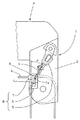
本発明のクレーンのワイヤーロープ索端固定装置Bの実施例を、図1および図2に基づいて説明する。
【0013】
本発明のクレーンのワイヤーロープ索端固定装置Bは、上述した従来のワイヤーロープ索端固定装置Bに比し、グースネック部1の一方の側板2外側に配置した索端固定具5の配置位置を変更したこと、補助ガイド金具7を追加したこと、の二点で相違するものであるから、以下の説明ではこの相違部分について説明し、その他の部分についての説明は上記した従来技術の説明を援用する。
【0014】
まず、相違点の一つである、グースネック部1の一方の側板 2 外側に配置した索端固定具5の配置位置について説明する。索端固定具5は、伸縮ブーム1を水平に倒伏した状態において、前記ロープガイト金具6のロープ案内面6aに沿って折り曲げられたワイヤーロープ4の折り曲げ角度θが、伸縮ブームAの最大起仰角度よりも大幅に小さくなるよう、一方の側板 2 外側における上方部分に取り付けられている。このような配置は、ロープガイド金具6から索端固定具5に至るワイヤーロープ4の方向を、グースネック部1の側板2の高さ方向に近づけることを意味し、幅方向寸法に対して充分大きな高さ寸法を持つグースネック部1の側板2外側に、充分な長さを持った索端固定具5を配置することができるのである。
【0015】
なお、図1および図2では、索端固定具5の長さ寸法を充分大きく取ることができるので、図3および図4に示した従来例のように索端固定具5のスリーブを直接側板2に溶接固定することなく、索端固定具5のスリーブを充分長く構成すると共にその上端に延出したブラケットを、側板2の外側にピン連結したものとしている。
【0016】
次に、相違点の二つ目である補助ガイド金具7の追加について説明する。索端固定具5の配置位置を上記のようにすると、伸縮ブームAを起仰させた時にロープガイド金具6と索端固定具5間に位置するワイヤーロープ4がロープガイド金具6のロープ案内面6aから離脱する。この離脱を規制するために、ロープ案内面7aを有する補助ガイド金具7を取り付けている。この補助ガイド金具7は、ロープ案内面7aが前記ロープガイド金具6と索端固定具5間に位置するワイヤーロープ4がロープガイド金具6のロープ案内面6aから離隔した際にロープガイド金具6の反対側から当接または近接してワイヤーロープ4を索端固定具5に案内するよう、グースネック部1の一方の側板2外側に取り付けている。このように配置した補助ガイド金具7により、伸縮ブームAが起仰した際に前記ロープガイド金具6から離脱しようとするワイヤーロープ4を、補助ガイド金具7のロープ案内面7aで規制して索端固定具5に案内するのである。
【0017】
図1および図2において、8は、グースネック部1の一方の側板2外側に固着したロープガイド金具6と補助ガイド金具7の突出端部を連結する連結部材であって、ワイヤーロープ4の左右方向への逸脱を規制するものである。
【0018】
なお、ロープガイド金具6に求められるワイヤーロープ4の折り曲げ角度θは、従来のそれに比して大幅に小さくなるので、ロープガイド金具6はそれに応じて、例えば図1および図2に示すように変形しても良いこと勿論である。
【0019】
【発明の効果】
この発明に係るクレーンのワイヤーロープ索端固定装置Bは、従来のワイヤーロープ索端固定装置Bの索端固定具5の配置位置を変更すると共に、補助ガイド金具7を追加した簡単な構成でありながら、グースネック部1の側板2の限られた幅寸法内に、充分な長さを持った索端固定具5を配置することができるので、ワイヤーロープ4の索端を確実にグースネック部1に固定できるのである。
【図面の簡単な説明】
【図1】 本発明に係るクレーンのワイヤーロープ索端固定装置を採用した伸縮ブーム先端部の側面図である。
【図2】 図1の前面図である。
【図3】 従来のクレーンのワイヤーロープ索端固定装置を採用した伸縮ブーム先端部の側面図である。
【図4】 図3の前面図である。
【符号の説明】
A;伸縮ブーム、1;グースネック部、2,2;側板、3,3;先端滑車、4;ワイヤーロープ、B;ワイヤーロープ索端固定装置、5;索端固定具、6;ロープガイド金具、 6a;ロープ案内面、7;補助ガイド金具、7a;ロープ案内面、8;連結部材、θ;折り曲げ角度、[0001]
BACKGROUND OF THE INVENTION
The present invention relates to a wire rope rope end fixing device for fixing a rope end of a wire rope to a gooseneck portion at a tip of a telescopic boom that can freely move up and down in a crane.
[0002]
[Prior art]
As shown in FIGS. 3 and 4, the hoistable telescopic boom A used in the crane includes a gooseneck portion 1 at its tip. The gooseneck portion 1 includes a pair of left and
[0003]
The
[0004]
3 and 4 show a conventional wire rope rope end fixing device B. FIG. The wire rope rope end fixing device B includes a
[0005]
In the conventional wire rope rope end fixing device B composed of the rope
[0006]
In a crane, the maximum elevation angle of the telescopic boom A is usually 70 degrees or more (near 90 degrees), so that the telescopic boom A is lying down on the
[0007]
By the way, the width direction dimension of the side plate of the gooseneck part 1 is regulated to a dimension as small as possible so that the gooseneck part 1 does not interfere with the crane work, and the rope
[0008]
[Problems to be solved by the invention]
For this reason, in the conventional wire rope rope end fixing device B, the width dimension of the side plate of the gooseneck part 1 is made larger than necessary to ensure the length dimension of the rope
[0009]
The present invention provides a wire rope nose end fixing device B in which a nose end fixing tool having a sufficient length can be disposed within a limited width dimension of a side plate of the gooseneck portion 1, and the above-described prior art is provided. It is intended to solve the problem.
[0010]
[Means for Solving the Problems]
In order to solve the above-described problem, a wire rope rope end fixing device B for a crane according to the present invention is configured as follows. That is, the end of the
[0011]
Thus constructed wire rope rope end fixing device, by adding to the conventional wire rope rope end fixing device consists only search
[0012]
DETAILED DESCRIPTION OF THE INVENTION
The Example of the wire rope rope end fixing apparatus B of the crane of this invention is described based on FIG. 1 and FIG.
[0013]
The wire rope rope end fixing device B of the crane of the present invention has an arrangement position of the rope
[0014]
First, an arrangement position of the rope
[0015]
1 and 2, since the length of the rope
[0016]
Next, the addition of the auxiliary guide fitting 7 which is the second difference will be described. If the arrangement position of the
[0017]
1 and 2,
[0018]
Since the bending angle θ of the
[0019]
【The invention's effect】
The wire rope rope end fixing device B of the crane according to the present invention has a simple configuration in which the arrangement position of the rope
[Brief description of the drawings]
FIG. 1 is a side view of a distal end portion of a telescopic boom adopting a wire rope rope end fixing device for a crane according to the present invention.
FIG. 2 is a front view of FIG.
FIG. 3 is a side view of a distal end portion of a telescopic boom employing a conventional crane wire rope rope end fixing device.
4 is a front view of FIG. 3. FIG.
[Explanation of symbols]
A: telescopic boom, 1; gooseneck portion, 2, 2; side plate, 3, 3; tip pulley, 4; wire rope, B; wire rope rope end fixing device, 5; rope end fixing device, 6; 6a; rope guide surface, 7; auxiliary guide fitting, 7a; rope guide surface, 8; connecting member, θ: bending angle,
Claims (2)
前記索端固定具5を伸縮ブームA倒伏状態で前記ロープガイト金具6のロープ案内面6aに沿って折り曲げられたワイヤーロープ4の折り曲げ角度θが伸縮ブームAの最大起仰角度よりも小さくなるよう一方の側板2外側における上方部分に取り付けると共に、伸縮ブームA起仰状態で前記ロープガイド金具6と索端固定具5間に位置するワイヤーロープ4がロープガイド金具6のロープ案内面6aから離隔した際にロープガイド金具6の反対側から当接して当該ワイヤーロープ4を索端固定具5に案内するロープ案内面7aを有する補助ガイド金具7を一方の側板2外側に取り付けて構成したことを特徴とするクレーンのワイヤーロープ索端固定装置。 The rope end of the wire rope 4 hung between the end pulleys 3 and 3 and the hook block disposed between the side plates 2 and 2 in the gooseneck portion 1 at the distal end of the telescopic boom A is connected to the outer side of one side plate 2 of the gooseneck portion 1. A rope attached to the outside of one side plate 2 via a rope guide fitting 6 having an arcuate rope guide surface 6a for guiding the wire rope 4 so as to substantially follow the outer edge of the tip pulleys 3, 3 in a side view. In the wire rope rope end fixing device of the crane configured to hang the hook block from the distal end portion of the telescopic boom A by being fixed to the end fixing tool 5,
One to bending angle θ of the Ropugaito fitting 6 wire rope 4 which is bent along the rope guide surface 6a of smaller than the maximum electromotive elevation of the telescopic boom A in the telescopic boom A inclined state the rope end fixing member 5 When the wire rope 4 positioned between the rope guide fitting 6 and the rope end fixing tool 5 is separated from the rope guide surface 6a of the rope guide fitting 6 while being attached to the upper portion outside the side plate 2 Auxiliary guide metal fitting 7 having a rope guide surface 7a for abutting from the opposite side of the rope guide metal fitting 6 to guide the wire rope 4 to the rope end fixing tool 5 is attached to the outside of one side plate 2 and is characterized in that Wire rope rope end fixing device for cranes.
Priority Applications (1)
| Application Number | Priority Date | Filing Date | Title |
|---|---|---|---|
| JP30659497A JP4011696B2 (en) | 1997-10-20 | 1997-10-20 | Crane wire rope end fixing device |
Applications Claiming Priority (1)
| Application Number | Priority Date | Filing Date | Title |
|---|---|---|---|
| JP30659497A JP4011696B2 (en) | 1997-10-20 | 1997-10-20 | Crane wire rope end fixing device |
Publications (2)
| Publication Number | Publication Date |
|---|---|
| JPH11124294A JPH11124294A (en) | 1999-05-11 |
| JP4011696B2 true JP4011696B2 (en) | 2007-11-21 |
Family
ID=17958956
Family Applications (1)
| Application Number | Title | Priority Date | Filing Date |
|---|---|---|---|
| JP30659497A Expired - Lifetime JP4011696B2 (en) | 1997-10-20 | 1997-10-20 | Crane wire rope end fixing device |
Country Status (1)
| Country | Link |
|---|---|
| JP (1) | JP4011696B2 (en) |
Families Citing this family (3)
| Publication number | Priority date | Publication date | Assignee | Title |
|---|---|---|---|---|
| FR2840292B1 (en) | 2002-06-04 | 2004-12-24 | Potain Sa | MOLDING CHANGING DEVICE FOR CRANE |
| KR100607137B1 (en) | 2004-05-28 | 2006-08-01 | 주식회사수산중공업 | Crane having boom head and hook assembly capable of changing easily the number of rope windings |
| CN112881211A (en) * | 2021-01-19 | 2021-06-01 | 青岛海丽雅集团有限公司 | Cable bending test device |
-
1997
- 1997-10-20 JP JP30659497A patent/JP4011696B2/en not_active Expired - Lifetime
Also Published As
| Publication number | Publication date |
|---|---|
| JPH11124294A (en) | 1999-05-11 |
Similar Documents
| Publication | Publication Date | Title |
|---|---|---|
| EP1916219B1 (en) | Boom foot pin attachment and detachment apparatus for construction machine | |
| JP4011696B2 (en) | Crane wire rope end fixing device | |
| JPWO2017119148A1 (en) | Grabber | |
| WO1991005730A1 (en) | An automatic lifting angle adjuster for lifting wire rope | |
| JP2008024419A (en) | Telescopic boom in working machine with boom | |
| JP2005350214A (en) | Cable suspension device for elevator | |
| JP4279709B2 (en) | Lifting lighting system | |
| JP3311313B2 (en) | Detachable mechanism of suspended object in mobile crane | |
| JP3891748B2 (en) | Clamping device | |
| KR20030073127A (en) | Hanger transfer apparatus for black in white | |
| JP4964520B2 (en) | Telescopic cylinder storage device for jib undulation operation of crane truck | |
| JPH10258990A (en) | Wire rope end coupler for mobile crane | |
| JPS6055439B2 (en) | Mounting structure of extension pulley on telescopic boom | |
| JP2507263Y2 (en) | Flexible material guide device used for folding boom | |
| JPH0318471Y2 (en) | ||
| JP2552163Y2 (en) | Hook block storage device for mobile crane with bending boom | |
| JP2528718Y2 (en) | Hook block | |
| JP2528863Y2 (en) | Hook block storage device for mobile crane | |
| JP2003341980A (en) | Bridle feeding device in crane | |
| JPH0417658Y2 (en) | ||
| JP2894587B2 (en) | lighting equipment | |
| JPH0120386Y2 (en) | ||
| JPH0344789Y2 (en) | ||
| JP2756417B2 (en) | Leader raising assist device | |
| JP2579390Y2 (en) | Crane boom |
Legal Events
| Date | Code | Title | Description |
|---|---|---|---|
| A521 | Written amendment |
Free format text: JAPANESE INTERMEDIATE CODE: A523 Effective date: 20040928 |
|
| A621 | Written request for application examination |
Free format text: JAPANESE INTERMEDIATE CODE: A621 Effective date: 20040928 |
|
| A977 | Report on retrieval |
Free format text: JAPANESE INTERMEDIATE CODE: A971007 Effective date: 20070124 |
|
| A131 | Notification of reasons for refusal |
Free format text: JAPANESE INTERMEDIATE CODE: A131 Effective date: 20070508 |
|
| TRDD | Decision of grant or rejection written | ||
| A01 | Written decision to grant a patent or to grant a registration (utility model) |
Free format text: JAPANESE INTERMEDIATE CODE: A01 Effective date: 20070807 |
|
| A61 | First payment of annual fees (during grant procedure) |
Free format text: JAPANESE INTERMEDIATE CODE: A61 Effective date: 20070906 |
|
| R150 | Certificate of patent or registration of utility model |
Free format text: JAPANESE INTERMEDIATE CODE: R150 |
|
| FPAY | Renewal fee payment (event date is renewal date of database) |
Free format text: PAYMENT UNTIL: 20100914 Year of fee payment: 3 |
|
| FPAY | Renewal fee payment (event date is renewal date of database) |
Free format text: PAYMENT UNTIL: 20100914 Year of fee payment: 3 |
|
| FPAY | Renewal fee payment (event date is renewal date of database) |
Free format text: PAYMENT UNTIL: 20110914 Year of fee payment: 4 |
|
| FPAY | Renewal fee payment (event date is renewal date of database) |
Free format text: PAYMENT UNTIL: 20110914 Year of fee payment: 4 |
|
| FPAY | Renewal fee payment (event date is renewal date of database) |
Free format text: PAYMENT UNTIL: 20120914 Year of fee payment: 5 |
|
| FPAY | Renewal fee payment (event date is renewal date of database) |
Free format text: PAYMENT UNTIL: 20130914 Year of fee payment: 6 |
|
| R250 | Receipt of annual fees |
Free format text: JAPANESE INTERMEDIATE CODE: R250 |
|
| EXPY | Cancellation because of completion of term |