JP4009860B2 - Power sliding door opening and closing system - Google Patents
Power sliding door opening and closing system Download PDFInfo
- Publication number
- JP4009860B2 JP4009860B2 JP2003307820A JP2003307820A JP4009860B2 JP 4009860 B2 JP4009860 B2 JP 4009860B2 JP 2003307820 A JP2003307820 A JP 2003307820A JP 2003307820 A JP2003307820 A JP 2003307820A JP 4009860 B2 JP4009860 B2 JP 4009860B2
- Authority
- JP
- Japan
- Prior art keywords
- door opening
- door
- link
- maintenance device
- closing
- Prior art date
- Legal status (The legal status is an assumption and is not a legal conclusion. Google has not performed a legal analysis and makes no representation as to the accuracy of the status listed.)
- Expired - Fee Related
Links
Images


Classifications
-
- B—PERFORMING OPERATIONS; TRANSPORTING
- B60—VEHICLES IN GENERAL
- B60J—WINDOWS, WINDSCREENS, NON-FIXED ROOFS, DOORS, OR SIMILAR DEVICES FOR VEHICLES; REMOVABLE EXTERNAL PROTECTIVE COVERINGS SPECIALLY ADAPTED FOR VEHICLES
- B60J5/00—Doors
- B60J5/04—Doors arranged at the vehicle sides
- B60J5/06—Doors arranged at the vehicle sides slidable; foldable
-
- E—FIXED CONSTRUCTIONS
- E05—LOCKS; KEYS; WINDOW OR DOOR FITTINGS; SAFES
- E05B—LOCKS; ACCESSORIES THEREFOR; HANDCUFFS
- E05B83/00—Vehicle locks specially adapted for particular types of wing or vehicle
- E05B83/36—Locks for passenger or like doors
- E05B83/40—Locks for passenger or like doors for sliding doors
-
- E—FIXED CONSTRUCTIONS
- E05—LOCKS; KEYS; WINDOW OR DOOR FITTINGS; SAFES
- E05F—DEVICES FOR MOVING WINGS INTO OPEN OR CLOSED POSITION; CHECKS FOR WINGS; WING FITTINGS NOT OTHERWISE PROVIDED FOR, CONCERNED WITH THE FUNCTIONING OF THE WING
- E05F15/00—Power-operated mechanisms for wings
- E05F15/60—Power-operated mechanisms for wings using electrical actuators
- E05F15/603—Power-operated mechanisms for wings using electrical actuators using rotary electromotors
- E05F15/632—Power-operated mechanisms for wings using electrical actuators using rotary electromotors for horizontally-sliding wings
- E05F15/643—Power-operated mechanisms for wings using electrical actuators using rotary electromotors for horizontally-sliding wings operated by flexible elongated pulling elements, e.g. belts, chains or cables
- E05F15/646—Power-operated mechanisms for wings using electrical actuators using rotary electromotors for horizontally-sliding wings operated by flexible elongated pulling elements, e.g. belts, chains or cables allowing or involving a secondary movement of the wing, e.g. rotational or transversal
-
- E—FIXED CONSTRUCTIONS
- E05—LOCKS; KEYS; WINDOW OR DOOR FITTINGS; SAFES
- E05B—LOCKS; ACCESSORIES THEREFOR; HANDCUFFS
- E05B81/00—Power-actuated vehicle locks
- E05B81/02—Power-actuated vehicle locks characterised by the type of actuators used
- E05B81/04—Electrical
- E05B81/06—Electrical using rotary motors
-
- E—FIXED CONSTRUCTIONS
- E05—LOCKS; KEYS; WINDOW OR DOOR FITTINGS; SAFES
- E05B—LOCKS; ACCESSORIES THEREFOR; HANDCUFFS
- E05B81/00—Power-actuated vehicle locks
- E05B81/12—Power-actuated vehicle locks characterised by the function or purpose of the powered actuators
- E05B81/14—Power-actuated vehicle locks characterised by the function or purpose of the powered actuators operating on bolt detents, e.g. for unlatching the bolt
-
- E—FIXED CONSTRUCTIONS
- E05—LOCKS; KEYS; WINDOW OR DOOR FITTINGS; SAFES
- E05B—LOCKS; ACCESSORIES THEREFOR; HANDCUFFS
- E05B81/00—Power-actuated vehicle locks
- E05B81/24—Power-actuated vehicle locks characterised by constructional features of the actuator or the power transmission
- E05B81/26—Output elements
- E05B81/28—Linearly reciprocating elements
-
- E—FIXED CONSTRUCTIONS
- E05—LOCKS; KEYS; WINDOW OR DOOR FITTINGS; SAFES
- E05C—BOLTS OR FASTENING DEVICES FOR WINGS, SPECIALLY FOR DOORS OR WINDOWS
- E05C17/00—Devices for holding wings open; Devices for limiting opening of wings or for holding wings open by a movable member extending between frame and wing; Braking devices, stops or buffers, combined therewith
- E05C17/60—Devices for holding wings open; Devices for limiting opening of wings or for holding wings open by a movable member extending between frame and wing; Braking devices, stops or buffers, combined therewith holding sliding wings open
-
- E—FIXED CONSTRUCTIONS
- E05—LOCKS; KEYS; WINDOW OR DOOR FITTINGS; SAFES
- E05Y—INDEXING SCHEME RELATING TO HINGES OR OTHER SUSPENSION DEVICES FOR DOORS, WINDOWS OR WINGS AND DEVICES FOR MOVING WINGS INTO OPEN OR CLOSED POSITION, CHECKS FOR WINGS AND WING FITTINGS NOT OTHERWISE PROVIDED FOR, CONCERNED WITH THE FUNCTIONING OF THE WING
- E05Y2201/00—Constructional elements; Accessories therefore
- E05Y2201/20—Brakes; Disengaging means, e.g. clutches; Holders, e.g. locks; Stops; Accessories therefore
- E05Y2201/218—Holders
- E05Y2201/22—Locks
-
- E—FIXED CONSTRUCTIONS
- E05—LOCKS; KEYS; WINDOW OR DOOR FITTINGS; SAFES
- E05Y—INDEXING SCHEME RELATING TO HINGES OR OTHER SUSPENSION DEVICES FOR DOORS, WINDOWS OR WINGS AND DEVICES FOR MOVING WINGS INTO OPEN OR CLOSED POSITION, CHECKS FOR WINGS AND WING FITTINGS NOT OTHERWISE PROVIDED FOR, CONCERNED WITH THE FUNCTIONING OF THE WING
- E05Y2201/00—Constructional elements; Accessories therefore
- E05Y2201/20—Brakes; Disengaging means, e.g. clutches; Holders, e.g. locks; Stops; Accessories therefore
- E05Y2201/23—Actuation thereof
- E05Y2201/244—Actuation thereof by manual operation
-
- E—FIXED CONSTRUCTIONS
- E05—LOCKS; KEYS; WINDOW OR DOOR FITTINGS; SAFES
- E05Y—INDEXING SCHEME RELATING TO HINGES OR OTHER SUSPENSION DEVICES FOR DOORS, WINDOWS OR WINGS AND DEVICES FOR MOVING WINGS INTO OPEN OR CLOSED POSITION, CHECKS FOR WINGS AND WING FITTINGS NOT OTHERWISE PROVIDED FOR, CONCERNED WITH THE FUNCTIONING OF THE WING
- E05Y2900/00—Application of doors, windows, wings or fittings thereof
- E05Y2900/50—Application of doors, windows, wings or fittings thereof for vehicles
- E05Y2900/53—Application of doors, windows, wings or fittings thereof for vehicles characterised by the type of wing
- E05Y2900/531—Doors
Description
本発明はパワースライディングドア開閉システムに関するものであり、より詳細にはドア開放維持器具を具備したスライディングドア装着の車両にパワースライディングドアシステムが適用される場合、ドアスイッチの作動のみでパワースライディングドアの正常な開閉作動がなされるように、ドア開放維持器具の作動をドアスイッチの操作と連動されるように構成したパワースライディングドア開閉システムに関するものである。 The present invention relates to a power sliding door opening / closing system, and more specifically, when the power sliding door system is applied to a vehicle equipped with a sliding door equipped with a door opening maintenance device, the power sliding door is only operated by a door switch. The present invention relates to a power sliding door opening / closing system configured such that the operation of a door opening maintenance device is interlocked with the operation of a door switch so that a normal opening / closing operation is performed.
周知の通り、バン型自動車等に設置されるスライディングドアは車体の側面に沿って車体の前後方向にスライドさせて開けたり閉めたりする方式であるために、搭乗者の出入が容易で、狭い空間でもドアの開閉が周囲から干渉されない長所がある。 As is well known, sliding doors installed in van-type automobiles, etc., are opened and closed by sliding in the front-rear direction of the car body along the side of the car body. However, there is an advantage that the opening and closing of the door is not interfered by the surroundings.
従来の一般的なスライディングドアには、ドアの閉鎖状態を維持するドア閉鎖維持器具と、ドア閉鎖維持器具に連結されてドア閉鎖維持器具の動作を制御するロッキングコントローラ、ロッキングコントローラに連結されてドアの閉鎖状態を解除するインナーハンドル組合体及びアウトサイドハンドル組立体、ロッキングコントローラに連結されてドアが閉鎖状態でロックされるようにロッキングコントローラを制御するドアロックノブなどが設置される。 The conventional general sliding door includes a door closing maintenance device for maintaining the closed state of the door, a locking controller connected to the door closing maintenance device to control the operation of the door closing maintenance device, and a door connected to the locking controller. An inner handle assembly and an outside handle assembly for releasing the closed state, a door lock knob for connecting the locking controller and controlling the locking controller so that the door is locked in the closed state are installed.
すなわち、開放されたドアを閉じると、ドア閉鎖維持器具によりドアが自動で開放されないように固定され、ドアが閉められた状態でインナーハンドル及びアウトサイドハンドルを操作するとドア閉鎖維持器具が解除されて閉められたドアを開くことができ、ドアロックノブを操作するとドアが閉められた状態でインナーハンドル及びアウトサイドハンドルを操作してもドアが開放されないようになる。 That is, when the opened door is closed, the door is not automatically opened by the door closing maintenance device, and when the inner handle and the outside handle are operated with the door closed, the door closing maintenance device is released. The closed door can be opened, and when the door lock knob is operated, the door is not opened even if the inner handle and the outside handle are operated with the door closed.
このような従来のスライディングドアは、車両が傾斜になった路面に駐車した状態でドアを開くと、ドアが自重によりスライディングしながら閉まって、この時搭乗者自身が閉まるドアにより傷害を受けると言う問題点を有していた。 In such a conventional sliding door, when the door is opened in a state where the vehicle is parked on an inclined road surface, the door is closed while sliding due to its own weight, and at this time, the passenger himself is injured by the closing door. Had problems.
この問題点を解消するために、スライディングドアの開放状態を維持するドア開放維持器具をスライディングドアに設置する方案が提案されて既に広く使用されている。このようなドア開放維持器具を動作制御するためのロッキングコントローラと、インナーハンドル及びアウトサイドハンドルの構造がいろいろ研究されている。 In order to solve this problem, a method of installing a door opening maintenance device for maintaining the sliding door in an open state has been proposed and widely used. Various studies have been conducted on the structure of a locking controller, an inner handle, and an outside handle for controlling the operation of the door opening maintenance tool.
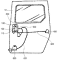
大韓民国公開特許第2002−37464号‘スライディングドアの開閉システム’にはこのようなドア開放維持器具を具備したドア開閉システムの一例が説明されている。図1は従来のスライディングドア開閉システムの一例を示した構成図であり、前記先行技術によるスライディングドア開閉システムの概略的な構成を図示している。 An example of a door opening / closing system provided with such a door opening maintenance device is described in Korean Patent Publication No. 2002-37464, “Sliding Door Opening / Closing System”. FIG. 1 is a configuration diagram illustrating an example of a conventional sliding door opening / closing system, and illustrates a schematic configuration of a sliding door opening / closing system according to the prior art.
図示したシステムは次のような作動構造を有する。
すなわち、スライディングドア10が閉められた状態でインナーハンドル120をドア開放方向に引っ張るか押すと、インナーハンドル120が中立位置でドア開放方向に反らされながらロッキングコントローラ300によりドア閉鎖維持器具400が解除される。スライディングドア10が開放された状態でインナーハンドル120をドア閉鎖方向に押すか引っ張ると、インナーハンドル120が中立位置でドア閉鎖方向に反らされながらロッキングコントローラ300によりドア開放維持器具500が解除される。
The illustrated system has the following operating structure.
That is, when the
図面符号100はインナーハンドル組立体、110はハンドルハウジング、200はドアロックノブ、620及び631はケーブルを各々示す。
一方、最近になって有/無線方式のドアスイッチの操作により自動で開閉作動されるパワースライディングドアがバン型車両のようにスライディングドアを装着した車両に適用される趨勢にある。 On the other hand, recently, power sliding doors that are automatically opened and closed by operation of wired / wireless door switches are being applied to vehicles equipped with sliding doors such as van type vehicles.
このようなパワースライディングドアはモーターやシリンダーのような駆動源と、ケーブルやベルト、ギアのようないろいろな動力伝達手段を利用してドアを自動で開閉させる構造を有し、前記駆動源の動作をドアスイッチと連動して制御するECU(Electrical Control Unit)を具備する。 Such a power sliding door has a structure that automatically opens and closes the door using a driving source such as a motor and a cylinder and various power transmission means such as a cable, a belt, and a gear. ECU (Electrical Control Unit) which controls in conjunction with the door switch.
しかし、前記先行技術によるスライディングドア開閉システムまたはドア開放維持器具が設置された他のいろいろな形態のドア開閉システムは、ドアの開閉が手動式ハンドル操作によりなされる構造を基本として提案されたものである。 However, the sliding door opening / closing system according to the prior art or other various types of door opening / closing systems in which the door opening maintenance device is installed are proposed based on a structure in which the door is opened and closed by a manual handle operation. is there.
このような従来のスライディングドア開閉システムはパワースライディングドアを単純に適用するには適当でない構造を有しており、これによりハンドル操作による手動モードとドアスイッチ操作によるパワーモードがすべて可能なパワースライディングドア開閉システムの開発が切実に要請される実情であった。
本発明は前記のような問題点を勘案して案出したものであり、ドア開放維持器具を具備したスライディングドア装着の車両にパワースライディングドアシステムが適用される場合、ドアスイッチの作動のみでパワースライディングドアの正常的な開閉作動がなされるように、ドア開放維持器具の作動をドアスイッチの操作と連動するように構成したパワースライディングドア開閉システムを提供することをその目的とする。 The present invention has been devised in consideration of the above-described problems. When a power sliding door system is applied to a vehicle equipped with a sliding door equipped with a door opening maintenance device, the power is only operated by a door switch. It is an object of the present invention to provide a power sliding door opening / closing system configured such that the operation of the door opening maintenance device is interlocked with the operation of the door switch so that the sliding door can be normally opened / closed.
前記目的を達成するために本発明は、ハウジング内に設置された多数個のリンクで構成され、ハンドルの操作力をドア閉鎖維持器具またはドア開放維持器具に伝達してその動作を制御し、ケーブルを通じて前記ドア開放維持器具をロックまたは解除状態で動作させるドア開放維持器具用リンクを具備したロッキングコントローラと、前記ドア開放維持器具のロックまたは解除状態を感知する感知手段と、前記ドア開放維持器具用リンクを動作させてドア開放維持器具をロックまたは解除状態で動作させる駆動手段と、ドアスイッチの操作信号を伝送してスライディングドアを開閉させる駆動源の動作を制御し、前記感知手段からドア開放維持器具のロックまたは解除状態に関する感知信号を伝送されて前記駆動手段の動作を制するECUと、を含んで構成され、前記ドア開放維持器具は車体構造物の突出部と回動式で噛み合う噛み合いリンクと、前記噛み合いリンクと突出部の相互噛み合いをロックまたは解除するもののケーブル媒介で前記ドア開放維持器具用リンクに連結されて回動式で作動するロックリンクを含んで構成され、前記感知手段はドア開放維持器具のロックまたは解除状態の可否を前記ロックリンクの回動位置により感知することを特徴とする。 In order to achieve the above object, the present invention comprises a plurality of links installed in a housing, and transmits the operation force of the handle to the door closing maintenance device or the door opening maintenance device to control its operation and to control the cable. A locking controller having a door opening maintenance device link for operating the door opening maintenance device in a locked or unlocked state, sensing means for detecting the lock or release state of the door opening maintenance device, and for the door opening maintenance device Control of the driving means for operating the link to operate the door opening maintenance device in the locked or unlocked state and the driving source for transmitting the door switch operation signal to open and close the sliding door, and maintaining the door opening from the sensing means An ECU for controlling the operation of the driving means by transmitting a sensing signal relating to the locked or unlocked state of the instrument; Comprise configured, the door open maintaining instrument link meshing meshing with the protruding portion and the rotation-type vehicle body structure, the meshing link and the door opening maintained instrument intermeshing cable mediated lock or release ones of the projecting portion And a lock link that is connected to the link link and operates in a pivoting manner, wherein the sensing means senses whether the door opening maintenance device is locked or unlocked based on the rotation position of the lock link. To do.
前記ドア開放維持器具用リンクは、ヒンジ軸を中心にハウジングに回転可能に固定されてケーブル媒介で前記ドア開放維持器具に連結され、前記駆動手段は、前記ドア開放維持器具用リンクに対して前記ヒンジ軸を中心とした回動力を提供するようにその一端部に連結設置されることを特徴とする。 The door opening maintenance instrument link is rotatably fixed to the housing about a hinge axis and connected to the door opening maintenance instrument via a cable, and the driving means is connected to the door opening maintenance instrument link. It is characterized in that it is connected to one end of the hinge shaft so as to provide a rotational force around the hinge shaft.
前記駆動手段はアクチュエータであり、該アクチュエータの駆動側端部には前記ドア開放維持器具用リンクの回動側端部が移動可能な状態で挿入される長孔が形成されることを特徴とする。 The drive means is an actuator, and a long hole is formed in the drive side end of the actuator so that the rotation side end of the door opening maintaining instrument link is inserted in a movable state. .
前記感知手段はマイクロスイッチであり、前記ロックリンクの一側に設置されてその回動位置の変化を接触式で感知することを特徴とする。 The sensing means is a micro switch, and is installed on one side of the lock link and senses a change in its rotational position by a contact method.
前記ECUはドア開放維持状態でドアスイッチからドア閉鎖信号を伝送され、この時に前記感知手段からドア開放維持器具のロックまたは解除状態に関する感知信号を伝送されてロック状態であると判断した場合には、前記駆動手段を動作させてドア開放維持器具を解除状態にし、その後に駆動源を動作させてスライディングドアを閉鎖状態にすることを特徴とする。 When the ECU receives a door closing signal from the door switch in the door open maintenance state and at this time receives a detection signal about the lock or release state of the door opening maintenance device from the sensing means and determines that it is in the locked state The drive means is operated to release the door opening maintenance device, and then the drive source is operated to close the sliding door.
本発明のパワースライディングドア開閉システムは、ドア開放維持器具を具備したスライディングドア装着の車両にパワースライディングドア開閉システムが安定的に適用できるようにして、作動安全性を向上させることができる。 The power sliding door opening / closing system of the present invention can improve the operational safety by enabling the power sliding door opening / closing system to be stably applied to a vehicle equipped with a sliding door equipped with a door opening maintenance device.
以上の本発明の目的と特徴及び長所などは以下の本発明の好適な実施例の説明から明確になるであろう。 The above-mentioned objects, features and advantages of the present invention will become clear from the following description of preferred embodiments of the present invention.
以下添付図面を参照して本発明の望ましい実施例を説明する。
図2は本発明の一実施例によるパワースライディングドア開閉システムの構成図であり、図3は本発明の一実施例によるドア開閉システムのロッキングコントローラの正面図であり、図4(a)及び(b)は本発明の一実施例によるドア開閉システムのドア開放維持器具の斜視図であり、図4(a)はロック解除状態、図4(b)はロック状態を示す状態図、図5(a)ないし(c)は本発明の一実施例によるドア開閉システムのケーブルの操作状態を説明するための作動状態図である。
Hereinafter, preferred embodiments of the present invention will be described with reference to the accompanying drawings.
FIG. 2 is a configuration diagram of a power sliding door opening / closing system according to an embodiment of the present invention, and FIG. 3 is a front view of a locking controller of the door opening / closing system according to an embodiment of the present invention. FIG. 4B is a perspective view of a door opening maintenance device of the door opening and closing system according to the embodiment of the present invention, FIG. 4A is a unlocked state, FIG. 4B is a state diagram showing a locked state, FIG. (a) thru | or (c) is an operation state figure for demonstrating the operation state of the cable of the door opening and closing system by one Example of this invention.
以下、図1の構成要素と同一の構成要素に対しは同一の図面符号を付与して説明する。
本実施例によるロッキングコントローラ300はハウジング310内に設置された多数個のリンクで構成され、ハンドルの操作力をドア閉鎖維持器具400またはドア開放維持器具500に伝達してその動作を制御する機能を遂行するが、特にケーブル631を通じて前記ドア開放維持器具500をロックまたは解除状態で動作させるドア開放維持器具用リンク350を具備する。
Hereinafter, the same components as those in FIG. 1 will be described with the same reference numerals.
The
より詳細に説明すると、前記ロッキングコントローラ300は多数の締結部とガイド穴310a,310b,310cが形成されたハウジング310と、ヒンジ軸Fを中心に回動されるインナーハンドル用リンク320と作動制御用リンク330及びドア閉鎖維持器具用リンク340、ヒンジ軸Mを中心に回動されるドア開放維持器具用リンク350を具備する。
More specifically, the
また、上下方向に往復移動するアウトサイドハンドル用器具360と、ヒンジ軸Kを中心に回動するドアロック用器具370、ヒンジ軸Gを中心に回動するドア開放防止器具380及び、ドアロック用器具370の動作を電気的に制御するアクチュエータ390を具備し、このような各構成要素が相互連動される構造で組立される。
Also, an
このように構成されたロッキングコントローラ300は、運転者の操作により中立位置からドア開放方向またはドア閉鎖方向に選択的な動作がなされるインナーハンドル120またはアウトサイドハンドルにより作動し、ドア閉鎖維持器具400とドア開放維持器具500に各々連結されてこれらの動作を制御する。
The
インナーハンドル用リンク320は、インナーハンドル120のドア開放方向操作時にこれと連動して作動制御用リンク330を通じてドア閉鎖維持器具用リンク340を動作させ、ドア閉鎖維持器具400のロック状態を解除状態にする。インナーハンドル120のドア閉鎖方向操作時には、これと連動してドア開放維持器具用リンク350を動作させ、ドア開放維持器具500のロック状態を解除状態にする。
The
また、アウトサイドハンドル用器具360は、アウトサイドハンドルの操作時にこれと連動して、作動制御用リンク330を通じてドア閉鎖維持器具用リンク340を動作させ、ドア閉鎖維持器具400のロック状態を解除状態にする。これと同時に、ドア開放維持器具用リンク350を動作させてドア開放維持器具500のロック状態を解除状態にする。
In addition, the
特に、スライディングドア10にはドアロックノブ200が具備されるが、ロッキングコントローラ300にはドアロックノブ200のオン操作時にこれと連動して作動制御用リンク330からドア閉鎖維持器具用リンク340への動力伝達を遮断するドアロック用器具370が具備される。
In particular, the sliding
また、ロッキングコントローラ300には取っ手部381aのオン操作時にこれと連動してインナーハンドル用リンク320から作動制御用リンク330への動力伝達を遮断するドア開放防止器具380が具備される。
Further, the
一方、本実施例によるパワースライディングドアは、駆動源であるモーター52と、モーター52からの動力を伝達してスライディングドア10を開閉させる動力伝達手段であるケーブル54と、ドアスイッチ60と連動してモーター52の動作を制御するECU(Electrical Control Unit:50)を具備する。
On the other hand, the power sliding door according to the present embodiment is interlocked with the
モーター52は車両の後方パネルに設置されるが、ドアスイッチ60の操作によりケーブル54を前方または後方側に巻いたり巻き戻したりして、ケーブル54の一側にフリー56を通じて固定連結されたスライディングドア10を開放または閉鎖方向に駆動させる。
The
一方、ドア開放維持器具500は車体構造物700の突出部710と回動式で噛み合う噛み合いリンク511と、噛み合いリンク511と突出部710の相互噛み合いをロックまたは解除するものの、ケーブル631媒介でドア開放維持器具用リンク350に連結され回動式で作動するロックリンク521を含む構成を有する。
On the other hand, the door opening
このようなドア開放維持器具500にはそのロックまたは解除状態を感知するための感知手段が設置される。
すなわち、前記感知手段はドア開放維持器具500のロックまたは解除状態の可否をロックリンク521の回動位置により感知するが、このような感知手段としてはマイクロスイッチ70が使用され、ロックリンク521の一側に設置されてその回動位置の変化を接触式で感知するようになる。
The door
That is, the sensing means senses whether or not the door opening
一方、ドア開放維持器具用リンク350を動作させてドア開放維持器具500をロックまたは解除状態で動作させる駆動手段が設置される。
On the other hand, driving means for operating the door opening maintaining
より詳細に見ると、ドア開放維持器具用リンク350はヒンジ軸Mを中心にハウジング310に回転可能に固定されてケーブル631媒介でドア開放維持器具500に連結されるが、前記駆動手段はドア開放維持器具用リンク350に対してヒンジ軸Mを中心とした回動力を提供するようにその一端部に連結設置される。
In more detail, the door opening
前記駆動手段としてはアクチュエータ80が使用されるが、アクチュエータ80はECU50とワイヤーハーネス81を通じて電気的に連結されており、その駆動側端部82には長孔82aが形成されてドア開放維持器具用リンク350の回動側端部352が移動可能な状態で挿入されるようになる。
As the driving means, an
このような構成下で、ECU50はドアスイッチ60の操作信号を伝送されてスライディングドア10を開閉させるモーター52の動作を制御し、他の一方でマイクロスイッチ70からドア開放維持器具500のロックまたは解除状態に関する感知信号を伝送されてアクチュエータ80の動作を制御するようになる。
Under such a configuration, the
すなわち、ECU50はドア開放維持状態でドアスイッチ60からドア閉鎖信号を伝送され、この時にマイクロスイッチ70からドア開放維持器具500のロックまたは解除状態に関する感知信号を伝送され、ロック状態であると判断した場合にはアクチュエータ80を動作させてドア開放維持器具500を解除状態にする。その後にモーター52を動作させてスライディングドア10を閉鎖状態にする。
That is, the
一方、ドア開放維持器具500が解除状態であると判断した場合にはECU50はアクチュエータ80を動作させず、モーター52を動作させてスライディングドア10を閉鎖状態にする。
On the other hand, when it is determined that the door opening
以下本実施例によるパワースライディングドア開閉システムの作動を説明する。説明の便宜のために、まず手動ハンドル操作時のドア開放維持器具の作動について説明する。 The operation of the power sliding door opening / closing system according to this embodiment will be described below. For convenience of explanation, first, the operation of the door opening maintenance device when operating the manual handle will be described.
スライディングドア10が所定位置まで開かれてドア開放維持器具500が噛み合われた状態で、搭乗者がインナーハンドル120をドア閉鎖方向に引張るか押すと、ヒンジ軸を中心にインナーハンドル120がドア閉鎖方向に回転し、インナーハンドル120のロード連結部(図示せず)に連結されたロード(図示せず)が押される。
When the sliding
これにより、これに連結されたロッキングコントローラ300のロード612が押されながらインナーハンドル用リンク320が回転軸Fを中心に反時計方向(図3参照)に回転し、インナーハンドル用リンク320の他の一側の先端322がドア開放維持器具用リンク350の一側の先端を押し迫ってドア開放維持器具用リンク350が回転軸Mを中心に時計方向に回転する。
As a result, the
この時、ドア開放維持器具用リンク350に連結されたケーブル631のワイヤー631aが引張られるために、このケーブル631のワイヤー631aに連結されたドア開放維持器具500のロックリンク521が反時計方向に回転して噛み合いリンク511とロックリンク521の相互噛み合いが解除され、ドア閉鎖方向へのスライディングドア10の移動が可能になる。
At this time, since the
以後、スライディングドア10がドア閉鎖方向に移動すると、車体構造物700の突出部710に噛み合った噛み合いリンク511がドア開放方向に回転して(図4a参照)、トーションスプリング512の復原力により噛み合いリンク511が噛み合い準備状態を維持するようになる。
Thereafter, when the sliding
ドア閉鎖方向に連続的に移動するスライディングドア10が、ドア閉鎖位置に到達すると、ドア閉鎖維持器具400が噛み合い動作してスライディングドア10が閉鎖状態を維持するようになる。
When the sliding
次にドアスイッチを利用したパワーモードでの作動状態を説明する。手動操作時と同一内容の説明は省略する。 Next, the operation state in the power mode using the door switch will be described. The description of the same content as in manual operation is omitted.
スライディングドア10が所定位置まで開かれてドア開放維持器具500が噛み合った状態で、搭乗者が有線または無線方式のドアスイッチ60を利用してドア閉鎖操作をすると、ロックリンク521の位置を接触式で感知するマイクロスイッチ70がドア開放維持器具500のロックまたは解除状態に対する感知信号をECU50に転送する。
When the sliding
マイクロスイッチ70は図4(a)及び図4(b)に図示した操作状態を有するが、ロック解除状態の場合には図4(a)のようにロックリンク521によって接地された状態になり、ロック状態である場合には図4(b)のようにロックリンク521による押付けが解除されて非接地状態になるために、このような接地の有無による電気的信号をECU50に転送するようになる。
The
マイクロスイッチ70からの感知信号を通じてロック状態であるものとして確認したECU50はアクチュエータ80に電気的信号を転送して、アクチュエータ80の駆動側端部82が下方に移動するように作動させる。
The
このようなアクチュエータ80の動作によりドア開放維持器具用リンク350は回転軸Mを中心に時計方向に回転し、その回動側端部352も下方に移動する。以後、ドア開放維持器具用リンク350に連結されたケーブル631のワイヤー631aが引っ張られてドア開放維持器具500のロックリンク521が解除される過程は前述した通りである。
By such an operation of the
一方、アクチュエータ80の作動は概略2秒ないし3秒程度持続されるように構成することが望ましいが、これはパワースライディングドアシステムの作動前にロックリンク521がロック位置に回動して再びロック状態になることを防止するためである。
On the other hand, it is desirable that the operation of the
以後、ECU50はパワースライディングドアシステムを構成するモーター52が作動するように制御して、スライディングドア10はドア閉鎖方向に移動する。スライディングドア10がドア閉鎖位置に到達すると、ドア閉鎖維持器具400が噛み合い動作してスライディングドア10が閉鎖状態を維持する。
Thereafter, the
一方、アクチュエータ80の駆動側端部82にはドア開放維持器具用リンク350の回動側端部352が移動可能な状態で挿入される長孔82aが形成される。
On the other hand, the drive-
このような形状で両側部材が結合される理由は、ドアスイッチ60の操作によるパワーモード時には図5(a)ないし(b)に図示したように、アクチュエータ80の作動によりドア開放維持器具用リンク350が連動し、ハンドル操作による手動モード時には図5(c)に図示したようにアクチュエータ80が作動しない状態でドア開放維持器具用リンク350のみが長孔82a内で自由に回動可能するためである。
The reason why the both side members are coupled in such a shape is that, in the power mode by the operation of the
以上で説明した本発明はその技術的思想または主要な特徴から抜け出すことがなく他のいろいろな形態で実施されうる。したがって、前記実施例はすべての点で単純な例示に過ぎず、限定的に解釈されてはならない。 The present invention described above can be implemented in various other forms without departing from the technical idea or main features thereof. Therefore, the said Example is only a simple illustration in all the points, and must not be interpreted limitedly.
すなわち、本発明によるドア開閉システムは前記のようにモーターとケーブルにより作動するパワースライディングドアのみに適用されるものではなく、ECUにより駆動源の動作が制御される構造のものならば、その具体的な構造の制限を受けない。 That is, the door opening and closing system according to the present invention is not applied only to the power sliding door operated by the motor and the cable as described above. Not subject to any structural restrictions.
また、本発明によるドア開閉システムは必ず例示された構造のロッキングコントローラまたはドア開放維持器具に適用されるものとして限定されない。すなわち、多少変形された形態のロッキングコントローラに適用されても前記例示されたドア開放維持器具用リンクと類似の機能を有する部材に本実施例によるアクチュエータが連結設置されることができるものであり、ドア開放維持器具の具体的な形態が多少変形されても本実施例によるマイクロスイッチがドア開放維持器具内の適切な位置に設置されるものである。 Further, the door opening and closing system according to the present invention is not limited to being applied to a locking controller or a door opening maintenance device having the exemplified structure. That is, the actuator according to the present embodiment can be connected and installed to a member having a function similar to that of the exemplified link for maintaining the door opening even when applied to a rocking controller having a slightly modified form, Even if the concrete form of the door opening maintenance device is slightly modified, the microswitch according to the present embodiment is installed at an appropriate position in the door opening maintenance device.
また、ECUの制御信号を受けてドア開放維持器具リンクを動作させる駆動手段としては、例示されたアクチュエータ以外に適切な中間部材(例えば、ギア)が連結設置されたモーターのように、同等の機能を有する他の構成要素も使用できる。 In addition, as a driving means for operating the door opening maintenance instrument link in response to a control signal from the ECU, an equivalent function is provided, such as a motor in which an appropriate intermediate member (for example, a gear) is connected and installed in addition to the illustrated actuator. Other components having can also be used.
また、感知手段はロックリンクの回動位置を感知してECUにその感知信号を転送できるものならば、マイクロスイッチ以外の他の方式のスイッチまたはセンサーが使用できる。 In addition, as long as the sensing means can sense the rotational position of the lock link and transfer the sensing signal to the ECU, a switch or sensor of a system other than the microswitch can be used.
10 スライディングドア
50 ECU
52 モーター
60 ドアスイッチ
70 マイクロスイッチ
80 アクチュエータ
120 インナーハンドル
300 ロッキングコントローラ
310 ハウジング
350 ドア開放維持器具用リンク
400 ドア閉鎖維持器具
500 ドア開放維持器具
511 噛み合いリンク
521 ロックリンク
631 ケーブル
700 車体構造物
710 突出部
M ヒンジ軸
10 Sliding
52
Claims (5)
前記ドア開放維持器具のロックまたは解除状態を感知する感知手段と、
前記ドア開放維持器具用リンクを動作させてドア開放維持器具をロックまたは解除状態で動作させる駆動手段と、
ドアスイッチの操作信号を伝送してスライディングドアを開閉させる駆動源の動作を制御し、前記感知手段からドア開放維持器具のロックまたは解除状態に関する感知信号を伝送されて前記駆動手段の動作を制するECUと、
を含んで構成され、
前記ドア開放維持器具は車体構造物の突出部と回動式で噛み合う噛み合いリンクと、前記噛み合いリンクと突出部の相互噛み合いをロックまたは解除するもののケーブル媒介で前記ドア開放維持器具用リンクに連結されて回動式で作動するロックリンクを含んで構成され、前記感知手段はドア開放維持器具のロックまたは解除状態の可否を前記ロックリンクの回動位置により感知することを特徴とするパワースライディングドア開閉システム。 Consists of a number of links installed in the housing, and the operation force of the handle is transmitted to the door closing maintenance device or the door opening maintenance device to control its operation, and the door opening maintenance device is locked or released through the cable. A locking controller having a door opening maintenance appliance link operated by
Sensing means for sensing a locked or unlocked state of the door opening maintenance device;
Drive means for operating the door opening maintenance instrument link to operate the door opening maintenance instrument in a locked or unlocked state;
An operation signal of a door switch is transmitted to control an operation of a driving source that opens and closes the sliding door, and a sensing signal related to a lock or release state of the door opening maintenance device is transmitted from the sensing unit to control the operation of the driving unit. An ECU,
Comprising
The door opening maintaining device is connected to the door opening maintaining device link via a cable that engages and engages with a projecting link of the vehicle body structure in a rotating manner, and locks or releases the meshing between the meshing link and the projecting portion. A power sliding door opening / closing mechanism, wherein the detecting means detects whether the door opening maintaining device is locked or unlocked based on a rotation position of the lock link. system.
Applications Claiming Priority (1)
| Application Number | Priority Date | Filing Date | Title |
|---|---|---|---|
| KR10-2002-0067640A KR100470630B1 (en) | 2002-11-02 | 2002-11-02 | Open and close system of power sliding door |
Publications (2)
| Publication Number | Publication Date |
|---|---|
| JP2004156429A JP2004156429A (en) | 2004-06-03 |
| JP4009860B2 true JP4009860B2 (en) | 2007-11-21 |
Family
ID=32089784
Family Applications (1)
| Application Number | Title | Priority Date | Filing Date |
|---|---|---|---|
| JP2003307820A Expired - Fee Related JP4009860B2 (en) | 2002-11-02 | 2003-08-29 | Power sliding door opening and closing system |
Country Status (4)
| Country | Link |
|---|---|
| US (1) | US20040074148A1 (en) |
| JP (1) | JP4009860B2 (en) |
| KR (1) | KR100470630B1 (en) |
| CN (1) | CN1206437C (en) |
Families Citing this family (17)
| Publication number | Priority date | Publication date | Assignee | Title |
|---|---|---|---|---|
| FR2869264B1 (en) * | 2004-04-23 | 2006-06-23 | Arvinmeritor Light Vehicle Sys | SLIDING DOOR AND VEHICLE WITH SLIDING DOOR |
| DE102004034509A1 (en) * | 2004-07-15 | 2006-02-16 | Brose Schließsysteme GmbH & Co.KG | Sliding door for a motor vehicle |
| US8505241B2 (en) * | 2005-12-08 | 2013-08-13 | Nissan Motor Co., Ltd. | Door lever for controlling a door opening and closing apparatus |
| EP1849940B1 (en) * | 2006-04-27 | 2016-10-12 | Kiekert Aktiengesellschaft | Locking device for a sliding door with means for blocking the door in open position |
| KR100890117B1 (en) * | 2007-08-22 | 2009-03-24 | 현대자동차주식회사 | Inner door handle structure of vehicle using kinesiology |
| KR100951989B1 (en) * | 2008-08-20 | 2010-04-08 | 현대자동차주식회사 | Outside handle unit of vehicle |
| KR101085625B1 (en) | 2009-09-08 | 2011-11-22 | 명 규 박 | Retracting apparatus of a sliding door |
| KR101300129B1 (en) * | 2012-02-27 | 2013-08-26 | 안호경 | Door locking controller and apparatus for automatically operating sliding door of vehicle |
| DE202012104810U1 (en) * | 2012-12-11 | 2013-01-15 | Peter Müller | Closing device for a sliding door |
| KR101382325B1 (en) * | 2013-02-27 | 2014-04-17 | 현대자동차 주식회사 | Sliding door device for motor vehicle |
| KR20170004021U (en) | 2016-05-18 | 2017-11-29 | (주)대한솔루션 | Corner shelf |
| US10465430B2 (en) * | 2017-07-20 | 2019-11-05 | Brose Fahrzeugteile Gmbh & Co. Kommanditgesellschaft, Bamberg | Drive device for a vehicle door |
| DE102017215044B4 (en) * | 2017-08-29 | 2023-11-16 | Lenze Se | Method for changing to a firmware version on an electrical control unit for a drive system, electrical control unit and drive system |
| DE102019134975A1 (en) * | 2019-12-18 | 2021-06-24 | Kiekert Aktiengesellschaft | Drive device for automotive applications |
| CN114687622B (en) * | 2020-12-31 | 2023-08-08 | 比亚迪股份有限公司 | Lock structure for electric sliding door, electric sliding door device and automobile |
| JP2023012836A (en) * | 2021-07-14 | 2023-01-26 | 株式会社アイシン | Lock release control device for opening/closing body |
| CN115012746A (en) * | 2022-06-29 | 2022-09-06 | 东风汽车有限公司东风日产乘用车公司 | Vehicle door electric release control method, device, equipment and storage medium |
Family Cites Families (14)
| Publication number | Priority date | Publication date | Assignee | Title |
|---|---|---|---|---|
| DE3538837A1 (en) * | 1984-11-02 | 1986-05-07 | Ohi Seisakusho Co., Ltd., Yokohama, Kanagawa | OPENING AND CLOSING MECHANISM FOR A SLIDING DOOR |
| JP2827151B2 (en) * | 1994-07-29 | 1998-11-18 | 株式会社大井製作所 | Automatic door opening and closing device |
| GB2315807B (en) * | 1996-07-30 | 1998-09-02 | Mitsui Mining & Smelting Co | A vehicle sliding door assembly for slidable attachment to a vehicle body |
| JP3289882B2 (en) * | 1997-05-22 | 2002-06-10 | 本田技研工業株式会社 | Closing control device for sliding door for vehicle |
| US6125583A (en) * | 1997-08-13 | 2000-10-03 | Atoma International Inc. | Power sliding mini-van door |
| JPH1181769A (en) * | 1997-09-05 | 1999-03-26 | Mitsui Mining & Smelting Co Ltd | Automatic opening and closing device of vehicle slide door |
| JP3734611B2 (en) * | 1997-12-03 | 2006-01-11 | アスモ株式会社 | Automotive sliding door opening and closing device |
| JP2000160930A (en) * | 1998-11-24 | 2000-06-13 | Shiroki Corp | Intermediate stopper control mechanism for sliding door |
| KR100373242B1 (en) * | 2000-11-14 | 2003-02-25 | 기아자동차주식회사 | Locking controller of a sliding door |
| KR100373241B1 (en) * | 2000-11-14 | 2003-02-25 | 기아자동차주식회사 | Open and close system of a sliding door |
| KR100391520B1 (en) * | 2001-01-06 | 2003-07-12 | 기아자동차주식회사 | a controler of sliding door for vehicles |
| JP3931572B2 (en) * | 2001-03-02 | 2007-06-20 | アイシン精機株式会社 | Vehicle door opening / closing operation device |
| JP4008668B2 (en) * | 2001-03-14 | 2007-11-14 | 株式会社大井製作所 | Automatic sliding door |
| US6659515B2 (en) * | 2001-10-30 | 2003-12-09 | Kiekert Ag | Power-closing motor-vehicle door latch |
-
2002
- 2002-11-02 KR KR10-2002-0067640A patent/KR100470630B1/en active IP Right Grant
-
2003
- 2003-08-29 JP JP2003307820A patent/JP4009860B2/en not_active Expired - Fee Related
- 2003-09-19 US US10/665,588 patent/US20040074148A1/en not_active Abandoned
- 2003-10-30 CN CNB2003101030788A patent/CN1206437C/en not_active Expired - Fee Related
Also Published As
| Publication number | Publication date |
|---|---|
| JP2004156429A (en) | 2004-06-03 |
| KR100470630B1 (en) | 2005-02-21 |
| KR20040039543A (en) | 2004-05-12 |
| CN1502772A (en) | 2004-06-09 |
| US20040074148A1 (en) | 2004-04-22 |
| CN1206437C (en) | 2005-06-15 |
Similar Documents
| Publication | Publication Date | Title |
|---|---|---|
| JP4009860B2 (en) | Power sliding door opening and closing system | |
| CN108222713B (en) | Leveling opening control device | |
| US6701671B1 (en) | Child safety slide door apparatus for vehicles | |
| CN110359787B (en) | Automotive door latch with powered opening feature | |
| CN101223323B (en) | Motor vehicle and door lock for a door of a motor vehicle | |
| US7441816B2 (en) | Automotive childproof safety lock control apparatus | |
| US11808064B2 (en) | Latching systems for latching movable panels | |
| JPH09511290A (en) | Vehicle door lock actuator | |
| MXPA01008938A (en) | Power sliding vehicle door. | |
| JP2007321365A (en) | Device for regulating opening motion of door for automobile | |
| JP2002147089A (en) | Lock controller of slide door | |
| US6332634B1 (en) | Remote control device for vehicular slide door apparatus | |
| WO2015182008A1 (en) | Vehicle door opening/closing device | |
| CN114635608A (en) | Door system for a passenger door of a motor vehicle | |
| CN216641762U (en) | Electrically releasable latch system | |
| JP4831794B2 (en) | Back door door opening and closing device | |
| JP4382473B2 (en) | Latch release device for automotive door latch | |
| JP4468745B2 (en) | Door lock system | |
| JP2001311338A (en) | Door lock operating device | |
| CN115341815B (en) | Door latch | |
| KR20070063324A (en) | Door opening device | |
| JP4555731B2 (en) | Door latch device | |
| JP4840016B2 (en) | Clutch mechanism | |
| JP4109610B2 (en) | Door opener | |
| KR100373039B1 (en) | Door opening and shutting system to clutch |
Legal Events
| Date | Code | Title | Description |
|---|---|---|---|
| A131 | Notification of reasons for refusal |
Free format text: JAPANESE INTERMEDIATE CODE: A131 Effective date: 20060725 |
|
| A521 | Request for written amendment filed |
Free format text: JAPANESE INTERMEDIATE CODE: A523 Effective date: 20061019 |
|
| TRDD | Decision of grant or rejection written | ||
| A01 | Written decision to grant a patent or to grant a registration (utility model) |
Free format text: JAPANESE INTERMEDIATE CODE: A01 Effective date: 20070807 |
|
| A61 | First payment of annual fees (during grant procedure) |
Free format text: JAPANESE INTERMEDIATE CODE: A61 Effective date: 20070821 |
|
| R150 | Certificate of patent or registration of utility model |
Ref document number: 4009860 Country of ref document: JP Free format text: JAPANESE INTERMEDIATE CODE: R150 Free format text: JAPANESE INTERMEDIATE CODE: R150 |
|
| FPAY | Renewal fee payment (event date is renewal date of database) |
Free format text: PAYMENT UNTIL: 20100914 Year of fee payment: 3 |
|
| FPAY | Renewal fee payment (event date is renewal date of database) |
Free format text: PAYMENT UNTIL: 20110914 Year of fee payment: 4 |
|
| R250 | Receipt of annual fees |
Free format text: JAPANESE INTERMEDIATE CODE: R250 |
|
| FPAY | Renewal fee payment (event date is renewal date of database) |
Free format text: PAYMENT UNTIL: 20120914 Year of fee payment: 5 |
|
| R250 | Receipt of annual fees |
Free format text: JAPANESE INTERMEDIATE CODE: R250 |
|
| FPAY | Renewal fee payment (event date is renewal date of database) |
Free format text: PAYMENT UNTIL: 20130914 Year of fee payment: 6 |
|
| R250 | Receipt of annual fees |
Free format text: JAPANESE INTERMEDIATE CODE: R250 |
|
| R250 | Receipt of annual fees |
Free format text: JAPANESE INTERMEDIATE CODE: R250 |
|
| R250 | Receipt of annual fees |
Free format text: JAPANESE INTERMEDIATE CODE: R250 |
|
| R250 | Receipt of annual fees |
Free format text: JAPANESE INTERMEDIATE CODE: R250 |
|
| R250 | Receipt of annual fees |
Free format text: JAPANESE INTERMEDIATE CODE: R250 |
|
| R250 | Receipt of annual fees |
Free format text: JAPANESE INTERMEDIATE CODE: R250 |
|
| R250 | Receipt of annual fees |
Free format text: JAPANESE INTERMEDIATE CODE: R250 |
|
| R250 | Receipt of annual fees |
Free format text: JAPANESE INTERMEDIATE CODE: R250 |
|
| R250 | Receipt of annual fees |
Free format text: JAPANESE INTERMEDIATE CODE: R250 |
|
| R250 | Receipt of annual fees |
Free format text: JAPANESE INTERMEDIATE CODE: R250 |
|
| LAPS | Cancellation because of no payment of annual fees |