JP4007907B2 - Separator bolt connector and connection structure - Google Patents
Separator bolt connector and connection structure Download PDFInfo
- Publication number
- JP4007907B2 JP4007907B2 JP2002366209A JP2002366209A JP4007907B2 JP 4007907 B2 JP4007907 B2 JP 4007907B2 JP 2002366209 A JP2002366209 A JP 2002366209A JP 2002366209 A JP2002366209 A JP 2002366209A JP 4007907 B2 JP4007907 B2 JP 4007907B2
- Authority
- JP
- Japan
- Prior art keywords
- reinforcing bar
- bolt
- separator
- separator bolt
- connecting tool
- Prior art date
- Legal status (The legal status is an assumption and is not a legal conclusion. Google has not performed a legal analysis and makes no representation as to the accuracy of the status listed.)
- Expired - Fee Related
Links
Images


Landscapes
- Forms Removed On Construction Sites Or Auxiliary Members Thereof (AREA)
Description
【0001】
【発明の属する技術分野】
この発明は、現場打ちコンクリート構造物の型枠を形成するパネル(コンパネ)を所定位置に保持するのに用いるセパレータボルトをコンクリート構造物に埋設される鉄筋に連結するのに用いるセパレータボルト連結具及び当該連結具を用いた連結構造に関するものである。
【0002】
【従来の技術】
大型のコンクリート工作物は、その構築現場に鉄筋を組立て、その鉄筋を挟んでコンパネを配置し、当該コンパネで囲まれた空間にコンクリートミルクを流し込んで固化させることにより構築される。型枠内にコンクリートミルクを投入したとき、コンパネにはコンクリートの自重による大きな内圧が作用するので、対向するコンパネ相互をセパレータボルトで連結し、更にコンパネの外側に鉄パイプ等を添設配置して、コンパネがコンクリートの内圧で外側に膨らむのを防止している。
【0003】
セパレータボルトは、基本的には連結するコンパネ相互の間隔に応じた長さのものが用いられるのであるが、型枠内には鉄筋が配置されているので、短いセパレータボルトの基端を鉄筋に連結してコンパネを保持することもできる。セパレータボルトと鉄筋とは強固に連結されなければならず、またコンパネには多数のセパレータボルトが取付けられるので、セパレータボルトの鉄筋への連結が簡単かつ速やかにできなければならない。
【0004】
この種のセパレータボルトの鉄筋への連結構造として、セパレータボルトの基端にコ字形に屈折した金具を取付け、この金具に鉄筋を横から挿入して楔を打ち込んで固定するという連結構造が提案されている。
【0005】
また本願の出願人は、特許願2002−5131号において、山形状に折曲げ成形した鉄板に、当該山形の稜線と直交する方向にナットを溶着して当該ナットにセパレータボルトを螺合するか又は当該方向にセパレータボルトを溶着し、山形状鉄板の稜線部のボルト挿通孔に両端を挿通したU字ボルトにより鉄筋を山形状鉄板の裾辺に締結して固定する、セパレータボルトの連結構造を提案している。
【0006】
【発明が解決しようとする課題】
セパレータボルトの連結具を楔で鉄筋に固定する構造は、金具に楔を打ち込むだけなので取付が極めて簡単なように考えられるが、実際には鉄筋は狭い間隔で配置されているので、ハンマーを振るスペースがなく、ハンマーで楔を打ち込むというようなことができないので、楔を確実に打ち込むという作業がかなり面倒である。また、鉄筋は太さの異なる複数種のものが使用されているため、鉄筋の太さに応じて連結具や楔を複数種準備しておかねばならない。前記特許願2002−5131号で提案したものは、一つの連結具で太さの異なる複数種の鉄筋に対応できるが、セパレータボルトの径が異なるものについては、ナットや雌ねじ孔の径の異なる別の連結具を用いなければならない。
【0007】
現場打ちコンクリート型枠の組立には、大量のセパレータボルトが使用されるので、その連結具も一時に準備する必要がある。型枠によって使用される鉄筋の太さやセパレータボルトの径が異なり、更に現場によってはセパレータボルトと連結具とを螺合する場合と溶着する場合とがあり、セパレータボルトを鉄筋と直行する方向に取付ける場合もある。そのため、鉄筋とセパレータボルトとを連結する連結具の種類が多種となり、各種類の連結具を現場の要求に応じて一時に大量に供給できるようにしようとすると、連結具の在庫量が膨大になり、在庫コストが非常に高くなるという問題が生ずる。また、在庫コストを低減するためには、連結具1個当たりの単価が安いことが必要である。
【0008】
この発明は、上記問題に鑑み、少ない部品数と工程数とで安価に製造することができ、かつ1種類の連結具をセパレータボルト径が相違した場合や、連結構造が相違した場合にも汎用的に使用することができるセパレータボルトの連結具及び当該連結具を用いたセパレータボルトと鉄筋との連結構造を得ることを課題としている。
【0009】
【課題を解決するための手段】
上記課題を解決した本願請求項1の発明に係るコンクリート型枠の鉄筋へのセパレータボルト連結具は、一辺又は対向両辺を屈折して添え面22と屈折面19とを形成したL字形又はコ字形の鉄板からなり、その添え面の中央において前記屈折面と直交する方向に押し曲げ成形した添え溝23と、当該添え溝を挟んで対称に配置された当該添え溝と直行する方向に長いボルト挿通用長孔25と、前記屈折面を貫通する径の異なる雌ねじ孔20、21とを備えたものである。
【0010】
上記連結具を用いた本願請求項2のセパレータボルトの連結構造は、上記手段を備えた連結具18の添え溝23に鉄筋3が添設され、当該鉄筋が両端を長孔25に挿通したU字ボルト26で当該連結具に固定され、セパレータボルト6が雌ねじ孔20、21の1個に螺合された構造である。
【0011】
また請求項3のセパレータボルトの連結構造、L字形の請求項1記載の連結具18bの添え溝23に鉄筋3が添設され、当該鉄筋が両端を長孔25に挿通したU字ボルト26により当該連結具に固定され、セパレータボルト6が前記添え溝23の成型時に添え面裏面に生じた畝24に沿って添設されて溶着されている構造である。
【0012】
また請求項4のセパレータボルトの連結構造は、請求項1記載の連結具18の添え溝23に鉄筋3が添設され、当該鉄筋が両端を長孔25に挿通したU字ボルト26により当該連結具に固定され、セパレータボルト6が屈折面19の辺縁29に添設されて溶着されている構造である。
【0013】
【発明の実施の形態】
以下、図面に示す実施例を参照して、この発明の実施形態を説明する。図4はこの発明の手段でコンパネ8を固定した状態を示す概念図である。型枠内に組立てられた鉄筋3の両側にそれぞれ基端を固定したねじ杆(セパレータボルト)6で、当該鉄筋の両側に配置されたコンパネ8が固定されている。セパレータボルト6とコンパネ8の連結部分の構造には各種の構造があるが、図5はその一例を示す図で、セパレータボルト6の先端の雄ねじ部6aに頂部に雌ねじ孔を有するコーンと呼ばれる部材9をねじ込み、このコーンの雌ねじ孔と反対の側に突出している軸足と呼ばれる短いねじ杆10をコンパネ8に設けた貫通孔に挿通し、この軸足に挿通した袋ナット11とコーン9の裾部分でコンパネ8を挟んで固定するという構造である。
【0014】
型枠内に打設したコンクリートが固化したら、袋ナット11を外してコンパネ8を取り外し、更にコーン9を取り外して、その後にできた凹所をモルタルで埋めて、セパレータボルトの先端をコンクリート躯体内に埋め込む。
【0015】
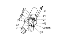
図1は、この発明のセパレータボルト連結具の第1実施例と請求項2の連結構造の実施例とを示した図である。図に示すコ字形の連結具18aは、角丸矩形の鉄板の対向両辺を直角に屈折して側面コの字形に成型したもので、屈折面19の一方には、中央に呼び径8mmのねじ孔20が貫通しており、他方には10mmのねじ孔21が貫通している。添え面22の中央には、屈折面19と直交する方向の添え溝23が形成されている。この溝23は、添え面22にV形の型を押圧して成形しており、塑性変形によって成型している関係上、添え面22の裏面には溝23と平行な方向の畝24(図2参照)が形成される。添え面22には添え溝23と直交する方向に細長いボルト挿通用長孔25が溝23を挟む対称の位置に穿設されている。連結具18(18a及び後述する18b)の鉄板の厚さは、セパレータボルトとして一般に用いられている呼び径8mmと10mmの雄ねじ強度に対応する雌ねじの軸方向長さが確保されるように、図示実施例のものでは6mm厚さのものを用いている。
【0016】
この発明の連結具は上記構造であるため、鉄板の打抜き、折曲げ、押圧というプレス工程と、ねじ孔20、21のタップ加工工程とで製造される1部品のみで構成されるから、比較的安価に提供することができる。また、比較的厚い鉄板を用いることから、強い締結力に耐えるのに十分な強度を持ったものにすることができ、セパレータボルト6と鉄筋3とを強固に連結することができる。
【0017】
図1の実施例の連結構造では、鉄筋3は添え溝23に添設された状態でU字ボルト26により固定されている。U字ボルト26の両端は、連結具の長孔に挿通されて添え面22の裏側からナット27で締結されている。ボルト挿通孔が長孔25となっているため、鉄筋3の太さに対応した脚間隔の異なるU字ボルトを挿通することができ、従って1種類の連結具で鉄筋3の径の変化に対応できる。
【0018】
また、図1の構造では、セパレータボルト6は、連結具の屈折面に設けたねじ孔20、21に螺合して固定される。ねじ孔20、21は、両側の屈折面にそれぞれ異なる径のものが設けてあるので、使用するセパレータボルト6の径に応じたねじ孔を選択して使用することができ、従って1種類の連結具で径の異なる2種類のセパレータボルトに対応することができる。更に図2の実施例に示すように、1個の屈折面に径の異なる2個のねじ孔を設けることもできるので、両方の屈折面にねじ孔を2個ずつ設けてやれば、4種類のセパレータボルトに対応できることになる。
【0019】
図2は、この発明の連結具の第2実施例と請求項3の連結構造の実施例を示した図である。この第2実施例の連結具18bは、角丸矩形の鉄板の一辺のみを直角に屈折して屈折面19を形成したもので、その添え面22には第1実施例と同様な添え溝23とボルト挿通用長孔25とが設けられており、一方、屈折面19には、呼び径8mmと10mmとの径の異なる2つのねじ孔20、21が設けられている。屈折面19上における2つのねじ孔20、21の配置は自由であり、縦方向、横方向、斜方向に自由にに配置でき、互いに径の異なる3個以上のねじ孔を配置することもできる。
【0020】
鉄筋3は、第1実施例と同様に鉄筋3を跨いで両足を長孔25に挿通したU字ボルト26を添え面22の裏側からナット27で締結することにより固定されている。セパレータボルト6は、第1実施例の様に基端をねじ孔20、21に螺合して装着することもできるが、図の実施例では、鉄筋3を位置決めするための添え溝23を成型した際に、添え面22の裏面に生ずる畝24の稜線に沿ってセパレータボルト6の基端を添設して、両側から隅肉溶接28することにより、固定している。この時、畝24とセパレータボルト6の当接部に溶接のための開先が形成された状態となるので、強度の高い溶接を行うことができる。
【0021】
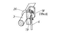
図3は、請求項4の連結構造の実施例を示した図で、図示した連結具18は、第1実施例の連結具であり、この連結具と鉄筋3との固定構造も第1実施例で説明した構造と同じである。図3の構造では、セパレータボルト6の基端を連結具の屈折面19の下辺に添設して両側から隅肉溶接することにより、固定している。
【0022】
この構造の場合、セパレータボルト6は、鉄筋3と直交する方向に延びることとなり、このような方向にセパレータボルトを取付けることは、あまり多くはないが、この発明の連結具によれば、溶接によって容易にセパレータボルト6を鉄筋3と直交する方向に装着することができ、しかも溶接が丸棒(セパレータボルト)を鉄板の辺に沿って溶接するという態様で行われるため、溶接作業が容易で、溶接部の強度も大きくできる。
【0023】
なお以上の実施例の連結具では、ねじ孔20、21をタップ加工により設けているが、ナットをかしめ加工や溶接で屈折部に固定することにより、同様なねじ孔を形成することもできる。
【0024】
【発明の効果】
以上説明したように、この発明によれば、比較的安価に製造可能な1部品からなる連結具を用いて、種々の態様でセパレータボルトを鉄筋に連結することができ、かつ鉄筋の太さやセパレータボルトの太さが変ったときも、1種類の連結具で対応することができるため、連結具の在庫量を低減することができ、連結具の在庫不足によって現場打ちコンクリート型枠の組立工事に遅延を生ずる事態を回避できる。
【図面の簡単な説明】
【図1】この発明の連結具と連結構造の第1実施例を示す斜視図
【図2】この発明の連結具と連結構造の第2実施例を示す斜視図
【図3】この発明の連結構造の第3実施例を示す斜視図
【図4】鉄筋に取付けたセパレータボルトでコンパネを固定する模式的な説明図
【図5】セパレータボルトとコンパネとの固定構造の一例を示す断面側面図
【符号の説明】
3 鉄筋
6 セパレータボルト
18,18a 連結具
19 屈折面
20 ねじ孔
21 ねじ孔
23 添え溝
24 畝
25 長孔
26 U字ボルト
27 ナット
29 辺縁[0001]
BACKGROUND OF THE INVENTION
The present invention relates to a separator bolt connector used for connecting a separator bolt used to hold a panel (panel) forming a formwork of a cast-in-place concrete structure in a predetermined position to a reinforcing bar embedded in the concrete structure, and The present invention relates to a connecting structure using the connecting tool.
[0002]
[Prior art]
A large concrete work is constructed by assembling a reinforcing bar at the construction site, placing a panel with the reinforcing bar in between, pouring concrete milk into a space surrounded by the panel and solidifying it. When concrete milk is poured into the mold, a large internal pressure is applied to the control panel due to its own weight, so the opposing control panels are connected with separator bolts, and an iron pipe or the like is installed outside the control panel. This prevents the control panel from bulging outside due to the internal pressure of the concrete.
[0003]
Separator bolts are basically used with a length corresponding to the distance between the connected control panels. However, since the reinforcing bars are arranged in the mold, the base end of the short separator bolt is used as the reinforcing bar. It can be connected to hold the control panel. The separator bolt and the reinforcing bar must be firmly connected, and since many separator bolts are attached to the panel, the separator bolt must be easily and quickly connected to the reinforcing bar.
[0004]
As a connecting structure of this type of separator bolt to the reinforcing bar, a connecting structure is proposed in which a bracket refracted in a U-shape is attached to the base end of the separator bolt, and the reinforcing bar is inserted from the side and a wedge is driven in and fixed. ing.
[0005]
In addition, in the patent application No. 2002-5131, the applicant of the present application welds a nut to a steel plate bent into a mountain shape in a direction orthogonal to the ridge line of the mountain shape and screws a separator bolt to the nut, or A separator bolt connection structure is proposed in which separator bolts are welded in this direction, and the reinforcing bars are fastened and fixed to the hem side of the mountain-shaped iron plate with U-bolts inserted at both ends into the bolt insertion holes in the ridge line part of the mountain-shaped iron plate is doing.
[0006]
[Problems to be solved by the invention]
The structure that fixes the separator bolt connector to the rebar with a wedge seems to be very easy to install because the wedge is simply driven into the bracket, but in reality the rebar is placed at a narrow interval, so shake the hammer. Since there is no space and it is not possible to drive a wedge with a hammer, the task of driving the wedge securely is quite troublesome. In addition, since a plurality of types of reinforcing bars having different thicknesses are used, a plurality of types of connecting tools and wedges must be prepared according to the thickness of the reinforcing bars. The one proposed in the aforementioned Japanese Patent Application No. 2002-5131 can deal with a plurality of types of reinforcing bars having different thicknesses with a single connecting tool, but those having different separator bolt diameters are different in diameters of nuts and female screw holes. Must be used.
[0007]
Since a large amount of separator bolts are used for assembling the cast-in-place concrete formwork, it is necessary to prepare the connecting tool at a time. The thickness of the reinforcing bar used and the diameter of the separator bolt are different depending on the formwork. Further, depending on the site, the separator bolt and the connecting tool may be screwed or welded, and the separator bolt is attached in a direction perpendicular to the reinforcing bar. In some cases. For this reason, there are many types of connectors that connect reinforcing bars and separator bolts, and if you try to supply a large amount of each type of connector at the same time according to the requirements of the site, the inventory of connectors will be enormous. Therefore, there arises a problem that the inventory cost becomes very high. Moreover, in order to reduce inventory cost, it is necessary that the unit price per connector is low.
[0008]
In view of the above problems, the present invention can be manufactured inexpensively with a small number of parts and processes, and a single type of connector can be used in general when the separator bolt diameter is different or the connection structure is different. It is an object of the present invention to obtain a separator bolt connector that can be used in general and a separator bolt and reinforcing bar connection structure using the connector bolt.
[0009]
[Means for Solving the Problems]
The separator bolt connecting tool to the reinforcing bar of the concrete form according to the invention of claim 1 which has solved the above-mentioned problem is an L-shape or U-shape in which one side or opposite sides are refracted to form a
[0010]
The connecting structure of the separator bolt according to claim 2 using the above connecting tool is such that the reinforcing
[0011]
Further, a reinforcing
[0012]
In addition, the separator bolt connecting structure according to claim 4 has the reinforcing
[0013]
DETAILED DESCRIPTION OF THE INVENTION
Embodiments of the present invention will be described below with reference to examples shown in the drawings. FIG. 4 is a conceptual diagram showing a state in which the
[0014]
When the concrete placed in the mold is solidified, remove the
[0015]
FIG. 1 is a view showing a first embodiment of a separator bolt connector according to the present invention and an embodiment of a connecting structure according to claim 2. The U-shaped
[0016]
Since the connector of the present invention has the above-described structure, it is composed of only one part manufactured by a pressing process of punching, bending, and pressing an iron plate and a tapping process of the screw holes 20 and 21. It can be provided at low cost. Further, since a relatively thick iron plate is used, the steel plate can be strong enough to withstand a strong fastening force, and the
[0017]
In the connection structure of the embodiment of FIG. 1, the reinforcing
[0018]
Moreover, in the structure of FIG. 1, the
[0019]
FIG. 2 is a view showing a second embodiment of the connecting device of the present invention and an embodiment of the connecting structure of
[0020]
In the same manner as in the first embodiment, the reinforcing
[0021]
FIG. 3 is a view showing an embodiment of the connection structure of claim 4. The illustrated
[0022]
In the case of this structure, the
[0023]
In the coupling device of the above embodiment, the screw holes 20 and 21 are provided by tapping, but similar screw holes can be formed by fixing the nut to the refracting portion by caulking or welding.
[0024]
【The invention's effect】
As described above, according to the present invention, it is possible to connect the separator bolt to the reinforcing bar in various manners by using a one-piece connecting tool that can be manufactured at a relatively low cost. When the thickness of the bolt changes, it can be handled with one type of coupler, so the inventory of the coupler can be reduced, and the construction of the cast-in-place concrete formwork can be done due to the lack of coupler inventory. A situation that causes a delay can be avoided.
[Brief description of the drawings]
FIG. 1 is a perspective view showing a first embodiment of a connector and a connecting structure according to the present invention. FIG. 2 is a perspective view showing a second embodiment of the connector and a connecting structure according to the present invention. FIG. 4 is a schematic explanatory view of fixing a panel with a separator bolt attached to a reinforcing bar. FIG. 5 is a cross-sectional side view showing an example of a fixing structure of the separator bolt and the panel. Explanation of symbols]
3
18,18a coupling
19 Refractive surface
20 Screw hole
21 Screw hole
23 Groove
24 畝
25 oblong holes
26 U-bolt
27 Nut
29 border
Claims (4)
Priority Applications (1)
| Application Number | Priority Date | Filing Date | Title |
|---|---|---|---|
| JP2002366209A JP4007907B2 (en) | 2002-12-18 | 2002-12-18 | Separator bolt connector and connection structure |
Applications Claiming Priority (1)
| Application Number | Priority Date | Filing Date | Title |
|---|---|---|---|
| JP2002366209A JP4007907B2 (en) | 2002-12-18 | 2002-12-18 | Separator bolt connector and connection structure |
Publications (2)
| Publication Number | Publication Date |
|---|---|
| JP2004197391A JP2004197391A (en) | 2004-07-15 |
| JP4007907B2 true JP4007907B2 (en) | 2007-11-14 |
Family
ID=32763480
Family Applications (1)
| Application Number | Title | Priority Date | Filing Date |
|---|---|---|---|
| JP2002366209A Expired - Fee Related JP4007907B2 (en) | 2002-12-18 | 2002-12-18 | Separator bolt connector and connection structure |
Country Status (1)
| Country | Link |
|---|---|
| JP (1) | JP4007907B2 (en) |
-
2002
- 2002-12-18 JP JP2002366209A patent/JP4007907B2/en not_active Expired - Fee Related
Also Published As
| Publication number | Publication date |
|---|---|
| JP2004197391A (en) | 2004-07-15 |
Similar Documents
| Publication | Publication Date | Title |
|---|---|---|
| JP2008075251A (en) | Method and structure for joining precast reinforced concrete beam members together | |
| JP5213249B2 (en) | Pile head structure of precast concrete pile and pile head formation method | |
| JP5035984B2 (en) | Joint structure of precast floor slab and beam | |
| JP4007907B2 (en) | Separator bolt connector and connection structure | |
| KR20070027431A (en) | A fastener for fixing a reinforcing bar assembly, a mold panel, and a ceiling panel by spot welding | |
| JPH11323945A (en) | Connecting structure of slope lining precast concrete block | |
| JP4842093B2 (en) | Flat plate construction method | |
| JP4455702B2 (en) | Fitting and its connection method | |
| JP2875776B2 (en) | Construction method of L-shaped retaining wall corner | |
| JP2008163697A (en) | Form structure | |
| JP2904554B2 (en) | Joint structure of block structure for foundation construction | |
| JP6801912B1 (en) | Residual joint formwork and construction method for concrete structures | |
| JP5442336B2 (en) | Joint structure of reinforced concrete beam and steel beam | |
| JP2004183220A (en) | Pile head joint structure, pile head joint hard ware and its construction method | |
| JP4216675B2 (en) | Anchor bolt holder for foundation | |
| JP3068789B2 (en) | PC foundation beam members | |
| JP4574080B2 (en) | Welding brackets for couplers for reinforcing bars for steel pipe piles | |
| KR102004130B1 (en) | Supporting unit of girder panel | |
| JP7324507B2 (en) | Concrete products and their connecting fittings | |
| JP4833866B2 (en) | Separator mounting bracket | |
| JP3103998U (en) | Reinforcing material holder for pressure welding | |
| JP2006299715A (en) | Separator mounting fixture, fastener for separator mounting fixture and separator mounting structure | |
| JP4238169B2 (en) | Formwork device and formwork fixing parts | |
| JP2003201717A (en) | Connector for prefabricated block for civil-engineering construction structure | |
| JPH1150528A (en) | Method for joining reinforced concrete column with beam |
Legal Events
| Date | Code | Title | Description |
|---|---|---|---|
| A621 | Written request for application examination |
Free format text: JAPANESE INTERMEDIATE CODE: A621 Effective date: 20051024 |
|
| A977 | Report on retrieval |
Free format text: JAPANESE INTERMEDIATE CODE: A971007 Effective date: 20070703 |
|
| TRDD | Decision of grant or rejection written | ||
| A01 | Written decision to grant a patent or to grant a registration (utility model) |
Free format text: JAPANESE INTERMEDIATE CODE: A01 Effective date: 20070710 |
|
| A61 | First payment of annual fees (during grant procedure) |
Free format text: JAPANESE INTERMEDIATE CODE: A61 Effective date: 20070828 |
|
| FPAY | Renewal fee payment (event date is renewal date of database) |
Free format text: PAYMENT UNTIL: 20100907 Year of fee payment: 3 |
|
| R150 | Certificate of patent or registration of utility model |
Free format text: JAPANESE INTERMEDIATE CODE: R150 |
|
| FPAY | Renewal fee payment (event date is renewal date of database) |
Free format text: PAYMENT UNTIL: 20110907 Year of fee payment: 4 |
|
| FPAY | Renewal fee payment (event date is renewal date of database) |
Free format text: PAYMENT UNTIL: 20120907 Year of fee payment: 5 |
|
| FPAY | Renewal fee payment (event date is renewal date of database) |
Free format text: PAYMENT UNTIL: 20130907 Year of fee payment: 6 |
|
| R250 | Receipt of annual fees |
Free format text: JAPANESE INTERMEDIATE CODE: R250 |
|
| R250 | Receipt of annual fees |
Free format text: JAPANESE INTERMEDIATE CODE: R250 |
|
| R250 | Receipt of annual fees |
Free format text: JAPANESE INTERMEDIATE CODE: R250 |
|
| LAPS | Cancellation because of no payment of annual fees |