JP4004732B2 - Cleaning device - Google Patents
Cleaning device Download PDFInfo
- Publication number
- JP4004732B2 JP4004732B2 JP2000404020A JP2000404020A JP4004732B2 JP 4004732 B2 JP4004732 B2 JP 4004732B2 JP 2000404020 A JP2000404020 A JP 2000404020A JP 2000404020 A JP2000404020 A JP 2000404020A JP 4004732 B2 JP4004732 B2 JP 4004732B2
- Authority
- JP
- Japan
- Prior art keywords
- water tank
- cleaned
- water
- net
- isolation chamber
- Prior art date
- Legal status (The legal status is an assumption and is not a legal conclusion. Google has not performed a legal analysis and makes no representation as to the accuracy of the status listed.)
- Expired - Fee Related
Links
Images


Description
【0001】
【発明の属する技術分野】
本発明は水洗式の主に食品素材を洗浄する装置に関する。なお当該明細書において記載する『水』とは、上位概念では洗浄に適する液全体を指し、それは時に僅かに加熱したものでもある。
【0002】
【発明が解決しようとする課題】
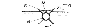
公知の、この種自動式洗浄装置は図2に示すごとく、上面開口型のやや長手の水槽10を基本構成とする。前記水槽の一方の端15において、槽外から槽内に向け矢印11のごとくジエット水流を噴出する一方、敷設パイプ12の周面から吹き出る圧搾空気を槽底面13に形成した無数の小さい穴から排出して気泡化14させる。そこで前記水槽10の一方の端15において同水槽内に適当数の野菜を投入すると、これら各野菜は、前記ジエット水流11によって回転すると共に、同ジエット水流圧11及び各気泡14の破壊圧それぞれの衝撃で、表面付着の塵や埃などを洗い落しながら矢印11の方向に移動し、最終的には水槽他端16の搬出コンベヤ17でもって槽外に排除する仕組みになっている。一方前記水槽の両側壁間に架設する回転軸18、19は、図3に示すごとくその軸線に沿って形成する多数のベーン20を回転させ、水面に浮揚する塵を中空軸18に形成した吸い込み穴22から、水と一体に軸外に流出させるのである。
【0003】
洗浄に用いる食品素材としては、らっきょのような小さな球根から、大きい物では白菜、大根のような、主に野菜類である。これら野菜に付着する土は現地で洗い落され流通するので、殆ど土砂除去の洗浄に用いることは少ないが、野菜の窪み、或いは葉の間に石ころ、糸屑など除去に多く使用することが多い。昨今特に、外国から輸入する漬物用塩漬け野菜の塩抜きにこの種洗浄装置を使用する頻度が高いが、輸入野菜は国内野菜に比べ、毛髪、昆虫、木片、紐くずの付着率が高く、従来のこの種装置ではこれら塵の除去も信頼できないので、結局のところ手作業による塵除去に頼らなければならない、という問題がある。
【0004】
【その解決手段】
本発明は、塵除去洗浄のより完全化及び能率化を図る目的のため、水槽内に設定レベルまで貯えた貯留水に向け、同水槽の一端でジエット水流を噴射すると共に、その余剰水量を同水槽の他端でオーバフオローして一定方向への流れを形成する一方、前記水槽一端の底面から無数の気泡を発生し、前記ジエット水流の圧力衝撃と、前記気泡の破壊衝撃とにより、前記貯留水内の被洗浄物を洗浄しながら、該被洗浄物を前記流れの下流に設置する搬出コンベヤに向けて移動させる洗浄機において、前記水槽におけるジエット水流噴射領域を隔離する粗目ネットの上端を前記貯流水よりも高く配置し、前記の粗目ネットで仕切った隔離室で前記被洗浄物を一次的に停留洗浄しながら、同被包装物から分離する塵を前記粗目ネットを通して水槽他端に排除する一方、前記搬出コンベヤの前面に配置した細目ネットにより上流から排除される前記塵をキヤッチし、その後の前記両ネットの前記貯溜水面上への退避により、前記被包装物を前記搬出コンベヤでもって前記水槽外に搬出する構成する。
【0005】
前記構成では、粗目ネットを前記水槽内に沈めることにより、前記粗目ネットで仕切る隔離室が形成されるので、被洗浄物は前記の隔離室に必然的に止められ、所定時間だけ停留洗浄を受けるので塵除去の効果が上がる。前記の粗目ネットとは、被洗浄物は通過しないが塵は通過可能なメッシュ値を指し、洗浄の間、被洗浄物から剥離する塵は前記ネットを通過して下流で槽外にオーバフオローする。この場合、下流の搬出コンベヤの前面に配置した細目ネットは、上流から流下する前記塵をキヤッチし、その後の前記両ネットの前記貯溜水面上への退避により、前記被包装物を前記搬出コンベヤでもって前記水槽外に搬出する。前記細目ネットにより予め麈をキヤッチして搬出コンベヤへの麈の付着を防止するので、同コンベヤにより槽外に運び出される既洗浄物への塵の再付着を防止できのである。なお当該明細書に記載する『ネット』は学術的には勿論網であるが、例えば『すのこ』など同等効果のある網類似体を、ネットとして請求するものである。
【0007】
【発明の実施形態】
本発明の実施例は、図2における水槽10に粗目ネット30を開閉自在に装着する手段を装備する。該手段は図1及び図4に示すごとく水槽10の内面両側の壁面それぞれに溝型のガイド31を設置し、前記粗目ネット30はこれら両ガイド31をスライドして上下動自在である。前記ネット30の枠上縁に連結する一対のワイヤー32をそれぞれ滑車33を介し、フレーム34に設置するリール35に係合するので、前記フレーム34に設置したモータ36で前記リール35を正逆転する結果、一方向の回転でもって前記粗目ネット30は重量ブロック37の荷重を借りて水槽10内を閉鎖し、所定容積の隔離室38を形成する。
【0008】
図5に示すごとく水槽10両側の空気パイプ40はそれぞれ多数の自在ノズル41を備え、これら各ノズル41による噴射方向は、図2において既に説明したように基本的には矢印11方向ではあるが、僅かに上に、また下に、さらに前、後ろと無秩序の方向に設定するので、隔離室38内部において貯留水に複雑な乱流が発生して被洗浄物を撹乱させ、ジエット水流圧11と、底から沸き上がる気泡破壊圧との相乗作用で、被洗浄物に付着する塵は効率よく除去され且つ矢印43のごとく粗目ネット30を通過して下流に運び出される。
【0009】
図6及び図7に示すごとく、搬送コンベヤ17の前面に、フレーム45に対し軸棒46を支点に上下に開閉する細目ネット47を設置する。この軸棒46の一端に固定するギヤー48と、図4におけるモータ36の軸に固定するギヤー39とをエンドレスチェンを介して連結し、かかる連結による機械的連動手段を形成する。手動スイッチ70でモータ36を操作すると、粗目ネット30の開閉動作と、細目ネット47の開閉動作とは同期する。隔離室38での被洗浄物の洗浄時、粗目ネット30を通過する各塵は下流の細目ネット47でキヤッチすることができる。細目ネット47両側の隙間を無くすために水槽両側の壁には起毛体71を設置している。その後の粗目ネット30及び細目ネットとの同期開放によって、既洗浄物を搬出コンベヤ17で自動運出することができるのである。
【図面の簡単な説明】
【図1】 水槽の一部断面図
【図2】 前図の全体図
【図3】 塵除去手段の断面図
【図4】 図1のIV−IV線に沿った断面図
【図5】 前図の平面図
【図6】 図2における一部の断面図
【図7】 前図のVII−VII線における断面図
【符号の説明】
10…水槽
11…ジエット水流
17…搬出コンベヤ
18…塵除去用の回転軸
30…粗目ネット
31…ガイド
32…ワイヤー
35…リール
36…モータ
37…重量ブロック
38…隔離室
41…自在ノズル
47…細目ネット
39、48…機械的連動手段[0001]
BACKGROUND OF THE INVENTION
The present invention relates to a water-washing type apparatus mainly for cleaning food materials. In the specification, “water” refers to the whole liquid suitable for cleaning in the superordinate concept, and it is sometimes heated slightly.
[0002]
[Problems to be solved by the invention]
As shown in FIG. 2, this known automatic cleaning apparatus has a basic structure of a slightly
[0003]
Food materials used for washing are mainly vegetables such as Chinese cabbage and radish from small bulbs such as raccoon. Since the soil adhering to these vegetables is washed off and distributed locally, it is rarely used for washing to remove earth and sand, but is often used for removing stones, lint, etc. between vegetable depressions or leaves. . Recently, this kind of washing device is frequently used for salting of salted vegetables for pickles imported from abroad. However, imported vegetables have a higher adherence rate to hair, insects, wood chips and string waste than conventional vegetables. This type of device is also unreliable for removing these dusts, so there is a problem that after all, it is necessary to rely on manual dust removal.
[0004]
[Solution]
The present invention injects a jet water flow at one end of the water tank toward the stored water stored up to a set level in the water tank and aims to make the excess water amount the same for the purpose of more complete and efficient dust removal cleaning. While overflowing at the other end of the water tank to form a flow in a certain direction, innumerable bubbles are generated from the bottom surface of the one end of the water tank, and the reservoir is caused by the pressure impact of the jet water flow and the breaking impact of the bubbles. In the washer that moves the object to be cleaned toward the carry-out conveyor installed downstream of the flow while cleaning the object to be cleaned in the water, the upper end of the coarse net that isolates the jet water jet region in the water tank is Disposed higher than the stored water and temporarily stops and cleans the object to be cleaned in an isolation chamber partitioned by the coarse net, while separating the dust separated from the packaged object through the coarse net and the other end of the water tank. On the other hand, the dust to be removed from the upstream by the fine nets arranged on the front surface of the carry-out conveyor is blocked, and then the nets are retreated onto the storage water surface by the both nets so that the packaged goods are removed by the carry-out conveyor. Therefore, it is configured to be carried out of the water tank.
[0005]
In the above configuration, an isolation chamber partitioned by the coarse net is formed by sinking the coarse net in the water tank, so that an object to be cleaned is necessarily stopped in the isolation chamber and subjected to stationary cleaning for a predetermined time. As a result, the dust removal effect is improved. The coarse net refers to a mesh value through which an object to be cleaned does not pass but dust can pass. During cleaning, dust that peels off the object to be cleaned passes through the net and overflows downstream outside the tank. . In this case, the fine net arranged on the front surface of the downstream carry-out conveyor is used to catch the dust flowing down from the upstream, and then the both nets are evacuated onto the storage water surface so that the packaged goods are moved by the carry-out conveyor. Therefore, it is carried out of the water tank. Since the fine net is used to catch the soot in advance to prevent the soot from adhering to the carry-out conveyor, it is possible to prevent the dust from re-adhering to the already cleaned objects carried out of the tank by the conveyor. The “net” described in this specification is of course a net in the academic sense, but for example, a net analog having an equivalent effect such as “Sunoko” is claimed as the net.
[0007]
DETAILED DESCRIPTION OF THE INVENTION
The embodiment of the present invention is equipped with means for attaching the
[0008]
As shown in FIG. 5, the
[0009]
As shown in FIGS. 6 and 7, a
[Brief description of the drawings]
1 is a partial cross-sectional view of a water tank. FIG. 2 is an overall view of the previous figure. FIG. 3 is a cross-sectional view of dust removing means. FIG. 4 is a cross-sectional view taken along line IV-IV in FIG. FIG. 6 is a partial cross-sectional view of FIG. 2. FIG. 7 is a cross-sectional view taken along the line VII-VII of the previous figure.
DESCRIPTION OF
Claims (2)
前記隔離室の隔離壁を粗目ネットにより形成すると共に、該粗目ネットの上端を前記貯留水よりも高く配置する一方、前記隔離室内において前記粗目ネットに向けて噴射するジェット水流に加えて、他のジェット水流を噴射する各ノズルの方向を、僅かに上に、また下に、さらに前、後ろと無秩序の方向に向けると共に、隔離室における複雑な乱流でもって前記被洗浄物を洗浄して同被洗浄物から分離する塵を、前記粗目ネットを通して水槽他端に排除したあと、同塵を、前記搬出コンベヤの前面に配置した細目ネットによってキャッチし、その後の前記両ネットの前記貯溜水面上への退避により、前記隔離室から流出する被洗浄物を、前記搬出コンベヤでもって前記水槽外に搬出する構成の洗浄装置。In an isolation chamber formed at one end of a water tank for storing a set level of stored water, the object to be cleaned is washed with a jet water stream to be jetted and countless bubbles generated from the bottom surface of the water tank, and the excess water amount is separated from that of the water tank. In the cleaning apparatus that moves the object to be cleaned toward the carry-out conveyor at the other end of the water tank, while over-following at the end to form a flow in a fixed direction,
The isolation wall of the isolation chamber is formed by a coarse net, and the upper end of the coarse net is arranged higher than the stored water, while in addition to the jet water flow jetted toward the coarse net in the isolation chamber, The direction of each nozzle that injects the jet water flow is slightly upward, downward, forward, backward, and chaotic, and the object to be cleaned is cleaned with complicated turbulence in the isolation chamber. After the dust separated from the object to be cleaned is removed to the other end of the water tank through the coarse net, the dust is caught by a fine net arranged on the front surface of the carry-out conveyor, and then onto the storage water surface of both the nets. A cleaning device having a configuration in which an object to be cleaned that flows out of the isolation chamber is carried out of the water tank by the carry-out conveyor.
Priority Applications (1)
| Application Number | Priority Date | Filing Date | Title |
|---|---|---|---|
| JP2000404020A JP4004732B2 (en) | 2000-12-08 | 2000-12-08 | Cleaning device |
Applications Claiming Priority (1)
| Application Number | Priority Date | Filing Date | Title |
|---|---|---|---|
| JP2000404020A JP4004732B2 (en) | 2000-12-08 | 2000-12-08 | Cleaning device |
Publications (3)
| Publication Number | Publication Date |
|---|---|
| JP2002177899A JP2002177899A (en) | 2002-06-25 |
| JP2002177899A5 JP2002177899A5 (en) | 2004-12-24 |
| JP4004732B2 true JP4004732B2 (en) | 2007-11-07 |
Family
ID=18868039
Family Applications (1)
| Application Number | Title | Priority Date | Filing Date |
|---|---|---|---|
| JP2000404020A Expired - Fee Related JP4004732B2 (en) | 2000-12-08 | 2000-12-08 | Cleaning device |
Country Status (1)
| Country | Link |
|---|---|
| JP (1) | JP4004732B2 (en) |
Cited By (1)
| Publication number | Priority date | Publication date | Assignee | Title |
|---|---|---|---|---|
| CN104550108A (en) * | 2014-12-11 | 2015-04-29 | 昆明理工大学 | Pseudo-ginseng cleaning machine |
Families Citing this family (8)
| Publication number | Priority date | Publication date | Assignee | Title |
|---|---|---|---|---|
| KR200449276Y1 (en) * | 2008-03-31 | 2010-06-28 | 주식회사 대신종합주방기구 | Machine for washing foods |
| CN103494312B (en) * | 2013-09-26 | 2016-06-01 | 广东水利电力职业技术学院 | Tangerine class fruit disleave device |
| CN107411136A (en) * | 2017-04-21 | 2017-12-01 | 广州华夏职业学院 | A kind of portable banana cleaning machine |
| CN108113021B (en) * | 2017-11-10 | 2020-11-06 | 广西融水县福融贝江源农业发展有限公司 | Vegetable processing and cleaning device |
| CN112958538A (en) * | 2021-03-29 | 2021-06-15 | 安徽采林间食品有限公司 | Dry material cleaning and conveying device for food processing |
| CN114145480A (en) * | 2021-12-08 | 2022-03-08 | 新宁县润杰农业开发有限公司 | Navel orange processing preprocessing device |
| CN114871238B (en) * | 2022-04-29 | 2023-08-08 | 常州裕能石英科技有限公司 | Waste recycling device for machining and working method thereof |
| CN117397827B (en) * | 2023-11-07 | 2024-03-26 | 兴化市联富食品有限公司 | Multifunctional fruit and vegetable processing device |
-
2000
- 2000-12-08 JP JP2000404020A patent/JP4004732B2/en not_active Expired - Fee Related
Cited By (2)
| Publication number | Priority date | Publication date | Assignee | Title |
|---|---|---|---|---|
| CN104550108A (en) * | 2014-12-11 | 2015-04-29 | 昆明理工大学 | Pseudo-ginseng cleaning machine |
| CN104550108B (en) * | 2014-12-11 | 2016-06-22 | 昆明理工大学 | A kind of Radix Notoginseng cleaning machine |
Also Published As
| Publication number | Publication date |
|---|---|
| JP2002177899A (en) | 2002-06-25 |
Similar Documents
| Publication | Publication Date | Title |
|---|---|---|
| CN106073553B (en) | A kind of spray arm and fruit-vegetable cleaner for fruits and vegetables cleaning | |
| JP5515092B2 (en) | Food washing machine | |
| US3807419A (en) | Dishwasher having means for collecting and removing food soil | |
| JP4004732B2 (en) | Cleaning device | |
| JP4414482B1 (en) | Food cleaning equipment | |
| JP4555894B1 (en) | Food cleaning equipment | |
| JP4226587B2 (en) | Food cleaning equipment | |
| JP5166974B2 (en) | Food cleaning equipment | |
| KR20060110982A (en) | Machine for washing vegetables | |
| JP4030849B2 (en) | Peeled shrimp cleaning equipment | |
| JP4796162B2 (en) | Food washing equipment | |
| JP4567808B1 (en) | Food cleaning equipment | |
| JP2002177899A5 (en) | ||
| CN212190204U (en) | Bamboo wood product surface cleaning device | |
| JP4000155B2 (en) | Food cleaning equipment | |
| JPH08501763A (en) | Belt washer | |
| JP4711047B2 (en) | Vegetable cleaning equipment | |
| JP3843107B2 (en) | Food cleaning equipment | |
| CN110405983B (en) | Cleaning equipment for plastic recovery | |
| JP2021151203A (en) | Food washing apparatus | |
| JPH10276749A (en) | Apparatus for washing food | |
| JP3208144B2 (en) | Tableware immersion tank equipment | |
| JP5424153B2 (en) | Garbage removal device at water intake | |
| JP4007036B2 (en) | Cleaning device | |
| KR102345316B1 (en) | Agricultural products washer |
Legal Events
| Date | Code | Title | Description |
|---|---|---|---|
| A521 | Written amendment |
Free format text: JAPANESE INTERMEDIATE CODE: A523 Effective date: 20040119 |
|
| A621 | Written request for application examination |
Free format text: JAPANESE INTERMEDIATE CODE: A621 Effective date: 20040119 |
|
| A977 | Report on retrieval |
Free format text: JAPANESE INTERMEDIATE CODE: A971007 Effective date: 20060104 |
|
| A131 | Notification of reasons for refusal |
Free format text: JAPANESE INTERMEDIATE CODE: A131 Effective date: 20060124 |
|
| A02 | Decision of refusal |
Free format text: JAPANESE INTERMEDIATE CODE: A02 Effective date: 20060905 |
|
| A521 | Written amendment |
Free format text: JAPANESE INTERMEDIATE CODE: A523 Effective date: 20061004 |
|
| A521 | Written amendment |
Free format text: JAPANESE INTERMEDIATE CODE: A523 Effective date: 20061211 |
|
| A911 | Transfer of reconsideration by examiner before appeal (zenchi) |
Free format text: JAPANESE INTERMEDIATE CODE: A911 Effective date: 20070118 |
|
| A131 | Notification of reasons for refusal |
Free format text: JAPANESE INTERMEDIATE CODE: A131 Effective date: 20070213 |
|
| A521 | Written amendment |
Free format text: JAPANESE INTERMEDIATE CODE: A523 Effective date: 20070221 |
|
| A131 | Notification of reasons for refusal |
Free format text: JAPANESE INTERMEDIATE CODE: A131 Effective date: 20070522 |
|
| A521 | Written amendment |
Free format text: JAPANESE INTERMEDIATE CODE: A523 Effective date: 20070601 |
|
| TRDD | Decision of grant or rejection written | ||
| A01 | Written decision to grant a patent or to grant a registration (utility model) |
Free format text: JAPANESE INTERMEDIATE CODE: A01 Effective date: 20070731 |
|
| A61 | First payment of annual fees (during grant procedure) |
Free format text: JAPANESE INTERMEDIATE CODE: A61 Effective date: 20070822 |
|
| R150 | Certificate of patent or registration of utility model |
Free format text: JAPANESE INTERMEDIATE CODE: R150 |
|
| FPAY | Renewal fee payment (event date is renewal date of database) |
Free format text: PAYMENT UNTIL: 20100831 Year of fee payment: 3 |
|
| LAPS | Cancellation because of no payment of annual fees |