JP3997008B2 - Network system - Google Patents
Network system Download PDFInfo
- Publication number
- JP3997008B2 JP3997008B2 JP28411198A JP28411198A JP3997008B2 JP 3997008 B2 JP3997008 B2 JP 3997008B2 JP 28411198 A JP28411198 A JP 28411198A JP 28411198 A JP28411198 A JP 28411198A JP 3997008 B2 JP3997008 B2 JP 3997008B2
- Authority
- JP
- Japan
- Prior art keywords
- image input
- network
- input device
- information
- client
- Prior art date
- Legal status (The legal status is an assumption and is not a legal conclusion. Google has not performed a legal analysis and makes no representation as to the accuracy of the status listed.)
- Expired - Fee Related
Links
Images


Landscapes
- Facsimiles In General (AREA)
Description
【0001】
【発明の属する技術分野】
本発明はネットワークシステム及びそのクライアント装置に関し、特にインターフェースの種類に関係なく画像読取り装置を操作可能としたものである。
【0002】
【従来の技術】
従来の画像入力装置においては、ネットワーク上で画像入力装置を共有して、かつ、それらを汎用の画像入出力インターフェースを用いて制御することができなかった。
【0003】
【発明が解決しようとする課題】
上記のように、従来の技術に於いては、画像入力機器をネットワーク上で自由に制御できなかったためにクライアント装置側で画像入力装置を使用したいユーザは、自身が当該画像入力機器が接続されている装置のところまで出向いて、直接その装置で入力指示をして、得られた画像データを所望の場所に格納せざるを得なかった。
【0004】
或いは、汎用の画像入出力インターフェースに対応しない専用のクライアントアプリケーションを立ち上げて、ネットワーク経由で画像を獲得した後に別途所望の画像編集アプリケーションを開いて先の画像データを編集する。
【0005】
このように、いずれにしてもネットワーク上で画像を取り込もうとする場合には現在行っている作業を一旦中断しなければならなかった。
【0006】
本発明は、かかる従来技術に鑑みてなされたものであり、クライアント装置側のユーザに現在行っている作業を中断させることなく、ネットワーク上で共有されている画像入力装置を使用可能とすることを第1の目的とする。
【0007】
また、本発明は、クライアント側で、ユーザが個別の接続情報をインストールすることなく、仮想的な機器の追加を可能とすることを第2の目的とする。
【0008】
更に、本発明は、クライアント装置側に無駄な入力情報を生成せず処理効率を向上させる、或いはその情報の占有領域を節約することを第3の目的とする。
【0009】
【課題を解決するための手段】
本発明は上記目的を達成するために、画像入力機器と、上記画像入力機器の動作を制御する入力機器制御手段と、上記入力機器制御手段の情報を汎用的なネットワークプロトコルに変換してネットワーク上に提供するネットワークサーバ手段と、を備え、ネットワーク上のクライアント装置と通信可能な画像入力サーバ装置、及び、上記汎用的なネットワークプロトコルに対応したクライアント手段と、上記クライアント手段を使用して得られた上記画像入力サーバ装置が備える画像入力機器の機器制御情報を、汎用的な画像入出力インターフェースが解釈できるデータ形式に変換するインターフェース変換手段とを有し、上記画像入力サーバ装置が備える画像入力機器の動作を制御することが可能なネットワーククライアント装置、とを備えて構成されることを特徴とするネットワークシステム、を提供する。
【0012】
【発明の実施の形態】
以下、図面を用いて本発明を更に詳細に説明する。
【0013】
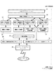
図1は本発明に係る一実施例の画像入力装置のシステム・ブロック図である。1はシステム・バスであり、これから説明する各構成ブロックはこのシステム・バスに接続されている。2はCPU(Centrtal ProcessingUnit)である。3はプログラム・メモリ(PMEMと称す)で、本処理のためのプログラムを適宜ハード・ディスク15から選択/読込みし、2のCPUにて実行する。又、キーボード12から入力されたデータはテキスト・メモリでもあるPMEMにコード情報として格納される。4は通制御部であり、5の通信ポートに於ける入出力データの制御を行う。通信ポート5から出力された信号は、通信回線6を経由してネットワーク上の他の装置7の通信ポートに伝えられる。ネットワーク上で共有されているプリンタ等の画像出力装置やスキャナ等の画像入力装置とのやり取りはこの通信制御部4を介して行われる。
【0014】
また、本実施例ではこの通信回線6としてLANなどのネットワークに関して記述するが、この通信制御部に接続される通信ポート及び通信回線が一般の公衆回線であっても本発明が適応されることは言うまでもない。
【0015】
8は外部記憶装置制御部、9、10はデータファイル用のディスクで、例えば9はフロッピー・ディスク(FDと称す)であり、10はハード・ディスク(HDと称す)である。
【0016】
11は入力制御部であり、12のキーボード、13のマウス等の入力装置が接続される。操作者はこのキーボード11を操作することによりシステムの動作指令等を行う。また、13はCRT16上で画像情報を加工指示するためのポインティング・デバイス(PDと称す)であり、本実施例ではマウスを使用している。これによりCRT16上のカーソルをX,Y方向任意に移動してコマンドメニュー上のコマンド・アイコンを選択して処理の指示を行なうほか編集対象の指示、描画位置の指示等も行なう。
【0017】
14はビデオ・イメージ・メモリ(VRAMと称す)、15は表示出力制御部、16はCRTである。16のCRTに表示されるデータは11のVRAM上にビットマップデータとして展開されている。
【0018】
17はプリンタ制御部であり、接続されているプリンタ18に対するデータの出力制御を行う。
【0019】
1Aは画像入力機器制御部であり、接続されている画像入力機器1Bの制御を行う。本実施例における画像入力サーバ装置には、1A、1Bの構成要素が必須であるが、クライアント側装置では前述のように通信制御部4、及び通信ポート5を介してサーバ側の共有されている同構成要素を使用することができるので必ずしも必須ではない。
【0020】
更に、図1の構成は、画像入力機器と画像入力機器制御部が物理的に別々のコンポーネントであっても、画像入力機器が、画像入力機器制御部を含む1つのコンポーネントであっても同様な機能を有することとする。
【0021】
図2に本実施例の画像入力サーバ装置における各機能の構成例を示す。
【0022】
同図に於いて21は、ネットワークサーバモジュールである。本モジュールでは、以下に述べるサーバ拡張機能から得られたデータを、汎用のネットワークプロトコルに対応したネットワーク上でやり取り可能なデータ形式に変換する。
【0023】
また、その逆にクライアント側から送られてきたネットワークデータを、サーバ拡張モジュールが解釈可能な内部データ形式に変換する。
【0024】
サーバ拡張モジュール22は、サーバから渡されたデータを解析して本モジュールの管理下にある複数のイメージサービスモジュール中から指示されたものを選択してそのサービスを提供する。又は、あるサービスモジュールから別のサービスモジュールへのデータの受け渡しを行う(例えばOCRモジュールから、画像入出力制御モジュールを呼び出す等)。
【0025】
共通インターフェース変換モジュール23は、サーバ拡張モジュールからいずれかの画像入力機器のサービスの提供が要求された場合に、その時の要求データを指示された入力機器制御モジュール26に対応した制御命令に変換するためのものである。またその逆に、入力機器制御モジュールから上がってきた機器固有の制御情報を、サーバ拡張モジュールに渡せるような一般的なインターフェースに変換する機能も持つ。具体的には、一方は、クライアントからのイメージ読み込みパラメータ設定情報であり、もう一方は、読み取り指示の結果得られた画像情報及びその付属情報である。
【0026】
OCR用モジュール24は、クライアントから、画像入力機器で読み取られたイメージデータを文書データとして変換する要求があった時に、サーバ拡張モジュール22からcallされる。イメージデータ形式変換モジュール25は、画像入力機器から得られたイメージデータの形式を、クライアントで指定されたイメージデータ形式に変換するためのモジュールである。
【0027】
入出力機器制御モジュール26は個々の画像入力機器27応じてその制御を行うものであり、個々の機器に応じた(特化した)制御命令/情報の入出力を司る。
【0028】
図3に本実施例の画像入力クライアント装置における各機能の構成例を示す。
【0029】
同図に於いては、画像入力機器接続情報生成モジュール36が必要となる。
【0030】
同図の31〜34の構成は、一般アプリケーションからクライアント装置にローカルに接続されている画像入力機器をアクセスするために必要なものである。本実施例におけるクライアント拡張機能は同図の35〜3Aの構成からなる。
【0031】
31は画像入力機能を有する一般のアプリケーション。32はそのアプリケーションに対して汎用の画像入出力インターフェースを提供する、画像入出力機器マネージャである。同マネージャは、上記入出力インターフェースによる指示に応じて、その管理下にある画像入出力機器制御モジュールの中から指示されたものに対して情報のやりとりを行う。
【0032】
33は、汎用i/oを持つ画像入力機器制御モジュールである。本モジュールは、画像入力マネージャ32との間で取り決めされた、汎用的なインターフェースによって個々に接続された画像入力機器を制御するためのものである。本モジュールは、前述、画像入力機器制御モジュール26とは異なり、汎用のインターフェースを提供している。即ち、機能的には、画像入力機器制御モジュール26と、共通インターフェース変換モジュール23と、汎用画像入出力インターフェース変換モジュール37とを合わせたものとなっている。即ち、32は、例えば、TWAINマネージャであり、33は、個々の機器に対応したTWAINドライバに相当する。
【0033】
34は本装置にローカルに接続されている個々の画像入力機器である。
【0034】
以降に本発明に於けるクライアント拡張機能を構成する要素項目について述べる。
【0035】
クライアント機能制御モジュール35は、以下に述べる個々のクライアント拡張機能を構成するモジュールの全体管理を行うものである。画像入力機器接続情報生成モジュール36は、ネットワーククライアントモジュール38を利用して得られたサーバ装置側に接続されている画像入出力装置の属性情報、及びネットワーク接続に必要な情報を獲得して、個々の画像入力機器接続情報3Aを生成するためのモジュールである。この時、同時に仮想画像入力機器制御モジュール39も自動的に生成される。このモジュールが生成されることによって、画像入力機器マネージャ32は、ネットワーク上の機器が、仮想的に接続されているように扱う事が可能となる。
【0036】
汎用画像入出力インターフェース変換モジュール37は、ネットワーククライアントモジュール38を利用して得られた、サーバ側の画像入力機器に対する制御情報を、画像入力マネージャ32に対応した汎用的なインターフェースに変換するためのものである。本モジュールは、直接これらインターフェースを持つ機能を直接画像入力マネージャ32に提供するのではなく、後述のように個々の仮想画像入力機器制御モジュールを経由して提供する。
【0037】
ネットワーククライアントモジュール38は、これらモジュールとサーバ側のモジュールが通信を行うことのできるように汎用のネットワークプロトコルに対応したネットワーク上でやり取り可能なデータ形式に変換する。
【0038】
仮想画像入力機器制御モジュール39は、設定されているネットワーク上の画像入力機器と1対1に生成される。本モジュールは、基本的には対応する画像入力機器接続情報3Aの情報を返す、或いは、同情報を汎用画像入出力インタフェース提供モジュール37に渡して、その結果を画像入力マネージャ32に渡すといった中間的に介在する処理のみを行う。
【0039】
このように、実際の処理の大部分を汎用画像入出力インターフェース変換モジュール37が行ってくれるので当該モジュールは小さくて済み、複数のネットワーク上の画像入力機器用のモジュールが作成されてもオーバヘッドは少なくて済む。
【0040】
図4に、図3で示されている画像入力機器接続情報のデータ構造例について示す。同図に於いて、401〜404までは、当該画像入力機器へのネットワーク接続情報である。
【0041】
まず、401は、ネットワーク上に於いて接続先のサーバを識別するための情報、即ち、ネットワーク上でのマシン名称、もしくはネットワークアドレスが設定されている。
【0042】
402は、当該ネットワーク上で共有設定されている画像入力装置を識別するための同機器のネットワーク名称が設定されている。403には、同機器を使用する際にセキュリティ制限が設定されている場合に、使用許可を求めるためのセキュリティ許可情報を格納する。このような情報は、例えば、使用許可を求めるパスワード等である。
【0043】
404は、上記以外のネットワーク接続に必要な情報を示す。
【0044】
405〜408は、前述の画像入力機器マネージャに対して仮想的な機器情報を提供するための、機器の識別情報である。これら情報は、サーバ装置側から読み込まれたものがこの領域に保存される。
【0045】
まず、405は、機器の名称情報である。406はモジュールのバージョン情報である。407は、当該モジュールの作成者の情報である。408は、その他の識別情報である。409〜414は、当該画像入力機器の機能情報を示す。その中でも、本実施例ではn個の機能情報が存在する場合を示しており、409〜411及び412〜414がそれぞれひとまとまりの機能情報である事を示している。ここでいう機能情報とは、例えば、読み込み領域の対応サイズ情報や、読み込み可能解像度のリスト等、当該機器の有する能力を示すものである。
【0046】
409は、当該機能の内容を示す識別子。410は、その機能を表すデータの形式を表す識別子である。これは、例えば、機能情報の形式が一つの値である、ある範囲の値である、列挙形式(1, 5, 10,15)等である、といった識別をするための情報である。
【0047】
411には、前述データ形式に従って実際の機能情報が設定されている。412〜414には409〜411と同様な形式でn番目の機能情報が設定されている。
【0048】
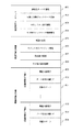
図5に、画像入力機器マネージャから、仮想画像入力機器制御モジュールに対して、ネットワーク上の画像入力機器へのアクセス要求があった場合に、どのように処理されるという、クライアント側の内部処理のフローチャートを示す。ここで、本フローチャートの手順はPMEM3に格納されたプログラムをCPU2により実行する事により実現される。
【0049】
まず、ステップS51で、汎用のインタフェースを使用して画像入力マネージャから仮想画像入力機器制御モジュールに対して要求がくる。
【0050】
次にステップS52で、当該要求が、仮想画像入力機器制御モジュールで処理可能か否かを判定する。これは、例えば、機器の識別情報等は本モジュール内で処理可能であり、実際の画像データの獲得等は、処理不可能である。
【0051】
ステップS52で処理可能であると判定されるとステップS53に分岐し、そうでは無いと判定された場合にはステップS54に分岐する。ステップS53では、画像入力機器接続情報を使用して本モジュール内で要求されているデータを生成する。
【0052】
ステップS54では、画像入力機器接続情報から必要な情報を読み出して汎用画像入出力インタフェース変換モジュールをコールする。ステップS55で、当該要求が汎用画像入出力インタフェース変換モジュールで処理可能か否かを判定する。これは、例えば、機器に対しての一部属性の設定等は本モジュール内の設定のみで済ませ、実際にネットワークに対してアクセスしなければならなくなった時にこれまで設定された情報をまとめて、サーバ側に送信すれば効率が良くなる。同ステップで、本モジュールに於いて処理可能であると判定された場合にはステップS56に分岐し、そうでは無いと判定された場合にはステップS57に分岐する。
【0053】
ステップS56では、汎用画像入出力インターフェース変換モジュールで、上から要求されたデータを処理する。ステップS57では、画像入力機器接続情報から当該画像入力装置が接続されているネットワーク上のサーバ装置に対して、要求を出す。
【0054】
ステップS58では、前のステップで、サーバに出した要求に対して応答が返ってきた時に、汎用画像入出力インターフェース変換モジュールによって画像入出力機器マネージャが解釈できる(汎用的な)データ形式に変換する。
【0055】
以上、いずれかの処理によって画像入力機器マネージャは、所望のリターン情報を得ることができる。
【0056】
図6に、クライアント装置から、サーバ装置に接続されている画像入力機器に対して要求があった場合にどのように処理されるという、サーバ側の内部処理のフローチャートを示す。
【0057】
まず、ステップS601で、ネットワーク経由でクライアント側からの要求を受け取る。次にステップS602で、前述クライアントからの要求が、初めてのセッションか否かを判定する。
【0058】
既に、セッションが開始されているクライアントからの要求であれば、S601得られるデータにはセッションid(識別情報)が付加されている。本ステップで初めてのセッションであると判定された場合には、ステップS603に分岐し、そうでは無いと判定された場合にはステップS605に分岐する。
【0059】
ステップS603では、要求のあったクライアントに対して本サーバ装置がアクセスを許可しているか否かを判定し、許可している場合にはステップS604に分岐し、そうではない場合にはアクセス拒否の通知をクライアントに返す。
【0060】
ステップS604では、要求のあったクライアントとサーバの間でセッションのオープンを行い、その結果としてのセッションidを返す。このセッションidは、クライアント側からクローズの要求がくるか、サーバ装置に於けるサーバプロセスが終了するまで有効である。当然のことながら、サーバは同時に複数のクライアントとの間で同時にセッションを確立することができる。
【0061】
S605では、既にセッションがオープンされているクライアントからの要求があった場合で、本ステップでサーバに対して指示されたセッションidが有効か否かをチェックする。本ステップで、有効なセッションidであると判定された場合には、ステップS606に分岐し、そうでは無いと判定された場合には無効なセッションであるとの通知をクライアント側に返す。
【0062】
ステップS606では、クライアントからの要求がセッションの終了処理であるか否かを判定し、そうであると判定された場合にはステップS607に分岐し、そうでは無いと判定された場合には、ステップS608に分岐する。
【0063】
ステップS607では、指示されたクライアントとの間のセッションのクローズ処理を行い、終了処理に移る。
【0064】
ステップS608では、クライアントから指示された画像入力機器は有効であるか否かをチェックして、有効であると判定された場合にはステップS609に分岐し、そうでは無いと判定された場合には無効なプリンタであるとの通知をクライアント側に返して、終了処理を行う。
【0065】
ステップS609では、当該画像入力機器に対応する画像入力機器制御モジュールに対してクライアントからの要求情報を渡す。ステップS610では、当該画像入力機器制御モジュールからのリターン情報を得る。ステップS611では、前ステップで得られた結果をネットワークを経由してクライアント側に伝える。
【0066】
図7に本実施例の機能を実現するための、仮想的な画像読み取り機器接続設定画面の一例を示す。
【0067】
同図で設定された情報は、図3の画像入力機器接続情報生成モジュール36の動作に反映されてユーザの所望する画像入力機器に対してのみ仮想的な接続情報が作成される。
【0068】
同図に於いて、71はネットワーク上で共有設定されている画像入力機器を探索する際のネットワーク範囲を指定するものである。これは例えば、windowsの環境下で言えば或るドメインに相当する。72は当該ネットワークの範囲内に発見された画像入力機器の一覧である。本例においては、画像入力機器の共有名称と括弧中に当該機器が接続されているサーバ装置のネットワーク名称が示されている。73はクライアント装置に於いて、仮想的な接続情報を作成する画像入力機器の一覧である。本リストに表示されたものはクライアント装置に直接接続されている画像入力装置であるかのように機器リストに表示され、同時に実際の画像読み込みの指定を行うことが可能である。74は仮想接続設定に追加を指示するためのボタンコントール。75が同リストから削除を指示するためのボタンコントールである。削除が指示されると当該機器の仮想的な接続情報が失われるので、同機器をクライアント装置から使用することが不可能となる。76は指示されたネットワーク内に於ける画像入力機器探索を指示するボタンコントロールである。78は本ダイアログでの設定を反映させて終了することを指示するボタンコントロール。79は同様に設定をキャンセルして終了することを指示するボタンコントロールである。
【0069】
【発明の効果】
以上説明したように、画像入力機器をネットワーク上で共有可能とし、かつ、その制御をクライアント側から汎用画像入出力インターフェースを用いて行うことを可能とすることによって、所望の画像入力装置がネットワーク上に存在するか、或いは直接ローカルに接続されているか、という事を意識する必要がなくなった。
【0070】
その結果、クライアント装置側のユーザは現在行っている作業を中断することなく、ネットワーク上で共有されている画像入力装置を使用することが可能となった。
【0071】
また、ネットワーク上に存在する画像入力装置の情報をもとにして、汎用的な画像入出力インターフェースに対応した仮想的な画像入力機器接続情報をクライアント装置に自動的に生成することにより、クライアント側でユーザが個別の接続情報をインストールすることなく仮想的な機器の追加を可能とする事が可能となった。
【0072】
更に、ネットワーク内に存在する複数の画像入力サーバ装置の中から所望のものを選択し、選択されたものに対してのみ仮想的な画像入力機器接続情報を生成する機能を提供することによって、クライアント装置側に無駄な入力情報を生成せず処理効率を向上させ、或いはその情報の占有領域を節約することが可能となった。
【図面の簡単な説明】
【図1】本発明に係る一実施例の画像入力装置のシステム・ブロック図。
【図2】本実施例の画像入力サーバ装置における各機能の構成例を示す図。
【図3】本実施例のクライアント側装置における画像入力装置の設定画面を示す図。
【図4】画像入力機器接続情報のデータ構造例を示す図。
【図5】仮想画像入力機器制御モジュールに対して、ネットワーク上の画像入力機器へのアクセス要求があった場合の処理例を表すフローチャート。
【図6】クライアント装置から、サーバ装置に接続されている画像入力機器に対して要求があった場合の処理例を表すフローチャート。
【図7】仮想的な画像読み取り機器接続設定画面の一例を示す図。
【符号の説明】
1 システム・バス
2 CPU
3 プログラム・メモリ
4 通制御部
5 通信ポート
6 通信回線
7 ネットワーク上の他の装置
8 外部記憶装置制御部
9、10 データファイル用のディスク
11 入力制御部
12 キーボード
13 マウス等の入力装置
14 ビデオ・イメージ・メモリ
15 表示出力制御部
16 CRT
17 プリンタ制御部
18 プリンタ
19 外部機器制御部
1A 画像入力装置制御部
1B 画像入力機器[0001]
BACKGROUND OF THE INVENTION
The present invention relates to a network system and a client device thereof, and particularly enables an image reading apparatus to be operated regardless of the type of interface.
[0002]
[Prior art]
In the conventional image input device, the image input devices cannot be shared on the network and controlled using a general-purpose image input / output interface.
[0003]
[Problems to be solved by the invention]
As described above, in the prior art, since the image input device could not be freely controlled on the network, a user who wants to use the image input device on the client device side himself / herself connected to the image input device. I had to go to the device where it was, and instructed to input directly with the device, and stored the obtained image data in the desired location.
[0004]
Alternatively, a dedicated client application that does not support a general-purpose image input / output interface is started, an image is acquired via the network, and then a desired image editing application is opened to edit the previous image data.
[0005]
As described above, in any case, when an image is to be captured on the network, the current operation must be temporarily interrupted.
[0006]
The present invention has been made in view of such a conventional technique, and makes it possible to use an image input device shared on a network without interrupting a current operation to a user on the client device side. The first purpose.
[0007]
A second object of the present invention is to allow a user to add a virtual device on the client side without installing individual connection information.
[0008]
Furthermore, a third object of the present invention is to improve processing efficiency without generating unnecessary input information on the client device side, or to save an occupied area of the information.
[0009]
[Means for Solving the Problems]
For the present invention to achieve the above object, the images input device, and converts an input equipment control means for controlling the operation of the image input device, the information of the input device control unit for general-purpose network protocol network and a Rene Tsu network server means to provide the above, the client device capable of communicating with an image input server device on a network, and a client device corresponding to the general network protocol, using said client means device control information of the image input device provided in the image input server device was collected using a and a interns face converting means for converting the data format that can be interpreted general image input and output interface, the image input server device image input network client device capable of controlling the operation of a device included in, Bei the city Network system, characterized in that it is configured Te that provides.
[0012]
DETAILED DESCRIPTION OF THE INVENTION
Hereinafter, the present invention will be described in more detail with reference to the drawings.
[0013]
FIG. 1 is a system block diagram of an image input apparatus according to an embodiment of the present invention. Reference numeral 1 denotes a system bus, and each component block described below is connected to the system bus. Reference numeral 2 denotes a CPU (Central Processing Unit). Reference numeral 3 denotes a program memory (referred to as PMEM). A program for this processing is appropriately selected / read from the
[0014]
In this embodiment, a network such as a LAN is described as the
[0015]
8 is an external storage device control unit, 9 and 10 are data file disks, for example, 9 is a floppy disk (referred to as FD), and 10 is a hard disk (referred to as HD).
[0016]
[0017]
14 is a video image memory (referred to as VRAM), 15 is a display output control unit, and 16 is a CRT. Data displayed on the 16 CRTs are expanded as bitmap data on the 11 VRAMs.
[0018]
[0019]
Reference numeral 1A denotes an image input device control unit that controls the connected image input device 1B. In the image input server device according to the present embodiment, the components 1A and 1B are indispensable. On the client side device, the server side is shared via the communication control unit 4 and the
[0020]
Further, the configuration of FIG. 1 is the same even if the image input device and the image input device control unit are physically separate components, or the image input device is a single component including the image input device control unit. It has a function.
[0021]
FIG. 2 shows a configuration example of each function in the image input server device of the present embodiment.
[0022]
In the figure,
[0023]
Conversely, the network data sent from the client side is converted into an internal data format that can be interpreted by the server extension module.
[0024]
The
[0025]
The common
[0026]
The
[0027]
Output
[0028]
FIG. 3 shows a configuration example of each function in the image input client device of the present embodiment.
[0029]
In the figure, an image input device connection
[0030]
The
[0031]
31 is a general application having an image input function. An image input /
[0032]
[0033]
[0034]
The element items constituting the client extension function in the present invention will be described below.
[0035]
The client
[0036]
The general-purpose image input / output
[0037]
The network client module 38 converts the data into a data format that can be exchanged on a network corresponding to a general-purpose network protocol so that these modules and the module on the server side can communicate with each other.
[0038]
The virtual image input
[0039]
In this way, since the general-purpose image input / output
[0040]
FIG. 4 shows an example of the data structure of the image input device connection information shown in FIG. In the figure,
[0041]
First,
[0042]
[0043]
[0044]
[0045]
First,
[0046]
[0047]
In 411, actual function information is set according to the data format. The nth function information is set in 412 to 414 in the same format as 409 to 411.
[0048]
FIG. 5 shows the internal processing on the client side in which the processing is performed when the image input device manager requests the virtual image input device control module to access the image input device on the network. A flowchart is shown. Here, the procedure of this flowchart is realized by the CPU 2 executing a program stored in the PMEM 3.
[0049]
First, in step S51, a request is sent from the image input manager to the virtual image input device control module using a general-purpose interface.
[0050]
In step S52, it is determined whether the request can be processed by the virtual image input device control module. For example, device identification information can be processed in this module, and actual image data acquisition cannot be processed.
[0051]
If it is determined in step S52 that processing is possible, the process branches to step S53. If it is determined that this is not the case, the process branches to step S54. In step S53, data requested in this module is generated using the image input device connection information.
[0052]
In step S54, necessary information is read from the image input device connection information and the general-purpose image input / output interface conversion module is called. In step S55, it is determined whether or not the request can be processed by the general-purpose image input / output interface conversion module. This means that, for example, setting of some attributes for the device only needs to be set in this module, and when the user actually has to access the network, the information set up to now is collected, If it is sent to the server side, the efficiency is improved. If it is determined in this step that processing can be performed in this module, the process branches to step S56, and if not, the process branches to step S57.
[0053]
In step S56, the general image input / output interface conversion module processes the data requested from above. In step S57, a request is issued from the image input device connection information to the server device on the network to which the image input device is connected.
[0054]
In step S58, when a response is returned to the request issued to the server in the previous step, the general-purpose image input / output interface conversion module converts the data into a (general-purpose) data format that can be interpreted by the image input / output device manager. .
[0055]
As described above, the image input device manager can obtain desired return information by any of the processes.
[0056]
FIG. 6 shows a flowchart of internal processing on the server side in which processing is performed when a request is made from the client device to the image input device connected to the server device.
[0057]
First, in step S601, a request from the client side is received via the network. In step S602, it is determined whether the request from the client is the first session.
[0058]
If it is a request from a client that has already started a session, a session id (identification information) is added to the data obtained in S601. If it is determined that the session is the first session in this step, the process branches to step S603. If it is determined that this is not the case, the process branches to step S605.
[0059]
In step S603, it is determined whether or not the server apparatus permits access to the requested client. If permitted, the process branches to step S604, and if not, access is denied. Return notification to client.
[0060]
In step S604, a session is opened between the requested client and server, and the resulting session id is returned. This session id is valid until a close request is received from the client side or the server process in the server device is terminated. Of course, the server can establish a session with multiple clients simultaneously.
[0061]
In S605, when there is a request from a client whose session is already open, it is checked whether or not the session id instructed to the server in this step is valid. If it is determined in this step that the session id is valid, the process branches to step S606, and if it is not so, a notification that the session is invalid is returned to the client side.
[0062]
In step S606, it is determined whether or not the request from the client is a session termination process. If it is determined to be, the process branches to step S607; Branch to S608.
[0063]
In step S607, a process for closing a session with the instructed client is performed, and the process proceeds to an end process.
[0064]
In step S608, it is checked whether the image input device instructed by the client is valid. If it is determined that the image input device is valid, the process branches to step S609; A notification that the printer is invalid is returned to the client side, and the termination process is performed.
[0065]
In step S609, request information from the client is passed to the image input device control module corresponding to the image input device. In step S610, return information from the image input device control module is obtained. In step S611, the result obtained in the previous step is transmitted to the client side via the network.
[0066]
FIG. 7 shows an example of a virtual image reading device connection setting screen for realizing the functions of the present embodiment.
[0067]
The information set in this figure is reflected in the operation of the image input device connection
[0068]
In the figure,
[0069]
【The invention's effect】
As described above, the image input device can be shared on the network, and the control can be performed from the client side using the general-purpose image input / output interface. It is no longer necessary to be aware of whether it exists in the network or is connected directly to the local.
[0070]
As a result, the user on the client device side can use the image input device shared on the network without interrupting the current work.
[0071]
Further, by automatically generating virtual image input device connection information corresponding to a general-purpose image input / output interface on the client device based on the information of the image input device existing on the network, the client side This makes it possible for a user to add a virtual device without installing individual connection information.
[0072]
Further, by selecting a desired one from a plurality of image input server devices existing in the network and providing a function of generating virtual image input device connection information only for the selected one, the client It is possible to improve the processing efficiency without generating useless input information on the apparatus side, or to save the occupied area of the information.
[Brief description of the drawings]
FIG. 1 is a system block diagram of an image input apparatus according to an embodiment of the present invention.
FIG. 2 is a diagram illustrating a configuration example of each function in the image input server device according to the embodiment.
FIG. 3 is a diagram showing a setting screen of the image input device in the client side device according to the embodiment.
FIG. 4 is a diagram showing an example of the data structure of image input device connection information.
FIG. 5 is a flowchart illustrating a processing example when an access request to an image input device on a network is made to the virtual image input device control module.
FIG. 6 is a flowchart illustrating a processing example when a request is made from the client device to the image input device connected to the server device.
FIG. 7 is a diagram showing an example of a virtual image reading device connection setting screen.
[Explanation of symbols]
1 System bus 2 CPU
3 Program memory 4
17
Claims (2)
上記汎用的なネットワークプロトコルに対応したクライアント手段と、上記クライアント手段を使用して得られた上記画像入力サーバ装置が備える画像入力機器の機器制御情報を、汎用的な画像入出力インターフェースが解釈できるデータ形式に変換するインターフェース変換手段とを有し、上記画像入力サーバ装置が備える画像入力機器の動作を制御することが可能なネットワーククライアント装置、とを備えて構成されることを特徴とするネットワークシステム。 And images input device, an input device control means for controlling the operation of the image input device, and Rene Tsu network server means provides to the network to convert the information of the input device control section to the general-purpose network protocol the provided, the client device capable of communicating with an image input server device on the network, and,
Data that can be interpreted by a general-purpose image input / output interface for device control information of a client unit corresponding to the general-purpose network protocol and an image input device provided in the image input server device obtained by using the client unit and a interns face converting means for converting the format, the network characterized in that it is configured the image input server device image input network client device capable of controlling the operation of equipment provided is provided with a capital system.
Priority Applications (5)
| Application Number | Priority Date | Filing Date | Title |
|---|---|---|---|
| JP28411198A JP3997008B2 (en) | 1998-10-06 | 1998-10-06 | Network system |
| US09/410,095 US6751648B2 (en) | 1998-10-06 | 1999-10-01 | System for sharing image input device on network |
| EP99307797A EP0993178A3 (en) | 1998-10-06 | 1999-10-04 | System for sharing image input device on network |
| DE69943224T DE69943224D1 (en) | 1998-10-06 | 1999-10-04 | System and method for participation in an image input device on a network |
| EP03079051A EP1411438B1 (en) | 1998-10-06 | 1999-10-04 | System and method for sharing image input device on network |
Applications Claiming Priority (1)
| Application Number | Priority Date | Filing Date | Title |
|---|---|---|---|
| JP28411198A JP3997008B2 (en) | 1998-10-06 | 1998-10-06 | Network system |
Publications (3)
| Publication Number | Publication Date |
|---|---|
| JP2000115438A JP2000115438A (en) | 2000-04-21 |
| JP2000115438A5 JP2000115438A5 (en) | 2005-11-24 |
| JP3997008B2 true JP3997008B2 (en) | 2007-10-24 |
Family
ID=17674344
Family Applications (1)
| Application Number | Title | Priority Date | Filing Date |
|---|---|---|---|
| JP28411198A Expired - Fee Related JP3997008B2 (en) | 1998-10-06 | 1998-10-06 | Network system |
Country Status (1)
| Country | Link |
|---|---|
| JP (1) | JP3997008B2 (en) |
Families Citing this family (1)
| Publication number | Priority date | Publication date | Assignee | Title |
|---|---|---|---|---|
| JP4873699B2 (en) * | 2006-06-12 | 2012-02-08 | 株式会社リコー | Image processing system, image processing apparatus, and program |
-
1998
- 1998-10-06 JP JP28411198A patent/JP3997008B2/en not_active Expired - Fee Related
Also Published As
| Publication number | Publication date |
|---|---|
| JP2000115438A (en) | 2000-04-21 |
Similar Documents
| Publication | Publication Date | Title |
|---|---|---|
| US7539785B2 (en) | Network device manager | |
| US6782426B1 (en) | Shared device control method and server-client system | |
| US20070297006A1 (en) | Output management device setting apparatus and setting method | |
| US6751648B2 (en) | System for sharing image input device on network | |
| US6754695B2 (en) | Server device that manages a state of a shared device, and method of controlling same | |
| JP3997008B2 (en) | Network system | |
| JPH09146725A (en) | Printing system | |
| US20030184573A1 (en) | Network terminal apparatus and method of presenting display thereon | |
| JP4560154B2 (en) | Data processing apparatus, data processing method, and computer-readable recording medium | |
| JP2000293622A (en) | Method and device for image processing and storage medium | |
| JP2002189546A (en) | Network terminal equipment, display control method and display control program | |
| JP3706762B2 (en) | Display processing method, data processing apparatus, and computer-readable storage medium | |
| JP2000293464A (en) | Data processor and display processing method and storage medium for storing computer readable porogram | |
| JP2004110375A (en) | Device list display method | |
| JP2000115439A (en) | Network system and client device thereof | |
| JP2000112595A (en) | Network system | |
| JP2001109692A (en) | Device, method and system for processing data and computer readable recording medium | |
| JP2003058442A (en) | Information processor, network system, device management method, storage medium and program | |
| JP2000293473A (en) | Network terminal device and its display method | |
| JP2003150467A (en) | Information processor, network system, displaying method device managing method, storage medium and program | |
| JP2000293332A (en) | Processor and method for information processing | |
| JP2000115424A (en) | Network system and server device thereof | |
| JP2000112872A (en) | Network client device | |
| JP2000115448A (en) | Terminal, image read system, and image read method and storage medium thereof | |
| JP2000295482A (en) | Image input device, image input system, image input method and medium with image processing program recorded therein |
Legal Events
| Date | Code | Title | Description |
|---|---|---|---|
| A521 | Written amendment |
Free format text: JAPANESE INTERMEDIATE CODE: A523 Effective date: 20051006 |
|
| A621 | Written request for application examination |
Free format text: JAPANESE INTERMEDIATE CODE: A621 Effective date: 20051006 |
|
| A131 | Notification of reasons for refusal |
Free format text: JAPANESE INTERMEDIATE CODE: A131 Effective date: 20070508 |
|
| A521 | Written amendment |
Free format text: JAPANESE INTERMEDIATE CODE: A523 Effective date: 20070703 |
|
| TRDD | Decision of grant or rejection written | ||
| A01 | Written decision to grant a patent or to grant a registration (utility model) |
Free format text: JAPANESE INTERMEDIATE CODE: A01 Effective date: 20070724 |
|
| A61 | First payment of annual fees (during grant procedure) |
Free format text: JAPANESE INTERMEDIATE CODE: A61 Effective date: 20070806 |
|
| FPAY | Renewal fee payment (event date is renewal date of database) |
Free format text: PAYMENT UNTIL: 20100810 Year of fee payment: 3 |
|
| R150 | Certificate of patent or registration of utility model |
Free format text: JAPANESE INTERMEDIATE CODE: R150 |
|
| FPAY | Renewal fee payment (event date is renewal date of database) |
Free format text: PAYMENT UNTIL: 20100810 Year of fee payment: 3 |
|
| FPAY | Renewal fee payment (event date is renewal date of database) |
Free format text: PAYMENT UNTIL: 20110810 Year of fee payment: 4 |
|
| FPAY | Renewal fee payment (event date is renewal date of database) |
Free format text: PAYMENT UNTIL: 20120810 Year of fee payment: 5 |
|
| LAPS | Cancellation because of no payment of annual fees |