JP3996396B2 - System and method for production of 18F fluoride - Google Patents
System and method for production of 18F fluoride Download PDFInfo
- Publication number
- JP3996396B2 JP3996396B2 JP2001562717A JP2001562717A JP3996396B2 JP 3996396 B2 JP3996396 B2 JP 3996396B2 JP 2001562717 A JP2001562717 A JP 2001562717A JP 2001562717 A JP2001562717 A JP 2001562717A JP 3996396 B2 JP3996396 B2 JP 3996396B2
- Authority
- JP
- Japan
- Prior art keywords
- fluoride
- solvent
- reaction chamber
- separator
- gas
- Prior art date
- Legal status (The legal status is an assumption and is not a legal conclusion. Google has not performed a legal analysis and makes no representation as to the accuracy of the status listed.)
- Expired - Fee Related
Links
Images

Classifications
-
- G—PHYSICS
- G21—NUCLEAR PHYSICS; NUCLEAR ENGINEERING
- G21G—CONVERSION OF CHEMICAL ELEMENTS; RADIOACTIVE SOURCES
- G21G1/00—Arrangements for converting chemical elements by electromagnetic radiation, corpuscular radiation or particle bombardment, e.g. producing radioactive isotopes
- G21G1/04—Arrangements for converting chemical elements by electromagnetic radiation, corpuscular radiation or particle bombardment, e.g. producing radioactive isotopes outside nuclear reactors or particle accelerators
- G21G1/10—Arrangements for converting chemical elements by electromagnetic radiation, corpuscular radiation or particle bombardment, e.g. producing radioactive isotopes outside nuclear reactors or particle accelerators by bombardment with electrically charged particles
-
- G—PHYSICS
- G21—NUCLEAR PHYSICS; NUCLEAR ENGINEERING
- G21G—CONVERSION OF CHEMICAL ELEMENTS; RADIOACTIVE SOURCES
- G21G1/00—Arrangements for converting chemical elements by electromagnetic radiation, corpuscular radiation or particle bombardment, e.g. producing radioactive isotopes
- G21G1/001—Recovery of specific isotopes from irradiated targets
- G21G2001/0015—Fluorine
Abstract
Description
【0001】
(関連出願の記載)
この出願は、2000年2月23日に出願された米国仮出願の米国特許法第119条(e)による優先権を主張し、その仮出願の全内容は、ここでの引用により、本出願に組み込まれる。
【0002】
(技術分野)
本出願は、18Oから18Fフッ化物を生産する技術に関する。
【0003】
(背景技術)
生物組織の性質と、それらの組織を含む機関の機能を診断する多くの医学的処置は、組織の中に導入され、または、組織によって摂取される放射源を必要とする。好ましくは、そのような放射源は、数時間の寿命を持っていて、これは、組織を傷つけるほど長くなく、また診断を完了するまでに放射強度が減衰するほど短くもない。好ましくは、そのような放射源は、化学的に毒性でない。18Fフッ化物は、そのような放射源である。
【0004】
18Fフッ化物は、約109.8分の寿命を持ち、トレーサー量では化学的に毒性ではない。したがって、18Fフッ化物は、医学用生成物と放射性医薬品の製造において多くの用途を持っている。18Fフッ化物アイソトープは、求核性フッ素処理を介して化合物をラベル付けるのに使用できる。1つの重要な用途は、陽電子放射断層写真法の撮像での使用のための放射トレーサー化合物の生成である。フッ化デオキシグルコース(FDG)は、18Fフッ化物を含む放射トレーサー化合物の1例である。FDGに加えて、18Fフッ化物でのラベル付けに適した放射トレーサー化合物は、フッ化デオキシグルコース(FDG)、フッ化チミジン(FLT)、脂肪酸のフッ化類似化合物、ホルモンのフッ化類似化合物、ペプチド、DNA、オリゴヌクレオチド、蛋白質及びアミノ酸をラベル付ける架橋薬品を含むが、これらに限定されない。
【0005】
核ビーム(陽子、重陽子、アルファ粒子などを含む)の放射により誘導されるいくつかの核反応は、アイソトープ18Fフッ化物を作る。核反応を行う18Fフッ化物は、20Ne(d,α)18F(これは、重陽子を吸収して18Fを生じ、かつ、α粒子を放出する20Neを表わす表記である)、16O(α,pn)18F、16O(3H,n)18F、16O(3H,p)18F、18O(p,n)18Fを含むが、これに限定されない。ここで、18Fの最大の収率は、最大の断面積を持っているため、18O(p,n)18Fにより得られる。(ネオン、水及び酸素を含む)いくつかの元素と化合物は、核反応を介して18Fを得るときの反応当初の材料として使用される。
【0006】
技術的及び経済的考慮は、18F生産システムを選択するときの重要な因子である。18Fの半減期は約109.8分であるので、18Fの生産者は、大量の18Fを急速に作るため、断面積の大きい(すなわち、アイソトープ生産効率が高い)核反応を好む。さらに、18Fの半減期は約109.8分であるので、作られた18Fアイソトープの一部が輸送中に失われるのを避けるため、18Fの使用者は、使用者の設備の近くに18F生産工場があることを好む。加速器の設計が進歩したので、より大きなエネルギーと流れの陽子ビーム源が利用できるようになった。
【0007】
陽子ビームを作るシステムは、他の種類のビームを作るシステムに比べて、操作と維持において、複雑さがより少なく、より簡単である。したがって、技術的および経済的な考慮のため、使用者は、陽子ビームを使用する18F生産システムや陽子ビームで利用できるのと同じパワー出力を使用する18F生産システムの方を好むようになる。また、経済的考慮のため、使用者は、高価な操業開始化合物を効率的に使用し保存するようになる。
【0008】
しかし、18F化合物の固有の性質と、18F生産システムの操業における技術的困難は、18F化合物の製造価格を下げるのを妨げていた。操業開始化合物としてネオンを使用するという既存のアプローチは、固有の低い核反応収率と照射設備の複雑さの問題で苦しんでいた。ネオン反応からの収率は18O(p,n)18Fからの収率の約半分である。さらに、操業開始物質としてのネオンの使用は、陽子を作る工場よりも複雑な、重陽子ビームを作る工場を必要とする。
【0009】
したがって、操業開始物質としてネオンを使用すると、費用が高くて18Fフッ化物生産収率は低かった。
【0010】
操業開始物質として18O濃縮水を使用するという既存のアプローチは、未使用の18O濃縮水の回収および水処理能力のビーム強度(エネルギーと流れ)による制限という問題で苦しんでいた。18O濃縮水を使用すると、生産された18Fフッ化物を収集できる前に未使用18O濃縮水を収集し乾かすために比較的長い時間が必要になるので、生産サイクル時間がより遅くなるという問題があった。すべての未使用18O濃縮水を回収するという出費で生産サイクルを速めることは、開始材料の非生産的損失のため費用を増大する。さらに、未使用18O濃縮水の回収は、照射と化学的処理の結果としての生成される副産物による汚染という問題がある。この問題のため、使用者は、再使用の前に水を蒸留し、したがって、このための複雑な蒸留設備を備えることになる。この回収の問題は、1 8O濃縮水に基づく18Fフッ化物生産において使用されるシステムと生産過程を複雑にする。また、回収の問題は、部分的に非生産的な始動材料の損失とアイソトープ希釈により生産収率を低くする。
【0011】
さらに、100マイクロアンペアを越える陽子ビーム流が現在使用できるけれども、18O濃縮水に基づくシステムは、陽子ビーム流が50マイクロアンペアを越えるときに、水が蒸発しはじめ陽子ビーム流が増加するときに気泡を生じるため、信頼できなくなる。水の気泡と蒸発は、核反応と干渉し、水から18Fフッ化物を生産するのに利用できる有用な陽子ビーム流の範囲を制限する。たとえばHeselius, Schlyer, and Wolf, Appl. Radiat. Isot. Vol. 40, No. 8, pp 663-669 (1989)参照。この論文は引用により本明細書に組み込まれる。) 18O濃縮水を使用して18Fフッ化物を生産するするアプローチを実行するシステムは、複雑で困難である。たとえば、非常に最近の文献(たとえばHelmeke, Harms and Knapp, Appl. Radiat. Isot. 54, pp. 753-759 (2001)参照(引用により本明細書に組み込まれる。以下ではこの文献を「Helmeke」という。))は、30マイクロアンペアまで18O濃縮水システムのビーム流処理能力を増加するため、より大きいターゲット窓を持つ必要に併せて、複雑な陽子ビーム掃引メカニズムを使用する必要があることを示す。複雑な照射システムとターゲットの設計にもかかわらず、Helmekeのアプローチは1日に1時間の操業が可能であるようである。
【0012】
したがって、開始材料としての水の使用は、また、高い費用で低い18Fフッ化物生産収量を生じる。
したがって、よりよく、より効率的で、より費用の低い18Fフッ化物生産法が必要である。
【0013】
(発明の概要)
この発明は、気体形状の18Oを照射する陽子ビームを用いることにより18Fフッ化物を生産するアプローチを提供する。照射される18Oは、生産された18Fフッ化物が付着する少なくとも1つの部品を含む反応室の中に収容される。溶媒は、生産された18Fフッ化物が反応室内にある間に18Fフッ化物を前記の少なくとも1つの部品から離して溶解する。次に、溶媒が処理されて、18Fフッ化物を得る。
【0014】
この発明のアプローチは、気体形状の18Oを照射する陽子ビームを用いて18Fフッ化物を得るという効果を有する。気体形状の18Oから18Fフッ化物を生産する核反応が比較的大きな断面積をもつため、この発明のアプローチからの収率は高い。また、この発明のアプローチは、未使用の18Oの保存とそのリサイクルの使用を可能にするという効果を有する。この発明のアプローチは、現在利用できる陽子ビーム流によっては制限されていないと思われ、この発明のアプローチは、100マイクロアンペアを越えたビーム電流で作動する。したがって、この発明のアプローチは、より高い陽子流を用いて可能になり、さらに18Fフッ化物の生産収率を増加する。さらに、この発明のアプローチは、他の非放射性アイソトープ(たとえば19F)を用いることなく、純粋な18Fフッ化物を生産できるという効果を有する。
【0015】
(発明を実施するための最良の形態)
この発明は、気体形状の18Oを照射する陽子ビームを用いることにより18Fフッ化物を生産するアプローチを提供する。照射される18Oは、生産された18Fフッ化物が付着する少なくとも1つの部品を含む反応室の中に収容される。溶媒は、前記の少なくとも1つの部品が反応室内にある間に18Fフッ化物を前記の少なくとも1つの部品から離して溶解する。次に、溶媒が処理されて、18Fフッ化物を得る。
【0016】
図1は、この発明の概念によるシステムの実施形態を説明する図である。図に示されるように、この18Fフッ化物生産システム1では、気密なループ管100が、ターゲット反応室200を真空ポンプ400や種々の入口(601〜604)と出口(701〜705)に接続する。ループ管100は、少なくとも、別々の種々な区分を相互に分離するバルブ(501〜513)を備える。好ましくは、圧力計(301〜303)がループ管100に接続されて、異なる段階でループ管100の種々の区分内の圧力の測定を行う。1つの具体例では、ステンレスがループ管100の材料として使用された。別の具体例は、他の適当な材料を使用する。
【0017】
図1に示す実施形態において、前記のバルブは、具体的には、バルブ501,502,510,511として示される手動バルブ(たとえばベローズバルブまたは他の適当なバルブ)であり、また、バルブ503,504,506,507,508,509、512,513として示される自動バルブである。他の適当な組み合わせは、手動バルブと自動バルブについて選択できる。たとえば、全てのバルブが、18Fフッ化物の生産を自動化するようにプログラムされたプロセッサにより駆動できる。別の例では、全てのバルブが手動バルブである。
【0018】
ターゲット反応室200は、照射反応室内部201、反応室の壁202(冷却装置または加熱装置または両方を含んでいてもよい)、陽子ビームを反応室内部201の中に透過する少なくとも1つの反応室窓203、及び、少なくとも1つの反応室部品204を含む。18Oは、反応室内部201の中にある間に陽子流に露出される。反応室の壁202と反応室窓203は、反応室内部201内に18Oを保持する。反応室窓203は、大部分の陽子ビームを反応室内部201の中に透過する。生産された18Fフッ化物は、反応室部品204に付着する。好ましくはハバー(Havar)(コバルトニッケル合金)が、その引っ張り強さ(これにより反応室200内に18Oを高圧で保持する)とよい陽子流透過(これにより大きな損失なしに陽子流を透過する)とのために反応室の窓203として使用される。しかし、反応室窓203を作るために、ハバーの代わりに、他の適当な材料が使用できる。好ましくは、反応室内部201は円錐状に開き、これにより、散乱される陽子が反応室内部201の中に進むときに陽子の効率的な使用を可能にする。しかし、他の適当な形状も反応室内部201に使用できる。発明を示すための操業に使用される具体例における反応室は、約15ミリリットルであり、これは、ループ管100の接続区分を排除している。反応室内部201は、他の適当な寸法を持つように設計できる。
【0019】
異なる具体例では、冷却ジャケット(冷却装置の1例であるが、これには限定されない)が反応室壁202(図1に示されない)の一部を形成し、または、加熱テープ(加熱装置の1例であるが、これには限定されない)が反応室壁202(図1に示されない)の一部を形成し、または、その両方を形成する。好ましくは、反応室200の種々の部分の温度は、たとえば熱電対(図1に示されない)により監視できる。冷却ジャケットの使用は、18Fフッ化物生産の種々の段階で反応室の冷却を可能にする。加熱テープの使用は、18Fフッ化物生産の種々の段階で反応室の加熱を可能にする。冷却ジャケット、加熱テープまたは両方は、反応室の温度を制御するために使用できる。冷却ジャケットと加熱テープの代わりに、他の冷却装置と加熱装置が使用できる。冷却装置と加熱装置は、反応室の壁202の内部または外部に位置できる。温度測定装置の使用は、18Fフッ化物生産の種々の段階の監視と自動化を可能にし、また増強する。
【0020】
反応室200は、1方の側で、ループ管100と圧力変換器301に接続される。ループ管は、この側で、ループ管の継続を中断するバルブ505を備える。反応室200は、他方の側では、ループ管100に接続される。ループ管は、この他方の側は、ループ管の継続を中断するバルブ506を備える。バルブ505の後で、真空ポンプ出口701を備える。この出口701は、バルブ504を通っての真空ポンプ400へのアクセスを可能にする(圧力変換器302はバルブ504と真空ポンプ400の間に位置される)。また、バルブ505の後で、ループ管100は、バルブ503を通して18Oへのアクセスを可能にする 18O入口601を備える。ループ管100の継続は、入口601と出口701の後で、バルブ512により中断され、バルブ512の後で、ループ管は、ヘリウム気体へのアクセスを可能にするヘリウム入口603を備える。入口603の後でループ管100の継続は、バルブ511により中断され、バルブ511の後で、ループ管100は溶離剤入口604を備える。溶離剤入口604の後で、ループ管100の継続は、バルブ510により中断され、バルブ510の後で、分離器出口702はループ管100から分離器1000へのアクセスを可能にする。分離器1000は、双方向バルブ513へ導き、双方向バルブ513は、不用物出口703または生成物出口704へのアクセスを可能にする。出口702の後で、ループ管100の継続は、バルブ509により中断される。バルブ509に続いて、ループ管100は、バルブ508に続く通気出口705と、バルブ507を通ってループ管100に溶媒を通す溶媒入口602とを備える。溶媒入口602の後で、ループ管100はバルブ506に接続される。
【0021】
18O入口601は、未使用18Oを格納する容器800へ、まずバルブ503を、次にバルブ501を経て接続される。圧力計303は、バルブ501と503の間の領域の圧力を監視する。バルブ502は、この領域を、必要なときにシステム内で18Oを満たすために使用される別の 18Oの容器から分離する。容器800は、容器800を18Oの沸点より低く選択的に冷却する液体窒素を供給するために接続される液体窒素デュワー容器900として具体化されている低温冷却器の中に位置できる。この選択的冷却は、たとえば、容器800を液体窒素の中にあるように、デュワー容器を移動することにより、達成できる。容器800を選択的に冷却する液体窒素デュワー容器900の代わりに、他の具体化例では、容器800は、容器800の温度をたとえば18Oの沸点より選択的に低くできる冷凍機内に閉じこめられる。
【0022】
この発明の概念を実行する方法は、図1の実施形態を用いた好ましい1つの方法として、以下に図2を参照して説明される。
【0023】
まず初めに、バルブ501〜513が閉じられる。第1回目の操業の初めに、または長期間の格納の後で、そして、汚染レベルが増加したか否かが不明であるとき、好ましくは容器800を排気して、存在するかもしれない汚染物質の数を減らす。これは、たとえば、バルブ501−503−504を開いて、容器800を真空ポンプ400に対してさらすことによって達成される。図2のステップS1000において、容器800は、希望の圧力まで18O気体で満たされる。これは、バルブ503を閉じ、バルブ501、502を開き、圧力を圧力計303で監視しつつ容器800を18O気体で満たすことにより達成される。
【0024】
ステップS1010で、反応室内部201が排気される。これは、たとえば、バルブ504、505を開き、反応室内部201を露出し、接続ループ管100を真空ポンプ400に接続することにより達成できる。この真空ポンプは、たとえば、機械的ポンプ、拡散ポンプまたは両方として備えられる。圧力計302は、反応室内部201の中の真空レベルを監視するために用いられる。ステップS1010の間、バルブ503−506−512は、反応室内部201を効率的に排気するために閉じることができる。容器201の希望の真空レベルが達成されたとき、バルブ504を閉じて、反応室内部201から真空ポンプ400を分離できる。汚染物質の量が操業ごとに生成される18Fフッ化物の量に比べて低くなるように、好ましくは、反応室内部の希望の真空レベルは十分に高い。ステップS1010は、排気を促進するような反応室200の加熱により増大される。
【0025】
ステップ1020で、反応室内部201は、希望の圧力まで18O気体で満たされる。これは、たとえば、バルブ501−503−504を開き、18O気体が容器800から反応室201へ進むことを可能にすることにより達成される。圧力計301と303の一方または両方を使用して、反応室内部201の圧力、したがって、18O気体の量を監視できる。
【0026】
ステップ1030で、反応室内部201の18O気体は、陽子ビームで照射される。これは、たとえば、バルブ505を閉じ、陽子ビームを容器窓203に向けることにより達成される。反応室窓203は、18O気体および生産される18Fフッ化物を収容する一方で陽子ビームを透過する薄膜材料で製造できる。18O気体が陽子ビームで照射されているとき、18O核のいくつかが核反応をして18Fフッ化物に変換される。この核反応は次のとおりである。
18O + p → 18F + n
照射時間は、希望の18Fフッ化物の量、陽子ビーム流、陽子ビームエネルギー、反応断面積および18Fフッ化物の半減期に関連する周知の方程式に基づいて計算できる。表1は、異なる陽子エネルギーと異なる照射時間での100マイクロアンペアの陽子ビーム流での予想される収率を示す。TTYは、ターゲットが陽子ビームを完全に吸収できるほど厚いときの収率を表わす略字である。
【0027】
【表1】

TTYは、厚いターゲットの収量(thick target yield)の略字である。ここで、照射されている18O気体が十分に厚いので、すなわち、その圧力が十分なので、全体の透過される陽子ビームは18Oにより吸収される。収率はキュリー単位で表わされる。「飽和でのTTY」は、収率が飽和するほど18O気体について照射時間が長いとき、すなわち約12時間のときの収率である。
【0029】
好ましくは、18O気体は高圧である。18O気体を陽子ビームへの厚いターゲットとするのに、圧力が高いほど反応室内部201の必要な長さが短い。表2は、種々の入射陽子エネルギーに対する酸素の阻止能をgm/cm2の単位で示す。特定のエネルギーで陽子ビームを完全に吸収するのに必要な(特定の温度と圧力にある)18O気体の長さは、酸素の阻止能を(特定の温度と圧力での密度)18O気体の密度により除算して得られる。この公式を用いて、STP(300Kの温度と1気圧の圧力)での18O気体の約155センチメートルの長さが、12.5MeVのエネルギーを持つ陽子ビームを完全に吸収するのに必要である。圧力を20気圧まで増加することにより、300Kでの必要な長さが7.75センチメートルになる。
【0030】
【表2】
結果として1つの好ましい実例では、反応室200(とその複数の部分)は高圧に耐えるように設計される。これは、特に、反応室200と気体が陽子ビームによる照射により温まるにつれ、より高い圧力が必要になるためである。18O気体から18Fフッ化物を作るという本発明の概念の1例の実例において、我々は、20マイクロアンペアのビーム流で13MeV(反応室内部へ透過する12.5MeVの陽子とハバーの容器窓により吸収される0.5MeVの陽子)で照射される20気圧の充填圧力の18O気体を含む40ミクロン厚のハバーを用いて成功したことを示す。この例では、陽子ビームでの照射の間に18O気体を首尾よく含み、したがって、18O気体は、照射の前の充填温度と圧力よりもずっと高い温度(100℃より十分に高い温度)と圧力を持つ。他の例では、冷却ジャケット(ライン)が照射中に反応室内部から熱を除去するために使用される。好ましい例では、比較的短い容器の長さを用いて高圧で本発明の概念を実行し、これにより、入射陽子ビームの強度についての要求を単純化する。別の例では、他の適当な設計が、希望の圧力で18O気体を収容するために使用される。
【0032】
18Fフッ化物は、生成されるとき、容器の部品204に付着する。好ましくは、少なくとも1つの容器部品204のために選択される材料は、18Fフッ化物がよく付着するものである。好ましくは、容器部品204のために選択される材料は、適当な溶媒にさらされたとき18Fフッ化物を容器部品204から離して容易に溶解するものである。そのような材料は、たとえば、ステンレス、ガラスカーボン、チタン、銀、金でめっきした金属(たとえばニッケル)、ニオブ、ハバー、アルミニウム、ニッケルでめっきしたアルミニウムを含むが、それらに限定はされない。容器部品204の周期的な予備充填(pre-fill)の処理は、18Fフッ化物の付着(および/または、次に続く溶解(ステップS1050参照))を増大するために使用できる。
【0033】
ステップ1040では、未使用の18Oが反応室内部201から除去される。これは、たとえば、バルブ501−503−505を開いて、容器800を18Oの沸点以下にまで冷やすことにより達成できる。この場合、未使用の18Oは、容器800の中に引きこまれ、したがって次の操業時に使用できる。このステップは、操業開始材料18Oの効率的な利用を可能にする。ここで留意されるべきことは、容器800の18Oの沸点以下への冷却は、容器800気体テップS1030で照射されているときに行われる。本発明の概念のそのような例は、異なるステップが実行されているとき(たとえば種々のバルブで相互に分離されているループ管100の異なる部分で並列に実行されているとき)の操業時間を短縮する。18O気体の圧力は、圧力計303または301またはその両方で監視できる。
【0034】
ステップ1050では、生成された18Fが容器部品204に付着しているのが、容器部品204を反応室200から取り出すことなく、溶媒を用いて溶解される。これは、たとえば、バルブ505を閉じてバルブ506−507を開くことにより達成できる。これにより、溶媒が反応室内部201に導入される。好ましくは、付着した18Fが、導入した溶媒により、その中に溶解される。ステップS1050は、生産された18Fフッ化物の溶解を速めるように反応室200を加熱することにより増強できる。この過程は、溶媒が、反応室内部201内に存在する真空に吸いこまれること可能にし、これにより、溶媒の導入と容器部品204の物理的洗浄をも助ける。別の方法では、溶媒は、それ自体の低い圧力によって導入できる。
【0035】
好ましくは、溶媒として使用される材料は、容器部品204に付着した18Fを(物理的および/または化学的に)容易に取り出すべきであるが、好ましくは、溶解された18Fフッ化物の汚染されない分離を容易に可能にするべきである。また、このシステムの各要素は、好ましくは、18Fフッ化物が接触したときに腐食されるべきでない。そのような溶媒の例は、たとえば、液体や蒸気の形状の水、酸及びアルコールを含むが、これに限定されない。19Fは、好ましくは、溶媒ではない。なぜなら、結果として生じる混合物は、分離できない18F−19F分子であり、したがって、得られた最終的な18Fフッ化物を基にした化合物の収率を小さくする。
【0036】
表3は、種々の温度での水を用いて抽出された18Fフッ化物の種々の割合を示す。ステンレスを用いた容器の部品は、80℃の水を用いて2つの洗浄で93.2%の生成された18Fフッ化物を生ずる。他方、ガラスカーボンは、80℃の水を用いて1つの洗浄で98.3%の生成された18Fフッ化物を生ずる。洗浄時間は、10秒のオーダーであった。より高温の水を用いると、洗浄当りの収率を改善すると期待される。蒸気は、生成された18Fフッ化物の溶解において、より良くならないとしても、少なくとも水と同じに動作すると期待される。生成された18Fを急速に溶解するという目的と、フッ素を基にした最終的な化合物を希釈しないという目的に留意して、他の溶媒を水の代わりに使用できる。
【表3】
ステップ1060では、生成された18Fフッ化物は、溶媒から分離される。これは、たとえば、バルブ507を閉じてバルブ512−505−506−509を閉じ、排出口703を持つ双方向バルブ513を備えることにより、達成できる。これにより、ヘリウムは、溶媒を、溶解された18Fフッ化物とともに、反応室内部201から、分離器1000の方に押す。
【0038】
分離器1000は、種々のアプローチを用いて具体化できる。分離器1000の1つの好ましい例は、陰イオンを引きつけて(生成される18Fフッ化物は陰イオンである)溶媒から18Fフッ化物を分離するイオン交換カラムを用いることである。たとえば、デュワービンIX-10、200〜400メッシュの市販の樹脂、または、東レの市販の樹脂TIN-200が、分離器として使用できる。他の例は、たとえばQMA Sep-Pakなどの、生成された18Fフッ化物に特に強い親和力を持つ分離器を使用することである。分離器のそのような具体例は、18Fフッ化物を優先的に分離し保持するが、溶媒から放射性の金属副産物(陽イオンである)を保持せず、これにより、生成された放射性18Fフッ化物の高純度を保持する。分離器1000の他の好ましい具体例は、生成された18Fフッ化物を保有するフィルタを使用することである。
【0039】
ステップ1070において、分離された18Fフッ化物は、分離器1000から処理される。これは、たとえば、バルブ509−512を閉じ、バルブ510−511を開き、生成物出口704に向けるバルブ513を備えることにより達成される。次に、ヘリウムは、溶離剤を分離器1000の方に向ける。溶離剤を用いて、分離器1000から分離された18Fフッ化物を処理して、生成物出口704に運ぶ。使用される溶離剤は、分離された18Fフッ化物の親和力が分離器1000の親和力より強くなければならない。種々の化学薬品が、溶離剤として使用でき、種々の種類の重炭酸塩には限られない。溶離剤として使用できる重炭酸塩の例は、それに限定されるものではないが、重炭酸ソーダ、重炭酸カリウム及び重炭酸テトラブチルアンモニウムである。他の陰イオン溶離剤が、重炭酸塩に加えて、または、その代わりに使用できる。次に、使用者は、生成物出口704から、処理された18Fフッ化物を得て、たとえば、親核性反応において、それを使用できる。
【0040】
ステップ1080で、反応室内部201は、生成する18Fフッ化物の次の操業の準備のため、乾燥される。これは、たとえば、バルブ511を閉じ、バルブ512−505−506−508を開くことにより、達成できる。次に、ヘリウムは、反応室内部201を通って出口705の方へ、そして、出口705から流れる。圧力計301は、反応室内部201の乾燥を監視するために使用できる。その代わり、圧力計301と一体化された湿度モニターが、反応室内部201の乾燥を監視するために使用できる。ステップS1080は、乾燥を速めるように反応室200を加熱することにより増強できる。
【0041】
留意されるべきことであるが、ステップ1070とステップ1080は、時間的に重なっていてもよい。これは、たとえば、バルブ512−505−506−508を開き、バルブ511−510を開き、バルブ509を閉じることにより達成できる。これにより、湿気を分離器702の方へ押すことなく、または、溶離剤を出口705の方へ押すことがない状態で、ヘリウムが反応室内部201を乾燥するのを可能にし、一方で、溶離剤は、分離器1000と生成物出口704のほうへ進みそこから出て行く。また、留意されるべきことであるが、ヘリウムが、溶媒と溶離剤とを方向付け、反応室内部を乾燥する気体として説明されているけれども、本発明の概念は、生成される18Fフッ化物、溶媒、溶離剤、または、システムを構成する材料(圧力計、バルブ、容器、管)と反応しない他の任意の気体を用いても具体化できる。たとえば、窒素またはアルゴンがヘリウムの代わりに使用できる。
【0042】
反応室内部201を溶媒残留物から乾燥した後で、このシステムは、新しいバッチの18Fフッ化物を生産する次の操業のために、準備できている。容器800内の18Oの量は、さらに18Oを入れる必要があるか否かを決定するために監視できる。全体の処理は、ステップS1010で開始して繰り返すことができる。
【0043】
本発明の概念の実験操業は、一貫して、18Oから、理論的に得ることができる18Fフッ化物の少なくとも70%を生産した。その装備は、15ミリリットルの反応室内部を備え、18O気体が約20気圧まで充填され、陽子ビームは、20マイクロアンペアの陽子流を持つ13MeVであり、溶媒は、100ミリリットルの容積で脱イオン化され、また、QMA分離器は、2×2ミリリットルの重炭酸塩溶液で抽出される。18O濃縮水の中の水素イオンが陽子流に対して18Oの露出を減少するために、気体形状の18Oが18O濃縮水よりも14〜18%良い収率を持つので、そのような結果は、特に重要である。この収率の相違は、陽子エネルギーの減少につれて増加する。収率の差は、15、30、50および100MeVでそれぞれ16%、15.2%、14.75%、14.3%である。その結果、本発明の概念は、18O濃縮水を基にしたシステムにより生産できるのよりも、18Fフッ化物の全体の収率を有意に大きくする。たとえば、100マイクロアンペアの陽子流ビームと15MeVのエネルギーで本発明の概念を具体化する単純な(非掃引ビーム)システムを作動すると、名目上の最大30マイクロアンペアで操業するHelmekeの複雑な(掃引ビームとより大きなターゲット窓)システムよりも、約53%大きな全体の収量を得た。
【0044】
本発明の概念は、種々のステップを並列に実行するために、1つの出口の代わりに、別々の化学的に不活性な気体の出口を用いるという変形例で具体化できる。また、本発明の概念は、ループ管100から溶離剤出口を分離するバルブを用いることにより具体化できる。ループ管100は、システムの大きさを小さくするために、円形または折りたたみの形を含む種々の形状で形成されるが、それらの形状に限定はされない。冷却装置および/または加熱装置は、たとえばループ管100の少なくとも一部を冷却ジャケットおよび/または加熱ジャケットで取り巻くことにより、ループ管100により輸送される材料の温度を制御するために使用できる。ループ管100の温度は、たとえば、輸送される材料の温度をより良く制御するために、熱電対により監視できる。1本のループ管100の代わりに、並列のループ管が表面積を増加するために使用でき、これにより、ループ管を取り巻く冷却装置および/または加熱装置により、輸送される異なる材料(気体/溶離剤/溶媒)を加熱および/または加熱可能にする。容器とその異なる部品は、種々の異なる適当な設計と材料から形成できる。これは、たとえば入射陽子ビーム流の増加を可能にするために行える。
【0045】
この発明は、いくつかの具体例を用いてかなり詳細に説明されたが、本発明の種々の変形や応用が発明の要旨から外れることなく実施できることは明らかである。当業者により明らかな全てのそのような変形は、特許請求の範囲の請求項の中に含まれるものである。
【図面の簡単な説明】
【図1】 本発明によるシステムの実施形態を説明する一般的なブロック図
【図2】 18O気体から18Fフッ化物を生産するための図1の実施形態を使用する方法を説明する一般的なフローチャート
【符号の説明】
100 ループ管、 200 反応室、 201 反応室内部、 202 窓、 204 18Fフッ化物が付着する部品、 400 真空ポンプ、 800 容器。[0001]
(Description of related applications)
This application claims priority under US Patent Act 119 (e) of a US provisional application filed on February 23, 2000, the entire contents of which are hereby incorporated by reference herein. Embedded in.
[0002]
(Technical field)
This application18From O18The present invention relates to a technique for producing F fluoride.
[0003]
(Background technology)
Many medical procedures that diagnose the nature of biological tissues and the functioning of the institutions that contain those tissues require a radiation source that is introduced into or taken up by the tissues. Preferably, such a radiation source has a lifetime of several hours, which is not so long as to hurt the tissue and not so short that the radiation intensity decays by completion of the diagnosis. Preferably, such radiation sources are not chemically toxic.18F fluoride is such a radiation source.
[0004]
18F fluoride has a lifetime of about 109.8 minutes and is not chemically toxic at tracer levels. Therefore,18F fluoride has many uses in the manufacture of medical products and radiopharmaceuticals.18F fluoride isotopes can be used to label compounds through nucleophilic fluorine treatment. One important application is the generation of radiation tracer compounds for use in positron emission tomography imaging. Fluoride deoxyglucose (FDG)18It is an example of the radiation tracer compound containing F fluoride. In addition to FDG,18Radiotracer compounds suitable for labeling with F-fluoride include fluorinated deoxyglucose (FDG), thymidine fluoride (FLT), fluorinated analogues of fatty acids, fluorinated analogues of hormones, peptides, DNA, oligonucleotides Including, but not limited to, cross-linking chemicals that label proteins and amino acids.
[0005]
Some nuclear reactions induced by the radiation of nuclear beams (including protons, deuterons, alpha particles, etc.) are isotopes18Make F fluoride. Perform nuclear reactions18F fluoride20Ne (d, α)18F (this absorbs deuterons18F and release alpha particles20Ne is a notation),16O (α, pn)18F,16O (3H, n)18F,16O (3H, p)18F,18O (p, n)18Including F, but not limited thereto. here,18Since the maximum yield of F has the largest cross-sectional area,18O (p, n)18Obtained by F. Some elements and compounds (including neon, water and oxygen) can undergo nuclear reactions18Used as the starting material for the reaction when obtaining F.
[0006]
Technical and economic considerations are18This is an important factor when selecting the F production system.18Since the half-life of F is about 109.8 minutes,18The producers of F18In order to make F rapidly, a nuclear reaction with a large cross-sectional area (that is, high isotope production efficiency) is preferred. further,18Since the half-life of F is about 109.8 minutes, it was made18To avoid losing part of the F isotope during transport,18The user of F is near the user's equipment.18I prefer to have an F production factory. Advances in accelerator design have made it possible to use higher energy and flow proton beam sources.
[0007]
Proton beam production systems are less complex and simpler to operate and maintain than other types of beam production systems. Therefore, for technical and economic considerations, the user uses a proton beam18Use the same power output that is available for F production systems and proton beams18I prefer the F production system. Also, due to economic considerations, users will be able to efficiently use and store expensive start-up compounds.
[0008]
But,18The intrinsic properties of the F compound;18Technical difficulties in the operation of the F production system18This hindered lowering the production price of the F compound. The existing approach of using neon as the starting compound has suffered from the inherent low nuclear reaction yield and the complexity of the irradiation equipment. The yield from the neon reaction is18O (p, n)18About half of the yield from F. Furthermore, the use of neon as a starting material requires a factory that produces a deuteron beam that is more complex than a factory that produces protons.
[0009]
Therefore, using neon as the starting material is expensive.18The F fluoride production yield was low.
[0010]
As starting material18The existing approach of using O concentrated water is not used18O suffered from the problem of limiting the concentration of concentrated water by water intensity and energy intensity and flow.18Produced using O concentrated water18Unused before F fluoride can be collected18Since a relatively long time is required to collect and dry the O concentrated water, there is a problem that the production cycle time becomes slower. All unused18Accelerating the production cycle at the expense of recovering O-enriched water increases costs due to non-productive loss of starting material. In addition, unused18The recovery of O-enriched water has the problem of contamination by the by-products produced as a result of irradiation and chemical treatment. Because of this problem, the user distills the water before reuse, and therefore has a complex distillation facility for this purpose. The problem with this recovery is1 8Based on O concentrated water18Complicates the system and production process used in F fluoride production. The recovery problem also reduces production yields due to partially unproductive starting material loss and isotope dilution.
[0011]
Furthermore, although proton beam currents in excess of 100 microamperes are currently available,18A system based on O-enriched water becomes unreliable because when proton beam flow exceeds 50 microamps, water begins to evaporate and bubbles are generated when proton beam flow increases. Water bubbles and evaporation interfere with the nuclear reaction and leave the water18It limits the range of useful proton beam flows available to produce F fluoride. See, for example, Heselius, Schlyer, and Wolf, Appl. Radiat. Isot. Vol. 40, No. 8, pp 663-669 (1989). This article is incorporated herein by reference. )18Using O concentrated water18Systems that implement the approach to producing F fluoride are complex and difficult. See, for example, a very recent document (see, for example, Helmeke, Harms and Knapp, Appl. Radiat. Isot. 54, pp. 753-759 (2001), which is incorporated herein by reference. )) Up to 30 microamps18In order to increase the beam flow capacity of the O-enriched water system, it is necessary to use a complex proton beam sweep mechanism in addition to the need to have a larger target window. Despite complex irradiation systems and target designs, Helmeke's approach appears to be capable of operating for an hour per day.
[0012]
Therefore, the use of water as a starting material is also low at high costs18This produces an F fluoride production yield.
Therefore, better, more efficient and less expensive18An F fluoride production method is required.
[0013]
(Summary of Invention)
This invention is a gas shape18By using a proton beam that irradiates O18Provides an approach to producing F fluoride. Irradiated18O was produced18Housed in a reaction chamber containing at least one component to which F fluoride is deposited. Solvent produced18While F fluoride is in the reaction chamber18The F fluoride is dissolved away from the at least one part. Next, the solvent is treated and18F fluoride is obtained.
[0014]
The approach of this invention18Using a proton beam that irradiates O18It has the effect of obtaining F fluoride. Gaseous shape18From O18The yield from the inventive approach is high because the nuclear reaction producing F fluoride has a relatively large cross section. Also, the approach of the present invention18It has the effect of allowing the storage and recycling of O. The inventive approach does not appear to be limited by the currently available proton beam flow, and the inventive approach operates with beam currents in excess of 100 microamperes. Thus, the inventive approach is enabled with higher proton flow, and18Increase production yield of F fluoride. In addition, the inventive approach can be applied to other non-radioactive isotopes (eg,19F) without using pure18It has the effect that F fluoride can be produced.
[0015]
(Best Mode for Carrying Out the Invention)
This invention is a gas shape18By using a proton beam that irradiates O18Provides an approach to producing F fluoride. Irradiated18O was produced18Housed in a reaction chamber containing at least one component to which F fluoride is deposited. The solvent is used while the at least one component is in the reaction chamber.18The F fluoride is dissolved away from the at least one part. Next, the solvent is treated and18F fluoride is obtained.
[0016]
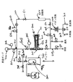
FIG. 1 is a diagram illustrating an embodiment of a system according to the concept of the present invention. As shown in the figure, this18In the F fluoride production system 1, an
[0017]
In the embodiment shown in FIG. 1, the valve is specifically a manual valve (eg, a bellows valve or other suitable valve) shown as
[0018]
The target reaction chamber 200 includes an irradiation
[0019]
In different embodiments, a cooling jacket (which is one example of a cooling device, but is not limited to this) forms part of the reaction chamber wall 202 (not shown in FIG. 1) or a heating tape (of the heating device). An example, but not limited to, forms part of the reaction chamber wall 202 (not shown in FIG. 1), or both. Preferably, the temperature of various parts of the reaction chamber 200 can be monitored, for example, by thermocouples (not shown in FIG. 1). The use of a cooling jacket18Allows cooling of the reaction chamber at various stages of F fluoride production. Use of heating tape18Allows heating of the reaction chamber at various stages of F fluoride production. A cooling jacket, heating tape or both can be used to control the temperature of the reaction chamber. Instead of a cooling jacket and a heating tape, other cooling devices and heating devices can be used. The cooling and heating devices can be located inside or outside the
[0020]
The reaction chamber 200 is connected to the
[0021]
18O inlet 601 is unused18First, a
[0022]
A method of implementing the inventive concept is described below with reference to FIG. 2 as one preferred method using the embodiment of FIG.
[0023]
First, the valves 501 to 513 are closed. Contaminants that may be present at the beginning of the first run or after prolonged storage and when it is unclear whether the contamination level has increased, preferably by evacuating the
[0024]
In step S1010,
[0025]
In step 1020, the reaction chamber
[0026]
In
18O + p →18F + n
Irradiation time is desired18F fluoride amount, proton beam flow, proton beam energy, reaction cross section and18It can be calculated based on well-known equations relating to the half-life of F fluoride. Table 1 shows the expected yield with a 100 microamp proton beam flow at different proton energies and different irradiation times. TTY is an abbreviation that represents the yield when the target is thick enough to completely absorb the proton beam.
[0027]
[Table 1]
TTY is an abbreviation for thick target yield. Where it is irradiated18Since the O gas is thick enough, that is, its pressure is sufficient, the total transmitted proton beam is18Absorbed by O. Yield is expressed in Curie units. "TTY at saturation" means that the yield is saturated18The yield of O gas when the irradiation time is long, that is, about 12 hours.
[0029]
Preferably,18O gas is at high pressure.18In order to make the O gas a thick target for the proton beam, the required length of the
[0030]
[Table 2]
As a result, in one preferred example, reaction chamber 200 (and portions thereof) is designed to withstand high pressures. This is especially because higher pressure is required as the reaction chamber 200 and gas are warmed by irradiation with the proton beam.18From O gas18In one example of the inventive concept of making F fluoride, we have 13 MeV (12.5 MeV protons that penetrate into the reaction chamber and a Huber vessel window absorbed by 20 microamps beam flow. A filling pressure of 20 atmospheres irradiated with 5 MeV protons).18We show success with a 40 micron thick hub containing O gas. In this example, during irradiation with a proton beam18O gas successfully contained, therefore18O gas has a temperature (pressure well above 100 ° C.) and pressure much higher than the filling temperature and pressure before irradiation. In another example, a cooling jacket (line) is used to remove heat from within the reaction chamber during irradiation. In a preferred example, the concept of the present invention is implemented at high pressure using a relatively short vessel length, thereby simplifying the requirements for the intensity of the incident proton beam. In another example, other suitable designs may be used at the desired pressure.18Used to contain O gas.
[0032]
18When F fluoride is produced, it adheres to the
[0033]
In step 1040, unused18O is removed from the
[0034]
In
[0035]
Preferably, the material used as the solvent adhered to the container part 20418F should be easily removed (physically and / or chemically) but preferably dissolved18It should easily allow uncontaminated separation of F fluoride. Also, each element of this system is preferably18Should not be corroded when F fluoride comes into contact. Examples of such solvents include, but are not limited to, water, acids and alcohols in the form of liquids or vapors, for example.19F is preferably not a solvent. Because the resulting mixture cannot be separated18F-19F molecule, and therefore the final obtained18Reduce the yield of F-fluoride based compounds.
[0036]
Table 3 was extracted with water at various temperatures18Various percentages of F fluoride are shown. Container parts using stainless steel produced 93.2% in two washes using 80 ° C. water.18This produces F fluoride. On the other hand, glass carbon was produced 98.3% in one wash with 80 ° C. water.18This produces F fluoride. The cleaning time was on the order of 10 seconds. Using higher temperature water is expected to improve the yield per wash. Steam generated18It is expected to operate at least as well as water, if not better, in the dissolution of F fluoride. Generated18Other solvents can be used in place of water, with the goal of dissolving F rapidly and not diluting the final compound based on fluorine.
[Table 3]
In
[0038]
[0039]
Separated in step 107018F fluoride is processed from
[0040]
In
[0041]
It should be noted that
[0042]
After drying the
[0043]
The experimental operation of the inventive concept is consistently18Theoretically obtainable from O18At least 70% of the F fluoride was produced. The equipment is equipped with a 15 ml reaction chamber,18O gas is filled to about 20 atmospheres, the proton beam is 13 MeV with a proton flow of 20 microamps, the solvent is deionized in a volume of 100 milliliters, and the QMA separator is 2 × 2 milliliters Extract with bicarbonate solution.18Hydrogen ions in O concentrated water against proton flow18In order to reduce the exposure of O18O is18Such a result is particularly important as it has a yield of 14-18% better than O-enriched water. This yield difference increases with decreasing proton energy. The difference in yield is 16%, 15.2%, 14.75% and 14.3% at 15, 30, 50 and 100 MeV, respectively. As a result, the concept of the present invention is18Rather than being able to produce with a system based on O-concentrated water,18Significantly increase the overall yield of F fluoride. For example, operating a simple (non-swept beam) system that embodies the concepts of the present invention with a proton flow beam of 100 microamperes and an energy of 15 MeV, a complex (swept) of Helmeke operating at nominally up to 30 microamperes. The overall yield was about 53% greater than the beam and larger target window) system.
[0044]
The concept of the invention can be embodied in a variant in which separate chemically inert gas outlets are used instead of one outlet to perform the various steps in parallel. The concept of the present invention can also be embodied by using a valve that separates the eluent outlet from the
[0045]
Although the invention has been described in considerable detail using a number of specific examples, it will be apparent that various modifications and applications of the invention may be made without departing from the scope of the invention. All such modifications apparent to those skilled in the art are intended to be included within the scope of the appended claims.
[Brief description of the drawings]
FIG. 1 is a general block diagram illustrating an embodiment of a system according to the present invention.
[Figure 2]18From O gas18General flow chart describing a method of using the embodiment of FIG. 1 to produce F fluoride
[Explanation of symbols]
100 loop tube, 200 reaction chamber, 201 inside reaction chamber, 202 window, 20418Parts to which F fluoride adheres, 400 vacuum pump, 800 container.
Claims (20)
18Fフッ化物が付着する少なくとも1つの部品を含む反応室の中に、18O気体の分子を入れ、
100μA以上のビーム流を有する陽子ビームで反応室内の18O気体を照射して、18O気体の一部を18Fフッ化物に変換し、変換された18Fフッ化物が前記の少なくとも1つの部品に付着し、
前記の反応室内で、前記の少なくとも1つの部品に付着する18Fフッ化物を溶解する溶媒に、前記の少なくとも1つの部品を露出する
方法。A method for producing 18 F fluoride from 18 O gas, comprising:
18 into the reaction chamber F fluoride comprising at least one component attached, put molecules 18 O gas,
By irradiating 18 O gas in the reaction chamber in the proton beam having a 100μA or more beam current, 18 O portion of the gas is converted into 18 F fluoride, it converted 18 F fluoride of said at least one component Adheres to
Exposing the at least one component in a solvent that dissolves the 18 F fluoride adhering to the at least one component in the reaction chamber.
18O気体を保持する容器と、
前記の容器に接続され、18O2 の気体を受け入れる反応室であって、陽子ビームに透明な少なくとも1つの壁を含み、18Fフッ化物が付着する少なくとも1つの部品を取り囲む反応室と、
陽子ビームに透明な前記の少なくとも1つの壁を通して、前記の反応室内で 18 Oを照射するための、少なくとも100μAのビーム流を有するの陽子ビームを生成する生成手段と、
前記の反応室に接続される溶媒入口であって、フッ化物溶液を作成するための、前記の少なくとも1つの反応室成分に付着される18Fフッ化物を溶解する溶媒を前記の反応室の中に導入するための溶媒入口と、
前記の反応室から前記のフッ化物溶液を除去するための溶媒出口と
からなることを特徴とするシステム。A system for producing 18 F fluoride from 18 O,
A container holding 18 O gas;
A reaction chamber connected to said vessel and receiving a gas of 18 O 2 comprising at least one wall transparent to the proton beam and surrounding at least one part to which 18 F fluoride is attached;
Through at least one wall of transparent the proton beam, for irradiating the 18 O in the reaction chamber of the, generation means for generating a proton beam has at least 100μA beam stream,
A solvent inlet connected to the reaction chamber, wherein a solvent for dissolving the 18 F fluoride attached to the at least one reaction chamber component for preparing a fluoride solution is contained in the reaction chamber. A solvent inlet for introduction into
A system comprising a solvent outlet for removing the fluoride solution from the reaction chamber .
Applications Claiming Priority (3)
| Application Number | Priority Date | Filing Date | Title |
|---|---|---|---|
| US18435200P | 2000-02-23 | 2000-02-23 | |
| US60/184,352 | 2000-02-23 | ||
| PCT/US2001/005608 WO2001063623A1 (en) | 2000-02-23 | 2001-02-23 | System and method for the production of 18f-fluoride |
Publications (3)
| Publication Number | Publication Date |
|---|---|
| JP2003524787A JP2003524787A (en) | 2003-08-19 |
| JP2003524787A5 JP2003524787A5 (en) | 2005-08-04 |
| JP3996396B2 true JP3996396B2 (en) | 2007-10-24 |
Family
ID=22676532
Family Applications (1)
| Application Number | Title | Priority Date | Filing Date |
|---|---|---|---|
| JP2001562717A Expired - Fee Related JP3996396B2 (en) | 2000-02-23 | 2001-02-23 | System and method for production of 18F fluoride |
Country Status (9)
| Country | Link |
|---|---|
| US (2) | US6845137B2 (en) |
| EP (1) | EP1258010B1 (en) |
| JP (1) | JP3996396B2 (en) |
| AT (1) | ATE430368T1 (en) |
| AU (2) | AU2001239816B2 (en) |
| CA (1) | CA2401066C (en) |
| DE (1) | DE60138526D1 (en) |
| MX (1) | MXPA02008280A (en) |
| WO (1) | WO2001063623A1 (en) |
Families Citing this family (34)
| Publication number | Priority date | Publication date | Assignee | Title |
|---|---|---|---|---|
| US6599484B1 (en) * | 2000-05-12 | 2003-07-29 | Cti, Inc. | Apparatus for processing radionuclides |
| AU2001274843A1 (en) * | 2000-05-17 | 2001-11-26 | The Regents Of The University Of California | Method for producing(18f)fluoride ion |
| US6567492B2 (en) * | 2001-06-11 | 2003-05-20 | Eastern Isotopes, Inc. | Process and apparatus for production of F-18 fluoride |
| EP1412951A2 (en) * | 2001-06-13 | 2004-04-28 | The Uni. Of Alberta, the Uni. of British Columbia, Carleton Uni., Simon Fraser Uni., the Uni. of Victoria, d.b.a. TRIUMF | Apparatus and method for generating ?18 f-fluoride by ion beams |
| US7018614B2 (en) * | 2002-11-05 | 2006-03-28 | Eastern Isotopes, Inc. | Stabilization of radiopharmaceuticals labeled with 18-F |
| WO2005014136A2 (en) * | 2003-08-08 | 2005-02-17 | Washington University In St. Louis | Enhanced separation process for (76br, 77br and 124i) preparation and recovery of each |
| US7831009B2 (en) * | 2003-09-25 | 2010-11-09 | Siemens Medical Solutions Usa, Inc. | Tantalum water target body for production of radioisotopes |
| US20050279130A1 (en) * | 2004-06-18 | 2005-12-22 | General Electric Company | 18O[O2] oxygen refilling technique for the production of 18[F2] fluorine |
| DE102005026253A1 (en) * | 2004-06-18 | 2006-01-05 | General Electric Co. | Generation of 18F (F2) fluorine from 18O (O2) oxygen in high yield |
| US20060023829A1 (en) * | 2004-08-02 | 2006-02-02 | Battelle Memorial Institute | Medical radioisotopes and methods for producing the same |
| US20060039522A1 (en) * | 2004-08-18 | 2006-02-23 | Research Foundation Of The State University Of New York | Cyclotron target, apparatus for handling fluids with respect thereto and for recovering irradiated fluids, and methods of operating same |
| GB0506041D0 (en) * | 2005-03-24 | 2005-04-27 | Ge Healthcare Ltd | Stripping method |
| GB2426862B (en) * | 2005-06-04 | 2007-04-11 | Alan Charles Sturt | Thermonuclear power generation |
| JP4099187B2 (en) * | 2005-09-30 | 2008-06-11 | 株式会社日立製作所 | Radioisotope production apparatus and target recycling method |
| JP4885809B2 (en) * | 2007-08-14 | 2012-02-29 | 住友重機械工業株式会社 | O gas recovery device and O gas recovery method |
| US20100243082A1 (en) * | 2007-10-31 | 2010-09-30 | Atomic Energy Council - Institute Of Nuclear Energy Research | Liquid isotope delivery system |
| KR100967359B1 (en) * | 2008-04-30 | 2010-07-05 | 한국원자력연구원 | Radioisotope production gas target with fin structure at the cavity |
| EP2294582B1 (en) | 2008-05-02 | 2018-08-15 | Shine Medical Technologies, Inc. | Device and method for producing medical isotopes |
| WO2012003009A2 (en) | 2010-01-28 | 2012-01-05 | Shine Medical Technologies, Inc. | Segmented reaction chamber for radioisotope production |
| US9177679B2 (en) * | 2010-02-11 | 2015-11-03 | Uchicago Argonne, Llc | Accelerator-based method of producing isotopes |
| US9336916B2 (en) | 2010-05-14 | 2016-05-10 | Tcnet, Llc | Tc-99m produced by proton irradiation of a fluid target system |
| JP5322071B2 (en) * | 2010-09-22 | 2013-10-23 | 独立行政法人放射線医学総合研究所 | Radionuclide production method and apparatus using accelerator |
| WO2012092394A1 (en) | 2010-12-29 | 2012-07-05 | Cardinal Health 414, Llc | Closed vial fill system for aseptic dispensing |
| US10734126B2 (en) | 2011-04-28 | 2020-08-04 | SHINE Medical Technologies, LLC | Methods of separating medical isotopes from uranium solutions |
| US9269467B2 (en) | 2011-06-02 | 2016-02-23 | Nigel Raymond Stevenson | General radioisotope production method employing PET-style target systems |
| WO2013012822A1 (en) | 2011-07-15 | 2013-01-24 | Cardinal Health 414, Llc | Systems, methods, and devices for producing, manufacturing, and control of radiopharmaceuticals |
| US9417332B2 (en) | 2011-07-15 | 2016-08-16 | Cardinal Health 414, Llc | Radiopharmaceutical CZT sensor and apparatus |
| WO2013012813A1 (en) | 2011-07-15 | 2013-01-24 | Cardinal Health 414, Llc | Modular cassette synthesis unit |
| RU2649662C2 (en) | 2012-04-05 | 2018-04-05 | Шайн Медикал Текнолоджиз, Инк. | Aqueous assembly and control method |
| WO2018002079A1 (en) * | 2016-06-28 | 2018-01-04 | ASOCIACIÓN CENTRO DE INVESTIGACIÓN COOPERATIVA EN BIOMATERIALES - CIC biomaGUNE | Pharmaceutical composition comprising fluorine-18 labelled gases |
| JP6274689B1 (en) * | 2016-11-16 | 2018-02-07 | 株式会社京都メディカルテクノロジー | RI-labeled compound manufacturing apparatus and RI-labeled compound manufacturing method |
| US10109383B1 (en) * | 2017-08-15 | 2018-10-23 | General Electric Company | Target assembly and nuclide production system |
| JP6873381B1 (en) * | 2020-12-19 | 2021-05-19 | 株式会社京都メディカルテクノロジー | 18F-labeled compound manufacturing apparatus and 18F-labeled compound manufacturing method |
| CN113955771A (en) * | 2021-10-29 | 2022-01-21 | 北京善为正子医药技术有限公司 | Automatic synthesis method for rapidly preparing 18F sodium fluoride PET (polyethylene terephthalate) medicine |
Family Cites Families (7)
| Publication number | Priority date | Publication date | Assignee | Title |
|---|---|---|---|---|
| CA1201222A (en) * | 1982-06-01 | 1986-02-25 | Robert Robertson | Gas-target method for the production of iodine-123 |
| DE3424525A1 (en) | 1984-07-04 | 1986-01-16 | Kernforschungsanlage Jülich GmbH, 5170 Jülich | METHOD FOR PRODUCING (ARROW UP) 1 (ARROW UP) (ARROW UP) 8 (ARROW UP) F-ALKYL AND ARYL COMPOUNDS BY HALOGEN EXCHANGE |
| JPH0778558B2 (en) * | 1990-07-20 | 1995-08-23 | 日本鋼管株式会社 | ▲ Up 13 ▼ NH ▲ Up + ▼ ▲ Down 4 ▼, ▲ Up 18 ▼ F-Target box for simultaneous production |
| US5280505A (en) * | 1991-05-03 | 1994-01-18 | Science Research Laboratory, Inc. | Method and apparatus for generating isotopes |
| US5425063A (en) * | 1993-04-05 | 1995-06-13 | Associated Universities, Inc. | Method for selective recovery of PET-usable quantities of [18 F] fluoride and [13 N] nitrate/nitrite from a single irradiation of low-enriched [18 O] water |
| US5468355A (en) * | 1993-06-04 | 1995-11-21 | Science Research Laboratory | Method for producing radioisotopes |
| US5917874A (en) * | 1998-01-20 | 1999-06-29 | Brookhaven Science Associates | Accelerator target |
-
2001
- 2001-02-23 EP EP01914426A patent/EP1258010B1/en not_active Expired - Lifetime
- 2001-02-23 JP JP2001562717A patent/JP3996396B2/en not_active Expired - Fee Related
- 2001-02-23 US US09/790,572 patent/US6845137B2/en not_active Expired - Fee Related
- 2001-02-23 AT AT01914426T patent/ATE430368T1/en not_active IP Right Cessation
- 2001-02-23 DE DE60138526T patent/DE60138526D1/en not_active Expired - Lifetime
- 2001-02-23 MX MXPA02008280A patent/MXPA02008280A/en active IP Right Grant
- 2001-02-23 AU AU2001239816A patent/AU2001239816B2/en not_active Ceased
- 2001-02-23 WO PCT/US2001/005608 patent/WO2001063623A1/en active IP Right Grant
- 2001-02-23 CA CA2401066A patent/CA2401066C/en not_active Expired - Fee Related
- 2001-02-23 AU AU3981601A patent/AU3981601A/en active Pending
-
2004
- 2004-11-19 US US10/991,552 patent/US20050129162A1/en not_active Abandoned
Also Published As
| Publication number | Publication date |
|---|---|
| EP1258010B1 (en) | 2009-04-29 |
| US6845137B2 (en) | 2005-01-18 |
| WO2001063623A1 (en) | 2001-08-30 |
| US20050129162A1 (en) | 2005-06-16 |
| ATE430368T1 (en) | 2009-05-15 |
| DE60138526D1 (en) | 2009-06-10 |
| MXPA02008280A (en) | 2004-04-05 |
| CA2401066C (en) | 2010-08-10 |
| JP2003524787A (en) | 2003-08-19 |
| CA2401066A1 (en) | 2001-08-30 |
| AU2001239816B2 (en) | 2005-01-27 |
| AU3981601A (en) | 2001-09-03 |
| EP1258010A1 (en) | 2002-11-20 |
| US20010043663A1 (en) | 2001-11-22 |
Similar Documents
| Publication | Publication Date | Title |
|---|---|---|
| JP3996396B2 (en) | System and method for production of 18F fluoride | |
| AU2001239816A1 (en) | System and method for the production of 18F-fluoride | |
| US4664869A (en) | Method for the simultaneous preparation of Radon-211, Xenon-125, Xenon-123, Astatine-211, Iodine-125 and Iodine-123 | |
| JP3989897B2 (en) | Apparatus and method for the production of 18F-fluoride by ion beam | |
| Blessing et al. | Production of [18F] F2, H18F and 18Faq− using the 20Ne (d, α) 18F process | |
| US11851383B2 (en) | Automatic process platform for the production of astatine-211 [At-211]-radiopharmaceuticals | |
| AU2002312677A1 (en) | Apparatus and method for generating 18F-fluoride by ion beams | |
| Iwata et al. | [18F] Fluoride production with a circulating [18O] water target | |
| JP6274689B1 (en) | RI-labeled compound manufacturing apparatus and RI-labeled compound manufacturing method | |
| JP4977335B2 (en) | 18 [F2] fluorine production system and 18O [O2] oxygen replenishment method for producing 18 [F2] fluorine | |
| KR100766568B1 (en) | System and method for the production of 18f-fluoride | |
| US4894208A (en) | System for separating radioactive NA from Al | |
| JP6873381B1 (en) | 18F-labeled compound manufacturing apparatus and 18F-labeled compound manufacturing method | |
| JP4238352B2 (en) | [11C] Method for synthesizing methyl halide | |
| RU2476942C1 (en) | Method of obtaining rhenium-188 radionuclide without carrier and apparatus for realising said method | |
| JP2828853B2 (en) | Acetic acid synthesis method | |
| JP4898152B2 (en) | High yield production of 18F [F2] fluorine from 18O [O2] oxygen | |
| US5875220A (en) | Process for production of radiostrontium | |
| JP2005053804A (en) | Method for producing [11c]ch3x | |
| Artyukhov et al. | A Laboratory Setup for Increasing the Technological Yield of 123I from a 124Xe Target under Proton Bombardment | |
| JPS6064934A (en) | Apparatus for automatic synthesis of methyl iodide | |
| Santos et al. | Production of 18 F using a natural water target at the CV-28 cyclotron at IPEN-CNEN/SP |
Legal Events
| Date | Code | Title | Description |
|---|---|---|---|
| A131 | Notification of reasons for refusal |
Free format text: JAPANESE INTERMEDIATE CODE: A131 Effective date: 20061226 |
|
| A601 | Written request for extension of time |
Free format text: JAPANESE INTERMEDIATE CODE: A601 Effective date: 20070326 |
|
| A602 | Written permission of extension of time |
Free format text: JAPANESE INTERMEDIATE CODE: A602 Effective date: 20070402 |
|
| A521 | Request for written amendment filed |
Free format text: JAPANESE INTERMEDIATE CODE: A523 Effective date: 20070626 |
|
| TRDD | Decision of grant or rejection written | ||
| A01 | Written decision to grant a patent or to grant a registration (utility model) |
Free format text: JAPANESE INTERMEDIATE CODE: A01 Effective date: 20070724 |
|
| A61 | First payment of annual fees (during grant procedure) |
Free format text: JAPANESE INTERMEDIATE CODE: A61 Effective date: 20070802 |
|
| FPAY | Renewal fee payment (event date is renewal date of database) |
Free format text: PAYMENT UNTIL: 20100810 Year of fee payment: 3 |
|
| R150 | Certificate of patent or registration of utility model |
Free format text: JAPANESE INTERMEDIATE CODE: R150 |
|
| FPAY | Renewal fee payment (event date is renewal date of database) |
Free format text: PAYMENT UNTIL: 20100810 Year of fee payment: 3 |
|
| LAPS | Cancellation because of no payment of annual fees |