JP3992908B2 - Transmission apparatus using orthogonal frequency division multiplexing modulation system - Google Patents
Transmission apparatus using orthogonal frequency division multiplexing modulation system Download PDFInfo
- Publication number
- JP3992908B2 JP3992908B2 JP2000192311A JP2000192311A JP3992908B2 JP 3992908 B2 JP3992908 B2 JP 3992908B2 JP 2000192311 A JP2000192311 A JP 2000192311A JP 2000192311 A JP2000192311 A JP 2000192311A JP 3992908 B2 JP3992908 B2 JP 3992908B2
- Authority
- JP
- Japan
- Prior art keywords
- carrier
- synchronous
- carrier section
- section
- reference signal
- Prior art date
- Legal status (The legal status is an assumption and is not a legal conclusion. Google has not performed a legal analysis and makes no representation as to the accuracy of the status listed.)
- Expired - Lifetime
Links
Images


Landscapes
- Detection And Prevention Of Errors In Transmission (AREA)
Description
【0001】
【発明の属する技術分野】
本発明は、伝送方式として、互いに直交する複数本の搬送波(キャリア)で情報符号を伝送する直交周波数分割多重変調方式(Orthogonal Frequency Division Multiplexing:以下OFDM方式と記す)を用いた伝送装置であって、この複数本のキャリアを複数のキャリア区に分離し、各キャリア区を変調する変調方式を各キャリア区毎に設定できる伝送装置に関する。
【0002】
【従来の技術】
近年、無線装置の分野では、マルチパスフェージングに強い変調方式として、OFDM方式が脚光を集め、欧州や日本を初めとする各国の次世代のテレビ放送、FPU(Field Pick-up Unit)、無線LAN等の分野で多くの応用研究が進められている。 この内、UHF帯の地上波ディジタル放送の開発動向と方式については、「映像情報メディア学会誌」1998 Vol.52,No.11に、詳しく開示されている。
従来例として、日本のUHF帯の地上波ディジタル放送方式のシステム構成を取り上げて説明する。 但し、このシステムは、非常に複雑な構成であるため、ここでは、本発明の理解に必要な範囲について簡単化して説明する。
図4はこの放送システムのキャリア構造を説明する図である。 約1400本のキャリアは、13セグメントの区に分割されている。
伝送する信号としては、3チャンネル(3階層)の情報符号まで同時に伝送でき、各階層が使用するセグメント数と変調方式を自由に選択できる。
ここで、変調方式としては、同期検波を用いる変調方式(同期変調方式)と差動検波を用いる変調方式(差動変調方式)が用意されている。 但し、差動変調方式で変調されたキャリアは、図5のように帯域の中心部のセグメントに配置され、同期変調方式で変調されるキャリアは、その外側のセグメントに配置される。
同時に伝送する階層数は、1から3階層の中から自由に選択できる。
図5は、A階層を4相差動位相偏移変調(DQPSK:Differential Quadrature Phase Shift Keying)方式、B階層を16値直交振幅変調(16QAM:16 Quadrature Amplitude Modulation)方式、C階層を64値直交振幅変調(64QAM:64 Quadrature Amplitude Modulation)方式で変調して伝送する場合の一例である。
【0003】
ここでは、本発明が、上記変調方式の内の同期変調方式で伝送される情報符号の符号誤り率の低減に関するものであるため、同期変調方式、例えば64QAMで変調するキャリア部分の構造について更に詳しく説明する。
図6は、同期変調方式で変調するセグメントのキャリア構造を更に詳しく説明する図である。
ここで、1階層の情報符号の伝送に全セグメントを使用するモードの場合は、同様の構造がその帯域内に渡って繰り返されると考えて良い。
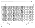
図6において、横方向は周波数、縦方向は時間の経過を表し、横と縦の方向に並んだ四角印「□」は、それぞれが1つのキャリアを表す。 従って、縦方向に並ぶ四角印「□」の1列が、OFDM信号を構成する1つのシンボルを表す。
SPと書かれた四角印「□」は、復調の際の基準信号を再生するのに用いられるパイロット信号の位置を示している。 また、何も書かれていない「□」は、64QAMで変調された信号位置を表している。
ここで、パイロット信号は周波数方向と時間方向にばらまかれた配置になっているため、SP(Scattered Pilot)と銘々されている。
ただし、図6はSPの配置を模式的に示しただけであり、本来であれば記載しなければならない、制御信号伝送用のTMCC(Transmission and Multiplexing Configuration Control)キャリア、付加情報AC(Auxiliary Channel)キャリアは、省略してある。
また、地上波ディジタル放送方式では時間方向にSPがあるキャリアの横方向の間隔は3本間隔であるのに対し、図6では5本間隔に変更してある。 これは後述の本発明の説明を表現し易いように変更したものであって、本質的な内容は変わらない。 つまり、図6は、従来方式の1つのバリエーションと考えることができる。
【0004】
ところで、64QAM方式の信号点は、図7の直交座標面に破線の丸印「○」で示す64個の信号点で構成され、各信号点はそれぞれ6ビットからなる、互いに異なる符号列に対応させられている。
64QAM方式による変調処理は、入力された符号列を6ビット単位に分割し、上記64個の信号点の中から分割した各6ビットの符号に対応する信号点、例えば実線の丸印「○」の信号点を選択し、選択された信号点に対応する変調信号を出力することで実施される。
一方、受信された変調信号は、伝送される過程で雑音、その他の影響を受けて歪み、受信信号の信号点は、例えば、図7の実線の丸印「○」の位置からバツ印「×」の位置に移動してしまう。
64QAMの復調処理は、図7の破線の丸印「○」で示す64QAMの信号点の中から、バツ印「×」で示す受信信号の信号点に最も近い信号点を選択し、選択した信号点に対応する6ビットの符号を出力することによって実施される。
この復調処理を実施するには、受信信号に対する破線の「○」の正しい信号点位置を知る必要があるが、その位置を再生するには、例えば図7の信号空間上の座標点aの正確な位置を表す基準信号ベクトルの向きと大きさが分かればよい。
【0005】
ところで、受信信号の基準信号ベクトルの向きと大きさは、伝送系で発生するマルチパス等の影響を受け、図8のように位相が回転し振幅も変化してしまう。
このように基準信号ベクトルの位相と大きさは、各時間あるいは各キャリア毎に変化するが、その変化の仕方は通常滑らかな曲線を描き、時間方向とキャリア方向に強い相関を持つ。 そのため、図6の任意のシンボルの任意のキャリアの変調信号Aに対する基準信号ベクトルは、まばらに伝送された複数のSP信号を内挿して求めることができる。 図6では、この内挿演算を効率的に実施できるようにSPを配置している。
図6のキャリア構造の信号から基準信号ベクトルを再生する方法については、地上波ディジタル放送方式には特に規定はない。 しかし、例えば、図9に示す回路で実現できる。
【0006】
図9はOFDM方式の受信装置の基準信号ベクトルを再生する回路部分を抜き出したものである。
高速フーリエ変換回路(FFT:Fast Fourier Transform)5から出力された受信信号は、時間方向内挿回路6と遅延回路7に入力される。 この内、時間方向内挿回路6では、図10に斜線で示すように、時間方向にパイロット信号SPを含むキャリア毎に所定のタップ数のLPFに通し、時間方向に内挿された基準信号ベクトル信号として出力する。 このSPが配置されているキャリアを、以後、SPキャリアと記す。
【0007】
図11は、図6の一点鎖線3のキャリアを取り上げ、上記の時間方向の内挿方法を模式的に示したものである。 横軸は時間軸でありシンボル毎に目盛を付してある。 ○印を付した縦線は、受信されたSPの信号ベクトルを表している。ここで、或るSP、例えばSP1が受信された後、次のSP2が受信されるまでの間のシンボルの基準信号ベクトル信号は、時間的に前後する位置にある複数のSPの信号ベクトルを用い、一定タップ数のLPFにより内挿して求める。
この時間方向の内挿演算により、図10の斜線を付した5本間隔のキャリアの基準信号ベクトルが算出される。 この時、LPFの演算では、タップ数と同じシンボル数の信号が必要になり、内挿信号はタップ数の約半分のシンボル数遅れて出力される。
遅延回路7は、受信信号のタイミングをこの内挿信号のタイミングに合わせるために挿入した回路である。
【0008】
一方、図6のSPが配置されていないキャリアにある変調信号Aの基準信号ベクトルは、SPキャリアの基準信号ベクトルをキャリア方向に内挿して求める。図9のキャリア方向内挿回路8は、この内挿演算を実施する回路である。
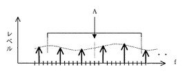
図12は、図10の一点鎖線4のシンボルを取り上げ、上記のキャリア方向の内挿方法を模式的に示したものである。 横軸は周波数軸であり、キャリア位置毎に目盛を付してある。 太い矢印は時間軸方向に内挿して求めた図10の斜線を付したキャリアの基準信号ベクトルW(1),W(5+1),W(2×5+1),・・・を表している。 ここで、括弧内の数字はキャリア番号である。
太い矢印の無いキャリア位置Aの基準信号ベクトルは次の様にして算出する。まず、図12の太い矢印が無いキャリアのベクトルの大きさを0として得られる信号W(1),0,・・,0,W(5+1),0,・・,0,W(2×5+1),・・・・を、例えばタップ数23タップの通常のディジタルLPFに通すことによって、破線で表す滑らかな内挿信号を算出する。 この様にして算出した内挿信号を、変調信号Aの基準信号ベクトルとして出力する。
キャリア方向内挿回路8で再生された基準信号ベクトル信号と、遅延回路7でタップ数の約半分のシンボル数だけ遅延された受信信号は、64QAM復調回路9に入力され、図8のように変形した信号点位置を、図7の正しい位置に直すことにより、情報符号を復調することができる。
【0009】
【発明が解決しようとする課題】
ところで、このようにキャリア方向の相関を利用する基準信号ベクトルの再生方法では、次のような問題が生じる。 すなわち、キャリア方向の内挿に用いるディジタルLPFは、例えばタップ数23タップを持つフィルタであり、任意のキャリア番号の内挿値を求めるには、図12に示す様に、例えば、そのキャリアの前後11キャリア分の信号が必要になる。
ここで、帯域の中程にあるキャリアに対する内挿値を算出する際は、その前後に、必要な本数のキャリアが必ずあるので問題は生じない。
しかし、このフィルタの特性を検討する過程で、この内挿演算の処理において、以下のような問題が内在することになる。 即ち、帯域の境界近傍では、状況が上記の状況と異なると言う点である。
図13に示すように、帯域の境界近傍では、内挿値を求めようとしているキャリア位置の一方側、図13の場合は低周波数側にはキャリアが存在しなくなる。
即ち、この場合、正しい内挿演算が実施されるのに必要な、太い破線の矢印で示す基準信号ベクトルが存在しないので、正しい内挿値が得られなくなる。
ここで、本来あるべき基準信号ベクトルと内挿値との差である歪みベクトルの大きさを図示すると、図14のようになる。 この図では、周波数軸上のキャリア位置に目盛が付してあり、SPキャリアの位置には、周波数軸上に丸印「○」が付してある。
【0010】
この図14から、キャリア方向の内挿値の正しい基準信号ベクトルからの歪みは、キャリア方向の内挿に用いるディジタルLPFのタップ数のほぼ1/2のキャリア本数の範囲で、キャリアが帯域の端に近づくに従って急激に増加していることが分かる。
例えば、一番端のSPキャリア10と2番目のSPキャリア11の間のキャリアにおいては、伝送系で混入するマルチパスの条件によっては、正しい基準信号ベクトルの大きさの1/7を越える歪みが生じることになる。
ここで発生する歪みには基準信号ベクトルの方向を回転させる成分と大きさを変える成分があるが、何れにしてもこの基準信号ベクトルに対する歪みの影響は以下に説明するように非常に大きい。
例えば図15は、基準信号ベクトルの大きさに約1/7の歪みが生じた場合の信号点のずれを示したもので、内挿演算で求めた基準信号ベクトルから算出した信号点は実線の丸印「○」で表され、正しい基準信号ベクトルから算出される信号点は破線の丸印「○」で表されている。
図15から明らかなように、この場合、例え正しい信号点Bの近傍にあるバツ印「×」の位置で信号が受信されたとしても、隣の信号点Cと誤って復調されてしまうことになり、非常に高い頻度で、符号誤りが発生する。
【0011】
例えば変調方式が64QAM、キャリア本数が1400本のOFDMにおいては、帯域の端で基準信号ベクトルに大きな歪みが発生してしまうキャリアの本数が、両サイド合わせて僅か約6本であったとしても、システム全体としての符号誤り率は、6/(1400×6)=約1×10-3程度にも達してしまう。
これでは、ビタビ復号等の誤り訂正を施すシステムの場合には、到底対応できない。 つまり、このような誤り訂正を施した場合、誤り訂正前の符号誤り率は、通常、10-3程度以下の性能が要求されるからである。 なお、ここでは、帯域の端にある6本のキャリアは信号点に対応する6ビットの符号の内の1ビットのみ誤るものとする。
また、この6本のキャリアは必ず誤るとしている。 なお、この6本のキャリアで伝送する符号によっては誤りを生じない場合もある。 しかし、この点を考慮しても、符号誤り率は1×10⁻³から1×10⁻⁴程度の、かなり高い頻度で符号誤りが発生する。
この符号誤りは、マルチパスが有ると、受信信号に全く雑音が含まれていない場合でも生じる。 これは、受信状態を改善しても、符号誤り率を一定値以下に下げられないことを意味する。
つまり、再生された基準信号ベクトルにこの様に大きな歪みが生じるか否かは、伝送系で混入するマルチパス成分の大きさと遅延時間に依存するもので、常時、発生するものではないが、上記のような従来技術が、伝送系の環境の変化に非常に弱いシステムになることに変わりはない。
本発明は、これらの欠点を除去し、大きな規模の回路を用いることなく、伝送系の環境の変化にも強く、同期変調方式による良好なOFDM方式の伝送装置を提供することを目的とする。
【0012】
【課題を解決するための手段】
本発明は上記の目的を達成するため、位相が互いに直交する複数本のキャリアを用いて情報符号を伝送する直交周波数分割多重変調方式の伝送装置であって、上記複数本のキャリアを複数のキャリア区に分割し、当該各キャリア区毎に所定の変調方式を用いる伝送装置において、上記複数のキャリア区中に、同期検波による変調方式(同期変調方式)を用いる所定のキャリア区を挟んでその周波数帯域の両側に、当該同期変調方式の多値数が異なるかあるいは当該所定のキャリア区で用いられる誤り訂正符号と訂正能力が異なる同期変調方式のキャリア区を、少なくとも1つ以上連続して割り当てるようにしたものである。
また、上記連続して割り当てられる同期変調方式のキャリア区の周波数帯域の両側に、少なくとも差動検波による変調方式(差動変調方式)を用いるキャリア区を割り当てるようにしたものである。
更に、上記連続して割り当てられる同期変調方式のキャリア区の内の最も外側のキャリア区には、当該キャリア区の内側に位置するキャリア区を変調する同期変調方式の多値数より低い多値数か、あるいは当該キャリア区の内側に位置するキャリア区で用いられる誤り訂正符号より訂正能力が高い誤り訂正符号を用いるキャリア区を割り当てるようにしたものである。
また、位相が互いに直交する複数本のキャリアを用いて情報符号を伝送する直交周波数分割多重変調方式の伝送装置であって、上記複数本のキャリアを複数のキャリア区に分割し、当該各キャリア区毎に所定の変調方式を用いる伝送装置において、上記複数のキャリア区中に、同期検波による変調方式を用いる所定のキャリア区(同期式キャリア区)を挟んでその周波数帯域の両側に、少なくとも差動検波による変調方式を用いるキャリア区(差動式キャリア区)を割り当て、当該差動式キャリア区内に、上記同期式キャリア区内に設けられた基準信号の再生に用いるパイロット信号と同じ間隔のパイロット信号を伝送するキャリアを設けるようにしたものである。
更に、上記差動式キャリア区内に設けられるパイロットキャリアは、上記同期式キャリア区との境界部分から所定の範囲内に、当該境界部分における基準信号ベクトルの内挿演算に必要とする本数分、挿入されるようにしたものである。
【0013】
その結果、本発明によるOFDM方式の伝送装置によれば、同期変調方式で変調して伝送する情報符号の符号誤り率を低減できる効果が得られる。
即ち、本発明のOFDM方式の伝送装置は、同期検波による変調方式を用いる所定のキャリア区を挟んでその周波数帯域の両側に、当該同期変調方式の多値数が異なるかあるいは当該所定のキャリア区で用いられる誤り訂正符号と訂正能力が異なる同期変調方式のキャリア区を、少なくとも1つ以上連続して割り当て、しかも、この連続するキャリア区の内の最も外側のキャリア区には、内側に位置するキャリア区の多値数より低い多値数か、内側に位置するキャリア区で用いられる誤り訂正符号より訂正能力が高い誤り訂正符号を用いるキャリア区を割り当てている。
連続したキャリア区の最も外側にあって多値数が低い同期変調方式は、その内側にあって多値数が高い同期変調方式に比べ、基準信号ベクトルの歪みの影響を受け難い。 特に、多値数の高いキャリア区は、基準信号ベクトルに歪みが生じない連続したキャリア区の内部にある。 そのため、基準信号ベクトルの歪みの影響を無視することができるようになる。 つまり、各キャリア区の変調方式を全く任意に選んで伝送する従来方式に比べ、同期変調方式で伝送する情報符号の符号誤り率を低減することができる。 なお、訂正能力が高い誤り訂正符号を用いても、基準信号ベクトルの歪みの影響を受け難く、同様の効果が得られる。
また、本発明のOFDM方式の伝送装置では、同期検波による変調方式を用いる所定のキャリア区(同期式キャリア区)を挟んでその周波数帯域の両側に、少なくとも差動検波による変調方式を用いるキャリア区(差動式キャリア区)を割り当て、当該差動式キャリア区内に、上記同期式キャリア区内に設けられた基準信号の再生に用いるパイロット信号と同じ間隔のパイロット信号を伝送するキャリアを設けている。 そのため、同期式キャリア区の境界付近においてもパイロット信号がなくならず、再生する基準信号ベクトルに歪みが生じることがなく、同期式キャリア区で伝送する情報符号の符号誤り率を大幅に低減することができる。この時、差動式キャリア区内のキャリア位置に対して再生された基準信号ベクトルには、従来と同じ歪みが発生する。 しかし、差動変調方式で変調された信号の復調では基準信号ベクトルを用いる必要がない。 従って、差動式キャリア区で伝送される情報符号の符号誤り率には何ら影響が生じない。
【0014】
【発明の実施の形態】
以下、本発明による直交周波数分割多重変調伝送装置について、図示の実施例により詳細に説明する。
図1は、本発明の第1の実施例における複数のキャリア区構造の一例を示すもので、複数本のキャリアを単位としてブロック化し、模式的に示している。
図1に示す様に、伝送帯域Wの中央部分には、最も多値数が高い、例えば64QAMの同期変調方式で変調された第1のキャリア区12が形成されている。
そして、このキャリア区12を挟んでその両側に連続して位置するキャリア区13とキャリア区14は、キャリア区12より多値数が低い、例えば16QAMの同期変調方式で変調された第2と第3のキャリア区である。 ここで、これら同期変調方式で変調されたキャリア区を、以下、同期式キャリア区とも称す。
この様に本実施例は、異なる同期変調方式で変調された複数のキャリア区が、連続したキャリア区を形成する構成である。 なお図1では、キャリア区13の外側に、DQPSKの様な差動変調方式で変調されたキャリア区(以下、差動式キャリア区とも称す)15が形成されているが、以下に説明する本実施例の効果は、差動式キャリア区の有無に拘わらず成り立つものである。 ここで、図1の各キャリア区のブロック内に記された64,16,Dは、それぞれ、64QAM,16QAM,DQPSK変調方式で変調されたキャリア区のブロックであることを表している。
なお本実施例においても、キャリア区15とキャリア区13の境界部b、及びキャリア区14とその外側の帯域外の領域との境界部cで、再生された基準信号ベクトルに生じる歪み状況は、従来の方法の場合と何ら変わらない。 つまり、それぞれの境界部では、再生された基準信号ベクトルに、図14に示すものと同じ歪みが発生する。
【0015】
また、図1に示すキャリア構造は、OFDM信号のN本のキャリアを、複数のキャリア区に分離し、各キャリア区毎に異なる変調方式で変調する点においては、図5に示す従来の地上波ディジタル放送方式のキャリア構造と同じである。
ただし、図5の従来のキャリア構造では、同期変調方式のキャリア区を、伝送帯域の中心部を除く任意の位置に配置するキャリア構造である。
つまり、図5の従来のキャリア構造では、64QAMで変調されたセグメント(キャリア区)の一方は、パイロット信号が存在しない伝送帯域外の領域に、直接接することになる。
これに対して図1の本実施例では、パイロット信号が存在しない領域に接しているのは、多値数が低い16QAMで変調されたキャリア区13,14であり、多値数が高い64QAMで変調されたキャリア区12は、多値数は低いが、パイロット信号が存在する16QAMで変調された2つのキャリア区の間に位置するよう配置されている点が、従来のキャリア構造と異なる。
即ち本実施例は、伝送帯域の最も外側に位置するキャリア区(最外キャリア区)は、例えば、16QAMによって変調されており、その内側に位置するキャリア区(内部キャリア区)は、例えば、64QAMによって変調されていると言う様に、最外キャリア区のキャリアを変調する変調方式を、内部キャリア区のキャリアを変調する同期変調方式の多値数より低い多値数の同期変調方式で変調するものとしている点が、従来の図5のキャリア構造と異なるものである。
【0016】
この様に、本実施例では、多値数の大きさに応じて複数のキャリア区の配置を設定しているため、多値数が高い64QAMで変調されるキャリア区12の両側には、キャリア区12と同じ間隔でパイロット信号が挿入されている16QAMで変調されたキャリア区13,14が、必ず存在することになる。
そのため、多値数が高い同期変調方式である64QAMで変調されているキャリア区12の境界部dでは、再生された基準信号ベクトルに歪みが生じない。
従って、多値数が高い64QAMで変調されているキャリア区12で伝送された情報符号は、歪みなく再生された基準信号ベクトルを用いて復調することができ、符号誤り率の低い情報符号を復調することができる。
一方、16QAMで変調されたキャリア区13,14の復調で用いる基準信号ベクトルには、従来と同じ歪みが残ることになる。 しかしながら、ここで用いられている変調方式(16QAM)の多値数は、内側のキャリア区12の同期変調方式(64QAM)の多値数より低く、基準信号ベクトルの歪みに強い。
そのため、総合的にみると、基準信号ベクトルの歪みの影響が少ない伝送装置を構成することができる。
この様に本実施例によるキャリア区の構造を用いると、多値数が高い同期変調方式で変調されている情報符号の復調符号の符号誤り率を低減できる効果が得られる。 また、総合的にも符号誤り率の少ない、同期変調方式を用いた伝送装置を構成することができる効果が得られる。
【0017】
次に本発明による第2の実施例を第1の実施例と同じ図1を用いて説明する。第1の実施例との違いは、連続する複数のキャリア区の内、内部キャリア区12で伝送される情報符号に用いる誤り訂正符号としては、例えば3/4の畳み込み符号を用い、キャリア区13,14で伝送される情報符号に用いる誤り訂正符号としては、キャリア区12で用いる誤り訂正符号より誤り訂正能力の高い、例えば1/2の畳み込み符号を用いる点にある。 ここで、キャリア区13,14の変調方式も、キャリア区12と同じ64QAMとしても良い。 なお、図1にはキャリア区13とキャリア区14を16QAMで変調する場合を記してあるが、以下の説明では、キャリア区13とキャリア区14も64QAMで変調するものとして説明する。
本実施例では、誤り訂正前の復調符号の符号誤り率は、図5の従来のキャリア区構造における、64QAMで変調したキャリア区の誤り訂正前の符号誤り率と同じである。
しかしながら、誤り訂正前の符号が符号誤りを起こし易いキャリア区の境界bと境界cのキャリアは、誤り訂正能力が高い1/2畳込み誤り訂正符号を用いたキャリア区13とキャリア区14内のキャリアである。
そのため、誤り訂正後の復号した情報符号の符号誤り率は、図5に示す従来の複数のキャリア区を任意に配置した場合に比べて、低減できる効果が得られる。
従って、総合的に符号誤り率の少ない、同期変調方式を用いた伝送装置を構成することができる効果が得られる。
この様に、第2の実施例においても、第1の実施例と同様に、同期変調方式で変調されている信号を復号して得た情報符号の符号誤り率を、低減できる効果が得られる。 また、総合的にも符号誤り率の少ない、同期変調方式を用いた伝送装置を構成することができる効果が得られる。
【0018】
次に、本発明による第3の実施例におけるキャリア区構造の一例を図2に示し、以下詳しく説明する。
本実施例においては、図2に示す様に、伝送帯域Wの中央部分には、多値数が高い、例えば、64QAMの同期変調方式で変調された同期式キャリア区16が形成されている。 そして、この同期式キャリア区16を挟んで、その両側に、第1の差動式キャリア区17と第2の差動式キャリア区18が配置されている。
本実施例では更に、同期式キャリア区16の内部に設けられたパイロット信号と同じ間隔のパイロット信号を伝送するキャリアを、隣接する差動式キャリア区17,18の内部に設けるキャリア構成としたものである。
図3は、図2の差動式キャリア区17と同期式キャリア区16の境界部分eのキャリア構造を拡大して示したもので、図6の従来技術の場合と同じく、横方向は周波数、縦方向は時間の経過を表し、横と縦の方向に並んだ四角印「□」は、それぞれが1つのキャリアを表している。 従って、縦方向に並んだ四角印「□」は、OFDM信号を構成する1つのシンボルを表す。
SPと記された四角印「□」は、復調の際の基準信号を再生するのに用いられるパイロット信号の位置を示している。 また、何も記されていない「□」は、64QAMで変調された信号位置を表している。 Dと記された四角印「□」は、そのキャリアをDQPSK,8DPSK,16DAPSK等の復調に基準信号ベクトルを必要としない差動変調方式で変調された信号位置を表している。
即ち、Dと記された「□」が並ぶ領域が差動式キャリア区であり、何も記されていない「□」とSPと記された「□」が並ぶ領域が同期式キャリア区である。
また、時間方向の内挿演算により基準信号ベクトルを求めるSPキャリアには、図10と同様に斜線を付してある。
【0019】
ここで、SPキャリア19は、従来と同様に同期式キャリア区(図2の16)の内部に設けられたSPキャリアである。 SPキャリア20は、差動式キャリア区(図2の17)の内部に新たに設けたSPキャリアであり、SPキャリア19と同じ間隔で差動式キャリア区の内部に挿入されるものである。
本実施例の様に、差動式キャリア区内部にもSPキャリアを設けておくことによって、基準信号ベクトルを再生するときの実効的な帯域が広がったのと等価になる。
即ち、第3の実施例では、同期式キャリア区の外側に、SPキャリアが設けられた差動式キャリア区が配置されているため、図14のように大きな歪みが発生することになる帯域の境界部は、同期式キャリア区には存在しなくなり、大きな歪みが発生しなくなる。
従って、第3の実施例によれば、同期式キャリア区により伝送される情報符号の符号誤り率を大幅に低減することができる。
なお、この代償として差動式キャリア区の情報符号を伝送するキャリア本数がSPキャリア本数分減り、伝送レートの低下を招くことになる。 しかし、挿入されるSPキャリアの本数は、数本程度あれば充分効果が得られるものである。
通常、この差動式キャリア区を構成するキャリア本数は100本から数百本で構成されることを考慮すると、情報符号の伝送レートの低下は、ほとんど問題にならないものである。
【0020】
ここで、この差動式キャリア区に挿入されるSPキャリアは、同期式キャリア区との境界部から所定の範囲内に、例えば、境界部における基準信号ベクトルの内挿演算に必要とされる本数分、挿入されていれば充分である。 勿論、回路構成を簡単にするため、差動式キャリア区の全体に、同期式キャリア区の内部に設けられたSPキャリアと同じ間隔で、SPキャリアを挿入しても良い。 但し、この場合は、差動式キャリア区において伝送する情報符号の伝送レートを下げることになる。
ここで、挿入されるSPキャリアが、上記境界部における基準信号ベクトルの内挿演算に必要とされる本数より少ないと、前述のように、基準信号ベクトルに歪みが残ることになる。 しかし、SPキャリアが上記境界部から、順に正しく挿入されていれば、その本数に応じて、図14に示す割合で歪み量を低減できる効果が得られる。
この様に、本実施例による同期方式キャリア区の構造と差動式キャリア区内部のキャリア構造を用いると、同期変調方式で変調されている情報符号の符号誤り率を大幅に低減でき、良好なる同期変調方式を用いた伝送装置を構成することができる。
【0021】
【発明の効果】
以上説明したように、本発明によれば、同期変調方式で変調されている信号を復号して得た情報符号の符号誤り率を、大幅に低減することができる。 また、総合的にも符号誤り率の少ない、同期変調方式を用いた伝送装置を構成することができる。
【図面の簡単な説明】
【図1】本発明によるOFDM伝送装置のキャリア区構造の一実施例を示す模式図
【図2】本発明によるOFDM伝送装置のキャリア区構造の他の実施例を示す模式図
【図3】図2のキャリア区構造の他の実施例におけるキャリア配置の一例を示す模式図
【図4】地上波ディジタル放送方式におけるキャリア構造の一例を説明する模式図
【図5】地上波ディジタル放送方式におけるキャリア区構造の一例を説明する模式図
【図6】地上波ディジタル放送方式におけるキャリア配置の一例を説明する模式図
【図7】64QAM方式における信号点配置を説明する模式図
【図8】受信側における受信信号の信号点の位置、位相変化を説明する模式図
【図9】従来の受信装置の基準信号ベクトル再生部の構成を示すブロック図
【図10】地上波ディジタル放送方式におけるキャリア配置の一例を説明する模式図
【図11】キャリアの時間方向の内挿状況を説明する模式図
【図12】キャリアの周波数方向の内挿状況を説明する模式図
【図13】キャリアの周波数方向の内挿演算における問題点を説明する模式図
【図14】キャリアの周波数方向の内挿による歪み量を説明する特性図
【図15】大きな歪みが生じた時の信号点の位置ずれを説明する模式図
【符号の説明】
1,2:SP、5:FFT回路、6:時間方向内挿回路、7:遅延回路、8:キャリア方向内挿回路、9:64QAM復調回路、10,11:SPキャリア、12,13,14,16:同期式キャリア区、15,17,18:差動式キャリア区、19:同期式キャリア区内部のSPキャリア、20:差動式キャリア区内部に設けたSPキャリア。[0001]
BACKGROUND OF THE INVENTION
The present invention is a transmission apparatus using an orthogonal frequency division multiplexing (hereinafter referred to as OFDM), which transmits an information code using a plurality of carriers orthogonal to each other as a transmission method. The present invention relates to a transmission apparatus capable of separating a plurality of carriers into a plurality of carrier sections and setting a modulation scheme for modulating each carrier section for each carrier section.
[0002]
[Prior art]
In recent years, in the field of wireless devices, the OFDM method has attracted attention as a modulation method that is resistant to multipath fading. Next-generation television broadcasting, FPU (Field Pick-up Unit), wireless LAN, and other countries in Europe and Japan Many applied researches are underway in these fields. Among these, the development trend and method of UHF band terrestrial digital broadcasting are described in “The Journal of the Institute of Image Information and Television Engineers” 1998 Vol. 52, no. 11 is disclosed in detail.
As a conventional example, a system configuration of Japanese UHF band terrestrial digital broadcasting will be described. However, since this system has a very complicated configuration, a range necessary for understanding the present invention will be described in a simplified manner.
FIG. 4 is a diagram for explaining the carrier structure of this broadcasting system. About 1400 carriers are divided into 13 segments.
As a signal to be transmitted, up to 3 channels (3 layers) of information codes can be transmitted simultaneously, and the number of segments and the modulation method used by each layer can be freely selected.
Here, as a modulation method, a modulation method using synchronous detection (synchronous modulation method) and a modulation method using differential detection (differential modulation method) are prepared. However, the carrier modulated by the differential modulation method is arranged in the central segment of the band as shown in FIG. 5, and the carrier modulated by the synchronous modulation method is arranged in the outer segment.
The number of layers to be transmitted simultaneously can be freely selected from 1 to 3 layers.
FIG. 5 shows a four-phase differential phase shift keying (DQPSK) system for the A layer, a 16-value quadrature amplitude modulation (16QAM) system for the B layer, and a 64-value quadrature amplitude for the C layer. It is an example in the case of modulating and transmitting by a modulation (64QAM: 64 Quadrature Amplitude Modulation) system.
[0003]
Here, since the present invention relates to the reduction of the code error rate of the information code transmitted by the synchronous modulation method among the above modulation methods, the structure of the carrier portion modulated by the synchronous modulation method, for example, 64QAM, will be described in more detail. explain.
FIG. 6 is a diagram for explaining in more detail the carrier structure of a segment modulated by the synchronous modulation method.
Here, in a mode in which all segments are used for transmission of one-layer information code, it can be considered that the same structure is repeated over the band.
In FIG. 6, the horizontal direction represents frequency, the vertical direction represents the passage of time, and square marks “□” arranged in the horizontal and vertical directions each represent one carrier. Therefore, one column of square marks “□” arranged in the vertical direction represents one symbol constituting the OFDM signal.
A square mark “□” written as SP indicates a position of a pilot signal used for reproducing a reference signal at the time of demodulation. Also, “□” where nothing is written represents a signal position modulated by 64QAM.
Here, since the pilot signals are arranged in the frequency direction and the time direction, they are named SP (Scattered Pilot).
However, FIG. 6 only schematically shows the arrangement of SPs, and it is necessary to describe the TMCC (Transmission and Multiplexing Configuration Control) carrier and additional information AC (Auxiliary Channel) for transmitting control signals. The carrier is omitted.
Further, in the terrestrial digital broadcasting system, the horizontal interval of carriers having SP in the time direction is 3 intervals, whereas in FIG. 6, the interval is changed to 5 intervals. This has been changed so that the description of the present invention to be described later can be easily expressed, and the essential content does not change. That is, FIG. 6 can be considered as one variation of the conventional method.
[0004]
By the way, the 64QAM system signal points are composed of 64 signal points indicated by a dotted circle “◯” on the orthogonal coordinate plane of FIG. 7, and each signal point corresponds to a different code string composed of 6 bits. It has been made.
In the modulation process by the 64QAM system, the input code string is divided into 6-bit units, and signal points corresponding to each 6-bit code divided from the 64 signal points, for example, a solid circle “◯” This is implemented by selecting a signal point of and outputting a modulation signal corresponding to the selected signal point.
On the other hand, the received modulated signal is distorted due to noise and other influences in the transmission process, and the signal point of the received signal is, for example, a cross mark “×” from the position of the solid circle “◯” in FIG. It will move to the position.
In the 64QAM demodulation process, a signal point closest to the signal point of the received signal indicated by the cross mark “X” is selected from the 64QAM signal points indicated by the dotted circle “O” in FIG. This is done by outputting a 6-bit code corresponding to the point.
In order to carry out this demodulation processing, it is necessary to know the correct signal point position of the broken line “◯” with respect to the received signal, but in order to reproduce the position, for example, the accuracy of the coordinate point a in the signal space of FIG. It is only necessary to know the direction and magnitude of the reference signal vector representing the correct position.
[0005]
By the way, the direction and magnitude of the reference signal vector of the received signal are affected by multipath and the like generated in the transmission system, and the phase is rotated and the amplitude is changed as shown in FIG.
As described above, the phase and magnitude of the reference signal vector change for each time or each carrier, but the way of change usually draws a smooth curve and has a strong correlation between the time direction and the carrier direction. Therefore, the reference signal vector for the modulation signal A of any carrier of any symbol in FIG. 6 can be obtained by interpolating a plurality of sparsely transmitted SP signals. In FIG. 6, SPs are arranged so that this interpolation calculation can be efficiently performed.
The method for reproducing the reference signal vector from the signal having the carrier structure shown in FIG. 6 is not particularly defined in the terrestrial digital broadcasting system. However, for example, it can be realized by the circuit shown in FIG.
[0006]
FIG. 9 shows a circuit portion for reproducing the reference signal vector of the OFDM receiver.
A reception signal output from a Fast Fourier Transform (FFT) 5 is input to a time
[0007]
FIG. 11 schematically shows the interpolation method in the above time direction by taking up the carrier indicated by the one-
By this time-direction interpolation, the reference signal vectors of the five-interval carriers shown with diagonal lines in FIG. 10 are calculated. At this time, the LPF calculation requires a signal having the same number of symbols as the number of taps, and the interpolation signal is output with a delay of about half the number of taps.
The
[0008]
On the other hand, the reference signal vector of the modulation signal A in the carrier where the SP of FIG. 6 is not arranged is obtained by interpolating the reference signal vector of the SP carrier in the carrier direction. The carrier
FIG. 12 schematically shows the above-described interpolation method in the carrier direction by taking up the symbol of the alternate long and short dash line 4 in FIG. The horizontal axis is the frequency axis, and a scale is given for each carrier position. Thick arrows represent the carrier reference signal vectors W (1), W (5 + 1), W (2 × 5 + 1),... ing. Here, the numbers in parentheses are carrier numbers.
The reference signal vector of the carrier position A without a thick arrow is calculated as follows. First, the signals W (1), 0,..., 0, W (5 + 1), 0,..., W (2 (2) obtained by setting the carrier vector size without thick arrows in FIG. Is passed through a normal digital LPF having 23 taps, for example, to calculate a smooth interpolation signal represented by a broken line. The interpolation signal calculated in this way is output as a reference signal vector of the modulation signal A.
The reference signal vector signal regenerated by the carrier
[0009]
[Problems to be solved by the invention]
By the way, the following problem occurs in the method of reproducing the reference signal vector using the correlation in the carrier direction as described above. That is, the digital LPF used for interpolation in the carrier direction is a filter having, for example, 23 taps. To obtain an interpolation value of an arbitrary carrier number, for example, as shown in FIG. A signal for 11 carriers is required.
Here, when calculating the interpolated value for the carrier in the middle of the band, there is no problem because there are always the required number of carriers before and after that.
However, in the process of examining the characteristics of this filter, the following problems are inherent in the processing of this interpolation operation. That is, the situation is different from the above situation in the vicinity of the band boundary.
As shown in FIG. 13, in the vicinity of the band boundary, there is no carrier on one side of the carrier position for which the interpolation value is to be obtained, in the case of FIG.
In other words, in this case, there is no reference signal vector indicated by the thick dashed arrow necessary for performing a correct interpolation operation, so that a correct interpolation value cannot be obtained.
Here, the magnitude of the distortion vector, which is the difference between the original reference signal vector and the interpolated value, is shown in FIG. In this figure, the carrier position on the frequency axis is marked, and the SP carrier position is marked with a circle “◯” on the frequency axis.
[0010]
From FIG. 14, the distortion from the correct reference signal vector of the interpolation value in the carrier direction is within the range of the number of carriers that is approximately ½ the number of taps of the digital LPF used for the interpolation in the carrier direction. It turns out that it increases rapidly as it approaches.
For example, the carrier between the
The distortion generated here includes a component for rotating the direction of the reference signal vector and a component for changing the magnitude. In any case, the influence of the distortion on the reference signal vector is very large as described below.
For example, FIG. 15 shows a signal point shift when a distortion of about 1/7 occurs in the size of the reference signal vector. The signal point calculated from the reference signal vector obtained by the interpolation operation is a solid line. A signal point calculated from a circle “o” and calculated from a correct reference signal vector is represented by a dashed circle “o”.
As is clear from FIG. 15, in this case, even if a signal is received at the position of the cross mark “x” in the vicinity of the correct signal point B, it is erroneously demodulated with the adjacent signal point C. Therefore, a code error occurs at a very high frequency.
[0011]
For example, in the case of OFDM with a modulation method of 64QAM and a carrier number of 1400, even if the number of carriers that cause large distortion in the reference signal vector at the end of the band is only about 6 on both sides, The code error rate of the entire system is 6 / (1400 × 6) = about 1 × 10 -3 It will reach the degree.
In this case, in the case of a system that performs error correction such as Viterbi decoding, it cannot be dealt with at all. That is, when such error correction is performed, the code error rate before error correction is usually 10 -3 This is because the performance below the level is required. Here, it is assumed that the six carriers at the end of the band are erroneous in only one bit of the 6-bit code corresponding to the signal point.
The six carriers are always wrong. There are cases where no error occurs depending on the codes transmitted by these six carriers. However, even if this point is taken into consideration, the code error rate is 1 × 10 -3 To 1 × 10 -Four A code error occurs at a fairly high frequency.
If there is a multipath, this code error occurs even when the received signal contains no noise. This means that even if the reception state is improved, the code error rate cannot be lowered below a certain value.
In other words, whether or not such a large distortion occurs in the reproduced reference signal vector depends on the size of the multipath component mixed in the transmission system and the delay time, and does not always occur. Such a conventional technology is still a system that is very vulnerable to changes in the environment of the transmission system.
An object of the present invention is to eliminate these drawbacks, and to provide a good OFDM transmission apparatus that is resistant to changes in the environment of a transmission system without using a large-scale circuit and that uses a synchronous modulation system.
[0012]
[Means for Solving the Problems]
In order to achieve the above object, the present invention provides an orthogonal frequency division multiplexing modulation transmission apparatus that transmits an information code using a plurality of carriers whose phases are orthogonal to each other, wherein the plurality of carriers are converted into a plurality of carriers. In a transmission apparatus that uses a predetermined modulation method for each carrier section, and sandwiches a predetermined carrier section that uses a modulation method (synchronous modulation scheme) by synchronous detection among the plurality of carrier sections, the frequency thereof At least one or more synchronous modulation scheme carrier sections having different correction values or error correction codes used in the predetermined carrier section are assigned continuously to both sides of the band. It is a thing.
Also, at least the carrier section using the modulation scheme (differential modulation scheme) by the differential detection is assigned to both sides of the frequency band of the synchronous modulation scheme carrier section allocated continuously.
Furthermore, the outermost carrier section of the synchronous modulation scheme carrier sections allocated continuously has a multi-value number lower than the multi-value number of the synchronous modulation scheme that modulates the carrier section located inside the carrier section. Alternatively, a carrier section using an error correction code having a correction capability higher than that of the error correction code used in the carrier section located inside the carrier section is assigned.
An orthogonal frequency division multiplex modulation transmission apparatus that transmits information codes using a plurality of carriers whose phases are orthogonal to each other, and divides the plurality of carriers into a plurality of carrier sections, and In a transmission apparatus that uses a predetermined modulation method for each of the plurality of carrier sections, a predetermined carrier section (synchronous carrier section) that uses a modulation scheme based on synchronous detection is sandwiched between at least differential sides of the frequency band. A carrier section (differential carrier section) that uses a modulation method by detection is allocated, and pilots having the same interval as the pilot signal used for reproducing the reference signal provided in the synchronous carrier section are allocated in the differential carrier section. A carrier for transmitting signals is provided.
Furthermore, the pilot carriers provided in the differential carrier section are within the predetermined range from the boundary portion with the synchronous carrier section, and the number of pilot carriers required for the interpolation operation of the reference signal vector in the boundary section, It is designed to be inserted.
[0013]
As a result, according to the OFDM transmission apparatus of the present invention, it is possible to reduce the code error rate of the information code that is modulated and transmitted by the synchronous modulation method.
That is, the OFDM transmission apparatus according to the present invention has different multi-value numbers of the synchronous modulation scheme on the both sides of the frequency band across the predetermined carrier section using the modulation scheme by synchronous detection, or the predetermined carrier section. At least one or more synchronous modulation type carrier divisions having different correction abilities than the error correction codes used in the above are assigned continuously, and the outermost carrier division of the continuous carrier divisions is located inside. A carrier section that uses an error correction code that has a multi-value number lower than the multi-value number of the carrier section or that has a higher correction capability than an error correction code used in the carrier section located inside is assigned.
A synchronous modulation scheme with a low multi-level number that is located on the outermost side of a continuous carrier section is less susceptible to the influence of the distortion of the reference signal vector than a synchronous modulation scheme with a high multi-level number that is located inside. In particular, the carrier section having a high multi-value number is inside a continuous carrier section where the reference signal vector is not distorted. Therefore, the influence of the distortion of the reference signal vector can be ignored. That is, it is possible to reduce the code error rate of the information code transmitted by the synchronous modulation method as compared with the conventional method in which the modulation method of each carrier section is arbitrarily selected and transmitted. Even if an error correction code having a high correction capability is used, the same effect can be obtained without being affected by the distortion of the reference signal vector.
In the OFDM transmission apparatus of the present invention, at least a carrier section using a modulation scheme based on differential detection on both sides of a predetermined carrier section (synchronous carrier section) using a modulation scheme based on synchronous detection. (Differential carrier zone) is assigned, and a carrier for transmitting a pilot signal having the same interval as the pilot signal used for reproducing the reference signal provided in the synchronous carrier zone is provided in the differential carrier zone. Yes. Therefore, the pilot signal does not disappear near the boundary of the synchronous carrier section, the reference signal vector to be reproduced is not distorted, and the code error rate of the information code transmitted in the synchronous carrier section is greatly reduced. Can do. At this time, the same distortion as in the prior art is generated in the reference signal vector reproduced for the carrier position in the differential carrier section. However, it is not necessary to use a reference signal vector for demodulation of a signal modulated by the differential modulation method. Therefore, there is no effect on the code error rate of the information code transmitted in the differential carrier section.
[0014]
DETAILED DESCRIPTION OF THE INVENTION
Hereinafter, an orthogonal frequency division multiplexing modulation transmission apparatus according to the present invention will be described in detail with reference to the illustrated embodiments.
FIG. 1 shows an example of a structure of a plurality of carrier sections in the first embodiment of the present invention, schematically showing a plurality of carriers as a block.
As shown in FIG. 1, a
The carrier section 13 and the
In this way, the present embodiment has a configuration in which a plurality of carrier sections modulated by different synchronous modulation schemes form continuous carrier sections. In FIG. 1, a carrier section (hereinafter also referred to as a differential carrier section) 15 modulated by a differential modulation method such as DQPSK is formed outside the carrier section 13. The effect of the embodiment is established regardless of the presence or absence of the differential carrier section. Here, 64, 16, and D written in the block of each carrier section in FIG. 1 indicate that each block is a carrier section modulated by the 64QAM, 16QAM, and DQPSK modulation schemes.
Also in the present embodiment, the distortion state generated in the reproduced reference signal vector at the boundary portion b between the
[0015]
In addition, the carrier structure shown in FIG. 1 separates the N carriers of the OFDM signal into a plurality of carrier sections, and modulates with different modulation schemes for each carrier section, so that the conventional terrestrial wave shown in FIG. The carrier structure is the same as that of the digital broadcasting system.
However, the conventional carrier structure of FIG. 5 is a carrier structure in which the carrier section of the synchronous modulation scheme is arranged at an arbitrary position excluding the central portion of the transmission band.
That is, in the conventional carrier structure of FIG. 5, one of the segments (carrier sections) modulated by 64QAM is in direct contact with an area outside the transmission band where no pilot signal exists.
On the other hand, in the present embodiment of FIG. 1, the areas where the pilot signal does not exist are
That is, in the present embodiment, the carrier zone (outermost carrier zone) located on the outermost side of the transmission band is modulated by, for example, 16QAM, and the carrier zone (internal carrier zone) located inside thereof is, for example, 64QAM. The modulation scheme that modulates the carrier in the outermost carrier section is modulated by a multi-level synchronous modulation scheme that is lower than the multi-level number of the synchronous modulation scheme that modulates the carrier in the inner carrier section. This is different from the conventional carrier structure of FIG.
[0016]
In this way, in the present embodiment, since the arrangement of a plurality of carrier sections is set according to the size of the multi-level number, the
Therefore, the reproduced reference signal vector is not distorted at the boundary portion d of the
Therefore, the information code transmitted in the
On the other hand, the same distortion as in the prior art remains in the reference signal vector used for demodulation of the
Therefore, when viewed comprehensively, it is possible to configure a transmission apparatus that is less affected by the distortion of the reference signal vector.
As described above, when the carrier section structure according to the present embodiment is used, an effect of reducing the code error rate of the demodulated code of the information code modulated by the synchronous modulation method having a high multilevel number can be obtained. In addition, there is an effect that it is possible to configure a transmission apparatus using a synchronous modulation method with a low code error rate overall.
[0017]
Next, a second embodiment according to the present invention will be described with reference to FIG. 1 which is the same as the first embodiment. The difference from the first embodiment is that, for example, a 3/4 convolutional code is used as an error correction code used for an information code transmitted in the
In this embodiment, the code error rate of the demodulated code before error correction is the same as the code error rate before error correction of the carrier section modulated by 64QAM in the conventional carrier section structure of FIG.
However, the carriers in the boundary b and the boundary c of the carrier section where the code before error correction is likely to cause a code error are included in the carrier section 13 and the
Therefore, the code error rate of the decoded information code after error correction can be reduced compared to the case where a plurality of conventional carrier sections shown in FIG. 5 are arbitrarily arranged.
Therefore, it is possible to obtain an effect that a transmission apparatus using a synchronous modulation method with a low code error rate can be configured.
As described above, in the second embodiment, as in the first embodiment, it is possible to reduce the code error rate of the information code obtained by decoding the signal modulated by the synchronous modulation method. . In addition, there is an effect that it is possible to configure a transmission apparatus using a synchronous modulation method with a low code error rate overall.
[0018]
Next, an example of the carrier section structure in the third embodiment according to the present invention is shown in FIG.
In the present embodiment, as shown in FIG. 2, a
In the present embodiment, the carrier structure for transmitting a pilot signal having the same interval as the pilot signal provided in the
FIG. 3 is an enlarged view of the carrier structure at the boundary portion e between the
A square mark “□” marked SP indicates the position of the pilot signal used to reproduce the reference signal at the time of demodulation. Also, “□” with nothing written represents a signal position modulated by 64QAM. A square mark “□” marked D represents a signal position obtained by modulating the carrier by a differential modulation method that does not require a reference signal vector for demodulation such as DQPSK, 8DPSK, and 16DAPSK.
That is, a region where “□” marked with D is arranged is a differential carrier zone, and a region where “□” where nothing is written and “□” marked with SP is arranged is a synchronous carrier zone. .
Further, the SP carrier for obtaining the reference signal vector by the time direction interpolation is hatched as in FIG.
[0019]
Here, the
By providing the SP carrier inside the differential carrier section as in this embodiment, it is equivalent to the expansion of the effective band for reproducing the reference signal vector.
That is, in the third embodiment, since the differential carrier section provided with the SP carrier is arranged outside the synchronous carrier section, a band in which a large distortion occurs as shown in FIG. The boundary portion does not exist in the synchronous carrier zone, and a large distortion does not occur.
Therefore, according to the third embodiment, the code error rate of the information code transmitted in the synchronous carrier zone can be greatly reduced.
As a compensation, the number of carriers transmitting the information code in the differential carrier section is reduced by the number of SP carriers, resulting in a decrease in transmission rate. However, if the number of SP carriers to be inserted is about several, a sufficient effect can be obtained.
In general, considering that the number of carriers constituting the differential carrier section is from 100 to several hundreds, a decrease in the transmission rate of the information code is hardly a problem.
[0020]
Here, the number of SP carriers inserted in the differential carrier section is within a predetermined range from the boundary with the synchronous carrier section, for example, the number required for interpolation of the reference signal vector at the boundary. It is enough if it is inserted for minutes. Of course, in order to simplify the circuit configuration, SP carriers may be inserted into the entire differential carrier section at the same interval as the SP carriers provided in the synchronous carrier section. However, in this case, the transmission rate of the information code transmitted in the differential carrier zone is lowered.
Here, if the number of SP carriers to be inserted is less than the number required for the interpolation operation of the reference signal vector at the boundary, the reference signal vector remains distorted as described above. However, if the SP carriers are correctly inserted in order from the boundary portion, the effect of reducing the distortion amount at the rate shown in FIG. 14 can be obtained according to the number of SP carriers.
As described above, when the structure of the synchronous carrier section and the carrier structure inside the differential carrier section according to the present embodiment are used, the code error rate of the information code modulated by the synchronous modulation system can be greatly reduced, which is good. A transmission apparatus using a synchronous modulation method can be configured.
[0021]
【The invention's effect】
As described above, according to the present invention, the code error rate of the information code obtained by decoding the signal modulated by the synchronous modulation method can be greatly reduced. In addition, a transmission apparatus using a synchronous modulation method with a low code error rate can be configured.
[Brief description of the drawings]
FIG. 1 is a schematic diagram showing an embodiment of a carrier section structure of an OFDM transmission apparatus according to the present invention.
FIG. 2 is a schematic view showing another embodiment of the carrier section structure of the OFDM transmission apparatus according to the present invention.
FIG. 3 is a schematic diagram showing an example of carrier arrangement in another embodiment of the carrier section structure of FIG.
FIG. 4 is a schematic diagram for explaining an example of a carrier structure in a terrestrial digital broadcasting system.
FIG. 5 is a schematic diagram for explaining an example of a carrier section structure in a terrestrial digital broadcasting system.
FIG. 6 is a schematic diagram for explaining an example of carrier arrangement in a terrestrial digital broadcasting system.
FIG. 7 is a schematic diagram for explaining signal point arrangement in the 64QAM system;
FIG. 8 is a schematic diagram for explaining the position and phase change of signal points of a received signal on the receiving side.
FIG. 9 is a block diagram illustrating a configuration of a reference signal vector reproducing unit of a conventional receiving apparatus.
FIG. 10 is a schematic diagram for explaining an example of carrier arrangement in a terrestrial digital broadcasting system.
FIG. 11 is a schematic diagram for explaining the interpolation state of carriers in the time direction.
FIG. 12 is a schematic diagram for explaining an interpolation situation in the frequency direction of a carrier.
FIG. 13 is a schematic diagram for explaining a problem in the interpolation calculation in the frequency direction of the carrier.
FIG. 14 is a characteristic diagram illustrating the amount of distortion caused by interpolation in the frequency direction of a carrier.
FIG. 15 is a schematic diagram for explaining signal point misalignment when a large distortion occurs.
[Explanation of symbols]
1, 2: SP, 5: FFT circuit, 6: Time direction interpolation circuit, 7: Delay circuit, 8: Carrier direction interpolation circuit, 9: 64QAM demodulation circuit, 10, 11: SP carrier, 12, 13, 14 , 16: synchronous carrier zone, 15, 17, 18: differential carrier zone, 19: SP carrier inside the synchronous carrier zone, 20: SP carrier provided inside the differential carrier zone.
Claims (1)
Priority Applications (1)
| Application Number | Priority Date | Filing Date | Title |
|---|---|---|---|
| JP2000192311A JP3992908B2 (en) | 2000-06-27 | 2000-06-27 | Transmission apparatus using orthogonal frequency division multiplexing modulation system |
Applications Claiming Priority (1)
| Application Number | Priority Date | Filing Date | Title |
|---|---|---|---|
| JP2000192311A JP3992908B2 (en) | 2000-06-27 | 2000-06-27 | Transmission apparatus using orthogonal frequency division multiplexing modulation system |
Publications (2)
| Publication Number | Publication Date |
|---|---|
| JP2002009732A JP2002009732A (en) | 2002-01-11 |
| JP3992908B2 true JP3992908B2 (en) | 2007-10-17 |
Family
ID=18691462
Family Applications (1)
| Application Number | Title | Priority Date | Filing Date |
|---|---|---|---|
| JP2000192311A Expired - Lifetime JP3992908B2 (en) | 2000-06-27 | 2000-06-27 | Transmission apparatus using orthogonal frequency division multiplexing modulation system |
Country Status (1)
| Country | Link |
|---|---|
| JP (1) | JP3992908B2 (en) |
Families Citing this family (4)
| Publication number | Priority date | Publication date | Assignee | Title |
|---|---|---|---|---|
| TW200607272A (en) * | 2004-05-11 | 2006-02-16 | Matsushita Electric Ind Co Ltd | OFDM reception apparatus and method |
| WO2005122448A1 (en) * | 2004-06-09 | 2005-12-22 | Sharp Kabushiki Kaisha | Wireless communication apparatus |
| FI20055211A0 (en) * | 2005-05-06 | 2005-05-06 | Nokia Corp | Radio resource management in FDMA |
| JP5774526B2 (en) * | 2012-03-14 | 2015-09-09 | Kddi株式会社 | Optical transmission apparatus and method using optical orthogonal frequency multiplex transmission system |
-
2000
- 2000-06-27 JP JP2000192311A patent/JP3992908B2/en not_active Expired - Lifetime
Also Published As
| Publication number | Publication date |
|---|---|
| JP2002009732A (en) | 2002-01-11 |
Similar Documents
| Publication | Publication Date | Title |
|---|---|---|
| EP1021019A1 (en) | Quasi-differential modulation/demodulation method for multi-amplitude digital modulated signals and OFDM system | |
| US6907026B2 (en) | Receiving apparatus for signal transmission system of orthogonal frequency division multiplexing type | |
| US7016298B2 (en) | Signal transmission/reception system of orthogonal frequency division multiplexing | |
| JP2003249907A (en) | Transmitting device of ofdm system | |
| US8750435B2 (en) | Receiving apparatus, receiving method, and receiving system | |
| KR100874016B1 (en) | Apparatus and method for hierarchical modulation and apparatus and method for hierarchical demodulation | |
| US7324613B2 (en) | Multi-layer differential phase shift keying with bit-interleaved coded modulation and OFDM | |
| JP4286476B2 (en) | Orthogonal frequency division multiplexing modulation receiver | |
| JP2005143116A (en) | Apparatus and method for canceling interference signal in orthogonal frequency division multiplexing system using multiple antennas | |
| JP4734080B2 (en) | OFDM receiver for performing channel estimation correction | |
| JP3992908B2 (en) | Transmission apparatus using orthogonal frequency division multiplexing modulation system | |
| JPH08265290A (en) | Method and device for receiving quadrature frequency division multiplex signal | |
| JP2002009726A (en) | Method for reproducing reference signal for ofdm system transmission apparatus and its transmission apparatus | |
| JP3979789B2 (en) | Digital signal receiver | |
| JP3685687B2 (en) | Digital modulation transmission method | |
| JPH1075229A (en) | Demodulator for orthogonal frequency-division multiplexing system | |
| JP3117415B2 (en) | Diversity receiving system and its transmitting device and receiving device | |
| JP3942392B2 (en) | Digital signal receiver | |
| JP2005136471A (en) | Ofdm receiver using diversity, ofdm reception circuit using diversity, and ofdm reception method using diversity | |
| US7912155B2 (en) | Demodulator circuit | |
| JP2005191662A (en) | Method of demodulating ofdm signal | |
| JPWO2020137744A1 (en) | Broadcast transmission system, broadcast reception system, broadcast transmission / reception system, broadcast transmission method and broadcast transmission program | |
| JP2002232382A (en) | Reference signal regenerating method in orthogonal frequency division multiplex modulation system transmitter and transmitter thereof | |
| JP2008042575A (en) | Reception device | |
| JP3594585B2 (en) | Synchronous demodulation circuit for digital broadcast receiver |
Legal Events
| Date | Code | Title | Description |
|---|---|---|---|
| A621 | Written request for application examination |
Free format text: JAPANESE INTERMEDIATE CODE: A621 Effective date: 20050331 |
|
| A977 | Report on retrieval |
Free format text: JAPANESE INTERMEDIATE CODE: A971007 Effective date: 20070424 |
|
| A131 | Notification of reasons for refusal |
Free format text: JAPANESE INTERMEDIATE CODE: A131 Effective date: 20070515 |
|
| A521 | Written amendment |
Free format text: JAPANESE INTERMEDIATE CODE: A523 Effective date: 20070628 |
|
| TRDD | Decision of grant or rejection written | ||
| A01 | Written decision to grant a patent or to grant a registration (utility model) |
Free format text: JAPANESE INTERMEDIATE CODE: A01 Effective date: 20070724 |
|
| A61 | First payment of annual fees (during grant procedure) |
Free format text: JAPANESE INTERMEDIATE CODE: A61 Effective date: 20070725 |
|
| R150 | Certificate of patent or registration of utility model |
Free format text: JAPANESE INTERMEDIATE CODE: R150 Ref document number: 3992908 Country of ref document: JP Free format text: JAPANESE INTERMEDIATE CODE: R150 |
|
| FPAY | Renewal fee payment (event date is renewal date of database) |
Free format text: PAYMENT UNTIL: 20100803 Year of fee payment: 3 |
|
| FPAY | Renewal fee payment (event date is renewal date of database) |
Free format text: PAYMENT UNTIL: 20110803 Year of fee payment: 4 |
|
| FPAY | Renewal fee payment (event date is renewal date of database) |
Free format text: PAYMENT UNTIL: 20120803 Year of fee payment: 5 |
|
| FPAY | Renewal fee payment (event date is renewal date of database) |
Free format text: PAYMENT UNTIL: 20130803 Year of fee payment: 6 |
|
| FPAY | Renewal fee payment (event date is renewal date of database) |
Free format text: PAYMENT UNTIL: 20140803 Year of fee payment: 7 |
|
| R250 | Receipt of annual fees |
Free format text: JAPANESE INTERMEDIATE CODE: R250 |
|
| EXPY | Cancellation because of completion of term |