JP3992237B2 - Stacked heat exchanger - Google Patents
Stacked heat exchanger Download PDFInfo
- Publication number
- JP3992237B2 JP3992237B2 JP2003435926A JP2003435926A JP3992237B2 JP 3992237 B2 JP3992237 B2 JP 3992237B2 JP 2003435926 A JP2003435926 A JP 2003435926A JP 2003435926 A JP2003435926 A JP 2003435926A JP 3992237 B2 JP3992237 B2 JP 3992237B2
- Authority
- JP
- Japan
- Prior art keywords
- refrigerant
- distribution
- tube
- tubes
- heat exchanger
- Prior art date
- Legal status (The legal status is an assumption and is not a legal conclusion. Google has not performed a legal analysis and makes no representation as to the accuracy of the status listed.)
- Expired - Fee Related
Links
Images


Classifications
-
- F—MECHANICAL ENGINEERING; LIGHTING; HEATING; WEAPONS; BLASTING
- F28—HEAT EXCHANGE IN GENERAL
- F28D—HEAT-EXCHANGE APPARATUS, NOT PROVIDED FOR IN ANOTHER SUBCLASS, IN WHICH THE HEAT-EXCHANGE MEDIA DO NOT COME INTO DIRECT CONTACT
- F28D1/00—Heat-exchange apparatus having stationary conduit assemblies for one heat-exchange medium only, the media being in contact with different sides of the conduit wall, in which the other heat-exchange medium is a large body of fluid, e.g. domestic or motor car radiators
- F28D1/02—Heat-exchange apparatus having stationary conduit assemblies for one heat-exchange medium only, the media being in contact with different sides of the conduit wall, in which the other heat-exchange medium is a large body of fluid, e.g. domestic or motor car radiators with heat-exchange conduits immersed in the body of fluid
- F28D1/03—Heat-exchange apparatus having stationary conduit assemblies for one heat-exchange medium only, the media being in contact with different sides of the conduit wall, in which the other heat-exchange medium is a large body of fluid, e.g. domestic or motor car radiators with heat-exchange conduits immersed in the body of fluid with plate-like or laminated conduits
- F28D1/0308—Heat-exchange apparatus having stationary conduit assemblies for one heat-exchange medium only, the media being in contact with different sides of the conduit wall, in which the other heat-exchange medium is a large body of fluid, e.g. domestic or motor car radiators with heat-exchange conduits immersed in the body of fluid with plate-like or laminated conduits the conduits being formed by paired plates touching each other
- F28D1/0325—Heat-exchange apparatus having stationary conduit assemblies for one heat-exchange medium only, the media being in contact with different sides of the conduit wall, in which the other heat-exchange medium is a large body of fluid, e.g. domestic or motor car radiators with heat-exchange conduits immersed in the body of fluid with plate-like or laminated conduits the conduits being formed by paired plates touching each other the plates having lateral openings therein for circulation of the heat-exchange medium from one conduit to another
- F28D1/0333—Heat-exchange apparatus having stationary conduit assemblies for one heat-exchange medium only, the media being in contact with different sides of the conduit wall, in which the other heat-exchange medium is a large body of fluid, e.g. domestic or motor car radiators with heat-exchange conduits immersed in the body of fluid with plate-like or laminated conduits the conduits being formed by paired plates touching each other the plates having lateral openings therein for circulation of the heat-exchange medium from one conduit to another the plates having integrated connecting members
- F28D1/0341—Heat-exchange apparatus having stationary conduit assemblies for one heat-exchange medium only, the media being in contact with different sides of the conduit wall, in which the other heat-exchange medium is a large body of fluid, e.g. domestic or motor car radiators with heat-exchange conduits immersed in the body of fluid with plate-like or laminated conduits the conduits being formed by paired plates touching each other the plates having lateral openings therein for circulation of the heat-exchange medium from one conduit to another the plates having integrated connecting members with U-flow or serpentine-flow inside the conduits
-
- F—MECHANICAL ENGINEERING; LIGHTING; HEATING; WEAPONS; BLASTING
- F28—HEAT EXCHANGE IN GENERAL
- F28F—DETAILS OF HEAT-EXCHANGE AND HEAT-TRANSFER APPARATUS, OF GENERAL APPLICATION
- F28F3/00—Plate-like or laminated elements; Assemblies of plate-like or laminated elements
- F28F3/02—Elements or assemblies thereof with means for increasing heat-transfer area, e.g. with fins, with recesses, with corrugations
- F28F3/04—Elements or assemblies thereof with means for increasing heat-transfer area, e.g. with fins, with recesses, with corrugations the means being integral with the element
- F28F3/042—Elements or assemblies thereof with means for increasing heat-transfer area, e.g. with fins, with recesses, with corrugations the means being integral with the element in the form of local deformations of the element
- F28F3/044—Elements or assemblies thereof with means for increasing heat-transfer area, e.g. with fins, with recesses, with corrugations the means being integral with the element in the form of local deformations of the element the deformations being pontual, e.g. dimples
-
- F—MECHANICAL ENGINEERING; LIGHTING; HEATING; WEAPONS; BLASTING
- F28—HEAT EXCHANGE IN GENERAL
- F28D—HEAT-EXCHANGE APPARATUS, NOT PROVIDED FOR IN ANOTHER SUBCLASS, IN WHICH THE HEAT-EXCHANGE MEDIA DO NOT COME INTO DIRECT CONTACT
- F28D21/00—Heat-exchange apparatus not covered by any of the groups F28D1/00 - F28D20/00
- F28D2021/0019—Other heat exchangers for particular applications; Heat exchange systems not otherwise provided for
- F28D2021/008—Other heat exchangers for particular applications; Heat exchange systems not otherwise provided for for vehicles
- F28D2021/0085—Evaporators
Description
本発明は、積層型熱交換器に係り、より詳しくは、チューブの冷媒分配部に形成された分配流路の一部を遮断し、冷媒を各チューブに均一に分配・流入できる、冷媒流動分布を改善した積層型熱交換器に関するものである。The present invention relates to a stacked heat exchanger, and more specifically, a refrigerant flow distribution that blocks a part of a distribution flow path formed in a refrigerant distribution section of a tube and can distribute and flow the refrigerant uniformly into each tube. The present invention relates to a laminated heat exchanger that improves the above .
熱交換器とは、その内部に冷媒が流れる流路を備え、冷媒と外気との熱交換を可能とした装置のことで、各種空調装置に使用され、使用条件によってピンチューブタイプ、サーペンタインタイプ、ドロンカップタイプ、パラレルフロータイプなど様々な形式のものが使われている。 A heat exchanger is a device that has a flow path through which a refrigerant flows and that allows heat exchange between the refrigerant and the outside air.It is used in various air conditioners, depending on the usage conditions, a pin tube type, a serpentine type, Various types such as the Delon cup type and the parallel flow type are used.
以下、前記熱交換器のうち冷媒を熱交換媒体として使用する積層型熱交換器型1を一例として説明する。 Hereinafter, among the heat exchangers, a stacked
図1〜図6に示すように、上端部または上・下端部に並列に形成される、それぞれスロット14aを有するカップ14からなる一対のタンク40aが備えられ、前記一対のタンク40a間で垂直に所定の長さだけ形成された区画ビード13によって全体的にU字型の冷媒流動部12が形成された一対のプレート11が接合し、これにより相互に接合したタンク40aによって両側へタンク40が形成されるチューブ10と、前記チューブ10間に介在される放熱フィン50と、そして前記チューブ10および放熱フィン50を補強するためにこれらの最外側に設置される二つのエンドプレート30とを含んでなる。As shown in FIG. 1 to FIG. 6, a pair of
しかも、前記二つのプレート11は、各プレート11の周縁に形成され接合面を有するフランジとその内側の区画ビード13およびビード15がそれぞれ互いに接触した状態でろう付けにより接合一体化される。In addition, the two
また、前記各チューブ10の冷媒流動部12の出入口側には、冷媒が前記冷媒流動部12に均一に分配・流入できるように、複数個のビード16aなどで区画分離された複数個の分配流路16bを有する冷媒分配部16が形成されている。 In addition, a plurality of distribution flows that are partitioned and separated by a plurality of
しかも、2タンクタイプのプレートおよび4タンクタイプのプレートは、下端部にカップがさらに形成されていることを除いては同一であるので、以下、便宜上、上端部にカップ14が形成されたプレート11だけを例として説明する。In addition, since the 2 tank type plate and the 4 tank type plate are the same except that a cup is further formed at the lower end portion, hereinafter, for convenience , the
そして、前記チューブ10のうちには、内部と連通するようにタンク40の一側に延びた、冷媒供給のために入口パイプ2と連結される入口側マニホールド(manifold)17を備えたチューブがあり、冷媒排出のために出口パイプ3と連結される出口側マニホールド17aを備えたチューブがある。 Among the
前記マニホールド17、17aは、半円形のマニホールド17、17aを有する二つのプレートを相互に接合することで円形のパイプ状になり、このようなマニホールド17、17aをリング状のろう付け材によって入口パイプ2および出口パイプ3とそれぞれ結合した上、ろう付けにより、マニホールド17、17aと出入口パイプ2、3が相互に接合一体化される。 The
前記冷媒の出入口側マニホールド17、17a付きタンク40内には、流入冷媒と排出冷媒とを区画分離するための隔壁60が形成されている。 A
上記のように構成された積層型熱交換器1内の冷媒の流れは、図1に示されている。同図に示すように、前記一対のタンク40は、前記隔壁60を基準として冷媒が流入する入口側4と、冷媒が排出される出口側5とに区画分離される。前記入口側4のタンク40は図面上で「A」、「B」とし、出口側5のタンク40は図面上で「C」、「D」とする。この際、前記入口側マニホールド17を通って供給される冷媒は、前記タンク40の「A」側に供給された後、チューブ10のU字型の冷媒流動部12に沿って流れ、隣接した他側のタンク40の「B」側に流入する。 The flow of the refrigerant in the stacked
前記タンク40の「B」側に流入した冷媒は、同一のタンク40の「C」側に流れ、さらにチューブ10のU字型の冷媒流動部12に沿って流れ、タンク40の「D」側に流入した後、出口側マニホールド17aを通って最終的に排出される。 The refrigerant flowing into the “B” side of the
このような積層型熱交換器1は、冷媒ラインに沿って冷却システム内で循環する冷媒を流入・排出する過程で、前記チューブ10間を通して送風される空気との熱交換によって蒸発することにより、冷媒の蒸発潜熱による吸熱作用により、車室内側に送風される空気を冷却する。 Such a stacked
しかし、前記入口側マニホールド17に冷媒が流入すると、図1のタンク40の「A」側の両端まで均一に分配され、各チューブ10に流れるはずであるが、前記マニホールド17付きチューブ10aの冷媒流動部12に直接流れる冷媒流量が多くなって、前記タンク40の「A」側の両端まで均一に分配することができなくなり、前記チューブ10を流れる冷媒の流動分布が不均一となる。 However, when the refrigerant flows into the inlet-
また、図5に示すように、前記積層型熱交換器1を自動車用空調装置に設置する方法によって、前記タンク40が上部に位置するトップタンクタイプと、タンク40が下部に位置するボトムタンクタイプとに分けられる。ここで、トップタンクタイプの場合、冷媒が前記マニホールド17を通って流入する際には重力の影響を大きく受け、前記冷媒流動部12をUターンする際には慣性力の影響を大きく受けて、冷媒がマニホールド付きチューブ10aの冷媒流動部12の外郭に沿って流動する。 In addition, as shown in FIG. 5, according to the method of installing the
ボトムタンクタイプの場合、冷媒が前記マニホールド17を通って流入する際には慣性力の影響を大きく受け、前記冷媒流動部12をUタンする際には重力の影響を大きく受けて、冷媒が区画ビード13に近接して流動する。 In the case of the bottom tank type, when the refrigerant flows in through the
このように、冷媒に偏流が発生すると、前記マニホールド17付きチューブ10aの冷媒流動部12での冷媒流動分布が不良となり、前記チューブ10、10aの間を通過する空気との熱交換も不均等であることから、吐出空気の温度分布の差が大きくなり、これによりエアコンシステムの性能が不安定になる。 As described above, when a drift occurs in the refrigerant, the refrigerant flow distribution in the
しかも、前記マニホールド17付きチューブ10a付近のチューブ10には多量の冷媒が流動し、両端に行くほど相対的に少量の冷媒が流動し、これにより過冷領域と過熱領域が発生し、過冷領域では積層型熱交換器1の表面にはアイシング(icing)が発生する。 In addition, a large amount of refrigerant flows in the
上記問題を解決するための方法として、本発明の出願人が先出願して登録された大韓民国特許登録番号第352876号(名称:熱交換性能を向上させた積層型熱交換器用プレートおよびそれを利用した熱交換器)に一実施例が開示されている。以下、それを図6を参照して簡単に説明する。 As a method for solving the above problem, Korean Patent Registration No. 352876 (name: laminated heat exchanger plate with improved heat exchange performance and the use thereof, which was previously filed and registered by the applicant of the present invention) An embodiment is disclosed in US Pat. This will be briefly described below with reference to FIG.
同図に示すように、前記マニホールド17付きチューブ10aの、冷媒流動部12の出入口側に形成された冷媒分配部16には、複数個のビード16aによって区画分離された複数個の分配流路16bが形成されている。 As shown in the figure, the
そして、前記マニホールド17と隣接した冷媒流動部12の入口側冷媒分配部16は、最外側の二つの分配流路が遮断されている。 The inlet-side
よって、上述した従来の問題点である冷媒流動分布をある程度改善して冷媒効果を向上させることができた。 Therefore, it was possible to improve the refrigerant effect by improving the refrigerant flow distribution, which is the conventional problem described above, to some extent.
すなわち、前記最外側の二つの分配流を遮断することにより、前記入口側マニホールド17に冷媒が流入するとき、前記チューブ10aの冷媒分配部16を通って冷媒流動部12に直接流れ込む冷媒流量が少なくなり、図1のタンク「A」側の両端まで一様に分配され、各チューブ10に流入する。 That is, by blocking the two outermost distribution flows, when the refrigerant flows into the
また、前記マニホールド17に冷媒が流入し、前記冷媒流動部12に流入するとき、冷媒の偏流を防止することができる。 Further, when the refrigerant flows into the
しかし、前記冷媒流動部12の入口側冷媒分配部16の最外側の二つの分配流路を遮断することで、冷媒の前記冷媒流動部12への流入時に冷媒の偏流を防止することはできるが、前記冷媒流動部12の出口側冷媒分配部16は、遮断分配流路がない従来と同一の構造になっているので、依然として冷媒に偏流が発生し、冷媒流動分布効果がまだ充分でないという問題がある。 However, by blocking the outermost two distribution flow paths of the inlet side
一方、前記隔壁60を基準として冷媒が入口側4のチューブ10a、10を通過しながら熱交換された後、出口側5に流動する。すなわち、図面に示すように、前記入口側4のタンク40の「B」側から出口側5のタンク40の「C」側に流動する。On the other hand, the refrigerant flows through the
しかし、前記タンク40の「B」側から同一タンク40の「C」側に冷媒が流動するとき、「C」側に位置した各チューブ10、10aに均一に分配・流入するはずであるが、前記「B」側のタンク40から「C」側のタンク40に流動する冷媒は、冷媒に作用する重力により、前記「C」側のタンク40の端部に行くほど各チューブ10、10a内に流入する冷媒の量が益々減少し、冷媒の各チューブ10、10aへの分配が不均等であるとなるという問題がある。 However, when the refrigerant flows from the “B” side of the
したがって、積層型熱交換器1の出口表面での表面温度差が大きくなり、これは冷媒流量が少ないか、或いは積層型熱交換器1を通過する空気が低風量であるほどさらに大きくなる。 Therefore, the surface temperature difference at the outlet surface of the laminated
そして、多量の冷媒が流動するチューブ10と少量の冷媒が流動するチューブ10とに、それぞれ過冷領域と過熱領域が発生し、前記チューブ10の間を通過する空気との均一な熱交換ができないので、吐出空気の温度分布の差が大きくなる。 And in the
また、前記過冷領域では積層型熱交換器1の表面にアイシング問題が発生するなどエアコンシステムが不安定となり、過熱領域では吐出空気の冷却および除湿が円滑に行われなくなり、温度が上昇したじめじめした空気が車室内に流入し、搭乗者に不快感を与えるおそれがあるという問題がある。 Also, in the supercooling region, the air conditioning system becomes unstable, such as an icing problem occurring on the surface of the laminated
本発明は、かかる従来の問題点を解決するためのもので、その目的は、前記チューブの冷媒流動部の出入口側の冷媒分配部の最外側の二つの分配流路を遮断し、タンクの内部を流動する冷媒の各チューブへの均一な分配・流入を図り、冷媒の偏流を防止することにより、冷媒流動分布を改善し、しかも積層型熱交換器の出口表面温度と吐出空気温度を均一にすることで、過冷/過熱領域およびアイシング問題を防止し、エアコンの性能を向上させることができる積層型熱交換器を提供することにある。 The present invention is to solve such a conventional problem, and its purpose is to shut off the outermost two distribution flow paths of the refrigerant distribution section on the inlet / outlet side of the refrigerant flow section of the tube, and By distributing and inflowing the refrigerant flowing through the tubes uniformly to each tube, the refrigerant flow distribution is improved by preventing refrigerant drift, and the outlet surface temperature and discharge air temperature of the stacked heat exchanger are made uniform. Thus, an object of the present invention is to provide a stacked heat exchanger that can prevent the overcooling / overheating region and the icing problem and improve the performance of the air conditioner.
本発明による積層型熱交換器は、上端部にカップ(114)が連接されてなる一対のタンク(117a)と、前記一対のタンク(117a)の下方に延伸され、前記一対のタンク(117a)の連接部から下方に所定の長さだけ形成された区画ビード(113)により、前記一対のタンク(117a)を連結してU字型の冷媒流動部(112)が一体に形成された一対のプレート(111)と、前記一対のプレート(111)が接合されてなり、積層された複数個のチューブ(110、110a)と、前記チューブ(110、110a)の間に介在する多数個の放熱フィン(130)と、前記チューブ(110、110a)に冷媒を供給又は排出するための冷媒出入口パイプ(105、106)と、前記チューブ(110、110a)及び放熱フィン(130)を補強するためにこれらの最外側に設置される二つのエンドプレート(140)と、を含んでなる積層型熱交換器において、
前記チューブ(110、110a)の前記プレート(111)には、前記冷媒流動部(112)の出口部及び入口部に形成され、三つのビード(116a)により区画分離される四つの分配流路(116b)を有する冷媒分配部(116)が設けられ、前記チューブ(110、110a)の内、所定のチューブ(110a)には、前記プレート(111)の一側のタンク(117a)から延設され、前記冷媒出入口パイプ(105、106)と結合されるマニホールド(118、118a)を備え、前記マニホールド(118、118a)と結合された前記プレート(111)には、前記分配流路(116b)のうち両最外側の二つ流路が閉鎖ビード(121)で遮断されていることを特徴とする。
The stacked heat exchanger according to the present invention includes a pair of tanks (117a) having cups ( 114 ) connected to upper ends thereof, and extends below the pair of tanks (117a), and the pair of tanks (117a). A pair of tanks (117a) are connected to each other by a partition bead (113) formed to a predetermined length downward from the connecting portion of the pair, and a U-shaped refrigerant flow portion (112) is integrally formed. The plate (111) and the pair of plates (111) are joined, and a plurality of laminated tubes (110, 110a) and a plurality of radiating fins interposed between the tubes (110, 110a). (130), a refrigerant inlet / outlet pipe (105, 106) for supplying or discharging the refrigerant to or from the tube (110, 110a), the tube (110, 110a), and In the stacked heat exchanger in which these and two end plates which are disposed at the outermost side (140), comprising in order to reinforce the heat fins (130),
In the plate (111) of the tube (110, 110a), there are four distribution channels (partitioned and separated by three beads (116a) formed at the outlet and inlet of the refrigerant flow part (112). 116b) is provided, and a predetermined tube (110a) among the tubes (110, 110a) extends from a tank (117a) on one side of the plate (111). , Manifolds (118, 118a) coupled to the refrigerant inlet / outlet pipes (105, 106), and the plate (111) coupled to the manifolds (118, 118a) of the distribution channel (116b). Of these, the two outermost flow paths are blocked by the closed beads (121).
好ましくは、前記分配流路(116b)のうち最外側の二つの流路の幅をそれぞれp1、p2とし、前記冷媒流動部(112)の幅をwとして、p1とp2の和をwで除した商の値が、0.25より小さくなく、0.32より大きくない、ことを特徴とする。Preferably, the outermost two channels of the distribution channel (116b) have widths p1 and p2, respectively, the width of the refrigerant flow part (112) is w, and the sum of p1 and p2 is divided by w. the value of the quotient is smaller than 0.25 Kunaku, greater than 0.32 wards, it is characterized.
本発明によれば、前記冷媒流動部の入口側と出口側の冷媒分配部の最外側の二つの分配流路を遮断し、タンク内部を流動する冷媒のチューブへの均一な分配・流入を図り、冷媒の偏流を防止することにより、冷媒の流動分布が改善され、熱交換器の出口表面温度および吐出空気温度が均一になる。 According to the present invention, the outermost two distribution passages of the refrigerant distribution section on the inlet side and the outlet side of the refrigerant flow section are blocked, and uniform distribution / inflow of the refrigerant flowing in the tank into the tubes is achieved. By preventing the refrigerant from drifting, the refrigerant flow distribution is improved, and the outlet surface temperature and the discharge air temperature of the heat exchanger become uniform.
また、冷媒が各チューブに均一に分配・流入することにより、過冷領域および過熱領域を防止し、アイシング発生を防止する。 Further, the refrigerant is uniformly distributed and flows into each tube, thereby preventing the overcooling region and the overheating region and preventing the occurrence of icing.
そして、車室内に均一な温度の空気が流入することにより、搭乗者に対して快適な搭乗環境を提供すると共に、エアコンが安定化し、冷房効果が向上する。 In addition, when air having a uniform temperature flows into the passenger compartment, a comfortable boarding environment is provided to the passenger, the air conditioner is stabilized, and the cooling effect is improved.
また、低流量または低風量のときにも、熱交換器の表面にアイシングが発生する可能性を減らし、エアコン稼動時の白霧発生を防止する。 In addition, the possibility of icing occurring on the surface of the heat exchanger is reduced even when the flow rate is low or the flow rate is low, and the generation of white fog when the air conditioner is operating is prevented.
以下、本発明による積層型熱交換器の実施例を添付図を参照して詳細に説明する。
同時に、従来と同一部分についての説明は省略する場合がある。Hereinafter, an embodiment of a stacked heat exchanger according to the present invention will be described in detail with reference to the accompanying drawings.
At the same time, the description of the same part as the conventional case may be omitted.
図7は本実施例に係る積層型熱交換器を示す斜視図であり、図8は本発明に係るマニホールド付きチューブ110aの、接合前の分離された状態を示す斜視図であり、図9は本発明に係るマニホールド付きチューブ110aの、冷媒分配部116の最外側の二つの分配流路を閉鎖ビードで遮断した状態を示す図であり、図10は本発明に係る一般チューブ110の、接合前の分離された状態を示す斜視図であり、図11は本発明に係る一般チューブ110の、冷媒分配部116の最外側の二つの分配流路を閉鎖ビードで遮断した状態を示す図である。 FIG. 7 is a perspective view showing the laminated heat exchanger according to the present embodiment, FIG. 8 is a perspective view showing a separated state of the tube with manifold 110a according to the present invention before joining, and FIG. FIG. 10 is a view showing a state in which the outermost two distribution flow paths of the
図7に示すように、本実施例に係る積層型熱交換器100は、各々垂直面をなして水平方向に積層された複数個のチュープ110、110aと、前記チューブ110、110aの間に介在する各々水平面をなす放熱フィン130と、前記チューブ110、110aおよび放熱フィン130を補強するためにこれらの最外側に設置される二つのエンドプレート140とを含む。
図8、10に詳しく示すように、前記チューブ110、110aは各々一対のプレート111を接合して形成される。As shown in FIG. 7, the
As shown in detail in FIGS. 8 and 10, the
ここで前記プレート111は、上端部に連接して形成され、開口底部を有する一対のカップ114と、その下方に延伸され、その連接部から下方に所定の長さだけ形成された区画ビード113により、U字型をなして前記一対のカップ114を連結する冷媒流動部壁112とを含む。 Here, the
この結果、前記チューブ110、110aは、各々、上端部に前記カップ114が接合されて形成された一対の連接するタンク117aと、U字型の冷媒流動部壁112が接合されて形成されたU字型の冷媒流動部112を含むことになり、さらに、前記一対のタンク117aは前記チューブ110、110aが積層される際に隣接する一対のタンク117aと互いにその開口底部で接合されて、複数個の前記チューブ110、110aを連通する一対のタンク117(図7)を形成することになる。As a result, each of the
再び図7を参照すると、前記一対のタンク117の一方(図7では手前側)の内部には、流入冷媒と排出冷媒とを区画分離する隔壁(baffle)103が備えられる。 Referring to FIG. 7 again, a partition wall (baffle) 103 that separates the incoming refrigerant and the outgoing refrigerant is provided in one of the pair of tanks 117 (the front side in FIG. 7).
前記隔壁103により、前記一対のタンク117およびこれを含む前記積層された複数個のチューブ110、110aは、冷媒が流入する入口側101と冷媒が排出される出口側102とに区画分離され、一対のチューブ110aが両区画に1個ずつ存在する。Wherein the
また、他の一般のチューブ110の場合と異なり、前記一対のチューブ110aのタンク117aには、各々、冷媒が流入/排出する出入口パイプ105、106と結合されるマニホールド(manifold)118、118aが、前記隔壁103を備えたタンク117の内部と連通するように延設されている。 Further, unlike the case of the other
再び図8、10を参照すると、前記各チューブ110、110aの冷媒流動部112のタンク117aとの出入口には、少なくとも一つ以上のビード116aにより区画分離された複数個の分配流路116bを有する冷媒分配部116が形成され、冷媒が前記冷媒流動部112に均一に分配されて流出入できるようになっている。 Referring to FIGS. 8 and 10 again, the inlets and outlets of the
また、前記プレート111には、区画ビード113を中心として、その両側の前記冷媒流動部112に多数個のビード115がエンボス加工により内側に突設されている。前記ビード115は、冷媒の流動性向上と乱流誘導のために、斜め方向に規則的に格子状に配列されている。Further, the
しかも、前記二つのプレート111は、各プレート111の周縁に形成され接合面を有するフランジとその内側の区画ビード113およびビード115が互いに接触した状態でろう付けにより接合一体化される。 Moreover, the two
さて、本発明に係る積層型熱交換器においては、前記チューブ110、110aのうち少なくとも一つ以上は、前記タンク117の内部を流動する冷媒が各チューブ110、110aの冷媒流動部112にさらに均一に分配・流入できるように、前記冷媒流動部112の出入口側の冷媒分配部116に形成され、前記分配流路のうち最外側の二つの流路を制限する流路制限部125を形成する流路制限手段120を含む。 In the stacked heat exchanger according to the present invention, in at least one of the
すなわち、本発明による流路制限手段120を備えたチューブ110、110aは、一対のカップ114と、前記カップ114の間に垂直に形成された区画ビード113によってU字型をなして前記一対のカップ114を連結する冷媒流動部壁112と、前記冷媒流動部112壁の前記カップとの出入口部に形成され、複数個のビード116aにより区画分離された複数個の分配流路116bを有する冷媒分配部116と、前記冷媒分配部116に形成され、前記分配流路116bのうち最外側の二つの流路を制限する流路制限手段120とを備えたプレート111が、相互に接合してなる。 That is, the
前記流路制限手段120として、前記分配流路116bのうち最外側の二つの流路にそれぞれ形成されて流路を遮断する閉鎖ビード121を形成することが好ましい。 As the flow path restriction means 120, it is preferable to form a
一方、前記流路制限手段120として、前記閉鎖ビード121の代わりに前記分配流路116bを制限できるように、前記分配流路116bのうち最外側の二つの流路の下部にそれぞれディンプルビードを形成することもできる。 On the other hand, as the channel restricting means 120, dimple beads are respectively formed in the lower portions of the outermost two channels of the
この際、前記ディンプルビードによって前記最外側の二つの流路を実質的に閉鎖する。 At this time, the outermost two flow paths are substantially closed by the dimple beads.
ここで、前記ディンプルビードの形状は、円形はもとより、四角形、三角形など様々な形態に変形することができる。 Here, the shape of the dimple bead can be changed into various shapes such as a square, a triangle, as well as a circle.
そして、前記分配流路116bのうち最外側の二つの流路の幅をそれぞれp1、p2とし、前記冷媒流動部112の幅をwとするとき、p1とp2の和をwで除した商の値が、0.25より小さくなく、0.32より大きくない、ことが好ましい。When the widths of the outermost two channels of the
なぜなら、実験によればp1とp2の和をwで除した商の値が、0.25より小さい場合は、前記チューブ110、110aに流路制限手段120を備えることで得られる効果があまり見られない。一方、0.32より大きい場合は、冷媒流動抵抗が大きくなる。よって両者の中間の値であることが最も好ましい。 This is because, according to experiments, when the value of the quotient obtained by dividing the sum of p1 and p2 by w is smaller than 0.25, the effect obtained by providing the channel restriction means 120 in the
このような前記流路制限手段120は、前記マニホールド118、118a付きチューブ110aと、マニホールド118、118aがない一般的なチューブ110に同一に適用される。 The flow path limiting means 120 is applied to the
ここで、前記流路制限手段120は、前記マニホールド118、118aがない一般的なチューブ110の場合、前記隔壁103を基準として出口側102に位置した複数個の各チューブ110に備えることが好ましい。さらに、前記複数個の出口側102のチューブ110のうち前記隔壁103と出口側のマニホールド118aを有するチューブ110aとの間(図7の破線枠部分)に位置する複数個のチューブ110に備えることがより好ましい。Here, the flow path restricting means 120, for a
このように、過熱領域となる積層チューブ群(この場合、図7の右端部)の上流側に、本発明に係る前記流路制限手段120を有するプレート111を採用することにより、過熱領域への冷媒流動量が増加して積層型熱交換器100の全体的な熱交換性能が向上する。 As described above, by adopting the
すなわち、積層型熱交換器100の表面温度を測定して過熱領域を把握した後、過熱度によって本発明のプレート111の位置(上流側)および個数(数量)を選定して、本発明の効果を得ることができる。 That is, after measuring the surface temperature of the
したがって、前記チューブ110の冷媒分配部116に形成された分配流路116bのうち最外側の二つの流路を前記閉鎖ビード121またはディンプルビードで遮断することにより、前記冷媒分配部116の分配流路116bを通って前記冷媒流動部112へ直接流入する冷媒の量が減少する。 Accordingly, the outermost two flow paths among the
また、前記入口側マニホールド118を通って供給される冷媒は、前記タンク117に供給される過程で、前記マニホールド118付きチューブ110aの冷媒流動部112に直接流入する冷媒の量が減少して一部だけが流入し、これにより両側へ配列された複数個のチューブ110に均一に分配される程度の冷媒量を確保することで、各チューブ110に均一に分配・流入できるようになる。In addition, the refrigerant supplied through the inlet-
これにより、入口側のマニホールド118付きチューブ110a側区間へ冷媒が偏流を起こすのを防止し、過冷/過熱領域の発生を未然に防止することができる。 Thereby, it is possible to prevent the refrigerant from drifting to the section on the side of the
引き続き、前記隔壁103を基準として入口側101のチューブ110、110aを通過しながら熱交換された冷媒は、前記タンク117の「B」側から「C」側に流動して出口側102に移動する。 Subsequently, the refrigerant heat-exchanged while passing through the
ここで、本発明では、前記隔壁103と出口パイプ106との間に位置した複数個のチューブ110にも流路制限手段120を備え、ここを通過する冷媒が各チューブ110の冷媒流動部112に直接流入する量を減少させて、タンク117の「C」側の端部のチューブ110まで均一に分配される程度の冷媒量を確保することで、各チューブ110に均一に分配・流入できるようになる。In the present invention, the
一方、前記流路制限手段120は、前記出口側102のチューブ110の冷媒分配部116だけでなく、入口側101のチューブ110の冷媒分配部116にも備えることができる。 On the other hand, the flow path restricting means 120 can be provided not only in the
この場合、前記入口側のマニホールド118付きチューブ110aと共にその両側に隣接した複数個のチューブ110の最外側の二つの分配流路をさらに遮断することにより、前記入口側のマニホールド118を通って供給される冷媒が両側に配列された複数個のチューブ110に均一に分配される程度のより多くの冷媒量を確保することでき、これにより両端のチューブ110まで冷媒が安定して均一に分配・流入できるようになる。In this case, by further blocking the two distribution channels outermost of the plurality pieces of
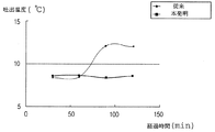
図12は、本発明により、冷媒流動部の出口側、入口側双方の冷媒分配部の、最外側の二つの分配流路を遮断した場合と、従来技術により、冷媒流動部の入口側のみの、冷媒分配部の最外側の二つの分配流路を遮断した場合との、経過時間による空気の吐出温度を比較したグラフである。 FIG. 12 shows the case where the outermost two distribution flow paths of the refrigerant distribution section on both the outlet side and the inlet side of the refrigerant flow section are blocked according to the present invention, and only the inlet side of the refrigerant flow section according to the prior art. FIG. 6 is a graph comparing air discharge temperatures according to elapsed time when the outermost two distribution channels of the refrigerant distribution section are shut off.
同図に示すように、作動初期には両者がほぼ同じ冷媒効果を示したが、時間が経過するほど従来の場合の吐出温度が上昇した。 As shown in the figure, both of them showed substantially the same refrigerant effect at the initial stage of operation, but the discharge temperature in the conventional case increased as time passed.
これによれば、冷媒流動部12(従来)の入口側冷媒分配部16(従来)の最外側の二つの分配流路16b(従来)を遮断した場合は、ある程度の冷媒流動分布効果は得られるが、まだ充分でないことがわかる。 According to this, when the outermost two
すなわち、時間が経過するほど温度が上昇する理由は、冷媒流動分布が多少不均一になってしまい、積層型熱交換器1の表面にアイシングが発生して、空気が充分に熱交換(冷却)せずに吐き出されるからである。 That is, the reason why the temperature rises as time passes is that the refrigerant flow distribution becomes somewhat non-uniform, icing occurs on the surface of the stacked
したがって、前述したように冷媒流動部112の入口側冷媒分配部116はもとより出口側冷媒分配部116の最外側の二つの分配流路も遮断すると、前記積層型熱交換器1のトップタンクタイプおよびボトムタンクタイプにおいて、すなわち積層型熱交換器の装着タイプに関係なく、冷媒が前記チューブ110、110aの冷媒流動部112内を流動するとき、慣性力または重力によって偏流が発生するのを防止して、より向上した冷媒流動分布による冷媒効率を得ることができる。 Therefore, if the outermost two distribution flow paths of the outlet side
図13は本発明に係るプレートを採用した場合と、従来の一般的なプレートを採用した場合との実験(条件:200CMH風量、ただし、CMH=m3/hour)を行い、積層型熱交換器の後方側である図7の矢印I方向からチェックした積層型熱交換器の表面温度分布を比較した図である。 FIG. 13 shows an experiment (condition: 200 CMH air volume, where CMH =
図13に示すように、従来の場合は、各チューブを流動する冷媒量が不均一となってしまい、過冷領域と過熱領域が発生し、これにより積層型熱交換器100の表面での最大温度と最小温度との差は10.4℃にもなる。 As shown in FIG. 13, in the conventional case, the amount of refrigerant flowing through each tube becomes non-uniform, and a supercooling region and a superheating region are generated, which causes the maximum on the surface of the stacked
これは、積層型熱交換器を通過する吐出空気の温度も不均一になるということを意味し、結局、搭乗者に不快感を与える。 This means that the temperature of the discharge air that passes through the stacked heat exchanger also becomes non-uniform, which ultimately gives the passenger an unpleasant feeling.
一方、本発明の場合は、各チューブ110を流動する冷媒量を均一にして冷媒の流動分布を改善することにより、積層型熱交換器の表面温度での最大温度と最小温度との差は4.2℃で、比較的一様に分布している。 On the other hand, in the case of the present invention, the difference between the maximum temperature and the minimum temperature at the surface temperature of the stacked heat exchanger is 4 by improving the flow distribution of the refrigerant by making the amount of refrigerant flowing through each
したがって、車室内に均一な温度の空気が流入することにより、搭乗者に対して快適な搭乗環境を提供し、冷媒効率をも向上させる。Therefore, when air having a uniform temperature flows into the passenger compartment, a comfortable boarding environment is provided to the passenger, and the refrigerant efficiency is improved.
前記チューブ110、110aでは、冷媒流動部112の出入口側冷媒分配部116に形成された分配流路116bのうち最外側の二つの流路を、閉鎖ビード121で遮断するか、ディンプルビードで制限して、冷媒の前記分配流路116bへの流動を図ったが、一方、前記チューブ110、110aを構成するためのプレート111を成形するとき、前記冷媒流動部112の出入口側に形成され、流路制限部125によって前記冷媒流動部の幅方向の中間部に形成された分配流路116bを有する冷媒分配部116を備えたプレート111に成形することにより、冷媒の前記中間部の分配流路116bへの流動を図ることもできる。 In the
以上説明したように、本実施例では、前記チューブ110、110aの冷媒分配部116の最外側の二つの分配流路を遮断する構成を1タンクタイプの積層型熱交換器に適用した場合について説明したが、本発明の技術的範囲はこの実施例に限定されるものでははく、前記分配流路116bを遮断する冷媒分配部116は、本発明の請求範囲内で多様な変形が可能であり、また同様の構造を2タンクタイプまたは4タンクタイプなどの熱交換器に適用しても本発明と同様の効果を得ることができる。 As described above, in the present embodiment, the case where the configuration that blocks the outermost two distribution channels of the
100 積層型熱交換器
105 入口パイプ
106 出口パイプ
110、110a チューブ
111 プレート
112 冷媒流動部
113 区画ビード
114 カップ
115、116a ビード
116 冷媒分配部
116b 分配流路
117、117a タンク
118 マニホールド
120 流路制限手段
121 閉鎖ビード
125 流路制限部
130 放熱フィン
140 エンドプレートDESCRIPTION OF
Claims (2)
前記一対のタンク(117a)の下方に延伸され、前記一対のタンク(117a)の連接部から下方に所定の長さだけ形成された区画ビード(113)により、前記一対のタンク(117a)を連結してU字型の冷媒流動部(112)が一体に形成された一対のプレート(111)と、
前記一対のプレート(111)が接合されてなり、積層された複数個のチューブ(110、110a)と、
前記チューブ(110、110a)の間に介在する多数個の放熱フィン(130)と、
前記チューブ(110、110a)に冷媒を供給又は排出するための冷媒出入口パイプ(105、106)と、
前記チューブ(110、110a)及び放熱フィン(130)を補強するためにこれらの最外側に設置される二つのエンドプレート(140)と、を含んでなる積層型熱交換器において、
前記チューブ(110、110a)の前記プレート(111)には、前記冷媒流動部(112)の出口部及び入口部に形成され、三つのビード(116a)により区画分離される四つの分配流路(116b)を有する冷媒分配部(116)が設けられ、
前記チューブ(110、110a)の内、所定のチューブ(110a)には、前記プレート(111)の一側のタンク(117a)から延設され、前記冷媒出入口パイプ(105、106)と結合されるマニホールド(118、118a)を備え、
前記マニホールド(118、118a)と結合された前記プレート(111)には、前記分配流路(116b)のうち両最外側の二つ流路が閉鎖ビード(121)で遮断されていることを特徴とする積層型熱交換器。 A pair of tanks (117a) having a cup ( 114 ) connected to the upper end,
The pair of tanks (117 a) are connected by a partition bead (113) that extends downward from the pair of tanks (117 a) and is formed by a predetermined length downward from the connecting portion of the pair of tanks (117 a). A pair of plates (111) integrally formed with a U-shaped refrigerant flow part (112),
A plurality of stacked tubes (110, 110a) formed by joining the pair of plates (111);
A plurality of heat dissipating fins (130) interposed between the tubes (110, 110a);
Refrigerant inlet / outlet pipes (105, 106) for supplying or discharging refrigerant to the tubes (110, 110a);
A laminated heat exchanger comprising two end plates (140) installed on the outermost sides of the tubes (110, 110a) and the heat dissipating fins (130);
In the plate (111) of the tube (110, 110a), there are four distribution channels (partitioned and separated by three beads (116a) formed at the outlet and inlet of the refrigerant flow part (112). 116b) is provided a refrigerant distributor (116),
Of the tubes (110, 110a), a predetermined tube (110a) extends from a tank (117a) on one side of the plate (111) and is coupled to the refrigerant inlet / outlet pipe (105, 106). A manifold (118, 118a),
Said manifold (118, 118a) and coupled to said plate (111), wherein the two channels of the two outermost of the distribution passage (116 b) is blocked in a closed bead (121) A laminated heat exchanger.
Applications Claiming Priority (2)
| Application Number | Priority Date | Filing Date | Title |
|---|---|---|---|
| KR1020020086956A KR100718262B1 (en) | 2002-12-30 | 2002-12-30 | Manifold plate for heat exchanger |
| KR1020030032832A KR100966746B1 (en) | 2003-05-23 | 2003-05-23 | Plate for evaporator |
Publications (3)
| Publication Number | Publication Date |
|---|---|
| JP2004212041A JP2004212041A (en) | 2004-07-29 |
| JP2004212041A5 JP2004212041A5 (en) | 2005-05-26 |
| JP3992237B2 true JP3992237B2 (en) | 2007-10-17 |
Family
ID=32510719
Family Applications (1)
| Application Number | Title | Priority Date | Filing Date |
|---|---|---|---|
| JP2003435926A Expired - Fee Related JP3992237B2 (en) | 2002-12-30 | 2003-12-26 | Stacked heat exchanger |
Country Status (5)
| Country | Link |
|---|---|
| US (1) | US6863120B2 (en) |
| EP (1) | EP1435502B1 (en) |
| JP (1) | JP3992237B2 (en) |
| CN (1) | CN1296672C (en) |
| DE (1) | DE60319335T2 (en) |
Cited By (1)
| Publication number | Priority date | Publication date | Assignee | Title |
|---|---|---|---|---|
| KR20210009690A (en) * | 2019-07-17 | 2021-01-27 | 한국기계연구원 | Structure for making fluid curtain on surface |
Families Citing this family (22)
| Publication number | Priority date | Publication date | Assignee | Title |
|---|---|---|---|---|
| US20060196645A1 (en) * | 2005-01-07 | 2006-09-07 | Valeo, Inc. | Heat exchanger with multilayer cladded tubes |
| KR20060102376A (en) * | 2005-03-23 | 2006-09-27 | 한라공조주식회사 | Laminated type heat exchanger |
| JP4688538B2 (en) * | 2005-03-29 | 2011-05-25 | 株式会社日本クライメイトシステムズ | Heat exchanger |
| JP4785397B2 (en) * | 2005-03-29 | 2011-10-05 | 株式会社日本クライメイトシステムズ | Vehicular air conditioner evaporator |
| TW200712421A (en) * | 2005-05-18 | 2007-04-01 | Univ Nat Central | Planar heat dissipating device |
| JP4875975B2 (en) * | 2006-01-31 | 2012-02-15 | 昭和電工株式会社 | Laminate heat exchanger |
| US7413003B2 (en) * | 2006-09-15 | 2008-08-19 | Halla Climate Control Corporation | Plate for heat exchanger |
| AU2008210471B2 (en) | 2007-01-30 | 2013-01-10 | Bradley University | A heat transfer apparatus and method |
| KR101696871B1 (en) * | 2010-09-06 | 2017-01-16 | 한온시스템 주식회사 | Water-Cooled Intercooler |
| DE202012102349U1 (en) * | 2011-07-14 | 2012-07-18 | Visteon Global Technologies, Inc. | battery cooler |
| CN103375943B (en) * | 2012-04-27 | 2015-12-09 | 珠海格力电器股份有限公司 | Evaporimeter |
| USD735842S1 (en) * | 2013-02-22 | 2015-08-04 | The Abell Foundation, Inc. | Condenser heat exchanger plate |
| USD736361S1 (en) * | 2013-02-22 | 2015-08-11 | The Abell Foundation, Inc. | Evaporator heat exchanger plate |
| WO2014155837A1 (en) * | 2013-03-29 | 2014-10-02 | 株式会社日阪製作所 | Plate-type heat exchanger |
| KR20150140836A (en) * | 2013-05-15 | 2015-12-16 | 미쓰비시덴키 가부시키가이샤 | Laminated header, heat exchanger, and air conditioner |
| CN106091784B (en) * | 2015-04-23 | 2018-05-15 | 山东大学 | A kind of heat exchange plate of Cu alloy material |
| CN104792216B (en) * | 2015-04-23 | 2016-06-29 | 山东大学 | A kind of gasket seal used in plate type heat exchanger |
| CN106091785B (en) * | 2015-04-23 | 2018-05-15 | 山东大学 | A kind of plate heat exchanger of sheet structure optimization |
| CN104848516A (en) * | 2015-06-15 | 2015-08-19 | 广州佳立空调技术有限公司 | Laminated duct piece for air conditioner and heat exchanger |
| FR3068773B1 (en) * | 2017-07-06 | 2019-09-27 | Valeo Systemes Thermiques | DEVICE FOR THERMALLY REGULATING BATTERY MODULES |
| EP3598046B1 (en) * | 2018-07-20 | 2023-05-17 | Valeo Vyminiky Tepla, s.r.o. | Heat exchanger plate and heat exchanger comprising such a heat exchanger plate |
| US11316216B2 (en) | 2018-10-24 | 2022-04-26 | Dana Canada Corporation | Modular heat exchangers for battery thermal modulation |
Family Cites Families (12)
| Publication number | Priority date | Publication date | Assignee | Title |
|---|---|---|---|---|
| US4600053A (en) * | 1984-11-23 | 1986-07-15 | Ford Motor Company | Heat exchanger structure |
| JP2536294B2 (en) * | 1987-09-03 | 1996-09-18 | 日本電装株式会社 | Stacked heat exchanger |
| JPH04177094A (en) * | 1990-11-13 | 1992-06-24 | Sanden Corp | Laminated type heat exchanger |
| US5245843A (en) * | 1991-01-31 | 1993-09-21 | Nippondenso Co., Ltd. | Evaporator |
| US6095239A (en) * | 1996-08-12 | 2000-08-01 | Calsonic Kansei Corporation | Integral-type heat exchanger |
| US5979544A (en) * | 1996-10-03 | 1999-11-09 | Zexel Corporation | Laminated heat exchanger |
| US6170565B1 (en) * | 1996-12-04 | 2001-01-09 | Zexel Corporation | Heat exchanger |
| JPH10292995A (en) * | 1997-02-21 | 1998-11-04 | Zexel Corp | Lamination-type heat exchanger |
| DE69916345T2 (en) * | 1998-01-27 | 2004-08-26 | Calsonic Kansei Corp. | Oil cooler structure |
| US5855240A (en) * | 1998-06-03 | 1999-01-05 | Ford Motor Company | Automotive heat exchanger |
| BE1012044A6 (en) | 1998-06-18 | 2000-04-04 | Solvay | Method and installation for producing an aqueous solution of hydrogen peroxide aqueous solution and hydrogen peroxide. |
| JP3911574B2 (en) * | 2000-01-08 | 2007-05-09 | 漢拏空調株式会社 | Plate for laminated heat exchanger with improved heat exchange performance and heat exchanger using the same |
-
2003
- 2003-12-24 DE DE60319335T patent/DE60319335T2/en not_active Expired - Lifetime
- 2003-12-24 EP EP03029854A patent/EP1435502B1/en not_active Expired - Fee Related
- 2003-12-26 JP JP2003435926A patent/JP3992237B2/en not_active Expired - Fee Related
- 2003-12-29 US US10/747,839 patent/US6863120B2/en not_active Expired - Lifetime
- 2003-12-30 CN CNB2003101102790A patent/CN1296672C/en not_active Expired - Fee Related
Cited By (2)
| Publication number | Priority date | Publication date | Assignee | Title |
|---|---|---|---|---|
| KR20210009690A (en) * | 2019-07-17 | 2021-01-27 | 한국기계연구원 | Structure for making fluid curtain on surface |
| KR102230206B1 (en) * | 2019-07-17 | 2021-03-22 | 한국기계연구원 | Structure for making fluid curtain on surface |
Also Published As
| Publication number | Publication date |
|---|---|
| DE60319335T2 (en) | 2009-02-19 |
| EP1435502B1 (en) | 2008-02-27 |
| US20040144524A1 (en) | 2004-07-29 |
| CN1519532A (en) | 2004-08-11 |
| JP2004212041A (en) | 2004-07-29 |
| EP1435502A2 (en) | 2004-07-07 |
| CN1296672C (en) | 2007-01-24 |
| EP1435502A3 (en) | 2004-08-25 |
| US6863120B2 (en) | 2005-03-08 |
| DE60319335D1 (en) | 2008-04-10 |
Similar Documents
| Publication | Publication Date | Title |
|---|---|---|
| JP3992237B2 (en) | Stacked heat exchanger | |
| JP2004212041A5 (en) | ||
| JP4047891B2 (en) | Heat exchanger | |
| US6431264B2 (en) | Heat exchanger with fluid-phase change | |
| JP4686062B2 (en) | Evaporator | |
| JP2004037073A (en) | Multilayer heat exchanger | |
| JPH0886591A (en) | Heat exchanger and refrigerant evaporator | |
| US7303004B2 (en) | Heat exchanger | |
| KR20060009653A (en) | Heat exchanger | |
| JP7247717B2 (en) | Heat exchanger | |
| KR101220974B1 (en) | Heat exchanger | |
| JP5508818B2 (en) | Evaporator | |
| KR101082474B1 (en) | Heat exchanger | |
| KR100718262B1 (en) | Manifold plate for heat exchanger | |
| JPH025326Y2 (en) | ||
| KR100531016B1 (en) | Heat exchanger manifold plate and heat exchanger using the same to improve refrigerant flow | |
| KR100966746B1 (en) | Plate for evaporator | |
| JP2003294338A (en) | Heat exchanger | |
| JPH0875316A (en) | Branch pipe structure for heat exchanger for air conditioner | |
| KR101134782B1 (en) | Evaporator for an Air Conditioning System of a Car | |
| KR101082469B1 (en) | Heat exchanger | |
| JPS593251Y2 (en) | Heat exchanger | |
| KR101082475B1 (en) | Heat exchanger | |
| KR20210079740A (en) | Heat exchanger | |
| JPH08285406A (en) | Laminated type heat exchanger |
Legal Events
| Date | Code | Title | Description |
|---|---|---|---|
| A621 | Written request for application examination |
Free format text: JAPANESE INTERMEDIATE CODE: A621 Effective date: 20040105 |
|
| A521 | Request for written amendment filed |
Free format text: JAPANESE INTERMEDIATE CODE: A523 Effective date: 20040213 |
|
| A521 | Request for written amendment filed |
Free format text: JAPANESE INTERMEDIATE CODE: A523 Effective date: 20040423 |
|
| A131 | Notification of reasons for refusal |
Free format text: JAPANESE INTERMEDIATE CODE: A131 Effective date: 20061003 |
|
| A521 | Request for written amendment filed |
Free format text: JAPANESE INTERMEDIATE CODE: A523 Effective date: 20070104 |
|
| A02 | Decision of refusal |
Free format text: JAPANESE INTERMEDIATE CODE: A02 Effective date: 20070130 |
|
| A521 | Request for written amendment filed |
Free format text: JAPANESE INTERMEDIATE CODE: A523 Effective date: 20070501 |
|
| A911 | Transfer to examiner for re-examination before appeal (zenchi) |
Free format text: JAPANESE INTERMEDIATE CODE: A911 Effective date: 20070606 |
|
| TRDD | Decision of grant or rejection written | ||
| A01 | Written decision to grant a patent or to grant a registration (utility model) |
Free format text: JAPANESE INTERMEDIATE CODE: A01 Effective date: 20070703 |
|
| A61 | First payment of annual fees (during grant procedure) |
Free format text: JAPANESE INTERMEDIATE CODE: A61 Effective date: 20070720 |
|
| R150 | Certificate of patent or registration of utility model |
Ref document number: 3992237 Country of ref document: JP Free format text: JAPANESE INTERMEDIATE CODE: R150 Free format text: JAPANESE INTERMEDIATE CODE: R150 |
|
| FPAY | Renewal fee payment (event date is renewal date of database) |
Free format text: PAYMENT UNTIL: 20100803 Year of fee payment: 3 |
|
| FPAY | Renewal fee payment (event date is renewal date of database) |
Free format text: PAYMENT UNTIL: 20110803 Year of fee payment: 4 |
|
| R250 | Receipt of annual fees |
Free format text: JAPANESE INTERMEDIATE CODE: R250 |
|
| FPAY | Renewal fee payment (event date is renewal date of database) |
Free format text: PAYMENT UNTIL: 20110803 Year of fee payment: 4 |
|
| FPAY | Renewal fee payment (event date is renewal date of database) |
Free format text: PAYMENT UNTIL: 20120803 Year of fee payment: 5 |
|
| R250 | Receipt of annual fees |
Free format text: JAPANESE INTERMEDIATE CODE: R250 |
|
| FPAY | Renewal fee payment (event date is renewal date of database) |
Free format text: PAYMENT UNTIL: 20130803 Year of fee payment: 6 |
|
| R250 | Receipt of annual fees |
Free format text: JAPANESE INTERMEDIATE CODE: R250 |
|
| R250 | Receipt of annual fees |
Free format text: JAPANESE INTERMEDIATE CODE: R250 |
|
| S533 | Written request for registration of change of name |
Free format text: JAPANESE INTERMEDIATE CODE: R313533 |
|
| R350 | Written notification of registration of transfer |
Free format text: JAPANESE INTERMEDIATE CODE: R350 |
|
| R250 | Receipt of annual fees |
Free format text: JAPANESE INTERMEDIATE CODE: R250 |
|
| R250 | Receipt of annual fees |
Free format text: JAPANESE INTERMEDIATE CODE: R250 |
|
| S531 | Written request for registration of change of domicile |
Free format text: JAPANESE INTERMEDIATE CODE: R313531 |
|
| S533 | Written request for registration of change of name |
Free format text: JAPANESE INTERMEDIATE CODE: R313533 |
|
| R350 | Written notification of registration of transfer |
Free format text: JAPANESE INTERMEDIATE CODE: R350 |
|
| R250 | Receipt of annual fees |
Free format text: JAPANESE INTERMEDIATE CODE: R250 |
|
| R250 | Receipt of annual fees |
Free format text: JAPANESE INTERMEDIATE CODE: R250 |
|
| R250 | Receipt of annual fees |
Free format text: JAPANESE INTERMEDIATE CODE: R250 |
|
| R250 | Receipt of annual fees |
Free format text: JAPANESE INTERMEDIATE CODE: R250 |
|
| R250 | Receipt of annual fees |
Free format text: JAPANESE INTERMEDIATE CODE: R250 |
|
| R250 | Receipt of annual fees |
Free format text: JAPANESE INTERMEDIATE CODE: R250 |
|
| LAPS | Cancellation because of no payment of annual fees |