JP3990729B2 - Apparatus for separating one or more rotationally symmetric containers from a rotationally symmetric container flow conveyed under line pressure - Google Patents
Apparatus for separating one or more rotationally symmetric containers from a rotationally symmetric container flow conveyed under line pressure Download PDFInfo
- Publication number
- JP3990729B2 JP3990729B2 JP52015197A JP52015197A JP3990729B2 JP 3990729 B2 JP3990729 B2 JP 3990729B2 JP 52015197 A JP52015197 A JP 52015197A JP 52015197 A JP52015197 A JP 52015197A JP 3990729 B2 JP3990729 B2 JP 3990729B2
- Authority
- JP
- Japan
- Prior art keywords
- conveyor
- containers
- deflecting
- slider
- separation
- Prior art date
- Legal status (The legal status is an assumption and is not a legal conclusion. Google has not performed a legal analysis and makes no representation as to the accuracy of the status listed.)
- Expired - Fee Related
Links
Images


Classifications
-
- B—PERFORMING OPERATIONS; TRANSPORTING
- B65—CONVEYING; PACKING; STORING; HANDLING THIN OR FILAMENTARY MATERIAL
- B65G—TRANSPORT OR STORAGE DEVICES, e.g. CONVEYORS FOR LOADING OR TIPPING, SHOP CONVEYOR SYSTEMS OR PNEUMATIC TUBE CONVEYORS
- B65G47/00—Article or material-handling devices associated with conveyors; Methods employing such devices
- B65G47/52—Devices for transferring articles or materials between conveyors i.e. discharging or feeding devices
- B65G47/68—Devices for transferring articles or materials between conveyors i.e. discharging or feeding devices adapted to receive articles arriving in one layer from one conveyor lane and to transfer them in individual layers to more than one conveyor lane or to one broader conveyor lane, or vice versa, e.g. combining the flows of articles conveyed by more than one conveyor
- B65G47/71—Devices for transferring articles or materials between conveyors i.e. discharging or feeding devices adapted to receive articles arriving in one layer from one conveyor lane and to transfer them in individual layers to more than one conveyor lane or to one broader conveyor lane, or vice versa, e.g. combining the flows of articles conveyed by more than one conveyor the articles being discharged or distributed to several distinct separate conveyors or to a broader conveyor lane
-
- B—PERFORMING OPERATIONS; TRANSPORTING
- B65—CONVEYING; PACKING; STORING; HANDLING THIN OR FILAMENTARY MATERIAL
- B65G—TRANSPORT OR STORAGE DEVICES, e.g. CONVEYORS FOR LOADING OR TIPPING, SHOP CONVEYOR SYSTEMS OR PNEUMATIC TUBE CONVEYORS
- B65G47/00—Article or material-handling devices associated with conveyors; Methods employing such devices
- B65G47/74—Feeding, transfer, or discharging devices of particular kinds or types
- B65G47/76—Fixed or adjustable ploughs or transverse scrapers
- B65G47/766—Adjustable ploughs or transverse scrapers
Landscapes
- Engineering & Computer Science (AREA)
- Mechanical Engineering (AREA)
- Sorting Of Articles (AREA)
- Branching, Merging, And Special Transfer Between Conveyors (AREA)
- Specific Conveyance Elements (AREA)
- Attitude Control For Articles On Conveyors (AREA)
- Food Preservation Except Freezing, Refrigeration, And Drying (AREA)
- Investigating Strength Of Materials By Application Of Mechanical Stress (AREA)
- Refuse Collection And Transfer (AREA)
- Wrapping Of Specific Fragile Articles (AREA)
- Sampling And Sample Adjustment (AREA)
- Combined Means For Separation Of Solids (AREA)
- Coating Apparatus (AREA)
- Reciprocating Pumps (AREA)
- Spinning Or Twisting Of Yarns (AREA)
- Actuator (AREA)
Abstract
Description
本発明は、1個または複数個の回転対称性を有する容器をラインプレッシャーを受けながら搬送される回転対称性を有する容器の流れから分離するための装置に関するものである。この装置は、容器の流れに対する第1コンベアと分離された容器を取り除くための第2コンベヤとからなり、第2コンベヤは分離点において第1コンベヤから分岐している。この装置はさらに、第1コンベヤから第2コンベヤへ分離されるべき容器を搬送するための装置を有している。容器はラインプレッシャーを受けながら搬送されているので、容器を第1コンベヤ上に保持するガイドレールが第1コンベヤの左右に配置されている。
ラインプレッシャーを受けながら搬送される容器の流れから個々の容器を分離することは、これまでは専ら星型ホイールによってなされてきた。
ラインプレッシャーを受けることなく搬送され、したがって、互いに間隔を開けて搬送される容器を分離するための多くの装置が知られており、例えば、EP−A−0 003 111においては、各部分からなる分岐排出装置および逸らせガスノズルが知られている。しかしながら、前記装置はラインプレッシャーを受けながら搬送される容器を分離するのには適していない。
本発明の目的は、可能な最も単純な構成を有し、信頼性をもって作動する装置を用いることにより、ラインプレッシャーを受けながら搬送されるこのような容器の流れから個々の容器を分離することができるようにし、第1コンベヤ、例えばコンベヤベルトまたはリンクチェインコンベヤ上に容器の流れを留めておくことができるようにすることにある。
前記目的は、本発明に従って第1コンベヤが分離点において一方の側に向かって鋭角をなして曲がり、第2コンベヤが分離点において第1コンベヤから他方の側に向かって鋭角をなして分岐し、第1および第2コンベヤの間に分離楔が形成され、第1逸らせスライダが容器の運動経路の外側に配置される引っ込んだ位置と第2コンベヤの分岐点側において分離点の始端から分離楔の先端に向かってのびる突出した位置の2つの位置の間において運動可能に配置され、第2の逸らせスライダが容器の運動経路の外側に配置される引っ込んだ位置と、第1コンベヤの曲がる側において分離点の始端から第1コンベヤの少なくとも略1/2の幅に渡って分離楔の先端の方向に沿ってのびる突出した位置の2つの位置の間において運動可能に配置されるような構成とすることによって解決される。
第1逸らせスライダがその突出した位置にあり、また第2逸らせスライダがその引っ込んだ位置にあるとき、容器は第1の曲がったコンベヤ上を搬送されている。分離されるべき容器が分離点に達すると、それが、例えば底に配置されたトリガーリミッタによって検出され、第1逸らせスライダは引っ込み、第2逸らせスライダがのび、その結果、分離されるべき容器は、後続の容器により、分岐する第2コンベヤ上に押し出される。その後、第1逸らせスライダは分離されるべき容器のすぐ後ろにおいて再びのび、それと同時に第2逸らせスライダは引っ込み、それによって後続の容器は再び第1コンベヤ上を搬送される。
1個またはそれ以上の容器が容器の流れから分離されるとき、生じた間隔は存在するラインプレッシャーのためにすぐに閉じられる。間隔が閉じることによって、短時間の強い加速と圧力変動が生じ、これらは搬送方向に沿って、または搬送方向と反対方向に沿って伝播する。容器の急激な動きによって、個々の対象物の電子工学的追跡の際にエラーが生じることを防止するため、この圧力変動を減衰させるための装置を備えることが賢明である。このような装置は、第1コンベヤ上において分離点に向かって配置され、その上を容器がスライドする薄いプレートから形成され得る。
本発明による装置は清涼飲料充填装置の一部を形成し得る。かかる清涼飲料充填装置は、清涼飲料用ボトルが欠陥を有しておらず、清潔でかつ異物を有していないことを検査するステーションを備えている。ラインプレッシャー下に底および側壁を検査するための装置が、同時に出願されたPCT国際出願「容器の底を検出するための装置を通過させて容器を搬送するための方法および装置」(我々のケースナンバー:30562/底検査)および「ボトルのような回転対称性を有する容器をそれらがラインプレッシャーを受けて搬送される間に回転せしめるための方法および装置」(我々のケースナンバー:30560/自動回転)に記載されている。底の検査および側壁の検査、並びに本発明に基づく、欠陥があるものと判定された個々の容器の分離が、ラインプレッシャー下に実行されることによって、装置の全体構成が実質上単純化される。なぜならば、通常配置される充填装置は取り入れ領域においてラインプレッシャーを必要とするからである。したがって、容器を離れ離れに配置することによって、それらが底および側壁検査のための装置の上流側において相互に間隔を開けて配置されるようにし、あるいはその後再びラインプレッシャーを生じさせる必要はない。
底の検査または側壁の検査の結果を個々の容器に割り当てることは、FIFOシフトレジスタによって実行され、このレジスタの内容は、その都度容器が分離点のすぐ上流に配置された光リミッタに達するまで、第1コンベヤ上における容器のさらなる運動に対応して漸次計時される。第1コンベヤ上における容器のさらなる運動は、容器の流れに作用する星型ホイール、CCDラインスキャンカメラ、フォトダイオードアレイまたはドップラー効果を用いた通過速度測定器またはそれらに類するものを用いることによって決定され得る。検査結果を個々の容器に割り当てる前記方法は、物品が互いに間隔をあけて搬送されるような装置から既に知られていることである。
好ましくは、分離楔は縦方向に2つに分割されており、これら2つの部分は、その都度、それぞれ第1および第2逸らせスライダに沿って、その外側エッジの方向に沿って運動し得るようになっている。分離楔の各部分および逸らせスライダは、第1コンベヤまたは第2コンベヤの略中間において出会う。それによって、容器のより正確な分離およびより高い容器の処理効率が達成される。
より高い容器処理効率を達成する際の分離装置の動作は、逸らせスライダのすぐ上流側に、第1コンベヤのガイドレールにおいて旋回可能なフラップを設けることによって可能になる。この旋回フラップは、既に個々の容器に対し、第1コンベヤの曲がり部分の方向に、あるいは分岐する第2コンベヤの方向に運動量を及ぼし、それによって、容器が第1または第2逸らせスライダと出くわすときに方向の変化があまり急激に生じない。
分離を改善するためのさらなる可能性は、分離楔をその広がった下流側端において旋回可能に支持することである。その結果、分離楔の先端は旋回することができ、そして、個々の容器の運動方向の変化はより小さなものとなる。
2つの逸らせスライダは空気圧シリンダによってのばされる。それらの伸びの速度はほぼ容器の通過速度に一致している。したがって、空気圧ピストンの膨張速度を制御可能とすることが目的に適っている。これは、好ましくは、2重作動ピストンを用いることによってなされる。ピストンの膨張時にピストン前方のチャンバから生じる空気の流れは、調節可能なスロットルによって制御可能である。ピストンの膨張および収縮速度は、シリンダの全長にわたって分布しかつバルブによってその都度制御される複数個の通気孔を備えることによって制御される。ピストンが一端において圧縮空気の作用を受けるとき、ピストンの他端において通気孔は順次開口され、ピストンは、その都度、開口した通気孔に至るまで段階的に運動する。前記手段によってピストンの移動距離および移動速度が制御され得る。このようなシリンダはまた、膨張速度または膨張距離が変化し得るような他のアプリケーションに対して適用され得る。
以下において、図面を参照しながら本発明の実施例を説明する。
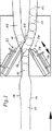
図1は、2つの逸らせスライダを備えた本発明による装置の1実施例を示す図である。
図2は、2つの逸らせスライダ、および縦方向に分割され、その各部分が運動可能とされた付加的な分離楔を備えた本発明による装置の1実施例を示した図である。
図3は、2つの逸らせスライダと付加的な2つの逸らせフラップを備えた本発明による装置の1実施例を示した図である。
図4は、2つの逸らせスライダと付加的な旋回分割楔を備えた本発明による装置の1実施例を示した図である。
図5は、容器の搬送速度を決定するために第1コンベヤに隣接して配置された星型ホイールの平面図である。
図6は、容器の搬送速度を決定するためのラインスキャンカメラ並びに圧力を減衰させる装置に結合された本発明による装置を示した図である。
図7は、搬送方向に対して直角な断面において容器の搬送速度を決定するためのラインスキャンカメラを示した図である。
図8は、次第に膨張し得るピストンを備えたシリンダの概略図である。
図9は、ピストンの膨張速度が制御可能なシリンダの概略図である。
図1によれば、空ボトル10が第1コンベヤ12上をラインプレッシャーを受けながら搬送される。第1コンベヤは例えば、コンベヤベルトまたはリンクチェインコンベヤから形成される。空ボトル10は第1コンベヤ12上をガイドレール14によって案内される。2つのガイドレール14間の間隔は空ボトル10の直径より1〜10mm大きくなっている。分離点16において第1コンベヤ12は約30°の角度をなして一方の側に向かって、すなわち図1では右側に向かって曲がっており、そして、第2コンベヤ18は約30°の角度をなして他方の側に向かって、すなわち図1では左側に向かって分岐している。それによって分離楔20が両方のコンベヤ12および18の間に形成されている。
実際、このような構成は、空ボトル10の直径の約3または4倍の大きさの幅を備えたコンベヤベルトまたはリンクチエインコンベヤを用いることによって実現され得る。空ボトル10はガイドレール14によってリンクチェインコンベヤ上を案内される。曲げられる場合、リンクチェインコンベヤは直線的にのび、ガイドレール14のみが曲げられる。したがって、空ボトル10は、リンクチェインコンベヤの運動方向に対してわずかに斜めに曲げられた領域において搬送される。同様に、分岐する第2コンベヤ18上の空ボトルは、ガイドレール14によってリンクチェインコンベヤ上を斜めに運動せしめられる。好都合なことに3本の平行に走るリンクチェインコンベアは、分離点で重なり合っており、空ボトル10は、中間のリンクチェインコンベヤ上を搬送され、そして、曲がるガイドレール14によって、右側に並んで走るリンクチェインコンベヤ上に移動する。一方、空ボトル10は、反対側の方向に分岐するガイドレールによって左側に並んで走るリンクチェインコンベヤ上に移動する。容器を、2本のリンクチェインコンベヤ上に同心に配置された分離点16まで案内し、そしてそこで、本発明による装置を用いて、2本のコンベヤ12および18のうちの一方に移動させることができる。第2コンベヤ18は直線状のコンベヤから形成されている必要はなく、また、回転テーブルから形成され得る。
分離点16において、すなわち2本のコンベヤ12および18の曲がりの開始点において、第1逸らせスライダ22および第2逸らせスライダ24が、第1コンベヤ12の両側に配置されている。2つの逸らせスライダ22、24は、それぞれ先端に向かって先細に形成され、空気圧シリンダ28によってのび、または引っ込むことができるように支持されたロッド26からなっている。第1逸らせスライダ22は、近接する第1コンベア12の側に配置され、その下流側において第2コンベヤ18が分岐している。また、第2逸らせスライダ24は、近接する第1コンベヤ12の側に配置され、その下流側において第1コンベヤ12が曲がっている。逸らせスライダ22、24は、引っ込んだ位置において、第1および第2コンベヤ12、18の外側に配置されている。2つの逸らせスライダ22、24は分離楔20に向かってのびることができ、その突出した位置において、それぞれ第2および第1コンベヤ18、12の幅の少なくとも半分の距離までのびる。特に、第2逸らせスライダ24は、第1コンベヤの幅のほぼ中間までのび得ることで十分である。第1逸らせスライダ22は、その突出した位置において、第2コンベヤ18の分岐によって生じたガイドレール14の間隙を埋め、それによって、空ボトル10はすべて、第1コンベヤ12上を搬送され続ける。分離されるべき欠陥のある空ボトル11が分離点16に達したとき、第2逸らせスライダ24は先行する最後尾の不良品でないボトルのすぐ後ろにのび、それによって欠陥のある空ボトル11は第1コンベヤ12上に沿って動くことを妨げられる。同時に、第1逸らせスライダ22は引っ込み、その結果、分離されるべき空ボトル11が後続の空ボトル10によって生じるラインプレッシャーによって第2コンベヤ上に押し出される。もし次の空ボトルが同様に分離さけなければならないなら、第1逸らせスライダ22はその引っ込んだ位置に留まり、第2逸らせスライダ24はその突出した位置に留まっている。他方、もし次の空ボトルが不良品でなく、第1コンベヤ12上をさらに搬送されなければならなないなら、第1逸らせスライダ22は再び分離された空ボトル11のすぐ後ろにのび、第2逸らせスライダ24は引っ込み、それによって第1コンベヤ12上に再び経路が開けられる。
図2に示した実施例によれば、固定された分離楔20の代わりに2つの運動し得る先の尖った部材30、32からなる分割楔20が用いられる。これら先の尖った部材30、32は、それぞれ、空気圧シリンダ34、36によって、第1および第2逸らせスライダ22、24に向かって運動することができ、それによって逸らせスライダ22、24がのびる距離を短縮する。先の尖った部材30、32は、それぞれ、第1および第2コンベヤ12、18の中間まで運動することができ、その結果、逸らせスライダ22、24の運動距離は半分になる。したがって、運動に要する時間が短縮され、その結果、より高いボトル処理率が可能となる。
図3の実施例によれば、第1および第2逸らせフラップ38、40が分離点16のすぐ上流側において、または当該分離点16において、第1コンベヤ12と並んで横に配置されている。逸らせフラップ38、40はその後端において旋回可能に支持されており、それらの搬送方向に向けられた先端は、空気圧シリンダ42、44によって旋回軸のまわりに旋回することができる。逸らせスライダ22、24がのびる直前に、またはそれと同時に、第1コンベヤ12と同一の側において直後に配置された逸らせフラップ38または40が、関係するシリンダ42または44によって制御され、次のボトルに逸らせスライダ22、24の先端から離れるような運動量を及ぼし、のびる逸らせスライダ22、24に対する空間を作り出す。したがって、逸らせスライダ22、24ののびる時期に対する大きな時間的な窓が存在する。例えば、分離されるべき容器11は、すでに第2逸らせフラップ40によって第2コンベヤ18の方向に沿って運動量を与えられているので、第2逸らせスライダ24は、空ボトル10に出くわす危険を生じることなく、相対的に遅れてのびることができる。
図4の実施例によれば、分割された楔20はその広がった端部において支持され、軸46のまわりに旋回可能になっている。この旋回は、空気圧シリンダ48によってなされる。空ボトルが第2コンベヤ18上に逸らされない場合には、分割された楔20は第2コンベヤ18に向かってわずかに旋回する位置に配置され、その結果、空ボトル10は第1コンベヤ12上を分割された楔20を通過して搬送され続ける。分離されるべき空ボトル11が分離点16に達したとき、分割された楔20は第2コンベヤ18から逸れ、第1コンベヤ12に向かって旋回せしめられる。これによって第2逸らせスライダ24に対する伸びの距離はやや短くなる。これは空ボトルの処理効率を向上させる別の可能な方法である。
2つの逸らせスライダ22、24の伸びの速度は空ボトル10の速度にほぼ一致しており、よって、逸らせスライダ22、24の先端は、それがのびるとき、いわば、空ボトル10とともにさらに運動し、これらの間にスライドする。空ボトルがラインプレッシャーを受けながら搬送されるとき、空ボトル10の速度は急激に変化し、第1コンベヤ12が駆動される速度以下となるので、空ボトル10が運動する速度を把捉することが好都合である。この目的のため、図5によれば、星型ホイール50が分離点16の上流において第1コンベヤ12に隣接して配置される。星型ホイールは、その歯を空ボトル10の間に係合させており、それを通過する空ボトル10によって駆動される。そのとき、星型ホイール50の回転速度から空ボトル10の速度を決定し、それに従って第1および第2逸らせスライダ22、24ののびる速度を制御することができる。同時に、星型ホイール50の回転から、FIFOシフトレジスタにおける底または側壁検査の結果のさらなる計時に対するクロックパルスを導出することができ、その結果、もし、特定の空ボトルが分離点16の直前に配置された光リミッタを通過するならば、その都度、特定の空ボトルに関係し、測定結果を含む制御信号が存在し、それによって、空ボトル10が底または側壁検査の間に欠陥を有すると判定される場合には、分離過程が開始される。
ボトルの搬送速度を測定する別の可能性は、星型ホイールの代わりにラインスキャンカメラ101を用いることである。ラインスキャンカメラ101は、搬送装置の搬送面における光源100の反対側の位置であって、ボトルの口の高さレベルに配置されている。搬送速度は、マイクロプロセッサ回路を用いて、カメラの一連のシグナルから計算される(図6および7参照)。容器の流れは、揺らぐ圧力条件に基づいて容器の分離がなされる場合には、急激に加速され得る。場合によっては、不正確な測定が生ずる可能性がある。この挙動は、もし、ラインスキャンカメラと分離点との間の領域において、減衰エレメントとして容器の流れに対するわずかな機械的抵抗を設けることによって相殺することができる。減衰エレメントは例えば、コンベヤ上に配置され、その上を容器が滑走する薄いプレート102によって実現され得る(図6参照)。
図8はその全長にわたって分布する複数個の通気孔0、1、2、…、nを備えた空気圧シリンダ60の概略図である。各通気孔は独立した制御バルブ62に接続されている。ピストンロッド66を備えたピストン64は、シリンダ60内において運動可能になっている。図8のピストン64がその左端位置からその右端位置まで動かされるとき、通気孔0はその制御バルブ62によって圧縮空気源に接続され、一方、それ以外の通気孔の制御バルブ62は閉じられている。そのとき、ピストン64は、空気がピストンロッド端において逃げられないので、運動することができない。その後、通気孔1が制御バルブ62を通じて通気され、よって、ピストン64は、それが通気孔1の開口を閉じるまで右側に運動する。通気孔1に対する制御バルブ62はその後閉じられ得る。ピストンはすでに通気孔1の開口を閉じているので、制御バルブ62の制御は時間的に決定される。次の通気孔2、3、4、…、nが開かれることによってピストン64は次第に右側に動かされ得る。通気孔0を閉じ、通気孔nを圧縮空気に接続することによってピストン64は逆の順序でバルブn−1〜1の時系列的な通気によって次第に左側に動かされる。したがって、ピストン64は中間位置に保持されることができるということは明らかである。ピストンの速度を制御するための別の可能な方法が図9に示してある。図9において、ピストンロッド76を備えたピストン74は、シリンダ70の内部で運動する。シリンダの左端は、制御バルブ72を通じて圧縮空気源に接続されることができ、一方、シリンダ70の右端は一連の制御可能なスロットルチェックバルブ78を通じて、汚れた空気側において減圧される。スロットルチェックバルブ78は、それぞれ、制御バルブ80およびバイパスラインによって橋渡しされ得る。ピストンロッドが最大速度でのびるとき、空気は、最も少なく絞られたバルブを通じて排出される。膨張速度は、汚れた空気中に接続された強く絞られたバルブ78によって、減速され得る。切り換えられ得る複数個のスロットルチェックバルブ78の代わりに、アクチュエータによって調節される単一のスロットルバルブを用いることが可能である。前記調節はステッピングモータによってなされる。
前述したシリンダ60、70は特に逸らせシリンダ22、24の伸びの速度を制御するのに適している。伸びの距離はシリンダ60によって調節され得る。このようなシリンダはまた、分離装置の逸らせシリンダ22、24を駆動する以外の目的のためにも用いるられ得る。
図8および9に示したシリンダによって、まず最初、逸らせシリンダ22、24が、増大した速度でのばされ、その後、逸らせスライダ22、24の先端がコンベヤベルトの中間に接近し、逸らせスライダ22、24の先端が多かれ少なかれ半径方向に容器10に出くわすおそれがあり、場合によっては容器10を壊すおそれがある場合、伸びの速度を容器10の搬送速度まで減少させることが可能である。The present invention relates to an apparatus for separating one or a plurality of rotationally symmetric containers from a rotationally symmetric container flow conveyed under line pressure. The apparatus consists of a first conveyor for container flow and a second conveyor for removing separated containers, the second conveyor branching from the first conveyor at the separation point. The apparatus further comprises an apparatus for transporting containers to be separated from the first conveyor to the second conveyor. Since the containers are conveyed while receiving line pressure, guide rails for holding the containers on the first conveyor are arranged on the left and right sides of the first conveyor.
The separation of individual containers from the flow of containers conveyed under line pressure has heretofore been done exclusively by star wheels.
Many devices are known for separating containers which are transported without being subjected to line pressure and are therefore transported at a distance from one another, for example in EP-A-0 003 111 consisting of parts. Branch discharge devices and diverting gas nozzles are known. However, the apparatus is not suitable for separating containers transported under line pressure.
It is an object of the present invention to separate individual containers from such a container stream being conveyed under line pressure by using a device that has the simplest possible configuration and operates reliably. It is possible to keep the flow of containers on a first conveyor, for example a conveyor belt or a link chain conveyor.
The object is that according to the invention the first conveyor bends at an acute angle towards one side at the separation point, and the second conveyor branches at an acute angle from the first conveyor towards the other side at the separation point, A separation wedge is formed between the first and second conveyors, and the separation wedge is separated from the beginning of the separation point at the retracted position where the first deflecting slider is disposed outside the movement path of the container and the branch point side of the second conveyor A retracted position in which the second deflecting slider is disposed outside the movement path of the container, and a bending side of the first conveyor. In a movable manner between the two positions of the protruding position extending along the direction of the leading edge of the separating wedge from the starting end of the separating point over the width of at least approximately half of the first conveyor. It is solved by a structure such as.
When the first deflecting slider is in its extended position and the second deflecting slider is in its retracted position, the containers are being transported on the first bent conveyor. When the container to be separated reaches the separation point, it is detected, for example, by a trigger limiter located at the bottom, the first deflection slider retracts and the second deflection slider extends, so that it should be separated Containers are pushed onto the branching second conveyor by subsequent containers. Thereafter, the first deflector slider extends again immediately behind the containers to be separated, while at the same time the second deflector slider is retracted, whereby the subsequent containers are transported again on the first conveyor.
When one or more containers are separated from the container stream, the resulting spacing is immediately closed due to the existing line pressure. Closing the interval causes a short period of strong acceleration and pressure fluctuations that propagate along the transport direction or along the opposite direction of the transport direction. In order to prevent the sudden movement of the container from causing errors in the electronic tracking of individual objects, it is advisable to have a device for attenuating this pressure fluctuation. Such a device can be formed from a thin plate that is placed on the first conveyor towards the separation point, on which the container slides.
The device according to the invention may form part of a soft drink filling device. Such a soft drink filling device is provided with a station for inspecting that a soft drink bottle has no defects, is clean, and has no foreign matter. An apparatus for inspecting the bottom and side walls under line pressure was filed at the same time as the PCT international application “Method and apparatus for transporting containers through a device for detecting the bottom of a container” (our case) Number: 30562 / bottom inspection) and "Method and apparatus for rotating bottle-like containers with rotational symmetry while they are conveyed under line pressure" (our case number: 30560 / automatic rotation) )It is described in. The overall configuration of the apparatus is substantially simplified by performing bottom and side wall inspections and separation of individual containers determined to be defective according to the present invention under line pressure. . This is because normally placed filling devices require line pressure in the intake area. Thus, it is not necessary to place the containers remotely so that they are spaced apart from each other upstream of the apparatus for bottom and side wall inspection, or to create line pressure again thereafter.
Assigning the results of bottom inspection or side wall inspection to individual containers is performed by a FIFO shift register until the contents of the register reach an optical limiter located just upstream of the separation point each time. Incrementally timed in response to further movement of the containers on the first conveyor. The further movement of the containers on the first conveyor is determined by using a star wheel acting on the container flow, a CCD line scan camera, a photodiode array or a pass velocity measuring device using the Doppler effect or the like. obtain. Said method of assigning test results to individual containers is already known from devices in which articles are transported at intervals.
Preferably, the separating wedge is divided in two longitudinally, the two parts being able to move along the direction of its outer edge, respectively, along the first and second deflection sliders, respectively. It is like that. Each part of the separating wedge and the deflection slider meet approximately in the middle of the first conveyor or the second conveyor. Thereby, more accurate separation of the containers and higher container processing efficiency is achieved.
Operation of the separating device in achieving higher container handling efficiency is made possible by providing a pivotable flap in the guide rail of the first conveyor just upstream of the deflecting slider. This swivel flap already exerts momentum on the individual containers in the direction of the bent portion of the first conveyor or in the direction of the second conveyor which branches off, so that the containers encounter the first or second deflecting slider. Sometimes the change of direction does not occur very rapidly.
A further possibility for improving the separation is to pivotably support the separation wedge at its widened downstream end. As a result, the tip of the separating wedge can be swiveled and the change in the direction of movement of the individual containers is smaller.
The two deflection sliders are extended by a pneumatic cylinder. Their rate of elongation is approximately in line with the speed of passage of the container. Therefore, it is suitable for the purpose to control the expansion speed of the pneumatic piston. This is preferably done by using a double acting piston. The air flow arising from the chamber in front of the piston during expansion of the piston can be controlled by an adjustable throttle. The expansion and contraction speed of the piston is controlled by providing a plurality of vents distributed over the entire length of the cylinder and controlled each time by a valve. When the piston is subjected to the action of compressed air at one end, the vent holes are sequentially opened at the other end of the piston, and the piston moves step by step until reaching the open vent hole each time. The moving distance and moving speed of the piston can be controlled by the means. Such cylinders can also be applied to other applications where the expansion rate or expansion distance can vary.
Embodiments of the present invention will be described below with reference to the drawings.
FIG. 1 shows an embodiment of the device according to the invention with two deflection sliders.
FIG. 2 shows an embodiment of the device according to the invention with two deflecting sliders and an additional separating wedge divided in the longitudinal direction, each part being movable.
FIG. 3 shows an embodiment of the device according to the invention with two deflection sliders and two additional deflection flaps.
FIG. 4 shows an embodiment of the device according to the invention with two deflection sliders and an additional pivoting wedge.
FIG. 5 is a plan view of a star wheel located adjacent to the first conveyor to determine the container transport speed.
FIG. 6 shows a device according to the invention coupled to a line scan camera for determining the transport speed of a container and a device for damping pressure.
FIG. 7 is a diagram showing a line scan camera for determining the container conveyance speed in a cross section perpendicular to the conveyance direction.
FIG. 8 is a schematic view of a cylinder with a piston that can gradually expand.
FIG. 9 is a schematic view of a cylinder in which the expansion speed of the piston can be controlled.
According to FIG. 1, the
In fact, such a configuration can be realized by using a conveyor belt or link chain conveyor with a width about 3 or 4 times the diameter of the
At the
According to the embodiment shown in FIG. 2, instead of a fixed separating
According to the embodiment of FIG. 3, the first and second deflecting flaps 38, 40 are arranged side by side with the
According to the embodiment of FIG. 4, the
The speed of extension of the two deflecting
Another possibility to measure bottle transport speed is to use a
FIG. 8 is a schematic view of a pneumatic cylinder 60 having a plurality of
The
8 and 9, the
Claims (8)
容器の流れを生じさせ、容器の分離点において鋭角をなして曲がっている第1コンベヤと、
分離された容器を除去するように機能し、前記分離点において前記第1コンベヤから分岐して配置された第2コンベヤと、
前記第1及び第2コンベヤの間に配置された分離楔と、
前記第1コンベヤの搬送路上における前記分離点の上流側において容器の速度を測定する速度測定手段と、
前記分離点において前記第2コンベヤの分岐する側に前記第1コンベヤに隣接して配置され、容器の搬送経路の外側に位置する引っ込んだ位置と、前記分離楔の先端に向かってのびる突出した位置の2つの位置の間において運動可能な第1逸らせスライダと、
前記分離点において前記第1コンベヤの曲がる側に前記第1コンベヤに隣接して配置され、容器の搬送経路の外側に位置する引っ込んだ位置と、前記分離楔の先端に向かってのびる突出した位置の2つの位置の間において運動可能な第2逸らせスライダと、を備え、
前記第1逸らせスライダが前記突出した位置をとるとともに、前記第2逸らせスライダが前記引っ込んだ位置をとるとき、容器は前記第1コンベヤ上を搬送され続け、前記第1逸らせスライダが前記引っ込んだ位置をとるとともに、前記第2逸らせスライダが前記突出した位置をとることによって、容器が前記第2コンベヤ上に分離されるようになっており、
前記第1および第2逸らせスライダの運動速度が、前記速度測定手段による測定結果に従って制御されることを特徴とする装置。An apparatus for separating individual rotationally symmetric containers from the flow of rotationally symmetric containers conveyed under line pressure,
A first conveyor that creates a flow of containers and is bent at an acute angle at a separation point of the containers;
A second conveyor that functions to remove the separated containers and is branched from the first conveyor at the separation point;
A separation wedge disposed between the first and second conveyors;
Speed measuring means for measuring the speed of the container on the upstream side of the separation point on the conveying path of the first conveyor;
A retracted position that is disposed adjacent to the first conveyor on the branching side of the second conveyor at the separation point and is positioned outside the container conveyance path, and a protruding position that extends toward the tip of the separation wedge A first deflection slider movable between the two positions;
At the separation point, on the bent side of the first conveyor, adjacent to the first conveyor, a retracted position positioned outside the container transport path and a protruding position extending toward the tip of the separation wedge A second deflecting slider movable between the two positions,
When the first deflecting slider assumes the protruding position and the second deflecting slider assumes the retracted position, the containers continue to be transported on the first conveyor, and the first deflecting slider is Taking the retracted position and taking the projecting position of the second deflecting slider, the containers are separated on the second conveyor,
The apparatus is characterized in that movement speeds of the first and second deflecting sliders are controlled according to a measurement result by the speed measuring means.
Applications Claiming Priority (3)
| Application Number | Priority Date | Filing Date | Title |
|---|---|---|---|
| DE29518636U DE29518636U1 (en) | 1995-11-24 | 1995-11-24 | Device for discharging individual rotationally symmetrical containers from a stream of rotationally symmetrical containers and cylinders conveyed under dynamic pressure with a piston which can be extended in a controlled manner |
| DE29518636.4 | 1995-11-24 | ||
| PCT/EP1996/005191 WO1997019873A1 (en) | 1995-11-24 | 1996-11-25 | Device for selecting one or more rotationally symmetrical containers from a stream of rotationally symmetrical containers conveyed under pressure from behind, and cylinder with controlled plunger |
Publications (2)
| Publication Number | Publication Date |
|---|---|
| JPH10513427A JPH10513427A (en) | 1998-12-22 |
| JP3990729B2 true JP3990729B2 (en) | 2007-10-17 |
Family
ID=8015855
Family Applications (1)
| Application Number | Title | Priority Date | Filing Date |
|---|---|---|---|
| JP52015197A Expired - Fee Related JP3990729B2 (en) | 1995-11-24 | 1996-11-25 | Apparatus for separating one or more rotationally symmetric containers from a rotationally symmetric container flow conveyed under line pressure |
Country Status (14)
| Country | Link |
|---|---|
| EP (1) | EP0805771B1 (en) |
| JP (1) | JP3990729B2 (en) |
| AT (1) | ATE215902T1 (en) |
| BR (1) | BR9606786A (en) |
| CA (1) | CA2206494C (en) |
| DE (2) | DE29518636U1 (en) |
| DK (1) | DK0805771T3 (en) |
| EA (1) | EA000143B1 (en) |
| ES (1) | ES2175150T3 (en) |
| HU (1) | HU223064B1 (en) |
| MX (1) | MX9705470A (en) |
| PL (1) | PL181924B1 (en) |
| WO (1) | WO1997019873A1 (en) |
| ZA (1) | ZA969873B (en) |
Cited By (1)
| Publication number | Priority date | Publication date | Assignee | Title |
|---|---|---|---|---|
| KR102120586B1 (en) * | 2019-04-15 | 2020-06-16 | 박준희 | Bottle branching system for preventing bottle drop and breakage |
Families Citing this family (9)
| Publication number | Priority date | Publication date | Assignee | Title |
|---|---|---|---|---|
| DE102009003475A1 (en) * | 2009-02-12 | 2010-08-19 | Krones Ag | Conveyor and method for feeding a further processing unit |
| ITBO20110552A1 (en) * | 2011-09-27 | 2013-03-28 | Ima Life Srl | DEVICE AND METHOD FOR TAKING AND ENTERING CONTAINERS FROM AND ON A CONVEYANCE LINE |
| CN106829417B (en) * | 2015-12-04 | 2020-01-03 | 楚天科技股份有限公司 | High-speed feeding and discharging system |
| DE102017214526A1 (en) * | 2017-08-21 | 2019-02-21 | Putzmeister Engineering Gmbh | Fluid driven actuator cylinder with an intermediate position and method for actuating such actuator cylinder |
| FR3086574B1 (en) * | 2018-09-27 | 2020-09-04 | Sidel Participations | HOLLOW BODY MANUFACTURING PLANT INCLUDING A HOLLOW BODY CIRCULATION REGULATOR MOVED BY A LINEAR ELECTRIC MOTOR |
| CN109573532A (en) * | 2019-01-08 | 2019-04-05 | 泉州市微柏工业机器人研究院有限公司 | A kind of round table-like part material sorting device and feeding device |
| CN111824826B (en) * | 2020-07-23 | 2022-11-04 | 合肥市贵谦信息科技有限公司 | Conveying system of home textile fabric |
| CN112707154B (en) * | 2020-12-16 | 2022-12-13 | 赖宝建 | Cargo retention prevention conveyor and cargo conveying method |
| CN117963500B (en) * | 2024-03-29 | 2024-06-25 | 山东硕晟机械制造有限公司 | Automatic feeding device for conveyor |
Family Cites Families (9)
| Publication number | Priority date | Publication date | Assignee | Title |
|---|---|---|---|---|
| US2515871A (en) * | 1948-09-16 | 1950-07-18 | William H Hartmann | Automatic dividing device for conveyer systems |
| US2999001A (en) * | 1959-10-22 | 1961-09-05 | Pannier Corp | Fluid actuated servo index |
| DE1217865B (en) * | 1963-03-02 | 1966-05-26 | Ind G M B H | Switchable pipe branching |
| US3351198A (en) * | 1965-02-25 | 1967-11-07 | Owens Illinois Inc | Glass container sorting |
| US3355002A (en) * | 1965-10-11 | 1967-11-28 | American Flange & Mfg | Method and apparatus for dividing the flow of articles |
| DE2211124A1 (en) * | 1972-03-08 | 1973-09-13 | Bauer Eberhard | SWITCH FOR DISTRIBUTION OF LONGITUDINAL PIECES OF GOODS ON TWO CONVEYOR TRACKS |
| NL183024C (en) * | 1977-06-22 | 1988-07-01 | Stork Bepak Bv | Apparatus for diverting objects moving from one supply path to different outlets. |
| DE2801387A1 (en) * | 1978-01-13 | 1979-07-19 | Bernhard Heuft | SORTING MACHINE |
| DE4132811A1 (en) * | 1991-10-02 | 1993-04-08 | Conto Control Herbert Heiden | Bottle processing machine with distributor - has two individually movable sliders moving jointly against deflection direction |
-
1995
- 1995-11-24 DE DE29518636U patent/DE29518636U1/en not_active Expired - Lifetime
-
1996
- 1996-11-25 ES ES96939917T patent/ES2175150T3/en not_active Expired - Lifetime
- 1996-11-25 DK DK96939917T patent/DK0805771T3/en active
- 1996-11-25 PL PL96321455A patent/PL181924B1/en unknown
- 1996-11-25 BR BR9606786A patent/BR9606786A/en not_active IP Right Cessation
- 1996-11-25 CA CA002206494A patent/CA2206494C/en not_active Expired - Lifetime
- 1996-11-25 EP EP96939917A patent/EP0805771B1/en not_active Expired - Lifetime
- 1996-11-25 WO PCT/EP1996/005191 patent/WO1997019873A1/en active IP Right Grant
- 1996-11-25 EA EA199700131A patent/EA000143B1/en not_active IP Right Cessation
- 1996-11-25 ZA ZA9609873A patent/ZA969873B/en unknown
- 1996-11-25 AT AT96939917T patent/ATE215902T1/en active
- 1996-11-25 JP JP52015197A patent/JP3990729B2/en not_active Expired - Fee Related
- 1996-11-25 DE DE59609061T patent/DE59609061D1/en not_active Expired - Lifetime
- 1996-11-25 HU HU9701880A patent/HU223064B1/en active IP Right Grant
-
1997
- 1997-07-18 MX MX9705470A patent/MX9705470A/en unknown
Cited By (1)
| Publication number | Priority date | Publication date | Assignee | Title |
|---|---|---|---|---|
| KR102120586B1 (en) * | 2019-04-15 | 2020-06-16 | 박준희 | Bottle branching system for preventing bottle drop and breakage |
Also Published As
| Publication number | Publication date |
|---|---|
| JPH10513427A (en) | 1998-12-22 |
| DK0805771T3 (en) | 2002-06-17 |
| DE29518636U1 (en) | 1997-03-20 |
| EA199700131A1 (en) | 1997-12-30 |
| EP0805771B1 (en) | 2002-04-10 |
| EP0805771A1 (en) | 1997-11-12 |
| CA2206494C (en) | 2005-02-08 |
| BR9606786A (en) | 1997-12-30 |
| HU223064B1 (en) | 2004-03-01 |
| WO1997019873A1 (en) | 1997-06-05 |
| ATE215902T1 (en) | 2002-04-15 |
| HUP9701880A3 (en) | 2000-04-28 |
| DE59609061D1 (en) | 2002-05-16 |
| MX9705470A (en) | 1998-07-31 |
| ZA969873B (en) | 1998-05-25 |
| PL181924B1 (en) | 2001-10-31 |
| HUP9701880A2 (en) | 1998-03-02 |
| PL321455A1 (en) | 1997-12-08 |
| ES2175150T3 (en) | 2002-11-16 |
| CA2206494A1 (en) | 1997-05-24 |
| EA000143B1 (en) | 1998-10-29 |
Similar Documents
| Publication | Publication Date | Title |
|---|---|---|
| US4585126A (en) | Method and apparatus for high speed processing of fruit or the like | |
| JP3990729B2 (en) | Apparatus for separating one or more rotationally symmetric containers from a rotationally symmetric container flow conveyed under line pressure | |
| CA1079686A (en) | Apparatus for deflecting bottles in bottle feeding apparatus | |
| US4369873A (en) | Apparatus for laterally deflecting articles | |
| US5505312A (en) | Inspection machine for bottles or the like | |
| US5431289A (en) | Product conveyor | |
| CA2903984C (en) | Device and method for transporting and examining fast-moving objects to be treated | |
| WO1997009257A1 (en) | Apparatus for transferring objects from a first to a second conveyor | |
| WO2010107495A1 (en) | Sorting apparatus and method utilizing a mechanical diverter | |
| JP2011059114A (en) | Device and method for investigating vessel lid | |
| US7731016B2 (en) | Outfeed mechanism for starwheel type glass inspection machine | |
| US4299326A (en) | Weight sorting memory circuit | |
| US5022532A (en) | Unit for grading produce, such as fruits | |
| US3810540A (en) | Component sorting and segregating system | |
| GB2094254A (en) | Sorting objects on a conveyor | |
| US6131720A (en) | Device for separating individual or a plurality of rotationally symmetric containers under backup pressure | |
| US4330061A (en) | Method and apparatus for detecting and segregating defective commodities from a series of discrete commodities | |
| US5197585A (en) | Object sorting apparatus with object holder facilitating lateral transfer | |
| US6401904B1 (en) | Method and apparatus for separating objects | |
| JPS5950573B2 (en) | Butupinnotoriatsukaihohououoyobisouchi | |
| CA3139397A1 (en) | Method and device for testing preforms | |
| US20040035680A1 (en) | Device for continuous movement of objects with symmetry, use for visual inspection and control | |
| JP3125203U (en) | Continuous inspection system for scratches on roller edges transferred by parts feeder | |
| JPS5940120A (en) | Automatic multistage weight sorting device | |
| JPH08188231A (en) | Article carrying equipment |
Legal Events
| Date | Code | Title | Description |
|---|---|---|---|
| A131 | Notification of reasons for refusal |
Free format text: JAPANESE INTERMEDIATE CODE: A131 Effective date: 20060314 |
|
| A521 | Request for written amendment filed |
Free format text: JAPANESE INTERMEDIATE CODE: A523 Effective date: 20060614 |
|
| RD12 | Notification of acceptance of power of sub attorney |
Free format text: JAPANESE INTERMEDIATE CODE: A7432 Effective date: 20060614 |
|
| A02 | Decision of refusal |
Free format text: JAPANESE INTERMEDIATE CODE: A02 Effective date: 20061205 |
|
| A521 | Request for written amendment filed |
Free format text: JAPANESE INTERMEDIATE CODE: A523 Effective date: 20070405 |
|
| A911 | Transfer to examiner for re-examination before appeal (zenchi) |
Free format text: JAPANESE INTERMEDIATE CODE: A911 Effective date: 20070426 |
|
| A131 | Notification of reasons for refusal |
Free format text: JAPANESE INTERMEDIATE CODE: A131 Effective date: 20070509 |
|
| A521 | Request for written amendment filed |
Free format text: JAPANESE INTERMEDIATE CODE: A523 Effective date: 20070514 |
|
| TRDD | Decision of grant or rejection written | ||
| A01 | Written decision to grant a patent or to grant a registration (utility model) |
Free format text: JAPANESE INTERMEDIATE CODE: A01 Effective date: 20070621 |
|
| A61 | First payment of annual fees (during grant procedure) |
Free format text: JAPANESE INTERMEDIATE CODE: A61 Effective date: 20070723 |
|
| FPAY | Renewal fee payment (event date is renewal date of database) |
Free format text: PAYMENT UNTIL: 20100727 Year of fee payment: 3 |
|
| R150 | Certificate of patent or registration of utility model |
Free format text: JAPANESE INTERMEDIATE CODE: R150 |
|
| FPAY | Renewal fee payment (event date is renewal date of database) |
Free format text: PAYMENT UNTIL: 20110727 Year of fee payment: 4 |
|
| FPAY | Renewal fee payment (event date is renewal date of database) |
Free format text: PAYMENT UNTIL: 20120727 Year of fee payment: 5 |
|
| FPAY | Renewal fee payment (event date is renewal date of database) |
Free format text: PAYMENT UNTIL: 20120727 Year of fee payment: 5 |
|
| FPAY | Renewal fee payment (event date is renewal date of database) |
Free format text: PAYMENT UNTIL: 20130727 Year of fee payment: 6 |
|
| R250 | Receipt of annual fees |
Free format text: JAPANESE INTERMEDIATE CODE: R250 |
|
| R250 | Receipt of annual fees |
Free format text: JAPANESE INTERMEDIATE CODE: R250 |
|
| R250 | Receipt of annual fees |
Free format text: JAPANESE INTERMEDIATE CODE: R250 |
|
| LAPS | Cancellation because of no payment of annual fees |