JP3990521B2 - Sheet transport device - Google Patents
Sheet transport device Download PDFInfo
- Publication number
- JP3990521B2 JP3990521B2 JP32221599A JP32221599A JP3990521B2 JP 3990521 B2 JP3990521 B2 JP 3990521B2 JP 32221599 A JP32221599 A JP 32221599A JP 32221599 A JP32221599 A JP 32221599A JP 3990521 B2 JP3990521 B2 JP 3990521B2
- Authority
- JP
- Japan
- Prior art keywords
- roller
- sheet
- cam
- nip
- roller pair
- Prior art date
- Legal status (The legal status is an assumption and is not a legal conclusion. Google has not performed a legal analysis and makes no representation as to the accuracy of the status listed.)
- Expired - Fee Related
Links
Images


Description
【0001】
【発明の属する技術分野】
本発明は、シート状の被走査体、すなわちシート体に対して光ビームを照射して画像の記録または読取を行うためにシート体を2組のローラ対で副走査搬送するシート体搬送装置、詳しくは、シート体を1次元方向に偏向または配列された光ビーム等によって光走査して、シート体に画像を記録する画像記録装置またはシート体の記録画像を読み取る画像読取装置などの光ビーム走査装置のシート体搬送装置の技術分野に属する。
【0002】
【従来の技術】
現在、放射線画像情報読取装置においては、放射線エネルギが画像情報として蓄積された蓄積性蛍光体シートにレーザ光などの励起光を照射して、蓄積された放射線エネルギを輝尽発光させ、この輝尽発光光をフォトマルチプライヤなどの光検出器によって検出し、放射線画像情報を光電的に読み取ることが行われている。この際に、放射線画像情報読取装置の光ビーム走査装置においては、蓄積性蛍光体シートに蓄積された放射線画像情報を2次元的に読み取るために、1次元方向に偏向されたレーザ光を蓄積性蛍光体シートに照射して主走査するとともに主走査方向と略直交する方向に蓄積性蛍光体シートを副走査搬送している。この光ビーム走査装置における副走査搬送機構として蓄積性蛍光体シートなどのシート体をその副走査方向の長さより短い間隔で配設された2組のローラ対で副走査搬送するシート体搬送装置が用いられている(例えば、特開昭62−135064号公報、同62−167150号公報、同63−67859号公報参照)。
【0003】
このようなシート体搬送装置においては、所定の厚みを有している蓄積性蛍光体シートなどのシート体がローラ対の間に進入する際およびローラ対の間から離脱する際に受け易い衝撃の発生を阻止するために、シート体のローラ対間への進入およびローラ対間からの離脱時にローラ対の一方のローラ、すなわちニップローラを他方のローラ、すなわち固定型のローラから退避させている。こうして、シート体の衝撃の発生を阻止し、その結果、シート体の振動や位置ずれなどの惹起を阻止し、シート体の円滑かつ高精度な副走査搬送を達成し、高精度な画像情報の読み取りを可能にしている。さらに、本出願人に係る特開平5−281635号公報には、このような2組のローラ対を用いる副走査搬送機構におけるシート体のローラ対間への進入およびローラ対間からの離脱時におけるニップローラの退避を1つのアクチュエータで選択的に行う簡単な構成のコンパクトなシート体搬送装置が開示されている。
【0004】
一方、画像記録の分野においては、ネガフィルム、リバーサルフィルム等の写真フィルム(以下、フィルムとする)に撮影された画像を印画紙等の感光材料に焼き付けた後に現像して仕上がり写真プリントを得るフォトプリンタとして、今まで、フィルムの担持画像を感光材料に面露光(直接露光)するアナログフォトプリンタが用いられてきているが、現在、フィルムの担持画像をスキャナなどの画像読取装置のCCDなどのイメージセンサによって光電的に読み取り、デジタル画像データに変換し、このデジタル画像データを画像処理装置によって所定の画像処理を施した後、画像記録装置(焼付装置)の光ビーム走査装置において、得られたデジタル画像データに基づいて変調された記録光ビームによって感光材料を走査露光して画像(潜像)を記録し、現像装置によって現像処理を施して、仕上がり写真プリントとして出力するデジタルフォトプリンタが本出願人によって実用化されている。
【0005】
このデジタルフォトプリンタでは、フィルムを光電的に読み取り、デジタル画像情報(データ)に変換した後、デジタル画像処理によって階調補正等が行われて露光条件が決定される。そのため、デジタル画像処理による複数画像の合成や画像分割等のプリント画像の編集や、色/濃度調整、輪郭強調、覆い焼き、周辺光量補正、歪曲収差補正や色収差補正等の各種の画像処理も自由に行うことができ、用途に応じて自由に処理したプリントを出力できるなどの優れた特徴を有している。また、プリント画像の画像データをコンピュータ等に供給することができ、また、フロッピーディスク等の記録媒体に保存しておくこともできるなどの優れた特徴を有している。
さらに、デジタルフォトプリンタによれば、従来の直接露光によるプリントに比して、分解能、色/濃度再現性等に優れた、より画質の良好なプリントが出力可能であるなどの優れた特徴を有している。
【0006】
しかしながら、本出願人に係るデジタルフォトプリンタは、このような優れた特徴を有しているもの、画像記録装置として、ロール状に巻回された長尺状の感光材料をそのまま副走査搬送しながら1次元方向に偏向された光ビームによって主走査することを連続的に繰り返して、長尺状の感光材料を途中で切断することはなく、多数の画像を記録する画像焼付装置を用い、露光済感光材料を長尺なまま現像した後に、最後に長尺状の感光材料を画像に応じた所定長に切断して1枚の仕上がりプリントとするものであるので、極めて高い効率で大量処理ができるものの、装置構成が大型化するため少量処理を行うには操作が大変であるし、装置として高価で大型となり、少量処理のための装置としては不向きであるという問題があった。
【0007】
このため、デジタルフォトプリンタにおいても、長尺状の感光材料をプリント1枚に対応して切断してカットシートとした後に、カットシート状の感光材料に光ビーム走査露光を行う構成とした、装置構成の小型化、装置コストやランニングコストの大幅な低減が可能な焼付装置(以下、シートタイプの画像記録装置という)の実現が強く望まれている。
このようなシートタイプの画像記録装置においては、前述した特開平5−281635号公報に開示された放射線画像情報読取装置の光ビーム走査装置の副走査搬送機構として用いられる2組のローラ対を用いるシート体搬送装置の適用が考えられている。
【0008】
【発明が解決しようとする課題】
ところで、このようなシートタイプの画像記録装置においては、ロール状に巻回されていた感光材料が、所定長のシート状に切断されるため、1枚のシート状感光材料は、完全な平面状ではなく、若干ではあるがカールを帯びている。すなわち、感光材料は乳剤面を外側にしてロール状に巻回されているのが、慣例となっており、これをシート状に切断すると、乳剤面を外側とした凸状のカールが残ってしまう。
【0009】
このようにカールを帯びたシート状感光材料を上述した特開平5−281635号公報に開示の所定間隔離間して配置された2組のローラ対を用いるシート体搬送装置で副走査搬送すると、シート状感光材料の先端から画像露光が行われる場合には、シート状感光材料の先端が上流側のローラ対を通過し、ローラ対間の露光位置から下流側のローラ対に到達するまでの間およびシート状感光材料の後端が上流側のローラ対を通過し、露光位置から下流側のローラ対に到達するまでの間、それぞれシート状感光材料が上流側および下流側のローラ対のみの片側だけが挟持された、いわゆる片持状態で副走査搬送されつつ、画像記録(露光)位置において画像走査露光が行われるため、感光材料のカールを帯びた先端部分および後端部分では、深度方向に光路長が変動するため、露光ムラ、従って濃度ムラが生じるという問題があった。
【0010】
すなわち、このようなシート体搬送装置を用いることにより、シート状感光材料のローラ対間の突入時や離脱時衝撃や振動や位置ずれなどの負荷変動による露光ムラ(濃度ムラ)をある程度まで低減できるものの、シート状被走査体である感光材料のカールを防止するものではないため、露光位置での平面性が十分に確保できず、露光ムラが発生するという問題が依然として存在する。
このように2組のローラ対でシート状感光材料を副走査搬送する際には、2組のローラ対間の間隔が広いと、シート状感光材料が片持状態で搬送される部分が多くなるため、シート状感光材料の持つカールが露光位置においてそれだけ顕著に現れてしまい、このカールして浮き上がった部分に走査露光が行われ、均一かつ適切な光路長で露光することができずに、この感光材料の先端部分および後端部分において露光ムラが生じやすく、高画質なプリントが得られなくなるという問題があった。
【0011】
本発明の目的は、上記従来技術の問題点を解消し、光ビーム走査装置の副走査搬送機構として2組のローラ対を用い、シート状感光材料などのシート状の被走査体、すなわちシート体を円滑かつ高精度に副走査搬送することができるとともに、シート体のカール等の影響を排し、すなわちカール等によるシート体の先端部分や後端部分の光走査位置からの浮きなどの深度方向の位置ずれを排し、または極めて小さい許容限度まで低減し、シート体に十分なる平面性を確保しつつ副走査搬送を行うことができる、簡単な構成で小型コンパクトで低コストで、高精度の画像読取や画像記録に最適なシート体搬送装置を提供することにある。
【0012】
【課題を解決するための手段】
前記目的を達成するために、本発明の第1の形態は、1次元方向に光走査されるシート体を前記1次元方向に略直交する副走査方向に前記シート体の副走査方向の長さより短い間隔で配設される第1ローラ対と第2ローラ対とによって挟持して副走査搬送するシート体搬送装置であって、
前記第1ローラ対と第2ローラ対との間に配設され、前記シート体の光走査位置からの深度方向の位置ずれを防止する位置ずれ防止手段を有し、
前記位置ずれ防止手段は、
回転可能な固定コロおよびこの固定コロとの間の前記シート体の挟持力を調整可能かつ回転可能な押さえコロから構成され、前記シート体を挟持して前記光走査位置に保持する押さえコロ対と、
前記押さえコロを回転自在に支持する第3揺動部材、前記押さえコロを前記固定コロに押圧するように前記第3揺動部材を付勢する第3付勢手段及びこの第3付勢手段による前記第3揺動部材の付勢力の付加と開放とを行う付勢力付加手段を備え、前記押さえコロに係合し、この押さえコロと前記固定コロとの間の前記シート体の挟持力を調整する挟持力調整機構とを有調整機構とを有し、前記第3揺動部材は、前記主走査方向に対して複数個に分割され、各第3揺動部材毎に前記押さえコロ、前記固定コロおよび前記第3付勢手段を有することを特徴とするシート体搬送装置を提供するものである。
ここで、第1の形態のシート体搬送装置において、前記第3揺動部材毎の前記押さえコロは、さらに小サイズに細分割されてた細分割コロであり、前記固定コロは、前記第3揺動部材の両端のみに設けられ、前記押さえコロの両端の細分割コロと当接する2個の細分割コロであるのが好ましい。
また、本発明の第2の形態は、1次元方向に光走査されるシート体を前記1次元方向に略直交する副走査方向に前記シート体の副走査方向の長さより短い間隔で配設される第1ローラ対と第2ローラ対とによって挟持して副走査搬送するシート体搬送装置であって、
前記第2ローラ対の上流側に配置され、回転駆動される第1ローラ、この第1ローラに対して進退自在な第1ニップローラおよび前記第1ニップローラに係合し、この第1ニップローラを前記シート体の搬送に合わせて進退させて前記第1ローラ対を開閉する第1開閉手段を有する前記第1ローラ対と、
前記第1ローラ対の下流側に配置され、回転駆動される第2ローラ、この第2ローラに対して進退自在な第2ニップローラおよび前記第2ニップローラに係合し、この第2ニップローラを前記シート体の搬送に合わせて進退させて前記第2ローラ対を開閉する第2開閉手段を有する前記第2ローラ対と、
前記第1ローラ対と第2ローラ対との間に配設され、前記シート体の光走査位置からの深度方向の位置ずれを防止する位置ずれ防止手段を有し、
前記位置ずれ防止手段は、
回転可能な固定コロおよびこの固定コロとの間の前記シート体の挟持力を調整可能かつ回転可能な押さえコロから構成され、前記シート体を挟持して前記光走査位置に保持する押さえコロ対と、
前記押さえコロを回転自在に支持する第3揺動部材、前記押さえコロを前記固定コロに押圧するように前記第3揺動部材を付勢する第3付勢手段及びこの第3付勢手段による前記第3揺動部材の付勢力の付加と開放とを行う付勢力付加手段を備え、前記押さえコロに係合し、この押さえコロと前記固定コロとの間の前記シート体の挟持力を調整する挟持力調整機構とを有し、
前記第1開閉手段は、
第1カム機構とこの第1カム機構の駆動手段であり、前記第2開閉手段は、第2カム機構とこの第2カム機構の駆動手段であり、
前記付勢力付加手段は、前記第1カム機構の前記第1揺動部材によって前記第3付勢手段による前記第3揺動部材の付勢力の付加と開放とを行うことを特徴とするシート体搬送 装置を提供するものである。
また、本発明の第3の形態は、1次元方向に光走査されるシート体を前記1次元方向に略直交する副走査方向に前記シート体の副走査方向の長さより短い間隔で配設される第1ローラ対と第2ローラ対とによって挟持して副走査搬送するシート体搬送装置であって、
前記第2ローラ対の上流側に配置され、回転駆動される第1ローラ、この第1ローラに対して進退自在な第1ニップローラおよび前記第1ニップローラに係合し、この第1ニップローラを前記シート体の搬送に合わせて進退させて前記第1ローラ対を開閉する第1開閉手段を有する前記第1ローラ対と、
前記第1ローラ対の下流側に配置され、回転駆動される第2ローラ、この第2ローラに対して進退自在な第2ニップローラおよび前記第2ニップローラに係合し、この第2ニップローラを前記シート体の搬送に合わせて進退させて前記第2ローラ対を開閉する第2開閉手段を有する前記第2ローラ対と、
前記第1ローラ対と第2ローラ対との間に配設され、前記シート体の光走査位置からの深度方向の位置ずれを防止する位置ずれ防止手段を有し、
前記位置ずれ防止手段は、
回転可能な固定コロおよびこの固定コロとの間の前記シート体の挟持力を調整可能かつ回転可能な押さえコロから構成され、前記シート体を挟持して前記光走査位置に保持する押さえコロ対と、
前記押さえコロを回転自在に支持する第3揺動部材、前記押さえコロを前記固定コロに押圧するように前記第3揺動部材を付勢する第3付勢手段及びこの第3付勢手段による前記第3揺動部材の付勢力の付加と開放とを行う付勢力付加手段を備え、前記押さえコロに係合し、この押さえコロと前記固定コロとの間の前記シート体の挟持力を調整する挟持力調整機構とを有し、
前記第1開閉手段は、前記第1ニップローラを回転自在に支持する第1揺動部材と、この第1揺動部材に係合して前記第1ニップローラを前記第1ローラに対して進退させる第1カム部材とを備える第1カム機構とこの第1カム機構の駆動手段であり、
前記第2開閉手段は、前記第2ニップローラを回転自在に支持する第2揺動部材と、この第2揺動部材に係合して前記第2ニップローラを前記第2ローラに対して進退させる第2カム部材とを備える第2カム機構とこの第2カム機構の駆動手段であり、
前記第1カム部材および前記第2カム部材は、単一な共通回転軸を有し、この共通回転軸に回転駆動源である前記共通駆動源を連結し、
さらに、前記第1カム機構の駆動手段および前記第2カム機構の駆動手段は、前記第1カム機構および前記第2カム機構を一体的に駆動させて前記第1ローラ対と前記第2ローラ対を選択的に開閉させる単一な共通駆動源であり、
前記付勢力付加手段は、前記第1カム機構の前記第1揺動部材によって前記第3付勢手段による前記第3揺動部材の付勢力の付加と開放とを行うことを特徴とするシート体搬送装置を提供するものである。
また、本発明の第4の形態は、1次元方向に光走査されるシート体を前記1次元方向に略直交する副走査方向に前記シート体の副走査方向の長さより短い間隔で配設される第1ローラ対と第2ローラ対とによって挟持して副走査搬送するシート体搬送装置であって、
前記第2ローラ対の上流側に配置され、回転駆動される第1ローラ、この第1ローラに対して進退自在な第1ニップローラおよび前記第1ニップローラに係合し、この第1ニップローラを前記シート体の搬送に合わせて進退させて前記第1ローラ対を開閉する第1開閉手段を有する前記第1ローラ対と、
前記第1ローラ対の下流側に配置され、回転駆動される第2ローラ、この第2ローラに対して進退自在な第2ニップローラ、および前記第2ニップローラに係合し、この第2ニップローラを前記シート体の搬送に合わせて進退させて前記第2ローラ対を開閉する第2開閉手段を有する前記第2ローラ対と、
前記第1ローラ対と第2ローラ対との間に配設され、前記シート体の光走査位置からの深度方向の位置ずれを防止する位置ずれ防止手段を有し、
前記位置ずれ防止手段は、
回転可能な固定コロおよびこの固定コロとの間の前記シート体の挟持力を調整可能かつ回転可能な押さえコロから構成され、前記シート体を挟持して前記光走査位置に保持する押さえコロ対と、
前記押さえコロを回転自在に支持する第3揺動部材、前記押さえコロを前記固定コロに押圧するように前記第3揺動部材を付勢する第3付勢手段及びこの第3付勢手段による前記第3揺動部材の付勢力の付加と開放とを行う付勢力付加手段を備え、前記押さえコロに係合し、この押さえコロと前記固定コロとの間の前記シート体の挟持力を調整する挟持力調整機構とを有し、
前記第1開閉手段は、前記第1ニップローラを回転自在に支持する第1揺動部材と、この第1揺動部材に係合して前記第1ニップローラを前記第1ローラに対して進退させる第1カム部材とを備える第1カム機構とこの第1カム機構の駆動手段であり、
前記第2開閉手段は、前記第2ニップローラを回転自在に支持する第2揺動部材と、この第2揺動部材に係合して前記第2ニップローラを前記第2ローラに対して進退させる第2カム部材とを備える第2カム機構とこの第2カム機構の駆動手段であり、
前記第1カム部材および前記第2カム部材は、単一な共通回転軸を有し、この共通回転軸に回転駆動源である前記共通駆動源を連結し、
さらに、前記第1カム機構の駆動手段および前記第2カム機構の駆動手段は、前記第1カム機構および前記第2カム機構を一体的に駆動させて前記第1ローラ対と前記第2ローラ対を選択的に開閉させる単一な共通駆動源であり、
前記第1揺動部材は、前記第1ニップローラを回転自在に支持し、前記第1ローラに対して接離方向に往復動する第1ブラケットと、この第1ブラケットおよび前記第1カム部材と係合して回動する第1回動部材と、前記第1ニップローラを前記第1ローラに押圧するように前記第1ブラケットを付勢する第1付勢手段とを備え、
前記第2揺動部材は、前記第2ニップローラを回転自在に支持し、前記第2ローラに対して接離方向に往復動する第2ブラケットと、この第2ブラケットおよび前記第2カム部材と係合して回動する第2回動部材と、前記第2ニップローラを前記第2ローラに押圧するように前記第2ブラケットを付勢する第2付勢手段とを備え、
前記付勢力付加手段は、さらに前記第1カム機構の前記第1揺動部材の前記第1ブラケットと係合する前記第4揺動部材を有し、前記第3揺動部材は、前記第4揺動部材に揺動軸を有し、前記第3付勢手段は、前記第3揺動部材を前記第4揺動部材に対して付勢するものであり、前記第1ブラケットの往復動によって前記第3付勢手段による前記第3揺動部材の付勢力の付加と開放とを行うことを特徴とするシート体搬送装置を提供するものである。
【0013】
上記第1〜第4の形態のシート体搬送装置において、前記位置ずれ防止手段は、前記第1ローラ対と第2ローラ対との間であって、前記シート体の光走査位置より上流側および下流側の少なくとも一方に配設されるのが好ましく、より好ましくは、前記第1ローラ対と第2ローラ対との間であって、前記シート体の光走査位置より上流側に配設されるのがよい。
また、本発明は、上記シート体搬送装置であって、さらに、前記第1ローラ対と第2ローラ対との間に配設され、前記光走査位置に前記シート体をその下面から支持する光走査ガイドを有し、
前記位置ずれ防止手段は、前記光走査ガイドからの前記シート体の浮きを防止する手段であることを特徴とするシート体搬送装置を提供するものである。
【0014】
また、本発明は、上記第1の形態のシート体搬送装置において、
前記第1ローラ対は、前記第2ローラ対の上流側に配置され、回転駆動される第1ローラおよびこの第1ローラに対して進退自在な第1ニップローラから構成され、前記第1ニップローラに係合し、この第1ニップローラを前記シート体の搬送に合わせて進退させて前記第1ローラ対を開閉する第1開閉手段と、
前記第2ローラ対は、前記第1ローラ対の下流側に配置され、回転駆動される第2ローラおよびこの第2ローラに対して進退自在な第2ニップローラから構成され、前記第2ニップローラに係合し、この第2ニップローラを前記シート体の搬送に合わせて進退させて前記第2ローラ対を開閉する第2開閉手段とを、
さらに有することが好ましい。
【0015】
上記第1〜第4の形態のシート体搬送装置において、前記第1開閉手段は、カム機構とその駆動手段、ソレノイド、ロータリソレノイド、ラックアンドピニオン機構とその駆動手段およびリニアガイド機構とその駆動手段のいずれか1つであり、前記第2開閉手段は、カム機構とその駆動手段、ソレノイド、ロータリソレノイド、ラックアンドピニオン機構とその駆動手段およびリニアガイド機構とその駆動手段のいずれか1つであるのが好ましい。
また、上記第1の形態のシート体搬送装置において、前記第1開閉手段は、第1カム機構とこの第1カム機構の駆動手段であり、前記第2開閉手段は、第2カム機構とこの第2カム機構の駆動手段であるのが好ましい。
【0016】
また、上記第1または第2の形態のシート体搬送装置において、前記第1カム機構の駆動手段および前記第2カム機構の駆動手段は、前記第1カム機構および前記第2カム機構を一体的に駆動させて前記第1ローラ対と前記第2ローラ対を選択的に開閉させる単一な共通駆動源であるのが好ましい。
また、上記第1または第2の形態のシート体搬送装置において、前記第1カム機構は、前記第1ニップローラを回転自在に支持する第1揺動部材と、この第1揺動部材に係合して前記第1ニップローラを前記第1ローラに対して進退させる第1カム部材とを備え、
前記第2カム機構は、前記第2ニップローラを回転自在に支持する第2揺動部材と、この第2揺動部材に係合して前記第2ニップローラを前記第2ローラに対して進退させる第2カム部材とを備え、
前記第1カム部材および前記第2カム部材は、単一な共通回転軸を有し、この共通回転軸に回転駆動源である前記共通駆動源を連結するのが好ましい。
【0017】
ここで、上記第1〜第3の形態のシート体搬送装置において、前記第1揺動部材は、前記第1ニップローラを回転自在に支持し、前記第1ローラに対して接離方向に往復動する第1ブラケットと、この第1ブラケットおよび前記第1カム部材と係合して回動する第1回動部材と、前記第1ニップローラを前記第1ローラに押圧するように前記第1ブラケットを付勢する第1付勢手段とを備え、
前記第2揺動部材は、前記第2ニップローラを回転自在に支持し、前記第2ローラに対して接離方向に往復動する第2ブラケットと、この第2ブラケットおよび前記第2カム部材と係合して回動する第2回動部材と、前記第2ニップローラを前記第2ローラに押圧するように前記第2ブラケットを付勢する第2付勢手段とを備えるのが好ましい。
また、上記第1〜第4の形態のシート体搬送装置において、前記第1カム部材および前記第2カム部材は、単一な共通偏芯カムであり、前記第1回動部材および前記第2回動部材は、単一な共通回動軸を有するのが好ましい。
【0019】
ここで、上記第1の形態のシート体搬送装置において、前記付勢力付加手段は、前記第1カム機構による前記第1ニップローラの前記第1ローラに対する進退に従って前記第3付勢手段による前記第3揺動部材の付勢力の付加と開放とを行うのが好ましい。
また、上記第1の形態のシート体搬送装置において、前記付勢力付加手段は、前記第1カム機構の前記第1揺動部材によって前記第3付勢手段による前記第3揺動部材の付勢力の付加と開放とを行うのが好ましい。
また、上記第1の形態のシート体搬送装置において、前記付勢力付加手段は、さらに前記第1カム機構の前記第1揺動部材の前記第1ブラケットと係合する前記第4揺動部材を有し、前記第3揺動部材は、前記第4揺動部材に揺動軸を有し、前記第3付勢手段は、前記第3揺動部材を前記第4揺動部材に対して付勢するものであり、前記第1ブラケットの往復動によって前記第3付勢手段による前記第3揺動部材の付勢力の付加と開放とを行うのが好ましい。
【0020】
ここで、上記第1〜第4の形態のシート体搬送装置において、前記押さえコロおよび固定コロは、分割コロであるのが好ましい。
また、前記固定コロは、前記光走査ガイドに回転可能に支持されるのが好ましい。
【0021】
また、上記第1〜第4の形態のシート体搬送装置において、前記シート体搬送装置が画像記録装置の副走査搬送機構であり、前記シート体が感光材料であり、前記画像記録装置が裏印字手段を備えている時、前記固定コロは、前記裏印字手段による裏印字位置を外した位置に設けられるのが好ましい。
また、上記第1〜第4の形態のシート体搬送装置において、前記光走査ガイドは、前記1次元方向に複数個設けられ、前記副走査方向の上流側に延在し、先端が内側に湾曲する櫛葉状の曲爪を有するのが好ましく、さらに、前記1次元方向に複数個設けられ、前記副走査方向の下流側に延在する櫛葉状の直爪を有するのが好ましい。
【0022】
【発明の実施の形態】
本発明に係るシート体搬送装置を添付の図面に示す好適な実施の形態に基づいて、以下に詳細に説明する。
【0023】
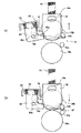
図1に、本発明のシート体搬送装置を副走査搬送機構として適用する画像記録装置の基本構成を示す。
図1に示される画像記録装置(以下、記録装置とする)10は、ロール状に券回されてマガジン内に収納された長尺な写真感光材料を、作製すべきプリントに応じた所定長に切断してカットシートとした後に、バックプリント(裏印字)を行い、次いで本発明のシート体搬送装置により2組のローラ対によって副走査搬送しながらデジタル走査露光を行い、露光済感光材料Zを現像機(プロセッサ)に供給する装置であって、感光材料供給部12、裏印字部14、本発明のシート体搬送装置を適用する副走査搬送手段16を有する記録部18および振分手段20を有する。
【0024】
なお、装置の基本的な構成を明瞭にするために図示を省略しているが、記録装置10には、搬送ローラ等の感光材料Zの搬送手段や搬送ガイド、感光材料検出のためのセンサ等、公知の画像記録装置に配置される各種の部材が、必要に応じて配置されている。ここで、搬送手段として設けられる搬送ローラの間隔は、感光材料Zの搬送方向に支障がないように、切断後のシート状感光材料Zのとりうる最小長さよりも小さく設定されていることはいうまでもない。
【0025】
感光材料供給部12には、乳剤面(感光面)を外側にしてロール状に巻回された長尺な感光材料Zを遮光性の筐体に収納してなるマガジン22aおよび22bをそれぞれ装填するための装填部24aおよび24bが配置される。ここで、マガジン22aおよび22b内にはそれぞれ感光材料Zの引き出し口に対応する位置に引き出しローラ対26aおよび26bが配置されている。そして、装填部24aおよび24bにそれぞれ対応するカッタ28aおよび28bが、それぞれ装填部24aおよび24bに装填されたマガジン22aおよび22bの引き出しローラ対26aおよび26bの下流側に近接するように配置される。
図1に示されるように、記録装置10においては、装填部24aの下方に装填部24bが配置されており、記録位置Xはその上方に位置している。
【0026】
図示例の記録装置10は、2つのマガジン22aおよび22bを装填可能な装置であって、両者は通常、サイズ(幅)、面種(シルクやマット等)、仕様(厚さやベースの種類等)等、互いに種類の異なる感光材料Zを収納するが、同種類の感光材料Zでもよいことはもちろんである。なお、図示例の記録装置10においては、装填可能なマガジン数は図示例の2個に限定されず、1個であってもよいし、あるいは3個以上のマガジンが装填可能であってもよい。
このような感光材料供給部12においては、引き出しローラ対26aおよび26bによって対応するマガジンの感光材料Zを引き出して、下流の裏印字部14に搬送する。この搬送は、カッタ28a,28bより下流に搬送された感光材料Zが作成するプリントに応じた長さになった時点で停止し、次いで、カッタ28a,28bが作動して、感光材料Zが所定長のカットシートとされる。
【0027】
図1に示される記録装置10は、2つのマガジン22aおよび22bの個々に対してカッタ28aおよび28bを設け、これらのマガジンから引き出された感光材料Zを別個のカッタ28a,28bでそれぞれ切断する構成としているが、本発明はこれに限定はされず、共通の1つのカッタで切断する構成としてもよい。
このように感光材料供給部12から引き出されて、切断されたシート状感光材料Zは、上方の裏印字部14に搬送される。
【0028】
裏印字部14は、感光材料Zの裏面(非乳剤面)に、写真の撮影日、プリント焼付日、コマ番号、フィルムID番号(符号)、撮影に使用したカメラのID番号、フォトプリンタのID番号等の各種の情報、いわゆるバックプリント情報(裏印字情報)を記録(裏印字)する部分である。
このような裏印字部14は、例えば、接触型の印字装置として、ドットインパクト方式の裏印字プリンタ30を用いることができ、ガイド32に案内されて搬送される感光材料Zに裏印字情報を記録するが、裏印字情報の記録方法および装置(プリンタ)はこれに限定されず、インクジェットプリンタ、熱転写プリンタ等、公知のフォトプリンタに用いられる裏印字情報の記録方法および装置が各種利用可能である。中でも、非接触であるために裏印字情報の記録が走査搬送に与える負荷変動を無くすことができる点で、インクジェットプリンタのような非接触型の記録方法および装置は好適に利用可能であり、特に、非水溶性で常温で固体の熱溶融性インクを用いたインクジェットプリンタは好ましく例示される。
また、裏印字部14は、新規格の新写真システム(Advanced Photo System) に対応して、2行以上の印字が可能に構成するのが好ましい。
【0029】
このようにして、所定長に切断され、裏印字情報が記録された感光材料Zは、次いで、記録部18(副走査搬送手段16)に搬送される。
記録部18は、露光光学ユニット(以下、露光ユニットという)34および本発明のシート体搬送装置を適用する副走査搬送手段16を有する。図示例の記録装置10において、露光ユニット34による画像記録は、シート状感光材料Zを走査搬送しつつ、デジタル画像データに応じて変調され、副走査搬送手段16による副走査搬送方向と略直交する主走査方向(図1の紙面と垂直方向)に偏向される光ビームを記録光Lとして、記録(露光)位置Xにおいて感光材料Zを走査露光する、いわゆるデジタル走査露光によって行われる。
【0030】
露光ユニット34は、このようなデジタル露光を行う光学ユニットであって、図示しないが、例えば、感光材料Zの赤(R)露光、緑(G)露光および青(B)露光のそれぞれに対応する光ビームを射出する光源、前記光源から射出された光ビームをデジタルの画像データに応じて変調するAOM(音響光学変調器)等の変調手段、変調された光ビームを副走査搬送方向と略直交する主走査方向に偏向するポリゴンミラー等の光偏向器、主走査方向に偏向された光ビームを記録位置X(走査線)上の所定位置に所定のビーム系で結像させるfθ(走査)レンズ等によって構成される、公知の光ビーム走査装置を用いることができる。
【0031】
なお、露光ユニット34は、このような光ビーム走査装置に限定されず、副走査搬送方向と直交する主走査方向に延在する各種の発光アレイや空間変調素子アレイ等を用いて、主走査方向に配列されるデジタル画像信号によって変調された複数の光ビームによって感光材料Zを露光する、デジタルの露光手段が各種利用可能である。具体的には、PDP(プラズマディスプレイ)アレイ、ELD(エレクトロルミネセントディスプレイ)アレイ、LED(発光ダイオード)アレイ、LCD(液晶ディスプレイ)アレイ、DMD(デジタルマイクロミラーデバイス)アレイ、レーザアレイ等を用いるデジタル露光手段などが例示される。
【0032】
図2に、副走査搬送手段16の概略側面図を示す。
副走査搬送手段16は、本発明のシート体搬送装置が適用され、本発明のシート状被走査体、すなわちシート体であるシート状感光材料Zを露光ユニット34の主走査方向の光走査に同期して主走査方向と略直交する副走査方向に挟持搬送するものであって、主走査線が画成される記録(主走査)位置Xを挟んでシート状感光材料Zの副走査方向の長さよりも短い間隔で配設される2組の上流側の搬送ローラ対(以下、第1ローラ対ともいう)36および下流側の搬送ローラ対(以下、第2ローラ対ともいう)38と、これらの2組の搬送ローラ対36と38との間の記録位置Xに配設される光走査ガイド40と、この記録位置Xに近接して上流側の第1ローラ対36と記録位置Xとの間に配設される、本発明の特徴とする押さえコロ対42と、2組の搬送ローラ対36と38とをシート状感光材料Zの進入・排出に合わせて開閉する開閉手段44と、押さえコロ対42の挟持力調整機構46と、搬送ガイド48と、第1および第2ローラ対36および38を同期駆動する同期駆動手段(図示せず)と、第1ローラ対36の上流側の所定位置に配設され、シート状感光材料Zの先端を検出する先端検出センサ(図示せず)を有する。
【0033】
図示例の本発明のシート体搬送装置を適用する副走査搬送手段16は、押さえコロ対42によってシート状感光材料Zのカールなどによる記録位置Xからの浮き等の深度方向の位置ずれを防止し、シート状感光材料Zを光走査ガイド40上の記録位置Xに正確に保持しつつ、搬送ローラ対36および38によって、主走査方向と略直交する副走査方向に挟持搬送する。ここで、前述のように、光ビームLは主走査方向に偏向されており、感光材料Zは、光ビームLによって2次元的に走査露光され、潜像が形成される。
【0034】
第1ローラ対36は、回転駆動される固定型の第1駆動ローラ36aとこれに摺接して従動回転する第1ニップローラ36bとを有し、第2ローラ対38は、回転駆動される固定型の第2駆動ローラ38aとこれに摺接して従動回転する第2ニップローラ38bとを有する。光走査ガイド40は、搬送ローラ対36および38の間に配置され、第1ローラ対36によって搬送される感光材料Zの先端をカールがあっても載置できるように低い位置から搬送下流側に向かって記録位置Xの高さ近傍まで上昇するとともに感光材料Zの先端を押さえコロ対42に案内する傾斜面部40aと押さえコロ対42に挟持されて搬送される感光材料Zを記録位置Xにおいて平面状に載置するための平面部40bとを持つ部材である。第1駆動ローラ36aと第2駆動ローラ38aとは、図示しない同期駆動手段によって同期駆動される。例えば、図示しないが、第1および第2駆動ローラ36aおよび38aをタイミングベルトで連結し、一方の駆動ローラを駆動源に直接または変速機構を介して連結することにより、同期駆動されるが、その具体的構成は特に限定されない。一方、第1および第2ニップローラ36bおよび38bは、タイミングベルト37で連結され、一方のニップローラが駆動ローラと当接して従動する際には、開放されたローラ対の退避したニップローラも同期駆動される駆動ローラも同様に回転する。
【0035】
押さえコロ対42は、第1ローラ対36と光走査ガイド40上の記録位置Xとの間、すなわち記録位置Xの上流側に配設され、搬送される感光材料Zに摺接して従動回転可能な小径の固定型のコロ(以下、固定コロという)42aと搬送される感光材料Zを固定コロ42aとの間で挟持しつつ感光材料Zに摺接して従動回転するとともに、感光材料Zの挟持力を調整可能な小径の押さえコロ42bとを有する。なお、押さえコロ対42は、可能な限り記録位置Xの近傍に配置されるのが好ましい。
【0036】
第1および第2ローラ対36および38の開閉手段44は、第1ローラ対36の第1ニップローラ36bに係合し、第1ニップローラ36bを第1駆動ローラ36aに対して進退させる第1カム機構50と、第2ローラ対38の第2ニップローラ38bに係合し、第2ニップローラ38bを第1駆動ローラ38aに対して進退させる第2カム機構52と、第1カム機構50および第2カム機構52を駆動する駆動機構54とを有する。
【0037】
第1カム機構50は、第1ニップローラ36bを回転可能に支持するとともに第1ニップローラ36bの進退方向、すなわち図中上下方向に往復動する第1ブラケット56と、第1ニップローラ36bを第1駆動ローラ36aに押圧する方向、すなわち図中下方向に第1ブラケット56を付勢する第1付勢ばね58と、第1ブラケット56に係合して固定軸59に対して回動する第1回動部材60と、この第1回動部材60に係合して第1ブラケット56を第1ニップローラ36bの退避方向、すなわち図中上方向に移動させるように第1回動部材60を回動させる偏芯カム62とを有する。第1ブラケット56と第1回動部材60との係合は、第1ブラケット56が図中上下方向にのみに往復するように第1ブラケット56に設けられた少し大きい長孔56aと第1回動部材60の一端に設けられたピン60aとによって行われる。その結果、第1ニップローラ36bの退避(離隔)、すなわち第1ブラケット56の図中上方向の移動は、偏芯カム62による第1回動部材60の回動によってそのピン60aが第1ブラケット56の長孔56aの図中上辺に当接して第1付勢ばね58の付勢力に抗して第1ブラケット56を持ち上げることによって行われるが、第1ニップローラ36bの進入(当接)、すなわち第1ブラケット56の図中下方向の移動は、偏芯カム62による第1回動部材60の回動とともに第1付勢ばね58による第1ブラケット56の図中下方向への付勢によって行われ、第1回動部材60のピン60aが第1ブラケット56の長孔56aの図中上辺から離れた後は第1付勢ばね58の付勢力のみによって行われる。
【0038】
第2カム機構52は、第2ニップローラ38bを回転可能に支持するとともに第2ニップローラ38bの進退方向、すなわち図中上下方向に往復動する第2ブラケット64と、第2ニップローラ38bを第2駆動ローラ38aに押圧する方向、すなわち図中下方向に第2ブラケット64を付勢する第2付勢ばね66と、第2ブラケット64に係合して固定軸59に対して回動する第2回動部材68と、この第2回動部材68に係合して第2ブラケット64を第2ニップローラ38bの退避方向、すなわち図中上方向に移動させるように第2回動部材68を回動させる、第1カム機構50と共通な偏芯カム62とを有する。すなわち第1カム機構50と第2カム機構52とは、1つの共通な偏芯カム62によって駆動される。共通な偏芯カム62は、第1ニップローラ36bと第2ニップローラ38bとを感光材料Zの搬送と同期して進退させるカムプロファイルを有する。また、第2ブラケット64と第2回動部材68との係合は、第2ブラケット64が図中上下方向にのみに往復するように第2ブラケット64に設けられた少し大きい長孔64aと第2回動部材68の一端に設けられたピン68aによって行われる。その結果、第2ニップローラ38bの進退も、第1ニップローラ36bと同様に行われる。すなわち第2ブラケット64の図中上方向の移動は、偏芯カム62による第2回動部材68の回動によって第2付勢ばね66の付勢力に抗して行われ、第2ブラケット64の図中下方向の移動は、始めは偏芯カム62による第2回動部材68の回動と第2付勢ばね66による付勢とによって行われ、最後は第2付勢ばね66の付勢力のみによって行われる。
【0039】
駆動機構54は、駆動源となる駆動モータ70と、駆動モータ70の駆動軸70aに取り付けられた歯車70bと噛合する大径歯車72aおよび大径歯車72aと同軸の小径歯車72bを持つ変速歯車72と、偏芯カム62の回動軸62aと同軸に設けられ、変速歯車72の小径歯車72bと噛合する歯車62bと、偏芯カム62の初期位置を検出する始点検出センサ74とを有し、感光材料Zの先端検出センサ(図示せず)による検出に同期して駆動モータ70が正逆回転して偏芯カム62を正逆回転させ、第1および第2回動部材60および68をそれぞれ回動し、第1および第2ブラケット56および64を上下動させる。こうして、第1および第2ローラ対36および38は、第1ニップローラ36bの第1駆動ローラ36aからの退避ならびに第2ニップローラ38bの第1駆動ローラ36aからの退避およびそれへの当接を行い、感光材料Zの先端の第1ローラ対36からの離脱およびその後端の第2ローラ対38への突入時の衝撃を防止して感光材料Zの挟持して副走査搬送する、いわゆるソフトランディング動作またはソフトニップ動作を行うことができる。
【0040】
押さえコロ対42およびその挟持力調整機構46は、本発明の最も特徴的な部分であって、シート状感光材料Zのカールによるその先端部分および後端部分の記録位置Xからの浮きを防止し、走査露光のための光ビームLの深度方向の位置ずれを排し、または極めて小さい許容限度まで低減してシート状感光材料Zの先端部分および後端部分であっても十分なる平面性を確保して副走査搬送を行い、高精度の画像記録を可能にするものである。
以下に、図2〜図6を参照して、押さえコロ対42およびその挟持力調整機構46をより詳細に説明する。
【0041】
まず、これらの図に示すように、挟持力調整機構46は、押さえコロ42aを回転自在に支持する第3揺動部材76と、押さえコロ42aを固定コロ42bに押圧するように第3揺動部材76を付勢する第3付勢ばね78と、この第3付勢ばね78の他端を固定するとともに第3揺動部材76の揺動軸76aを枢支し、第1カム機構50の第1ブラケット56に係合し固定揺動軸80aを中心にして揺動する第4揺動部材80とを有し、偏芯カム62による第1回動部材の回動を介した第1ブラケット56の上下動に同期して第3揺動部材76への第3付勢ばね78の付勢力の付加と開放とを行い、押さえコロ42aの固定コロ42bに対する押圧力の付加と開放、従って押さえコロ対42の感光材料Zの挟持力を調整するものである。
【0042】
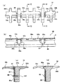
次に、図3は、図2に示す挟持力調整機構46の部分断面斜視図である。
図3に示すように、第4揺動部材80は、複数、例えば5個の第3揺動部材76とそれぞれ係合する複数の第3付勢ばね78がそれぞれ配置される複数の開口80bと、各開口80bの一辺(第4揺動部材80の長手方向の一辺)に設けられ、第3付勢ばね78の一端を係止する突起状係止部80cと、これらの開口80bの他辺(第4揺動部材80の短手方向の一辺)から垂下し、複数の第3揺動部材76の揺動軸76aを取付ける開孔部80dを持つ複数の垂下片80eと、短手方向の両端から垂下し、固定揺動軸80aに枢支される軸受用開孔部80fおよび第1ブラケット56との係合部80gを持つL字状のブラケット部80hとを有する。
【0043】
続いて、図4は、図3に示す押さえコロ対42および第3揺動部材76の斜視図である。
図3および図4に示すように、第3揺動部材76は、内部に第1ローラ対36の複数個に分割された第1ニップローラ36bの1つが挿入される開口部76bを持つコの字状本体76cと、本体76cの開放された両先端(図4中前方)の外側側面に立設され、押さえコロ42bを回転可能に支持する押さえコロ支持部76dと、本体76cの後端側(図4中後方)の両外側側面に立設され、第4揺動部材80の開孔部80dに取付けられる揺動軸76aを枢支する軸受用開孔部76eを持つブラケット部76fと、本体76cの後端側(図4中後方)から所定角度傾斜して立設され、開口部76bと逆側の背面で第3付勢ばね78の他端を係止する凸状係止部76gを持つ傾斜部76hとを有する。
図3に示すように、第3揺動部材76は、第4揺動部材80に図中下側から組み込まれ、第3揺動部材76の傾斜部76hの凸状係止部76gは、第4揺動部材80の開口80bから突出し、開口80bの突起状係止部80cにその一端が係止され、開口80bに配置される第3付勢ばね78の他端を係止する。
【0044】
図3および図4に示す例においては、押さえコロ対42の固定コロ42aおよび押さえコロ42bは、複数の小サイズの細分割コロに分割されており、固定コロ42aは、第3揺動部材76の両押さえコロ支持部76dで支持される押さえコロ42bの両端のみに設けられる2個の細分割コロである。なお、図3には第3揺動部材76および押さえコロ対42は、簡略化のため、1組しか図示されていないが、第4揺動部材80の全長に渡って複数組が設けられているのはもちろんである。
図5は、図3に示す押さえコロ対42の固定コロ42aと光走査ガイド40との関係を示す分解斜視図である。同図に示すように、細分割コロからなる固定コロ42aは、光走査ガイド40の傾斜面部40aおよび平面部40bの一部に穿設される凹部40cに回転可能に埋め込まれる。固定コロ42aを回転可能に支持する軸(固定ピン43)は、凹部40cの段部40dに載置され、図示しない部材で固定される。このように固定コロ42aを光走査ガイド40の凹部40cに埋め込むように支承することにより、また、固定コロ42aおよび押さえコロ42bの径をできるだけ小さくすることにより、押さえコロ対42の配設位置を可能な限り記録位置Xに近づけることができる。
もちろん、固定コロ42aは光走査ガイド40の凹部40cに回転可能に埋め込まれれば、固定コロ42aと軸とを一体としてこの軸を回転可能に支持して良いなど、どのような構成としても良い。
この時、細分割コロからなる複数の固定コロ42aは、図1に示す裏印字プリンタ30による感光材料Zの裏印字の転写がおこらないように、裏印字位置を外すように設けられるのが好ましい。
【0045】
その結果、副走査搬送される感光材料Zは、その裏面(乳剤面と逆側)が所定間隔で固定コロ42aに支持され、固定コロ42a間は光走査ガイド40の傾斜面部によって支持される一方、その乳剤面は記録位置Xの近傍の主走査線に沿った全長が押さえコロ42bによって押さえられるので、記録位置Xでのカール等による浮きなどの深度方向の位置ずれがほとんど防止できる。
なお、本発明において、固定コロ42aおよび押さえコロ42bの径や長さなどの寸法や形状や材質などは特に制限的ではない。しかし、図示例の記録装置10の場合には、押さえコロ42bは、直接感光材料Zの乳剤面に接触するので、乳剤面に影響を及ぼさない材質とする必要がある。従って、固定コロ42aおよび押さえコロ42bの径や長さなどの寸法や形状や材質などは、使用されるシート体やその使用目的に応じて適宜選択すればよい。
【0046】
図示例の押さえコロ対42の挟持力調整機構46は、副走査搬送手段16の2組の搬送ローラ対36および38による感光材料Zのソフトニップ動作を行う開閉手段44の第1カム機構50の第1ブラケット56の上下動に同期して駆動される。
図6(a)および(b)は、それぞれ第1ブラケット56による第4揺動部材80を介した第3揺動部材76の作用を示す概略部分側面図である。
図2および図6を参照して、開閉手段44による2組の搬送ローラ対36および38の感光材料Zのソフトニップ動作およびこれに同期した挟持力調整機構46による押さえコロ対42の感光材料Zの挟持力の調整について説明する。
【0047】
まず、記録装置10の記録動作に先立って、開閉手段44の駆動機構54の駆動モータ70が駆動され、始点検出センサ74によって検出される初期位置に偏芯カム62が設定される。この時、副走査搬送手段16の2組の搬送ローラ対36と38および押さえコロ対42は、いずれも図2に示すように閉じて付勢された状態にあり、開閉手段44および挟持力調整機構46の各部材も図2に示す状態にある。すなわち、挟持力調整機構46の第4揺動部材80の係合部80gは第1カム機構50の第1ブラケット56と係合し、第1付勢ばね58によって下方向に付勢され、その結果、第4揺動部材80で支持される第3付勢ばね78によって付勢された第3揺動部材76によって押さえコロ対42の押さえコロ42bは固定コロ42aに押圧される。
その後、図示しない先端検出センサによって、感光材料Zの先端が副走査搬送手段16の第1ローラ対36の上流の所定位置に来たことが検出されると、図示しない同期駆動手段によって同期駆動される第1および第2ローラ対36および38の回転数、従って感光材料Zの搬送量のカウントを開始する。なお、記録さるべき感光材料Zが一連の記録動作の最初である場合には、感光材料Zの先端検出センサの出力を基準として、駆動機構54の駆動モータ70も所定量図中左方向に回転し、偏芯カム62を所定量図中左方向に回転して第2回動部材68を図中左方向に回動させ、第2ブラケット64を図中上方向に移動させ、第2ニップローラ38bを第2駆動ローラ38aから退避させた初期状態となる。
【0048】
所定搬送量のカウント後、感光材料Zの先端は、付勢された第1ローラ対36の第1駆動ローラ36aとニップローラ36bと間に付勢力に抗して進入し、両ローラ36aと36bとによって挟持され、その結果、感光材料Zは同期駆動される第1駆動ローラ36aの回転に伴って下流側に搬送される。さらに感光材料Zが搬送されると、その先端は付勢された押さえコロ対42の固定コロ42aと押さえコロ42bとの間に付勢力に抗して進入する。さらに搬送されて、感光材料Zの先端が記録位置Xに達すると、露光ユニット34から射出される光ビームLによって露光走査が開始される。この時感光材料Zはその先端部分であっても、記録位置Xの直上流側において主走査線に沿った全長が押さえコロ対42の押さえコロ42bによって固定コロ42aおよび光走査ガイド40の平面部40b近傍の傾斜面部40aに押圧されているので、たとえ感光材料Zの先端部分がカールしていたとしても、記録位置Xではそこからの浮きを防止し、十分に平面状を保持することができるので、高い精度での露光走査ができ、高画質画像の記録ができる。
このような高精度の露光走査が副走査搬送される感光材料Zに続行される。
【0049】
感光材料Zへの高精度の露光走査の開始から所定量搬送されると、感光材料Zの先端が第2ローラ対38に近づき、感光材料Zの先端が、開放された第2ニップローラ38bと第2駆動ローラ38aとの間に進入する。それに同期して、駆動モータ70は逆転して所定量図中右方向に回転し、第2回動部材の逆方向の回動とともに第2付勢ばね66の付勢力によって第2ブラケット64を図中下方向に移動させ、搬送される感光材料Zの先端が第2ローラ対38の挟持点を越えると、第2ニップローラ38bを第2駆動ローラ38aに向かって付勢し、感光材料Zを確実に挟持する。この時、第2ニップローラ38bは、第2駆動ローラ38aと同期駆動される第1駆動ローラ36aによって従動回転される第1ニップローラ36bによってタイミングベルト37を介して同期回転されているので、感光材料Zと第2ニップローラ38bとの接触による衝撃が極めて小さく、位置ずれ等を生じさせることなく、感光材料Zをソフトに挟持することができる。
こうして、偏芯カム62は始点位置に戻り、第2ローラ対38は閉じ、第2ローラ対38および第2カム機構52は、図2に示す状態となる。
【0050】
さらに、感光材料Zが走査露光されつつ搬送され、感光材料Zの後端が、第1ローラ対36に近づき、上述した図示しない先端検出センサによって検出されると、駆動機構54の駆動モータ70が所定量図中左方向に回転し、偏芯カム62を所定量図中左方向に回転して第1回動部材60を図中左方向に回動させ、第1ブラケット56を図中上方向に移動させ、感光材料Zの後端の第1ローラ対36からの離脱に同期して、第1ニップローラ36bが第1駆動ローラ36aから退避して第1ローラ対36による感光材料Zの挟持を開放する。その結果、感光材料Zは第1ローラ対36から排出される時、第1ローラ対36は感光材料Zの挟持を開放しているので、感光材料Zの後端の第1ローラ対36の挟持からの離脱に伴う衝撃や位置ずれ等が発生することがない。こうして、第1ローラ対36から感光材料Zをソフトに離脱させ、排出することができる。
【0051】
この後、感光材料Zは、走査露光されつつさらに下流に搬送され、感光材料Zの後端が押さえコロ対42に近づく。
この時、図6(a)に示すように、第1ブラケット56の図中上方向への移動に伴って挟持力調整機構46の第4揺動部材80の係合部80gも上昇し、第4揺動部材80はその固定揺動軸80aを中心に図中左方向に回動し、第3揺動部材76の傾斜部76hの凸状係止部76gが、感光材料Zの後端の押さえコロ対42からの離脱に同期して、第4揺動部材80の側面部に当接する。このため、第3揺動部材76の傾斜部76hの凸状係止部76gと第4揺動部材80の開口80bの突起状係止部80cとの間に配置された第3付勢ばね78による第3揺動部材76の付勢力が解除される。その結果、第3揺動部材76はその揺動軸76aを中心に自由に揺動可能な状態となり、押さえコロ対42の押さえコロ42bの固定コロ42aへの付勢力、すなわち固定コロ42a上の感光材料Zへの押圧力は解除され、押さえコロ42bは固定コロ42a上の感光材料Zを押圧しない状態になる。なお、この時、押さえコロ42bは、固定コロ42a上の感光材料Zを自重で押さえる状態であってもよいし、固定コロ42a上の感光材料Zから完全に離れ、自重もかからない状態であってもよい。
こうして、感光材料Zは、押さえコロ対42から離脱し、排出される。この時にも、押さえコロ対42の感光材料Zの挟持力は、解除されているので、感光材料Zの後端の押さえコロ対42の挟持からの離脱に伴う衝撃や位置ずれ等が発生することがない。こうして、押さえコロ対42から感光材料Zをソフトに離脱させ、排出させることができる。
【0052】
この後、感光材料Zは、走査露光されつつさらに下流に搬送され、感光材料Zの後端が記録位置Xを越えると、露光ユニット34による光ビームの射出は停止し、感光材料Zの露光走査は終了する。露光走査が終了した後も、感光材料Zは第2ローラ対38によって下流に搬送されるが、それに同期して、駆動モータ70は逆転して所定量図中左方向に回転し、第1回動部材60の逆方向の回動とともに第1付勢ばね58の付勢力によって第1ブラケット56を図中下方向に移動させ、第1ニップローラ36bを第1駆動ローラ36aに当接させ、付勢する。この時、図6(b)に示すように、第1ブラケット56の図中下方向への移動に伴って、第4揺動部材80を図中右方向に回動させ、第3付勢ばね58の付勢力によって第3揺動部材76を図中右方向に回動するように付勢し、押さえコロ対42の押さえコロ42bを固定コロ42aに当接させ、付勢する。こうして偏芯カム62は始点位置に戻り、第1ローラ対36および押さえコロ対42は閉じ、第1ローラ対36、押さえコロ対42および第1カム機構50は、図2に示す状態となる。
【0053】
この後、感光材料Zはさらに下流に搬送され、第2ローラ対38から排出されると、直ちに、駆動機構54の駆動モータ70も所定量図中左方向に回転し、偏芯カム62を所定量図中左方向に回転して第2回動部材68を図中左方向に回動させ、第2ブラケット64を図中上方向に移動させ、第2ニップローラ38bを第2駆動ローラ38aから退避させ、初期状態に戻る。すなわち、第1および第2ローラ対36および38ならびに第1および第2カム機構50および52などを始めとして副走査搬送手段16は、初期状態に戻る。
こうして本発明のシート体搬送装置を適用する副走査搬送手段16の副走査搬送は行われる。
なお、搬送ローラ対36および38のニップローラ36aおよび38aを、少なくとも一方の搬送ローラ対の2個のローラが離間状態にあっても、駆動ローラ36bおよび38bと同期回転させる手段は、図示例のタイミングベルト37とプーリの組み合わせに限定されず、ニップローラ36aおよび38aを同期回転できるのであれば何でもよく、チェーンとスプロケットなどの組み合わせで連結してもよいし、アイドラや歯車などを用いるものであってもよい。
【0054】
このように、上流側の第1ローラ対36のみに挟持搬送される感光材料Zの先端や下流側の第2ローラ対38のみに挟持搬送される感光材料Zの後端が、カール等を有していたとしても、光走査ガイド40の記録位置Xの上流側の極近傍において押さえコロ対42によってカール等による浮きや深度方向の位置ずれを排し、感光材料Zを正確な記録位置Xにおいて常に平面状に保持することができるので、露光ユニット34からの射出光ビームLによって高精度に走査露光することができ、高画質画像を得ることができる。
さらに、感光材料Zの先端が下流側の第2ローラ対38に突入する際に、および、感光材料Zの後端が上流側の第1ローラ対36および押さえコロ対42から離脱する際に、感光材料Zの先端または後端に対応する位置の搬送ローラ対38または36の両ローラを同期回転させつつ離間させて挟持を開放し、次に接触させて挟持し、また押さえコロ対42の両コロの付勢力を解除して挟持を開放し、次に付勢力を付加して挟持する構成とすることにより、感光材料Zの先端が下流側の第2ローラ対38に突入する際、および感光材料Zの後端が上流側の第1ローラ対36および押さえコロ対42を離脱する際における負荷変動を防止し、この負荷変動に起因する露光位置ずれや露光ムラを防止し、さらに高画質画像を得ることができる。
【0055】
なお、第1および第2ローラ対36および38の開閉ならびに押さえコロ対42の挟持力の調整のシーケンスは、上記例に限定されず、種々のシーケンスで行うことができる。例えば、感光材料Zの先端の通過時に、第1ローラ対36の開閉を行ってもよいし、押さえコロ対42の挟持力の調整を行ってもよいし、感光材料Zの後端の通過時に、第2ローラ対38の開閉を行ってもよいし、さらには感光材料Zの先後端の通過による負荷変動の記録画像に与える影響が小さければ、第1および第2ローラ対36および38を予め接触させておき、感光材料Zをその後端が離脱するまで挟持する構成としてもよい。
このようにして、高精度の走査露光が行われた感光材料Zは、副走査搬送手段16から排出されて、その下流側に位置する振分手段20に搬送される。
【0056】
振分手段20は、感光材料Zを搬送方向(現像機92による搬送方向に対応)と直交する方向(以下、横方向とする)に振り分けるものである。
現在、写真のプリントに利用される一般的な銀塩写真感光材料では、現像処理と露光とでは現像処理のほうが時間がかかるため、連続的に露光を行うと、現像処理が間に合わない。
振分手段20は、この不都合を解消するために配置されるものであり、感光材料Zを横方向に振り分けて、搬送方向には重なる複数列にすることにより、現像装置における処理能力の向上、例えば、2列であれば単列の2倍弱、3列であれば3倍弱の処理を行うことを可能とし、現像処理と露光との処理時間差を相殺することができる。
【0057】
振分手段20における振分方法としては、各種のシート材の振分方法が利用可能であり、例えば、軸を中心に回転するターレットを用いて振り分ける方法や、感光材料Zの搬送手段を複数、例えば3つのブロックに分けて、その内の真ん中のブロックを横方向に移動して振り分ける方法等が例示される。また、感光材料Zを載置して搬送する下流方向への搬送手段としてのベルトコンベアと、吸盤等を利用して感光材料Zを持ち上げて横方向に搬送するリフト搬送手段とを用い、上流からベルトコンベアに搬入され所定位置に搬送された感光材料Zを、リフト搬送手段によって横あるいは斜め横(下流側)方向に搬送して、振り分ける方法も例示される。
【0058】
このようにして、振分手段20において、必要に応じて複数列に振り分けられた感光材料Zは、次いで、搬送ローラ対90によって現像機92に搬送され、感光材料Zに応じた、現像、定着、水洗等の各処理が施され、乾燥され、プリントとされる。
【0059】
本発明に係るシート体搬送装置を副走査搬送手段16として適用する記録装置10は、基本的に以上のように構成されるが、本発明はこれに限定されない。
例えば、副走査搬送手段16において記録位置Xの上流側近傍で記録位置Xからの光ビームLの深度方向の位置ずれを防止する手段は、図示例の押さえコロ対42およびその挟持力調整手段46に限定されず、光走査ガイド40に搬送される感光材料Zを搬送に合わせて押圧し、また押圧を開放する手段であれば何でもよいし、また、押さえコロ対42およびその挟持力調整手段46などの位置ずれ防止手段が記録位置Xを規定できれば、光走査ガイド40はなくてもよい。
【0060】
また、上述例においては、図1および図2に示すように、感光材料Z等のシート体の記録位置(光走査位置)Xからの深度方向の位置ずれを防止する位置ずれ防止手段である押さえコロ対42を、記録位置Xの上流側に設け、記録位置Xの上流側近傍で感光材料Zの浮き上がりなどを防止して、感光材料Zの記録位置Xからの光ビームLの深度方向の位置ずれを防止しているが、本発明はこれに限定されず、押さえコロ対42などの位置ずれ防止手段を下流側に設けてもよいし、上流側および下流側の両側に設けてもよい。しかし、ジャム等の懸念が減少し、画像記録ムラ等も発生しにくいので、押さえコロ対42などの位置ずれ防止手段を上流側に設けるのが好ましい。ここで、ジャムの懸念が減少するのは、下流側だとカールしているシート状感光材料Zの先端がぶつかり易いのに対し、上流側だと直前までガイドがあるからである。また、ムラが発生しにくいのは、押さえコロ対42がシート状感光材料Zを挟持した瞬間や挟持を開放する瞬間がムラになり易いが、挟持を開放する瞬間の方がムラに対して感度が低いので、上流側に設ける方がムラとして視認しにくいからである。
【0061】
また、上述した例においては、図2および図5に示すように、押さえコロ対42の固定コロ42aは、個々に傾斜面部40aおよび平面部40bを持つ光走査ガイド40に穿設される凹部40cに回転可能に埋め込まれているが、本発明はこれに限定されず、光走査ガイド40の代わりに、図7(a),(b),(c)および(d)に示すような光走査ガイド94に回転可能に取り付けるようにしても良い。
これらの図に示す光走査ガイド94は、傾斜面部94a、平面部94b、平面部94bから上流側に延出し、その先端側が下方に向かって湾曲する櫛葉状の曲爪94c、平面部94bから下流側に真っ直ぐ延出した櫛葉状の直爪94dおよび固定コロ42aを回転可能に埋め込む複数の凹部94eを備えている。
【0062】
光走査ガイド94の傾斜面部94aおよび平面部94bは、光走査ガイド40の傾斜面部40aおよび平面部40bとほぼ同じ形状を持つ。平面部94bは、感光材料Zを正確に記録位置Xに載置し、この記録位置Xにおいて感光材料Z上に露光ユニット34から射出される記録光ビームLによる主走査線を画成させるためのもので、平面部94bの中央部には、主走査方向に沿って主走査線となる記録位置Xが形成される。
櫛葉状に形成された複数の曲爪94cは、図2に示す副走査搬送手段16の第1ローラ対36のニップ点(駆動ローラ36aとニップローラ36bとの接触点)まで、平面部94bからぼぼ同一平面で上流側に延在し、このニップ点を越えて下方に湾曲してさらに上流まで延出する。また、図示例では、後端(先端側)が面取りされた直爪94dが、複数の曲爪94cに対応して平面部94bからぼぼ同一平面で下流側に延出するように櫛葉状に形成されている。
なお、その両側に凹部94eが設けられ、固定コロ42aが取り付けられる曲爪94cおよびこの曲爪94cに対応する直爪94dは、他の曲爪94cおよび直爪94dより幅広に形成される。
【0063】
ところで、光走査ガイド94の平面部94bと第1ローラ対36のニップ点(駆動ローラ36aの頂点)との間、または光走査ガイド94の平面部94bと第2ローラ対38のニップ点(駆動ローラ38aの頂点)との間に段差があると、画像記録ムラを発生させる原因となる。このため、光走査ガイド94の平面部94bは、第1ローラ対のニップ点、第2ローラ対のニップ点に対してそれぞれ同じまたは僅かに低くなるように設計されていると共に、櫛歯状の曲爪94cおよび直爪94dを設けることにより、感光材料Zを第1ローラ対36のニップ点において光走査ガイド94の曲爪94cにスムーズに載置して、先端の湾曲部分で平面部94bと同じ高さに案内し、そのまま高さを変えずに記録位置Xを規定する平面部94b上をスライドさせ、最終的に第2ローラ対のニップ点まで案内するので、段差によって記録位置Xでの感光材料Zの変動を生じさせることがなくなり、画像記録ムラの発生を防止することができる。
【0064】
凹部94eは、固定コロ42aを回転可能に埋め込むために、光走査ガイド94の基部に、かつ所定の広幅の曲爪94cの両側に設けられる。その一方の凹部94eには、図3に示す1組の押さえコロ42bの一方の端部の固定コロ42aが、他方の凹部94eは、隣の1組の押さえコロ42bの他方の端部の固定コロ42aが取り付けられる。なお、図3〜図5に示す例では、固定コロ42aは、個々に、光走査ガイド40の凹部40cの段部40dに固定された固定ピン43に回転可能に支持されるが、図7(a)〜(d)に示す例では、曲爪94cの両側に設けられる一対の凹部94eにそれぞれ埋め込まれる一対の固定コロ42aは、光走査ガイド94の曲爪94cの裏側に固定される固定ピン43の両端に回転可能に支持される。固定ピン43は、光走査ガイド94の曲爪94cの裏面に設けられ、一対の凹部94eを連絡する窪みに、固定部材95によって固定される。この固定部材95は、その長孔95aを光走査ガイド94に設けられたネジ孔94fにネジ96によってねじ止めすることにより、光走査ガイド94に固定される。この固定部材95は、複数の固定ピン43を同時に固定できるように一体の部材で構成されているが、個々に固定するようにしてもよい。また、一対の固定コロ42aを1個の固定ピン43で回転可能に支持しているが、個々に支持する構成であってもよいし、固定コロ42aを軸を取り付け、この軸を回転可能に支持する構成であってもよい。
【0065】
また、図示例の副走査搬送手段16においては、第1および第2ローラ対36および38の開閉手段44の第1および第2カム機構50および52は、共通の偏芯カム62を有し、この共通の偏芯カム62を1つの駆動モータ70を持つ駆動機構54によって駆動しているけれども、本発明はこれに限定されず、第1および第2カム機構50および52がそれぞれ個々に所定のカムプロファイルを持つカム部材を有し、個々のカム部材を1つの駆動源によって駆動するようにしてもよいし、各々のカム部材をそれぞれ独立した駆動源によって駆動するようにしてもよい。
また、上述した例では、第1および第2カム機構50および52では、各ローラ対のニップローラを回転自在に支持するブラケットを回動部材によって上下動させる構成としているが、本発明はこれに限定されず、ブラケットと回動部材とを一体化した揺動部材を用い、ニップローラの回転自在な支持と上下動とを同時におこなってもよい。また、図示例の開閉手段44では、第1カム機構50の第1回動部材60と第2カム機構52の第2回動部材68とを共通な固定軸59を中心にして回動しているが、別々の回転中心を有していてもよい。
【0066】
さらに、図示例では、深度方向位置ずれ防止手段である押さえコロ対42の挟持力調整手段46は、開閉手段44の第1カム機構50のブラケット56の上下動によって駆動されるように構成されるが、本発明はこれに限定されず、他の部材によって駆動されてもよいし、開閉手段44と独立した駆動源によって駆動されてもよい。また、図示例の押さえコロ対42の挟持力調整手段46は、第3揺動部材76によって押さえコロ対42の押さえコロ42bを回転自在に支持し、第4揺動部材80によって第3揺動部材76を揺動自在に支持する構成であるが、本発明はこれに限定されず、1つの揺動部材によって押さえコロ42bを回転自在に支持するとともに揺動して押さえコロ対42の挟持力を第1カム機構50による第1ローラ対36の開閉に合わせて、例えば、第1ブラケット56や第1回動部材60や両者を一体化した揺動部材、あるいは全く別の部材や駆動源によって駆動して調整するようにしてもよい。
【0067】
さらにまた、上述した図2、図6(a)および(b)に示す例においては、2組の第1および第2搬送ローラ対36および38の開閉手段44を、第1および第2カム機構50および52ならびに駆動機構54によって構成しているが、本発明は、これに限定されず、2組の搬送ローラ対36と38とをシート状感光材料Zの進入・排出に合わせて開閉できれば、どのようなもの(機構、手段、方法)でもよく、例えば、ソレノイドを用いる機構、ラックアンドピニオン機構(とその駆動機構)、リニアガイド機構(とその駆動機構)およびロータリソレノイドを用いる機構などで構成してもよい。
これらの機構を、第1搬送ローラ対36の搬送ローラ36bを接離方向、図示例では略上下に移動させる例を代表例として図8(a)〜図12に示し、これらの図を参照して以下に説明するが、第1搬送ローラ対36の駆動ローラ36a、第1搬送ローラ対36の両ローラ36a、36bを移動させる場合にも、第2搬送ローラ対38の駆動ローラ38aおよび搬送ローラ38bの少なくとも一方を移動させる場合にも適用可能なことは、もちろんである。
【0068】
図8(a)および(b)に示すソレノイドを用いる機構(電磁アクチュエータ)100は、ソレノイド102と、開閉手段44の搬送ローラ対36の搬送ローラ36bを回転可能に支持する第1ブラケット56と直接連結されるソレノイド102の可動ロッド104とを有する。図8(a)に示すように、第1ブラケット56が、非通電の状態で、図示しない付勢手段によって付勢され(例えば、図2に示すばね58によってばね付勢され)ていることにより、搬送ローラ対36の搬送ローラ36bと駆動ローラ36aとを互いに当接させることができる。一方、ソレノイド102に通電することにより、図8(b)に示すように、電磁力によって可動ロッド104をばね付勢力に抗して上方に所定距離引き上げ、可動ロッド104に係合された第1ブラケット56を引き上げて、搬送ローラ対36の搬送ローラ36bをその駆動ローラ36aから離脱させ、両ローラ36a、36b間を開くことができる。
なお、この機構100では、搬送ローラ36bと駆動ローラ36aとの離脱方向に第1ブラケット56を付勢し、非通電の状態で両ローラ36b、36a間を開き、通電状態で両ローラ36b、36a間を互いに当接させるように構成してもよい。また、ソレノイド102自体が往復方向のいずれかの方向に付勢されている場合には、第1ブラケット56を付勢する手段を設けなくてもよい。
【0069】
また、図9に示すソレノイドを用いる機構(電磁アクチュエータ)106のように、図8に示すソレノイドを用いる機構100で第1ブラケット56を直接上下に往復動させる代わりに、搖動部材108を介して第1ブラケット56を上下に往復動させてもよい。図9に示す機構106では、搖動部材108は中央側に支点109を有し、搖動部材108の一端にソレノイド102の可動ロッド104の先端が係合され、支点109に対して搖動部材108の他端に設けられたピン108aを第1ブラケット56の長孔56aに係合させている。この機構106では、ソレノイド102の通電、非通電により、可動ロッド104を上下動させ、揺動部材108を支点109として上下に揺動して、第1ブラケット56を上下動させ、第1搬送ローラ対36の搬送ローラ36bを駆動ローラ36aから接離させることができる。
【0070】
また、図10に示すラックアンドピニオン機構110は、図2、図6(a)および(b)に示す第1ブラケット56の代わりに用いられ、第1搬送ローラ対36の搬送ローラ36bを回転可能に支持するとともに、一側端に歯を有するラックブラケット112と、このラックブラケット112の歯と噛合するピニオン114と、このピニオン114とを有し、この機構110は、ピニオン114と噛合する歯車116aと、この歯車116aを駆動する駆動モータ116とを有する駆動機構によって駆動される。この機構110では、駆動モータ116の時計回り(例えば正転)または反時計回り(例えば逆転)の回転に伴って、歯車116aが正逆回転し、歯車116aと噛合するピニオン114が逆正回転して、ピニオン114と噛合するラックブラケット112が上下に往復動することにより、第1搬送ローラ対36の搬送ローラ36bを駆動ローラ36aから接離させることができる。
【0071】
また、図11に示すリニアガイド機構118は、図2、図6(a)および(b)に示す第1ブラケット56の代わりに用いられ、第1搬送ローラ対36の搬送ローラ36bを回転可能に支持するブラケット120の一側端に固定されるトラベリングナット122と、このトラベリングナット122の雌ねじ部と螺合するドライブスクリュー124とを有し、この機構118は、ドライブスクリュー124の一端(上端)に取り付けられ、このドライブスクリュー124を回転する駆動モータ126からなる駆動機構によって駆動される。この機構110では、駆動モータ126の時計回り(例えば正転)または反時計回り(例えば逆転)の回転に伴って、その回転軸に直結されたドライブスクリュー124が正逆回転し、これに螺合するトラベリングナット122が上下に往復動して、ブラケット120を上下動させることにより、第1搬送ローラ対36の搬送ローラ36bを駆動ローラ36aから接離させることができる。
【0072】
また、図12に示すロータリーソレノイドを用いる機構(電磁アクチュエータ)128は、ロータリーソレノイド130と、このロータリーソレノイド130の回転軸130aにその一端が固定され、その他端に設けられたピン132aが第1ブラケット56の長孔56aに係合される搖動部材132とを有する。ここで、搖動部材132は、直接、ロータリーソレノイド130の回転軸130aを中心にして回動するように、その一端が直接回転軸130aに固定される。この機構128では、ロータリーソレノイド130の通電、非通電により、回転軸130a回動させ、揺動部材132を回転軸132aを中心にして直接回動させて揺動部材132の他端(係合ピン132a)を略う上下方向に揺動して、第1ブラケット56を上下動させ、第1搬送ローラ対36の搬送ローラ36bを駆動ローラ36aから接離させることができる。
【0073】
また、上述した例では、光走査位置(記録位置X)から深度方向の位置ずれを防止する、本発明の特徴とする位置ずれ防止手段として、シート状感光材料Zを副走査搬送する2組の搬送ローラ対36と38との間の記録位置Xに近接して配設される押さえコロ対42を、開閉手段44によって2組の搬送ローラ対36と38とがそれぞれ感光材料Zの進入・排出に合わせて開閉される副走査搬送手段16に設けているが、本発明はこれに限定されず、2組の搬送ローラ対の間に配設され、記録位置Xからの深度方向の位置ずれを防止できれば、押さえコロ対42などの位置ずれ防止手段が設けられる2組の搬送ローラ対は個々に開閉手段を有せず、それぞれ独立して開閉する副走査搬送手段でなくてもよく、例えば、一方のみが開閉されてもよいし、両方とも開閉しないものであってもよい。
さらにまた、上述した例では、本発明のシート体搬送装置を副走査搬送手段16として記録装置10に適用しているが、本発明はこれに限定されず、画像読取装置などのように光ビーム走査等の光走査を行う光走査装置の副走査搬送手段や副走査搬送機構として適用可能なことはもちろんである。
【0074】
以上、本発明に係るシート体搬送装置について好適な実施の形態を挙げて詳細に説明したが、本発明はこれらの実施の形態に限定はされず、本発明の要旨を逸脱しない範囲において、種々の改良や設計の変更を行ってもよいのはもちろんである。
【0075】
【発明の効果】
以上詳述したように、本発明によれば、所定位置において、シート状感光材料などのシート体に対してレーザビームなどの光ビームによる光走査を行って、画像読取や画像記録等を行う光ビーム走査装置に用いられる副走査搬送機構として好適なものであって、シート体の先端部分および後端部分においても、シート体の有するカールの影響を排し、カール等によるシート体の先端部分や後端部分の光走査位置からの浮きなどの深度方向の位置ずれを排し、または極めて小さい許容限度まで低減し、シート体に十分なる平面性を確保しつつ円滑かつ高精度に副走査搬送を行うことができる。
しかも、本発明によれば、このような十分な平面性が確保された円滑かつ高精度なシート体の副走査搬送を、複雑な機構を必要とせず、簡単かつ小型コンパクトで安価な装置構成で実現できる。その結果、本発明によれば、高精度の画像読取や画像記録を能率良く、かつ低コストで実現できる。
【0076】
特に、感光材料をカットシートとした後に、デジタル走査露光や裏印字情報の記録等を行う、デジタルフォトプリンタ等に利用される画像記録装置に適用すれば、シート状感光材料の先端部分および/または後端部分においても濃度ムラの無い、高画質な画像記録を行うことができる。
【図面の簡単な説明】
【図1】 本発明のシート体搬送装置が副走査搬送手段として適用される画像記録装置の一実施の形態の基本構成を示す概念図である。
【図2】 図1に示す画像記録装置の副走査搬送手段の概略側面図である。
【図3】 図2に示す副走査搬送手段の挟持力調整機構の部分断面斜視図である。
【図4】 図3に示す挟持力調整機構の押さえコロ対および第3揺動部材の斜視図である。
【図5】 図3に示す押さえコロ対の固定コロと光走査ガイドとの関係を示す分解斜視図である。
【図6】 (a)および(b)は、それぞれ図2に示す副走査搬送手段の第1ブラケットによる第4揺動部材を介した第3揺動部材の作用を示す概略部分側面図である。
【図7】 (a)、(b)、(c)および(d)は、それぞれ図3に示す押さえコロ対の固定コロの光走査ガイドへの別の取付け状態を示す概略上面図、概略正面図、図7(a)の7C−7C線概略断面図および図7(a)の7D−7D線概略断面図である。
【図8】 (a)および(b)は、それぞれ図2に示す第1ローラ対の開閉手段の駆動系の別の実施例の作用を示す概略部分側面図である。
【図9】 図2に示す第1ローラ対の開閉手段の駆動系の別の実施例の作用を示す概略部分側面図である。
【図10】 図2に示す第1ローラ対の開閉手段の駆動系の別の実施例の作用を示す概略部分側面図である。
【図11】 図2に示す第1ローラ対の開閉手段の駆動系の別の実施例の作用を示す概略部分側面図である。
【図12】 図2に示す第1ローラ対の開閉手段の駆動系の別の実施例の作用を示す概略部分側面図である。
【符号の説明】
10 (画像)記録装置
12 感光材料供給部
14 裏印字部
16 副走査搬送手段
18 記録部
20 振分手段
22a,22b マガジン
24a,24b 装填部
26a,26b 引き出しローラ対
28a,28b カッタ
30 裏印字プリンタ
32 ガイド
34 露光ユニット
36,38,84,86 搬送ローラ対
36a,38a 駆動ローラ
36b,38b ニップローラ
40,94 光走査ガイド
42 押さえコロ対
42a 固定コロ
42b 押さえコロ
44 開閉手段
46 挟持力調整機構
48 搬送ガイド
50,52 カム機構
54 駆動機構
56,64 ブラケット
58,66,78 付勢ばね
59,62a,70a 軸
60,68 回動部材
62 偏芯カム
62a,70b,72a,72b 歯車
70 駆動モータ
72 変速歯車
74 始点検出センサ
76,80 揺動部材
90 搬送ローラ対
92 現像機[0001]
BACKGROUND OF THE INVENTION
The present invention relates to a sheet-like object to be scanned, that is, a sheet-body conveying device that sub-scans and conveys a sheet body with two pairs of rollers in order to record or read an image by irradiating the sheet body with a light beam, Specifically, light beam scanning of an image recording apparatus that records an image on a sheet body or an image reading apparatus that reads an image recorded on the sheet body by optically scanning the sheet body with a light beam deflected or arranged in a one-dimensional direction. The apparatus belongs to the technical field of sheet conveying apparatus.
[0002]
[Prior art]
At present, in a radiation image information reading apparatus, a stimulable phosphor sheet in which radiation energy is stored as image information is irradiated with excitation light such as laser light, and the stored radiation energy is excited and emitted. Emission light is detected by a photodetector such as a photomultiplier, and radiation image information is read photoelectrically. At this time, in the light beam scanning device of the radiation image information reading device, in order to read the radiation image information accumulated in the stimulable phosphor sheet two-dimensionally, the laser beam deflected in a one-dimensional direction is accumulated. The phosphor sheet is irradiated with the main scanning and the accumulative phosphor sheet is sub-scanned and conveyed in a direction substantially orthogonal to the main scanning direction. As a sub-scanning conveyance mechanism in this light beam scanning device, there is a sheet body conveyance device that sub-scans and conveys a sheet body such as a stimulable phosphor sheet by two pairs of rollers disposed at intervals shorter than the length in the sub-scanning direction. (See, for example, JP-A-62-135064, JP-A-62-167150, and JP-A-63-67859).
[0003]
In such a sheet conveying apparatus, an impact which is easily received when a sheet body such as a stimulable phosphor sheet having a predetermined thickness enters between the pair of rollers and leaves the pair of rollers is easily received. In order to prevent the occurrence, the one roller of the roller pair, that is, the nip roller, is retracted from the other roller, that is, the fixed roller, when the sheet member enters and leaves the roller pair. In this way, the occurrence of an impact on the sheet body is prevented, and as a result, the occurrence of vibration and positional deviation of the sheet body is prevented, and the smooth and highly accurate sub-scan conveyance of the sheet body is achieved. Reading is enabled. Further, Japanese Patent Application Laid-Open No. 5-281635 related to the present applicant discloses that a sub-scanning conveyance mechanism using two pairs of rollers at the time of entering and leaving between the pair of rollers of the sheet member. A compact sheet conveying apparatus having a simple configuration that selectively retracts a nip roller with one actuator is disclosed.
[0004]
On the other hand, in the field of image recording, an image taken on a photographic film (hereinafter referred to as film) such as a negative film or a reversal film is baked on a photosensitive material such as photographic paper and then developed to obtain a finished photographic print. Up to now, analog photo printers that expose a film-supported image onto a photosensitive material (direct exposure) have been used as printers. Currently, a film-supported image is an image such as a CCD of an image reading device such as a scanner. Digitally obtained by a light beam scanning device of an image recording device (printing device) after photoelectrically reading by a sensor, converting it to digital image data, and applying this digital image data to a predetermined image processing by an image processing device. The photosensitive material is scanned and exposed by a recording light beam modulated based on the image data. Recording a latent image) is subjected to a developing treatment by the developing device, a digital photo printer that outputs as a finished photographic prints have been put to practical use by the applicant.
[0005]
In this digital photo printer, after film is read photoelectrically and converted into digital image information (data), gradation correction and the like are performed by digital image processing to determine exposure conditions. Therefore, various image processing such as print image editing such as composition of multiple images and image division by digital image processing, color / density adjustment, edge enhancement, dodging, peripheral light amount correction, distortion aberration correction, and chromatic aberration correction are also free. It has excellent features such as being able to output prints that are freely processed according to the application. Further, it has excellent characteristics such that image data of a print image can be supplied to a computer or the like, and can be stored in a recording medium such as a floppy disk.
In addition, the digital photo printer has excellent features such as higher resolution, color / density reproducibility, and better image quality than conventional direct exposure printing. is doing.
[0006]
However, the digital photo printer according to the present applicant has such an excellent feature, and as an image recording apparatus, a long photosensitive material wound in a roll shape is conveyed as it is by sub-scanning conveyance. The main scanning with the light beam deflected in a one-dimensional direction is continuously repeated, and the long photosensitive material is not cut in the middle, and is exposed using an image printing apparatus that records a large number of images. Since the photosensitive material is developed with a long length, the long photosensitive material is finally cut into a predetermined length corresponding to the image to obtain a single finished print, so that a large amount of processing can be performed with extremely high efficiency. However, since the apparatus configuration is increased in size, operation is difficult to perform a small amount of processing, and there is a problem that the apparatus is expensive and large in size and is not suitable as an apparatus for small amount processing.
[0007]
For this reason, even in a digital photo printer, an apparatus in which a long photosensitive material is cut into a cut sheet corresponding to a single print, and then a cut sheet-like photosensitive material is subjected to light beam scanning exposure. The realization of a printing apparatus (hereinafter referred to as a sheet-type image recording apparatus) capable of downsizing the configuration and significantly reducing the apparatus cost and running cost is strongly desired.
In such a sheet type image recording apparatus, two pairs of rollers used as the sub-scanning conveyance mechanism of the light beam scanning apparatus of the radiation image information reading apparatus disclosed in Japanese Patent Laid-Open No. 5-281635 described above are used. Application of a sheet conveying apparatus is considered.
[0008]
[Problems to be solved by the invention]
By the way, in such a sheet type image recording apparatus, since the photosensitive material wound in a roll shape is cut into a sheet having a predetermined length, one sheet-like photosensitive material has a completely flat shape. Rather, it is slightly curled. That is, it is customary that the light-sensitive material is wound in a roll shape with the emulsion surface on the outside, and when this is cut into a sheet, a convex curl with the emulsion surface on the outside remains. .
[0009]
When the sheet-shaped photosensitive material thus curled is sub-scanned and conveyed by the sheet conveyance device using two pairs of rollers arranged at a predetermined interval as disclosed in Japanese Patent Laid-Open No. 5-281635, the sheet is obtained. When the image exposure is performed from the front end of the sheet-shaped photosensitive material, the front end of the sheet-shaped photosensitive material passes through the upstream roller pair, and reaches the downstream roller pair from the exposure position between the roller pair and Until the trailing edge of the sheet-like photosensitive material passes through the upstream roller pair and reaches the downstream roller pair from the exposure position, the sheet-like photosensitive material is only on one side of the upstream and downstream roller pairs, respectively. Since the image scanning exposure is performed at the image recording (exposure) position while being sub-scanned and transported in a so-called cantilever state, the photosensitive material is curled at the front end portion and the rear end portion. Since the optical path length varies in the direction, there is a problem that unevenness of exposure, thus density unevenness.
[0010]
In other words, by using such a sheet transport device, exposure unevenness (density unevenness) due to load fluctuations such as impact, vibration, and positional deviation at the time of entry or separation between roller pairs of sheet-like photosensitive material can be reduced to some extent. However, since it does not prevent curling of the photosensitive material that is the sheet-like object to be scanned, there is still a problem that the flatness at the exposure position cannot be sufficiently ensured and uneven exposure occurs.
As described above, when the sheet-shaped photosensitive material is sub-scanned and conveyed by the two pairs of rollers, if the distance between the two pairs of rollers is wide, the portion where the sheet-shaped photosensitive material is conveyed in a cantilever state increases. Therefore, the curl of the sheet-like photosensitive material appears prominently at the exposure position, and scanning exposure is performed on this curled and raised portion, and the exposure cannot be performed with a uniform and appropriate optical path length. There is a problem that exposure unevenness is likely to occur at the front end portion and the rear end portion of the photosensitive material, and a high-quality print cannot be obtained.
[0011]
An object of the present invention is to solve the above-mentioned problems of the prior art, use two sets of roller pairs as a sub-scanning conveyance mechanism of a light beam scanning device, and to scan a sheet-like object such as a sheet-like photosensitive material, that is, a sheet body Can be transported smoothly and with high accuracy, and the influence of curling of the sheet body is eliminated, that is, the leading edge portion and the trailing edge portion of the sheet body due to curling and the like are lifted from the optical scanning position in the depth direction. It is possible to perform sub-scanning conveyance while ensuring sufficient flatness in the sheet body, eliminating the positional deviation of the image, or reducing it to an extremely small allowable limit. An object of the present invention is to provide a sheet conveying apparatus that is optimal for image reading and image recording.
[0012]
[Means for Solving the Problems]
To achieve the above object, the present inventionThe first form ofAre a first roller pair and a second roller that are disposed in a sub-scanning direction that is substantially orthogonal to the one-dimensional direction with a distance shorter than the length of the sheet body in the sub-scanning direction. A sheet body conveying apparatus that is sandwiched between a pair and performs sub-scanning conveyance,
A misalignment prevention means disposed between the first roller pair and the second roller pair, and preventing misalignment in the depth direction from the optical scanning position of the sheet member;
The misregistration prevention means includes
A pair of pressing rollers configured to be rotatable and a pressing roller capable of adjusting and rotating the holding force of the sheet body between the fixing rollers and holding the sheet body at the optical scanning position. ,
A third swinging member that rotatably supports the pressing roller, a third biasing unit that biases the third swinging member so as to press the pressing roller against the fixed roller, and a third biasing unit. An urging force adding means for applying and releasing the urging force of the third swing member is provided, engages with the pressing roller, and adjusts the clamping force of the sheet body between the pressing roller and the fixed roller. A holding force adjusting mechanism and an adjusting mechanism.The third oscillating member is divided into a plurality of parts in the main scanning direction, and each of the third oscillating members has the pressing roller, the fixed roller, and the third urging means.It is an object of the present invention to provide a sheet conveying apparatus.
Here, in the sheet transport apparatus according to the first aspect, the pressing roller for each of the third swinging members is a finely divided roller that is further subdivided into smaller sizes, and the fixed roller is the third roller. It is preferable that the two finely divided rollers are provided only at both ends of the swing member and come into contact with the finely divided rollers at both ends of the pressing roller.
According to a second aspect of the present invention, a sheet body that is optically scanned in a one-dimensional direction is disposed in a sub-scanning direction substantially orthogonal to the one-dimensional direction at an interval shorter than the length of the sheet body in the sub-scanning direction. A sheet body conveying device that is sandwiched between a first roller pair and a second roller pair to perform sub-scanning conveyance,
A first roller disposed on the upstream side of the second roller pair and rotationally driven, a first nip roller that is movable forward and backward with respect to the first roller, and the first nip roller are engaged with the first nip roller, and the first nip roller is engaged with the sheet. The first roller pair having a first opening / closing means for opening and closing the first roller pair by advancing and retreating according to the conveyance of the body;
A second roller disposed on the downstream side of the first roller pair and driven to rotate, a second nip roller that can be moved forward and backward with respect to the second roller, and the second nip roller are engaged with the second nip roller. The second roller pair having a second opening / closing means for opening and closing the second roller pair by advancing and retreating according to the conveyance of the body;
A misalignment prevention means disposed between the first roller pair and the second roller pair, and preventing misalignment in the depth direction from the optical scanning position of the sheet member;
The misregistration prevention means includes
A pair of pressing rollers configured to be rotatable and a pressing roller capable of adjusting and rotating the holding force of the sheet body between the fixing rollers and holding the sheet body at the optical scanning position. ,
A third swinging member that rotatably supports the pressing roller, a third biasing unit that biases the third swinging member so as to press the pressing roller against the fixed roller, and a third biasing unit. An urging force adding means for applying and releasing the urging force of the third swing member is provided, engages with the pressing roller, and adjusts the clamping force of the sheet body between the pressing roller and the fixed roller. A clamping force adjusting mechanism
The first opening / closing means includes
A first cam mechanism and a driving means for the first cam mechanism; the second opening / closing means is a second cam mechanism and a driving means for the second cam mechanism;
The urging force adding means applies and releases the urging force of the third oscillating member by the third urging means by the first oscillating member of the first cam mechanism. Transport A device is provided.
According to a third aspect of the present invention, a sheet body that is optically scanned in a one-dimensional direction is disposed in a sub-scanning direction substantially orthogonal to the one-dimensional direction at an interval shorter than the length of the sheet body in the sub-scanning direction. A sheet body conveying device that is sandwiched between a first roller pair and a second roller pair to perform sub-scanning conveyance,
A first roller disposed on the upstream side of the second roller pair and rotationally driven, a first nip roller that is movable forward and backward with respect to the first roller, and the first nip roller are engaged with the first nip roller, and the first nip roller is engaged with the sheet. The first roller pair having a first opening / closing means for opening and closing the first roller pair by advancing and retreating according to the conveyance of the body;
A second roller disposed on the downstream side of the first roller pair and driven to rotate, a second nip roller that can be moved forward and backward with respect to the second roller, and the second nip roller are engaged with the second nip roller. The second roller pair having a second opening / closing means for opening and closing the second roller pair by advancing and retreating according to the conveyance of the body;
A misalignment prevention means disposed between the first roller pair and the second roller pair, and preventing misalignment in the depth direction from the optical scanning position of the sheet member;
The misregistration prevention means includes
A pair of pressing rollers configured to be rotatable and a pressing roller capable of adjusting and rotating the holding force of the sheet body between the fixing rollers and holding the sheet body at the optical scanning position. ,
A third swinging member that rotatably supports the pressing roller, a third biasing unit that biases the third swinging member so as to press the pressing roller against the fixed roller, and a third biasing unit. An urging force adding means for applying and releasing the urging force of the third swing member is provided, engages with the pressing roller, and adjusts the clamping force of the sheet body between the pressing roller and the fixed roller. A clamping force adjusting mechanism
The first opening / closing means includes a first swing member that rotatably supports the first nip roller, and a first swing member that engages with the first swing member and moves the first nip roller forward and backward with respect to the first roller. A first cam mechanism comprising one cam member and a drive means for the first cam mechanism;
The second opening / closing means includes a second swinging member that rotatably supports the second nip roller, and a second swinging member that engages with the second swinging member to advance and retract the second nip roller relative to the second roller. A second cam mechanism comprising two cam members and a drive means for the second cam mechanism,
The first cam member and the second cam member have a single common rotation shaft, and the common drive source which is a rotation drive source is connected to the common rotation shaft,
Furthermore, the driving means of the first cam mechanism and the driving means of the second cam mechanism are configured to drive the first cam mechanism and the second cam mechanism in an integrated manner so that the first roller pair and the second roller pair are driven. Is a single common drive source that selectively opens and closes
The urging force adding means applies and releases the urging force of the third oscillating member by the third urging means by the first oscillating member of the first cam mechanism. A conveying device is provided.
According to a fourth aspect of the present invention, a sheet body that is optically scanned in a one-dimensional direction is arranged in a sub-scanning direction substantially orthogonal to the one-dimensional direction at an interval shorter than the length of the sheet body in the sub-scanning direction. A sheet body conveying device that is sandwiched between a first roller pair and a second roller pair to perform sub-scanning conveyance,
A first roller disposed on the upstream side of the second roller pair and rotationally driven, a first nip roller that is movable forward and backward with respect to the first roller, and the first nip roller are engaged with the first nip roller, and the first nip roller is engaged with the sheet. The first roller pair having a first opening / closing means for opening and closing the first roller pair by advancing and retreating according to the conveyance of the body;
A second roller disposed on the downstream side of the first roller pair and driven to rotate, a second nip roller that is movable forward and backward with respect to the second roller, and the second nip roller are engaged with the second nip roller. The second roller pair having a second opening / closing means for opening and closing the second roller pair by advancing and retreating according to the conveyance of the sheet body;
A misalignment prevention means disposed between the first roller pair and the second roller pair, and preventing misalignment in the depth direction from the optical scanning position of the sheet member;
The misregistration prevention means includes
A pair of pressing rollers configured to be rotatable and a pressing roller capable of adjusting and rotating the holding force of the sheet body between the fixing rollers and holding the sheet body at the optical scanning position. ,
A third swinging member that rotatably supports the pressing roller, a third biasing unit that biases the third swinging member so as to press the pressing roller against the fixed roller, and a third biasing unit. An urging force adding means for applying and releasing the urging force of the third swing member is provided, engages with the pressing roller, and adjusts the clamping force of the sheet body between the pressing roller and the fixed roller. A clamping force adjusting mechanism
The first opening / closing means includes a first swing member that rotatably supports the first nip roller, and a first swing member that engages with the first swing member and moves the first nip roller forward and backward with respect to the first roller. A first cam mechanism comprising one cam member and a drive means for the first cam mechanism;
The second opening / closing means includes a second swinging member that rotatably supports the second nip roller, and a second swinging member that engages with the second swinging member to advance and retract the second nip roller relative to the second roller. A second cam mechanism comprising two cam members and a drive means for the second cam mechanism,
The first cam member and the second cam member have a single common rotation shaft, and the common drive source which is a rotation drive source is connected to the common rotation shaft,
Furthermore, the driving means of the first cam mechanism and the driving means of the second cam mechanism are configured to drive the first cam mechanism and the second cam mechanism in an integrated manner so that the first roller pair and the second roller pair are driven. Is a single common drive source that selectively opens and closes
The first swinging member rotatably supports the first nip roller, reciprocates in the contact / separation direction with respect to the first roller, and the first bracket and the first cam member. A first rotating member that rotates together, and first urging means that urges the first bracket so as to press the first nip roller against the first roller,
The second swing member rotatably supports the second nip roller, and reciprocates in the contact / separation direction with respect to the second roller, and the second bracket and the second cam member. A second rotating member that rotates together, and second urging means that urges the second bracket so as to press the second nip roller against the second roller,
The biasing force adding means further includes the fourth swing member that engages with the first bracket of the first swing member of the first cam mechanism, and the third swing member is the fourth swing member. The swing member has a swing shaft, and the third urging means urges the third swing member against the fourth swing member, and reciprocates the first bracket. It is an object of the present invention to provide a sheet conveying apparatus characterized in that the urging force of the third swinging member is added and released by the third urging means.
[0013]
The first to fourth formsIn the sheet transport apparatus, the positional deviation prevention means is disposed between the first roller pair and the second roller pair and at least one of the upstream side and the downstream side of the optical scanning position of the sheet body. More preferably, it is preferably disposed between the first roller pair and the second roller pair and upstream of the optical scanning position of the sheet member.
Further, the present invention is the above-described sheet transport apparatus, and further is a light that is disposed between the first roller pair and the second roller pair and supports the sheet body from the lower surface thereof at the optical scanning position. Having a scanning guide;
The position deviation prevention means is a means for preventing the sheet body from floating from the optical scanning guide.
[0014]
The present invention also provides the aboveOf the first formSheet transport deviceIn,
The first roller pair is arranged on the upstream side of the second roller pair, and includes a first roller that is rotationally driven and a first nip roller that is movable forward and backward with respect to the first roller, and is associated with the first nip roller. A first opening / closing means for opening and closing the first roller pair by moving the first nip roller forward and backward in accordance with the conveyance of the sheet member;
The second roller pair is disposed on the downstream side of the first roller pair, and includes a second roller that is rotationally driven and a second nip roller that is movable forward and backward with respect to the second roller. The second roller pair is associated with the second nip roller. A second opening / closing means for opening and closing the second roller pair by advancing and retracting the second nip roller in accordance with the conveyance of the sheet member,
Furthermore, it is preferable to have.
[0015]
the above1st to 4th formsIn the sheet transport apparatus, the first opening / closing means is any one of a cam mechanism and its driving means, a solenoid, a rotary solenoid, a rack and pinion mechanism and its driving means, a linear guide mechanism and its driving means, The second opening / closing means is preferably one of a cam mechanism and its driving means, a solenoid, a rotary solenoid, a rack and pinion mechanism and its driving means, a linear guide mechanism and its driving means.
Also,In the sheet transport apparatus according to the first aspect,Preferably, the first opening / closing means is a first cam mechanism and a driving means for the first cam mechanism, and the second opening / closing means is a second cam mechanism and a driving means for the second cam mechanism.
[0016]
Also,In the sheet conveying apparatus according to the first or second aspect,The drive means of the first cam mechanism and the drive means of the second cam mechanism select the first roller pair and the second roller pair by driving the first cam mechanism and the second cam mechanism integrally. Preferably, it is a single common drive source that is opened and closed automatically.
Also,In the sheet conveying apparatus according to the first or second aspect,The first cam mechanism includes a first swinging member that rotatably supports the first nip roller, and a first swinging member that engages with the first swinging member and moves the first nip roller forward and backward with respect to the first roller. 1 cam member,
The second cam mechanism includes a second swinging member that rotatably supports the second nip roller, and a second swinging member that engages with the second swinging member and moves the second nip roller forward and backward with respect to the second roller. 2 cam members,
Preferably, the first cam member and the second cam member have a single common rotation shaft, and the common drive source, which is a rotation drive source, is connected to the common rotation shaft.
[0017]
here,In the sheet conveying apparatus of the first to third embodiments,The first swinging member rotatably supports the first nip roller, reciprocates in the contact / separation direction with respect to the first roller, and the first bracket and the first cam member. A first rotating member that rotates together, and first urging means that urges the first bracket so as to press the first nip roller against the first roller,
The second swing member rotatably supports the second nip roller, and reciprocates in the contact / separation direction with respect to the second roller, and the second bracket and the second cam member. It is preferable to include a second rotating member that rotates together and a second urging unit that urges the second bracket so as to press the second nip roller against the second roller.
Also,In the first to fourth sheet conveying apparatuses,Preferably, the first cam member and the second cam member are a single common eccentric cam, and the first rotating member and the second rotating member have a single common rotating shaft. .
[0019]
here,In the sheet transport apparatus according to the first aspect,The urging force adding means adds and releases the urging force of the third swing member by the third urging means in accordance with advancement and retraction of the first nip roller with respect to the first roller by the first cam mechanism. preferable.
Also,In the sheet transport apparatus according to the first aspect,Preferably, the urging force applying means applies and releases the urging force of the third oscillating member by the third urging member by the first oscillating member of the first cam mechanism.
Also,In the sheet transport apparatus according to the first aspect,The biasing force adding means further includes the fourth swing member that engages with the first bracket of the first swing member of the first cam mechanism, and the third swing member is the fourth swing member. The swing member has a swing shaft, and the third urging means urges the third swing member against the fourth swing member, and reciprocates the first bracket. It is preferable to apply and release the biasing force of the third swing member by the third biasing means.
[0020]
Here, in the sheet conveying apparatus according to the first to fourth embodiments,The pressing roller and the fixing roller are preferably divided rollers.
Moreover, it is preferable that the fixed roller is rotatably supported by the optical scanning guide.
[0021]
Also,In the first to fourth sheet conveying apparatuses,When the sheet conveying device is a sub-scanning conveying mechanism of an image recording device, the sheet member is a photosensitive material, and the image recording device includes a back printing unit, the fixed roller is formed by the back printing unit. It is preferable to be provided at a position where the back printing position is removed.
Also,In the first to fourth sheet conveying apparatuses,The optical scanning guide is preferably provided in a plurality in the one-dimensional direction, and has a comb-like bent claw that extends upstream in the sub-scanning direction and has a tip curved inward. It is preferable to have a plurality of comb-like straight claws provided in the direction and extending downstream in the sub-scanning direction.
[0022]
DETAILED DESCRIPTION OF THE INVENTION
The sheet conveying apparatus according to the present invention will be described below in detail based on a preferred embodiment shown in the accompanying drawings.
[0023]
FIG. 1 shows a basic configuration of an image recording apparatus to which the sheet transport apparatus of the present invention is applied as a sub-scan transport mechanism.
An image recording apparatus (hereinafter referred to as a recording apparatus) 10 shown in FIG. 1 has a long photographic photosensitive material wound in a roll and stored in a magazine in a predetermined length corresponding to a print to be produced. After cutting into a cut sheet, back printing (back printing) is performed, and then digital scanning exposure is performed while carrying out sub-scanning conveyance with two pairs of rollers by the sheet conveying apparatus of the present invention. An apparatus for supplying to a developing machine (processor), including a photosensitive
[0024]
Although not shown for the sake of clarity of the basic configuration of the apparatus, the
[0025]
The photosensitive
As shown in FIG. 1, in the
[0026]
The
In such a photosensitive
[0027]
The
The sheet-like photosensitive material Z thus drawn and cut from the photosensitive
[0028]
The
The
Further, it is preferable that the
[0029]
In this way, the photosensitive material Z that has been cut to a predetermined length and recorded with the back printing information is then conveyed to the recording unit 18 (sub-scanning conveying means 16).
The
[0030]
The
[0031]
The
[0032]
FIG. 2 shows a schematic side view of the
The sub-scan transport means 16 is applied with the sheet transport apparatus of the present invention, and synchronizes the sheet-shaped scanned body of the present invention, that is, the sheet-shaped photosensitive material Z which is a sheet body, with optical scanning in the main scanning direction of the
[0033]
The sub-scanning conveying means 16 to which the sheet conveying apparatus of the present invention of the illustrated example is applied prevents positional deviation in the depth direction such as floating from the recording position X due to curling of the sheet-like photosensitive material Z by the
[0034]
The
[0035]
The pair of pressing
[0036]
The opening / closing means 44 of the first and second roller pairs 36 and 38 engages with the
[0037]
The
[0038]
The
[0039]
The
[0040]
The
Below, with reference to FIGS. 2-6, the
[0041]
First, as shown in these drawings, the clamping
[0042]
Next, FIG. 3 is a partial cross-sectional perspective view of the clamping
As shown in FIG. 3, the
[0043]
4 is a perspective view of the
As shown in FIGS. 3 and 4, the third swinging
As shown in FIG. 3, the
[0044]
In the example shown in FIGS. 3 and 4, the fixing
FIG. 5 is an exploded perspective view showing the relationship between the fixed
Of course, as long as the fixed
At this time, it is preferable that the plurality of fixed
[0045]
As a result, the back surface (opposite side of the emulsion surface) of the photosensitive material Z to be transported in the sub-scan is supported by the fixed
In the present invention, dimensions, shapes, materials, etc., such as the diameter and length of the fixed
[0046]
The holding
6A and 6B are schematic partial side views showing the action of the third rocking
With reference to FIGS. 2 and 6, the soft nip operation of the photosensitive material Z of the two pairs of conveying
[0047]
First, prior to the recording operation of the
Thereafter, when it is detected by a leading edge detection sensor (not shown) that the leading edge of the photosensitive material Z has reached a predetermined position upstream of the
[0048]
After the predetermined conveyance amount is counted, the leading edge of the photosensitive material Z enters between the
Such high-precision exposure scanning is continued for the photosensitive material Z to be transported in the sub-scanning direction.
[0049]
When the photosensitive material Z is conveyed by a predetermined amount from the start of the high-precision exposure scanning, the leading edge of the photosensitive material Z approaches the
Thus, the
[0050]
Further, when the photosensitive material Z is conveyed while being scanned and exposed, the rear end of the photosensitive material Z approaches the
[0051]
Thereafter, the photosensitive material Z is conveyed further downstream while being subjected to scanning exposure, and the rear end of the photosensitive material Z approaches the
At this time, as shown in FIG. 6A, as the
Thus, the photosensitive material Z is detached from the
[0052]
Thereafter, the photosensitive material Z is conveyed further downstream while being subjected to scanning exposure. When the rear end of the photosensitive material Z exceeds the recording position X, the light beam emission by the
[0053]
Thereafter, when the photosensitive material Z is further conveyed downstream and discharged from the
Thus, the sub-scanning conveyance of the sub-scanning conveyance means 16 to which the sheet material conveying apparatus of the present invention is applied is performed.
The means for rotating the nip
[0054]
As described above, the leading edge of the photosensitive material Z that is nipped and conveyed only by the upstream
Further, when the leading end of the photosensitive material Z enters the
[0055]
The sequence of opening / closing the first and second roller pairs 36 and 38 and adjusting the holding force of the
In this way, the photosensitive material Z that has been subjected to high-accuracy scanning exposure is discharged from the
[0056]
The distributing
At present, in general silver salt photographic light-sensitive materials used for photographic printing, the development processing and the exposure require more time, so the development processing is not in time when the exposure is continuously performed.
The allocating means 20 is arranged to eliminate this inconvenience. The photosensitive material Z is distributed in the horizontal direction to form a plurality of rows overlapping in the transport direction, thereby improving the processing capability in the developing device. For example, if it is two rows, it is possible to perform processing that is slightly less than twice that of a single row, and if it is three rows, it is possible to cancel the processing time difference between development processing and exposure.
[0057]
As a sorting method in the sorting means 20, various sheet material sorting methods can be used. For example, a sorting method using a turret that rotates around an axis, a plurality of photosensitive material Z conveying means, For example, a method of dividing the block into three blocks and moving the middle block of the blocks in the horizontal direction is exemplified. In addition, a belt conveyor as a downstream conveying means for loading and conveying the photosensitive material Z, and a lift conveying means for lifting the photosensitive material Z using a sucker or the like and conveying it in the lateral direction, are used from upstream. An example is a method in which the photosensitive material Z carried into the belt conveyor and transported to a predetermined position is transported in the lateral or oblique lateral (downstream) direction by the lift transport means and distributed.
[0058]
In this manner, the photosensitive material Z distributed in a plurality of rows as necessary in the
[0059]
The
For example, the means for preventing the positional deviation in the depth direction of the light beam L from the recording position X in the vicinity of the upstream side of the recording position X in the sub-scanning conveying means 16 is the
[0060]
In the above-described example, as shown in FIGS. 1 and 2, as shown in FIG. 1 and FIG. The
[0061]
Further, in the above-described example, as shown in FIGS. 2 and 5, the fixing
The
[0062]
The
The plurality of
In addition, the
[0063]
Incidentally, between the
[0064]
The
[0065]
In the illustrated sub-scanning conveying means 16, the first and
In the above-described example, the first and
[0066]
Further, in the illustrated example, the clamping force adjusting means 46 of the
[0067]
Furthermore, in the example shown in FIG. 2, FIG. 6A and FIG. 6B described above, the opening / closing means 44 of the two pairs of first and second conveying
These mechanisms are shown in FIGS. 8A to 12 as representative examples in which the conveying
[0068]
The mechanism (electromagnetic actuator) 100 using the solenoid shown in FIGS. 8A and 8B is directly connected to the
In this
[0069]
Further, like the mechanism (electromagnetic actuator) 106 using the solenoid shown in FIG. 9, the
[0070]
A rack and
[0071]
Further, the
[0072]
Further, a mechanism (electromagnetic actuator) 128 using a rotary solenoid shown in FIG. 12 has a
[0073]
Further, in the above-described example, two sets of sheet-shaped photosensitive material Z are transported in the sub-scanning manner as the positional deviation prevention means that prevents the positional deviation in the depth direction from the optical scanning position (recording position X). The
Furthermore, in the above-described example, the sheet transport apparatus of the present invention is applied to the
[0074]
As described above, the sheet conveying apparatus according to the present invention has been described in detail with reference to preferred embodiments. However, the present invention is not limited to these embodiments, and various modifications can be made without departing from the gist of the present invention. Of course, it is possible to make improvements and design changes.
[0075]
【The invention's effect】
As described above in detail, according to the present invention, at a predetermined position, light that scans a sheet body such as a sheet-like photosensitive material with a light beam such as a laser beam to perform image reading, image recording, or the like. It is suitable as a sub-scanning conveyance mechanism used in a beam scanning apparatus, and also eliminates the influence of curl of the sheet body at the front end portion and the rear end portion of the sheet body, Eliminates position shift in the depth direction, such as floating from the optical scanning position of the rear end part, or reduces it to an extremely small allowable limit, ensuring smoothness and high precision while ensuring sufficient flatness of the sheet body. It can be carried out.
In addition, according to the present invention, the smooth and highly accurate sheet body sub-scanning conveyance with such sufficient flatness can be achieved with a simple, small, and compact apparatus configuration without requiring a complicated mechanism. realizable. As a result, according to the present invention, highly accurate image reading and image recording can be realized efficiently and at low cost.
[0076]
In particular, if it is applied to an image recording apparatus used for a digital photo printer or the like that performs digital scanning exposure, recording of back print information, etc. after making the photosensitive material into a cut sheet, the leading end portion of the sheet-like photosensitive material and / or It is possible to perform high-quality image recording without density unevenness at the rear end portion.
[Brief description of the drawings]
FIG. 1 is a conceptual diagram illustrating a basic configuration of an embodiment of an image recording apparatus to which a sheet conveying apparatus of the present invention is applied as a sub-scanning conveying unit.
2 is a schematic side view of a sub-scanning conveying unit of the image recording apparatus shown in FIG.
3 is a partial cross-sectional perspective view of a clamping force adjusting mechanism of the sub-scanning conveying unit shown in FIG.
4 is a perspective view of a pair of pressing rollers and a third rocking member of the clamping force adjusting mechanism shown in FIG. 3;
5 is an exploded perspective view showing a relationship between a fixed roller and a light scanning guide of the pair of pressing rollers shown in FIG. 3. FIG.
6A and 6B are schematic partial side views showing the action of the third rocking member through the fourth rocking member by the first bracket of the sub-scanning conveying unit shown in FIG. 2, respectively. .
7 (a), (b), (c) and (d) are respectively a schematic top view and a schematic front view showing another attachment state of the pair of pressing rollers shown in FIG. 3 to the optical scanning guide. FIG. 7 is a schematic sectional view taken along line 7C-7C in FIG. 7A and a schematic sectional view taken along
8A and 8B are schematic partial side views showing the operation of another embodiment of the drive system of the opening / closing means of the first roller pair shown in FIG. 2, respectively.
FIG. 9 is a schematic partial side view showing the operation of another embodiment of the drive system of the opening / closing means of the first roller pair shown in FIG. 2;
10 is a schematic partial side view showing the operation of another embodiment of the drive system of the opening / closing means of the first roller pair shown in FIG. 2; FIG.
11 is a schematic partial side view showing the operation of another embodiment of the drive system of the opening / closing means of the first roller pair shown in FIG. 2; FIG.
12 is a schematic partial side view showing the operation of another embodiment of the drive system of the opening / closing means of the first roller pair shown in FIG. 2; FIG.
[Explanation of symbols]
10 (Image) recording device
12 Photosensitive material supply unit
14 Back printing section
16 Sub-scanning conveying means
18 Recording section
20 Sorting means
22a, 22b Magazine
24a, 24b loading section
26a, 26b Pull-out roller pair
28a, 28b Cutter
30 Back printer
32 Guide
34 Exposure unit
36, 38, 84, 86 Pair of transport rollers
36a, 38a Driving roller
36b, 38b Nip roller
40, 94 Optical scanning guide
42 Pressing roller pair
42a Fixed roller
42b Pressing roller
44 Opening and closing means
46 Nipping force adjustment mechanism
48 Transport Guide
50, 52 Cam mechanism
54 Drive mechanism
56, 64 bracket
58, 66, 78 Biasing spring
59, 62a, 70a shaft
60, 68 Rotating member
62 Eccentric cam
62a, 70b, 72a, 72b gears
70 Drive motor
72 transmission gear
74 Start point detection sensor
76, 80 Oscillating member
90 Conveying roller pair
92 Developer
Claims (30)
前記第1ローラ対と第2ローラ対との間に配設され、前記シート体の光走査位置からの深度方向の位置ずれを防止する位置ずれ防止手段を有し、
前記位置ずれ防止手段は、
回転可能な固定コロおよびこの固定コロとの間の前記シート体の挟持力を調整可能かつ回転可能な押さえコロから構成され、前記シート体を挟持して前記光走査位置に保持する押さえコロ対と、
前記押さえコロを回転自在に支持する第3揺動部材、前記押さえコロを前記固定コロに押圧するように前記第3揺動部材を付勢する第3付勢手段及びこの第3付勢手段による前記第3揺動部材の付勢力の付加と開放とを行う付勢力付加手段を備え、前記押さえコロに係合し、この押さえコロと前記固定コロとの間の前記シート体の挟持力を調整する挟持力調整機構とを有し、
前記第3揺動部材は、前記主走査方向に対して複数個に分割され、各第3揺動部材毎に前記押さえコロ、前記固定コロおよび前記第3付勢手段を有することを特徴とするシート体搬送装置。A first roller pair and a second roller pair, which are disposed in a sub-scanning direction substantially orthogonal to the one-dimensional direction, and a sheet roller that is optically scanned in the one-dimensional direction is spaced at an interval shorter than the length of the sheet body in the sub-scanning direction. A sheet body conveying device that is nipped by and sub-scanned and conveyed,
A misalignment prevention means disposed between the first roller pair and the second roller pair, and preventing misalignment in the depth direction from the optical scanning position of the sheet member;
The misregistration prevention means includes
A pair of pressing rollers configured to be rotatable and a pressing roller capable of adjusting and rotating the holding force of the sheet body between the fixing rollers and holding the sheet body at the optical scanning position. ,
A third swinging member that rotatably supports the pressing roller, a third biasing unit that biases the third swinging member so as to press the pressing roller against the fixed roller, and a third biasing unit. An urging force adding means for applying and releasing the urging force of the third swing member is provided, engages with the pressing roller, and adjusts the clamping force of the sheet body between the pressing roller and the fixed roller. possess a clamping force adjusting mechanism,
The third oscillating member is divided into a plurality of parts in the main scanning direction, and each of the third oscillating members includes the pressing roller, the fixed roller, and the third urging means. Sheet body conveying device.
前記第1ローラ対は、前記第2ローラ対の上流側に配置され、回転駆動される第1ローラおよびこの第1ローラに対して進退自在な第1ニップローラから構成され、前記第1ニップローラに係合し、この第1ニップローラを前記シート体の搬送に合わせて進退させて前記第1ローラ対を開閉する第1開閉手段と、
前記第2ローラ対は、前記第1ローラ対の下流側に配置され、回転駆動される第2ローラおよびこの第2ローラに対して進退自在な第2ニップローラから構成され、前記第2ニップローラに係合し、この第2ニップローラを前記シート体の搬送に合わせて進退させて前記第2ローラ対を開閉する第2開閉手段とを、
さらに有することを特徴とするシート体搬送装置。The sheet conveying apparatus according to claim 1 or 2 ,
The first roller pair is arranged on the upstream side of the second roller pair, and includes a first roller that is rotationally driven and a first nip roller that can move forward and backward with respect to the first roller, and is associated with the first nip roller. A first opening / closing means that opens and closes the first roller pair by moving the first nip roller forward and backward in accordance with the conveyance of the sheet member;
The second roller pair includes a second roller that is disposed downstream of the first roller pair, is driven to rotate, and a second nip roller that is movable forward and backward with respect to the second roller, and is associated with the second nip roller. A second opening / closing means for opening and closing the second roller pair by advancing and retracting the second nip roller in accordance with the conveyance of the sheet member,
Furthermore, the sheet | seat body conveying apparatus characterized by having.
前記第2カム機構は、前記第2ニップローラを回転自在に支持する第2揺動部材と、この第2揺動部材に係合して前記第2ニップローラを前記第2ローラに対して進退させる第2カム部材とを備え、
前記第1カム部材および前記第2カム部材は、単一な共通回転軸を有し、この共通回転軸に回転駆動源である前記共通駆動源を連結することを特徴とする請求項6に記載のシート体搬送装置。The first cam mechanism includes a first swinging member that rotatably supports the first nip roller, and a first swinging member that engages with the first swinging member and moves the first nip roller forward and backward with respect to the first roller. 1 cam member,
The second cam mechanism includes a second swinging member that rotatably supports the second nip roller, and a second swinging member that engages with the second swinging member and moves the second nip roller forward and backward with respect to the second roller. 2 cam members,
It said first cam member and said second cam member has a single common rotational axis, according to claim 6, characterized in that coupling the common rotation axis is a rotation drive source said common drive source Sheet body conveying device.
前記第2揺動部材は、前記第2ニップローラを回転自在に支持し、前記第2ローラに対して接離方向に往復動する第2ブラケットと、この第2ブラケットおよび前記第2カム部材と係合して回動する第2回動部材と、前記第2ニップローラを前記第2ローラに押圧するように前記第2ブラケットを付勢する第2付勢手段とを備えることを特徴とする請求項7に記載のシート体搬送装置。The first swinging member rotatably supports the first nip roller, reciprocates in the contact / separation direction with respect to the first roller, and the first bracket and the first cam member. A first rotating member that rotates together, and first urging means that urges the first bracket so as to press the first nip roller against the first roller,
The second swing member rotatably supports the second nip roller, and reciprocates in the contact / separation direction with respect to the second roller, and the second bracket and the second cam member. 2. A second rotating member that rotates together, and a second urging unit that urges the second bracket so as to press the second nip roller against the second roller. 8. The sheet conveying apparatus according to 7 .
前記第2ローラ対の上流側に配置され、回転駆動される第1ローラ、この第1ローラに対して進退自在な第1ニップローラおよび前記第1ニップローラに係合し、この第1ニップローラを前記シート体の搬送に合わせて進退させて前記第1ローラ対を開閉する第1開閉手段を有する前記第1ローラ対と、
前記第1ローラ対の下流側に配置され、回転駆動される第2ローラ、この第2ローラに対して進退自在な第2ニップローラおよび前記第2ニップローラに係合し、この第2ニップローラを前記シート体の搬送に合わせて進退させて前記第2ローラ対を開閉する第2開 閉手段を有する前記第2ローラ対と、
前記第1ローラ対と第2ローラ対との間に配設され、前記シート体の光走査位置からの深度方向の位置ずれを防止する位置ずれ防止手段を有し、
前記位置ずれ防止手段は、
回転可能な固定コロおよびこの固定コロとの間の前記シート体の挟持力を調整可能かつ回転可能な押さえコロから構成され、前記シート体を挟持して前記光走査位置に保持する押さえコロ対と、
前記押さえコロを回転自在に支持する第3揺動部材、前記押さえコロを前記固定コロに押圧するように前記第3揺動部材を付勢する第3付勢手段及びこの第3付勢手段による前記第3揺動部材の付勢力の付加と開放とを行う付勢力付加手段を備え、前記押さえコロに係合し、この押さえコロと前記固定コロとの間の前記シート体の挟持力を調整する挟持力調整機構とを有し、
前記第1開閉手段は、第1カム機構とこの第1カム機構の駆動手段であり、前記第2開閉手段は、第2カム機構とこの第2カム機構の駆動手段であり、
前記付勢力付加手段は、前記第1カム機構の前記第1揺動部材によって前記第3付勢手段による前記第3揺動部材の付勢力の付加と開放とを行うことを特徴とするシート体搬送装置。A first roller pair and a second roller pair, which are disposed in a sub-scanning direction substantially orthogonal to the one-dimensional direction, and a sheet roller that is optically scanned in the one-dimensional direction is spaced at an interval shorter than the length of the sheet body in the sub-scanning direction. A sheet body conveying device that is nipped by and sub-scanned and conveyed,
A first roller disposed on the upstream side of the second roller pair and rotationally driven, a first nip roller that is movable forward and backward with respect to the first roller, and the first nip roller are engaged with the first nip roller, and the first nip roller is engaged with the sheet. The first roller pair having a first opening / closing means for opening and closing the first roller pair by advancing and retreating according to the conveyance of the body;
A second roller disposed on the downstream side of the first roller pair and driven to rotate, a second nip roller that can be moved forward and backward with respect to the second roller, and the second nip roller are engaged with the second nip roller. said second pair of rollers having a second opening closed unit by forward and backward in accordance with the conveyance of the body for opening and closing the second pair of rollers,
A misalignment prevention means disposed between the first roller pair and the second roller pair, and preventing misalignment in the depth direction from the optical scanning position of the sheet member;
The misregistration prevention means includes
A pair of pressing rollers configured to be rotatable and a pressing roller capable of adjusting and rotating the holding force of the sheet body between the fixing rollers and holding the sheet body at the optical scanning position. ,
A third swinging member that rotatably supports the pressing roller, a third biasing unit that biases the third swinging member so as to press the pressing roller against the fixed roller, and a third biasing unit. An urging force adding means for applying and releasing the urging force of the third swing member is provided, engages with the pressing roller, and adjusts the clamping force of the sheet body between the pressing roller and the fixed roller. and a clamping force adjusting mechanism,
The first opening / closing means is a first cam mechanism and a driving means for the first cam mechanism, and the second opening / closing means is a second cam mechanism and a driving means for the second cam mechanism,
The urging force adding means applies and releases the urging force of the third oscillating member by the third urging means by the first oscillating member of the first cam mechanism. Conveying device.
前記第2カム機構は、前記第2ニップローラを回転自在に支持する第2揺動部材と、この第2揺動部材に係合して前記第2ニップローラを前記第2ローラに対して進退させる第2カム部材とを備え、
前記第1カム部材および前記第2カム部材は、単一な共通回転軸を有し、この共通回転軸に回転駆動源である前記共通駆動源を連結することを特徴とする請求項14に記載のシート体搬送装置。The first cam mechanism includes a first swinging member that rotatably supports the first nip roller, and a first swinging member that engages with the first swinging member and moves the first nip roller forward and backward with respect to the first roller. 1 cam member,
The second cam mechanism includes a second swinging member that rotatably supports the second nip roller, and a second swinging member that engages with the second swinging member and moves the second nip roller forward and backward with respect to the second roller. 2 cam members,
It said first cam member and said second cam member has a single common rotational axis, according to claim 14, characterized in that coupling the common rotation axis is a rotation drive source said common drive source Sheet body conveying device.
前記第2揺動部材は、前記第2ニップローラを回転自在に支持し、前記第2ローラに対して接離方向に往復動する第2ブラケットと、この第2ブラケットおよび前記第2カム部材と係合して回動する第2回動部材と、前記第2ニップローラを前記第2ローラに押圧するように前記第2ブラケットを付勢する第2付勢手段とを備えることを特徴とする請求項15に記載のシート体搬送装置。The first swinging member rotatably supports the first nip roller, reciprocates in the contact / separation direction with respect to the first roller, and the first bracket and the first cam member. A first rotating member that rotates together, and first urging means that urges the first bracket so as to press the first nip roller against the first roller,
The second swing member rotatably supports the second nip roller, and reciprocates in the contact / separation direction with respect to the second roller, and the second bracket and the second cam member. A second rotating member that rotates together, and a second urging unit that urges the second bracket so as to press the second nip roller against the second roller. 15. A sheet conveying apparatus according to 15 .
前記第2ローラ対の上流側に配置され、回転駆動される第1ローラ、この第1ローラに対して進退自在な第1ニップローラおよび前記第1ニップローラに係合し、この第1ニップローラを前記シート体の搬送に合わせて進退させて前記第1ローラ対を開閉する第1開閉手段を有する前記第1ローラ対と、
前記第1ローラ対の下流側に配置され、回転駆動される第2ローラ、この第2ローラに対して進退自在な第2ニップローラおよび前記第2ニップローラに係合し、この第2ニップローラを前記シート体の搬送に合わせて進退させて前記第2ローラ対を開閉する第2開閉手段を有する前記第2ローラ対と、
前記第1ローラ対と第2ローラ対との間に配設され、前記シート体の光走査位置からの深度方向の位置ずれを防止する位置ずれ防止手段を有し、
前記位置ずれ防止手段は、
回転可能な固定コロおよびこの固定コロとの間の前記シート体の挟持力を調整可能かつ回転可能な押さえコロから構成され、前記シート体を挟持して前記光走査位置に保持する押さえコロ対と、
前記押さえコロを回転自在に支持する第3揺動部材、前記押さえコロを前記固定コロに押圧するように前記第3揺動部材を付勢する第3付勢手段及びこの第3付勢手段による前記第3揺動部材の付勢力の付加と開放とを行う付勢力付加手段を備え、前記押さえコロに係合し、この押さえコロと前記固定コロとの間の前記シート体の挟持力を調整する挟持力調整機構とを有し、
前記第1開閉手段は、前記第1ニップローラを回転自在に支持する第1揺動部材と、この第1揺動部材に係合して前記第1ニップローラを前記第1ローラに対して進退させる第1カム部材とを備える第1カム機構とこの第1カム機構の駆動手段であり、
前記第2開閉手段は、前記第2ニップローラを回転自在に支持する第2揺動部材と、この第2揺動部材に係合して前記第2ニップローラを前記第2ローラに対して進退させる第2カム部材とを備える第2カム機構とこの第2カム機構の駆動手段であり、
前記第1カム部材および前記第2カム部材は、単一な共通回転軸を有し、この共通回転軸に回転駆動源である前記共通駆動源を連結し、
さらに、前記第1カム機構の駆動手段および前記第2カム機構の駆動手段は、前記第1カム機構および前記第2カム機構を一体的に駆動させて前記第1ローラ対と前記第2ローラ対を選択的に開閉させる単一な共通駆動源であり、
前記付勢力付加手段は、前記第1カム機構の前記第1揺動部材によって前記第3付勢手段による前記第3揺動部材の付勢力の付加と開放とを行うことを特徴とするシート体搬送装置。A first roller pair and a second roller pair, which are disposed in a sub-scanning direction substantially orthogonal to the one-dimensional direction, and a sheet roller that is optically scanned in the one-dimensional direction is spaced at an interval shorter than the length of the sheet body in the sub-scanning direction. A sheet body conveying device that is nipped by and sub-scanned and conveyed,
A first roller disposed on the upstream side of the second roller pair and rotationally driven, a first nip roller that is movable forward and backward with respect to the first roller, and the first nip roller are engaged with the first nip roller, and the first nip roller is engaged with the sheet. The first roller pair having a first opening / closing means for opening and closing the first roller pair by advancing and retreating according to the conveyance of the body;
A second roller disposed on the downstream side of the first roller pair and driven to rotate, a second nip roller that can be moved forward and backward with respect to the second roller, and the second nip roller are engaged with the second nip roller. The second roller pair having a second opening / closing means for opening and closing the second roller pair by advancing and retreating according to the conveyance of the body;
A misalignment prevention means disposed between the first roller pair and the second roller pair, and preventing misalignment in the depth direction from the optical scanning position of the sheet member;
The misregistration prevention means includes
A pair of pressing rollers configured to be rotatable and a pressing roller capable of adjusting and rotating the holding force of the sheet body between the fixing rollers and holding the sheet body at the optical scanning position. ,
A third swinging member that rotatably supports the pressing roller, a third biasing unit that biases the third swinging member so as to press the pressing roller against the fixed roller, and a third biasing unit. An urging force adding means for applying and releasing the urging force of the third swing member is provided, engages with the pressing roller, and adjusts the clamping force of the sheet body between the pressing roller and the fixed roller. possess a clamping force adjusting mechanism,
The first opening / closing means includes a first swing member that rotatably supports the first nip roller, and a first swing member that engages with the first swing member and moves the first nip roller forward and backward with respect to the first roller. A first cam mechanism comprising one cam member and a drive means for the first cam mechanism;
The second opening / closing means includes a second swinging member that rotatably supports the second nip roller, and a second swinging member that engages with the second swinging member to advance and retract the second nip roller relative to the second roller. A second cam mechanism comprising two cam members and a drive means for the second cam mechanism,
The first cam member and the second cam member have a single common rotation shaft, and the common drive source which is a rotation drive source is connected to the common rotation shaft,
Furthermore, the driving means of the first cam mechanism and the driving means of the second cam mechanism are configured to drive the first cam mechanism and the second cam mechanism in an integrated manner so that the first roller pair and the second roller pair are driven. Is a single common drive source that selectively opens and closes
The urging force adding means applies and releases the urging force of the third oscillating member by the third urging means by the first oscillating member of the first cam mechanism. Conveying device.
前記第2揺動部材は、前記第2ニップローラを回転自在に支持し、前記第2ローラに対して接離方向に往復動する第2ブラケットと、この第2ブラケットおよび前記第2カム部材と係合して回動する第2回動部材と、前記第2ニップローラを前記第2ローラに押圧するように前記第2ブラケットを付勢する第2付勢手段とを備えることを特徴とする請求項18に記載のシート体搬送装置。The first swinging member rotatably supports the first nip roller, reciprocates in the contact / separation direction with respect to the first roller, and the first bracket and the first cam member. A first rotating member that rotates together, and first urging means that urges the first bracket so as to press the first nip roller against the first roller,
The second swing member rotatably supports the second nip roller, and reciprocates in the contact / separation direction with respect to the second roller, and the second bracket and the second cam member. 2. A second rotating member that rotates together, and a second urging unit that urges the second bracket so as to press the second nip roller against the second roller. The sheet conveying apparatus according to 18 .
前記第2ローラ対の上流側に配置され、回転駆動される第1ローラ、この第1ローラに対して進退自在な第1ニップローラおよび前記第1ニップローラに係合し、この第1ニップローラを前記シート体の搬送に合わせて進退させて前記第1ローラ対を開閉する第1開 閉手段を有する前記第1ローラ対と、
前記第1ローラ対の下流側に配置され、回転駆動される第2ローラ、この第2ローラに対して進退自在な第2ニップローラ、および前記第2ニップローラに係合し、この第2ニップローラを前記シート体の搬送に合わせて進退させて前記第2ローラ対を開閉する第2開閉手段を有する前記第2ローラ対と、
前記第1ローラ対と第2ローラ対との間に配設され、前記シート体の光走査位置からの深度方向の位置ずれを防止する位置ずれ防止手段を有し、
前記位置ずれ防止手段は、
回転可能な固定コロおよびこの固定コロとの間の前記シート体の挟持力を調整可能かつ回転可能な押さえコロから構成され、前記シート体を挟持して前記光走査位置に保持する押さえコロ対と、
前記押さえコロを回転自在に支持する第3揺動部材、前記押さえコロを前記固定コロに押圧するように前記第3揺動部材を付勢する第3付勢手段及びこの第3付勢手段による前記第3揺動部材の付勢力の付加と開放とを行う付勢力付加手段を備え、前記押さえコロに係合し、この押さえコロと前記固定コロとの間の前記シート体の挟持力を調整する挟持力調整機構とを有し、
前記第1開閉手段は、前記第1ニップローラを回転自在に支持する第1揺動部材と、この第1揺動部材に係合して前記第1ニップローラを前記第1ローラに対して進退させる第1カム部材とを備える第1カム機構とこの第1カム機構の駆動手段であり、
前記第2開閉手段は、前記第2ニップローラを回転自在に支持する第2揺動部材と、この第2揺動部材に係合して前記第2ニップローラを前記第2ローラに対して進退させる第2カム部材とを備える第2カム機構とこの第2カム機構の駆動手段であり、
前記第1カム部材および前記第2カム部材は、単一な共通回転軸を有し、この共通回転軸に回転駆動源である前記共通駆動源を連結し、
さらに、前記第1カム機構の駆動手段および前記第2カム機構の駆動手段は、前記第1カム機構および前記第2カム機構を一体的に駆動させて前記第1ローラ対と前記第2ローラ対を選択的に開閉させる単一な共通駆動源であり、
前記第1揺動部材は、前記第1ニップローラを回転自在に支持し、前記第1ローラに対して接離方向に往復動する第1ブラケットと、この第1ブラケットおよび前記第1カム部材と係合して回動する第1回動部材と、前記第1ニップローラを前記第1ローラに押圧するように前記第1ブラケットを付勢する第1付勢手段とを備え、
前記第2揺動部材は、前記第2ニップローラを回転自在に支持し、前記第2ローラに対して接離方向に往復動する第2ブラケットと、この第2ブラケットおよび前記第2カム部材と係合して回動する第2回動部材と、前記第2ニップローラを前記第2ローラに押圧するように前記第2ブラケットを付勢する第2付勢手段とを備え、
前記付勢力付加手段は、さらに前記第1カム機構の前記第1揺動部材の前記第1ブラケットと係合する前記第4揺動部材を有し、前記第3揺動部材は、前記第4揺動部材に揺動軸を有し、前記第3付勢手段は、前記第3揺動部材を前記第4揺動部材に対して付勢するものであり、前記第1ブラケットの往復動によって前記第3付勢手段による前記第3揺動部材の付勢力の付加と開放とを行うことを特徴とするシート体搬送装置。A first roller pair and a second roller pair, which are disposed in a sub-scanning direction substantially orthogonal to the one-dimensional direction, and a sheet roller that is optically scanned in the one-dimensional direction is spaced at an interval shorter than the length of the sheet body in the sub-scanning direction. A sheet body conveying device that is nipped by and sub-scanned and conveyed,
A first roller disposed on the upstream side of the second roller pair and rotationally driven, a first nip roller that is movable forward and backward with respect to the first roller, and the first nip roller are engaged with the first nip roller, and the first nip roller is engaged with the sheet. body and the first roller pair by forward and backward in accordance with the transport having a first opening and closing means for opening and closing the first pair of rollers,
A second roller disposed on the downstream side of the first roller pair and driven to rotate, a second nip roller that is movable forward and backward with respect to the second roller, and the second nip roller are engaged with the second nip roller. The second roller pair having a second opening / closing means for opening and closing the second roller pair by advancing and retreating according to the conveyance of the sheet body;
A misalignment prevention means disposed between the first roller pair and the second roller pair, and preventing misalignment in the depth direction from the optical scanning position of the sheet member;
The misregistration prevention means includes
A pair of pressing rollers configured to be rotatable and a pressing roller capable of adjusting and rotating the holding force of the sheet body between the fixing rollers and holding the sheet body at the optical scanning position. ,
A third swinging member that rotatably supports the pressing roller, a third biasing unit that biases the third swinging member so as to press the pressing roller against the fixed roller, and a third biasing unit. An urging force adding means for applying and releasing the urging force of the third swing member is provided, engages with the pressing roller, and adjusts the clamping force of the sheet body between the pressing roller and the fixed roller. possess a clamping force adjusting mechanism,
The first opening / closing means includes a first swing member that rotatably supports the first nip roller, and a first swing member that engages with the first swing member and moves the first nip roller forward and backward with respect to the first roller. A first cam mechanism comprising one cam member and a drive means for the first cam mechanism;
The second opening / closing means includes a second swinging member that rotatably supports the second nip roller, and a second swinging member that engages with the second swinging member to advance and retract the second nip roller relative to the second roller. A second cam mechanism comprising two cam members and a drive means for the second cam mechanism,
The first cam member and the second cam member have a single common rotation shaft, and the common drive source which is a rotation drive source is connected to the common rotation shaft,
Furthermore, the driving means of the first cam mechanism and the driving means of the second cam mechanism are configured to drive the first cam mechanism and the second cam mechanism in an integrated manner so that the first roller pair and the second roller pair are driven. Is a single common drive source that selectively opens and closes
The first swinging member rotatably supports the first nip roller, reciprocates in the contact / separation direction with respect to the first roller, and the first bracket and the first cam member. A first rotating member that rotates together, and first urging means that urges the first bracket so as to press the first nip roller against the first roller,
The second swing member rotatably supports the second nip roller, and reciprocates in the contact / separation direction with respect to the second roller, and the second bracket and the second cam member. A second rotating member that rotates together, and second urging means that urges the second bracket so as to press the second nip roller against the second roller,
The biasing force adding means further includes the fourth swing member that engages with the first bracket of the first swing member of the first cam mechanism, and the third swing member is the fourth swing member. The swing member has a swing shaft, and the third urging means urges the third swing member against the fourth swing member, and reciprocates the first bracket. A sheet conveying apparatus, wherein the third urging member applies and releases the urging force of the third swing member .
さらに、前記第1ローラ対と第2ローラ対との間に配設され、前記光走査位置に前記シート体をその下面から支持する光走査ガイドを有し、
前記位置ずれ防止手段は、前記光走査ガイドからの前記シート体の浮きを防止する手段であることを特徴とするシート体搬送装置。A sheet conveying apparatus according to any one of claims 1 to 24 ,
Furthermore, it is disposed between the first roller pair and the second roller pair, and has an optical scanning guide for supporting the sheet member from its lower surface at the optical scanning position,
The sheet misalignment prevention unit is a unit that prevents the sheet body from floating from the optical scanning guide.
Priority Applications (1)
| Application Number | Priority Date | Filing Date | Title |
|---|---|---|---|
| JP32221599A JP3990521B2 (en) | 1998-11-12 | 1999-11-12 | Sheet transport device |
Applications Claiming Priority (3)
| Application Number | Priority Date | Filing Date | Title |
|---|---|---|---|
| JP32209398 | 1998-11-12 | ||
| JP10-322093 | 1998-11-12 | ||
| JP32221599A JP3990521B2 (en) | 1998-11-12 | 1999-11-12 | Sheet transport device |
Publications (3)
| Publication Number | Publication Date |
|---|---|
| JP2000206638A JP2000206638A (en) | 2000-07-28 |
| JP2000206638A5 JP2000206638A5 (en) | 2005-06-02 |
| JP3990521B2 true JP3990521B2 (en) | 2007-10-17 |
Family
ID=26570691
Family Applications (1)
| Application Number | Title | Priority Date | Filing Date |
|---|---|---|---|
| JP32221599A Expired - Fee Related JP3990521B2 (en) | 1998-11-12 | 1999-11-12 | Sheet transport device |
Country Status (1)
| Country | Link |
|---|---|
| JP (1) | JP3990521B2 (en) |
Families Citing this family (6)
| Publication number | Priority date | Publication date | Assignee | Title |
|---|---|---|---|---|
| JP2002114401A (en) * | 2000-10-04 | 2002-04-16 | Riso Kagaku Corp | Sheet carrier |
| JP2002287262A (en) | 2001-03-28 | 2002-10-03 | Fuji Photo Film Co Ltd | Device and method for image recording |
| US7123341B2 (en) | 2003-05-26 | 2006-10-17 | Fuji Photo Film Co., Ltd. | Image recording apparatus |
| JP4639154B2 (en) * | 2006-01-30 | 2011-02-23 | 株式会社サトー | Conveyor roller pressure adjustment device |
| US8393620B2 (en) * | 2006-08-03 | 2013-03-12 | Goss International Americas, Inc. | Transport device including an actuating tape nip |
| JP2011020797A (en) * | 2009-07-16 | 2011-02-03 | Fuji Xerox Co Ltd | Document feeder and image forming device |
-
1999
- 1999-11-12 JP JP32221599A patent/JP3990521B2/en not_active Expired - Fee Related
Also Published As
| Publication number | Publication date |
|---|---|
| JP2000206638A (en) | 2000-07-28 |
Similar Documents
| Publication | Publication Date | Title |
|---|---|---|
| US6343787B1 (en) | Sheeting transport apparatus having anti-positional offset mechanism | |
| JP3990521B2 (en) | Sheet transport device | |
| JP4191356B2 (en) | Sheet transport device | |
| JP4056590B2 (en) | Image recording device | |
| US6409400B1 (en) | Image recording apparatus, light-sensitive material processing apparatus and image forming apparatus | |
| US5993083A (en) | Method and device for distributing sheets of light-sensitive material | |
| JP3726218B2 (en) | Sub-scan transport mechanism | |
| JP3785251B2 (en) | Photosensitive material sorting device | |
| JPH1146262A (en) | Sub-scan transport mechanism | |
| JP3785252B2 (en) | Photosensitive material distribution method | |
| JP3657746B2 (en) | Sorting device | |
| US6108070A (en) | Image recording apparatus | |
| JP4067533B2 (en) | Image recording device | |
| JP4081760B2 (en) | Photo processing equipment | |
| JP3740512B2 (en) | Photosensitive material transfer device | |
| JP3769061B2 (en) | Sub-scanning transport device | |
| JP3529211B2 (en) | Method of forming image position information | |
| JP2002287263A (en) | Image recording device | |
| JP3753519B2 (en) | Image recording device | |
| JPH10186529A (en) | Printing developing machine | |
| JP3628456B2 (en) | Image recording device | |
| JP3792849B2 (en) | Photosensitive material transfer device | |
| JPH1134387A (en) | Laser beam scanning apparatus | |
| JP3634910B2 (en) | Image recording device | |
| JP2001233507A (en) | Sheet body feeder |
Legal Events
| Date | Code | Title | Description |
|---|---|---|---|
| A521 | Written amendment |
Free format text: JAPANESE INTERMEDIATE CODE: A523 Effective date: 20040809 |
|
| A621 | Written request for application examination |
Free format text: JAPANESE INTERMEDIATE CODE: A621 Effective date: 20040809 |
|
| A977 | Report on retrieval |
Free format text: JAPANESE INTERMEDIATE CODE: A971007 Effective date: 20061124 |
|
| A711 | Notification of change in applicant |
Free format text: JAPANESE INTERMEDIATE CODE: A712 Effective date: 20061215 |
|
| A131 | Notification of reasons for refusal |
Free format text: JAPANESE INTERMEDIATE CODE: A131 Effective date: 20070104 |
|
| A521 | Written amendment |
Free format text: JAPANESE INTERMEDIATE CODE: A523 Effective date: 20070302 |
|
| A131 | Notification of reasons for refusal |
Free format text: JAPANESE INTERMEDIATE CODE: A131 Effective date: 20070410 |
|
| A521 | Written amendment |
Free format text: JAPANESE INTERMEDIATE CODE: A523 Effective date: 20070531 |
|
| TRDD | Decision of grant or rejection written | ||
| A01 | Written decision to grant a patent or to grant a registration (utility model) |
Free format text: JAPANESE INTERMEDIATE CODE: A01 Effective date: 20070710 |
|
| A61 | First payment of annual fees (during grant procedure) |
Free format text: JAPANESE INTERMEDIATE CODE: A61 Effective date: 20070720 |
|
| FPAY | Renewal fee payment (event date is renewal date of database) |
Free format text: PAYMENT UNTIL: 20100727 Year of fee payment: 3 |
|
| R150 | Certificate of patent or registration of utility model |
Free format text: JAPANESE INTERMEDIATE CODE: R150 |
|
| FPAY | Renewal fee payment (event date is renewal date of database) |
Free format text: PAYMENT UNTIL: 20110727 Year of fee payment: 4 |
|
| FPAY | Renewal fee payment (event date is renewal date of database) |
Free format text: PAYMENT UNTIL: 20110727 Year of fee payment: 4 |
|
| FPAY | Renewal fee payment (event date is renewal date of database) |
Free format text: PAYMENT UNTIL: 20120727 Year of fee payment: 5 |
|
| FPAY | Renewal fee payment (event date is renewal date of database) |
Free format text: PAYMENT UNTIL: 20120727 Year of fee payment: 5 |
|
| FPAY | Renewal fee payment (event date is renewal date of database) |
Free format text: PAYMENT UNTIL: 20130727 Year of fee payment: 6 |
|
| R250 | Receipt of annual fees |
Free format text: JAPANESE INTERMEDIATE CODE: R250 |
|
| R250 | Receipt of annual fees |
Free format text: JAPANESE INTERMEDIATE CODE: R250 |
|
| R250 | Receipt of annual fees |
Free format text: JAPANESE INTERMEDIATE CODE: R250 |
|
| R250 | Receipt of annual fees |
Free format text: JAPANESE INTERMEDIATE CODE: R250 |
|
| LAPS | Cancellation because of no payment of annual fees |