JP3989343B2 - Image processing apparatus, image processing method, and recording medium on which image processing method is recorded - Google Patents
Image processing apparatus, image processing method, and recording medium on which image processing method is recorded Download PDFInfo
- Publication number
- JP3989343B2 JP3989343B2 JP2002276031A JP2002276031A JP3989343B2 JP 3989343 B2 JP3989343 B2 JP 3989343B2 JP 2002276031 A JP2002276031 A JP 2002276031A JP 2002276031 A JP2002276031 A JP 2002276031A JP 3989343 B2 JP3989343 B2 JP 3989343B2
- Authority
- JP
- Japan
- Prior art keywords
- limit value
- image
- image processing
- component
- color difference
- Prior art date
- Legal status (The legal status is an assumption and is not a legal conclusion. Google has not performed a legal analysis and makes no representation as to the accuracy of the status listed.)
- Expired - Fee Related
Links
Images


Landscapes
- Compression Or Coding Systems Of Tv Signals (AREA)
- Compression Of Band Width Or Redundancy In Fax (AREA)
Description
【0001】
【発明の属する技術分野】
本発明は、アプリケーションプログラム、プリンタドライバなどのデバイスドライバ、その他カラー画像をあつかう機器におけるカラー画像データの圧縮符号化をおこなう画像処理装置およびその画像処理方法、および画像処理方法を記録した記録媒体に関する。
【0002】
【従来の技術】
従来、特許文献1に記載の画像符号化装置では、それぞれの周波数分布情報に対し量子化ステップ値の最大値を複数個設定することで、量子化処理の影響の大きいブロックにより多くの符号量を割り当てることができ、これにより過度の画質劣化を抑制することができるとしている。
【0003】
【特許文献1】
特開平10−112860号公報
【0004】
従来、一般に使用されているJPEGベースラインシステムとは、カラー画像に直交変換を用いた画像符号化であり、低周波数成分側からジグザグスキャンさせ、量子化テーブルにスケーリングファクタ値を乗じた量子化ステップ値を用いて線形量子化し、量子化値をDC成分から順番に符号化していくという手順をとる。
【0005】
上記量子化する際に用いる量子化テーブルはカラー画像の場合、各コンポーネント毎に切り替えて適切な量子化テーブルを用いることができる。この量子化テーブルは量子化テーブル内の各係数そのものを変えることにより、あるいは量子化の重み付けを行うスケーリングファクタ値を変えることにより、変更することができ、これによって、圧縮率を変化することができる。
【0006】
従来、量子化テーブルを圧縮率に応じて、複数個持つことにより、すべての画質モードに圧縮効率を上げることと高画質に再現することの両方を同時に満たす方法がある。しかし、この方法では、量子化テーブルを保持するためのメモリの容量を多く必要とするという問題が生じる。
【0007】
そこで、量子化テーブルは初期設定された1個あるいは輝度と色差の2個を用い、スケーリングファクタ値を変えることにより圧縮効率を上げることと高画質に再現することの両方を同時に満たす方法が要求される。
【0008】
一般に量子化テーブルには、人間の視覚特性が低周波数成分には敏感である一方、高周波数成分には鈍感であることを考慮し、低周波数成分には小さい値が設定され、高周波数成分には大きい値が設定される。
【0009】
また、スケーリングファクタ値は画質モード(例えば、低画質・標準画質・高画質など)に応じて初期設定するか、または、画像データを初めに1回スキャンし、符号量に基づいて変更される。
【0010】
しかし、単一の量子化テーブルではスケーリングファクタ値を変化させるだけではすべての画質モードに圧縮効率を上げることと高画質に再現することの両方を同時に満たすことができない。
【0011】
そのため、低画質(圧縮率が高い)と設定した場合、過度の画質劣化がおき、高画質(圧縮率が低い)と設定した場合、圧縮効率が悪いという問題が生じていた。
【0012】
そこで、特許文献1に記載の画像符号化装置では、それぞれの周波数成分領域に応じて、量子化ステップ値の最大値を複数個設定することで、量子化処理による影響の大きいブロックにより多くの符号量を割り当てることができ、これにより圧縮効率を保ちつつ、過度の画質劣化を抑制することができるとしている。
【0013】
特許文献1に記載の画像符号化装置での方法のように、高圧縮にした場合に生じる過度の画質劣化を抑制するための方法はよくある。しかし、低圧縮にした場合に生じる圧縮効率の低下を抑制するための量子化ステップ幅による制御方法に関しては提案されていなかった。
【0014】
【発明が解決しようとする課題】
本発明は、上記問題点に鑑みてなされたものであり、高画質と設定した場合にも最適な量子化ステップ幅を用いることによって、画質を維持しつつ圧縮効率を高めることができる画像処理装置および画像処理方法、および画像処理方法を記録した記録媒体を提供することを目的とする。
【0015】
【課題を解決するための手段】
上記目的を達成するために、請求項1記載の発明は、予め設定された量子化ステップ幅を記憶した量子化テーブルと、画質モードを設定する設定手段と、輝度成分と色差成分とからなる画像データに直交変換を行う直交変換手段と、直交変換手段で直交変換されたデータを文字領域と写真領域とに像域分離処理する像域分離手段と、量子化テーブルと画質モードによって設定されたスケーリングファクタ値とに基づき量子化テーブルに、像域分離結果に応じて色差成分の周波数成分にのみ設定された制限値を用いた量子化ステップ幅を設定する制限値設定手段と、制限値設定手段で設定された量子化ステップ幅に基づき、直交変換手段で直交変換されたデータを量子化する量子化手段と、量子化された画像データを符号化する符号化手段と、を有する画像処理装置であって、文字領域の色差成分に用いる下限値は、写真領域の色差成分に用いる下限値よりも大きいことを特徴とする画像処理装置に関するものである。
【0016】
請求項2記載の発明は、請求項1記載の発明において、制限値設定手段は、直交変換手段で直交変換された画像データの係数である変換係数毎に異なる制限値を設定することを特徴とする。
【0017】
請求項3記載の発明は、請求項1記載の発明において、制限値設定手段は、直交変換手段で直交変換された画像データの係数を同一周波数成分毎にグループ化し、当該グループにおける周波数成分の特性に応じた制限値を設定することを特徴とする。
【0018】
請求項4記載の発明は、請求項1記載の発明において、画像データは複数のコンポーネントからなり、該コンポーネント毎に制限値を設定してなることを特徴とする。
【0019】
請求項5記載の発明は、請求項4に記載の発明において、複数のコンポーネントは輝度及び色差コンポーネントからなり、色差コンポーネントにのみ制限値を設定することを特徴とする。
【0020】
請求項6記載の発明は、量子化テーブルに、領域毎に予め設定された量子化ステップ幅を記憶する記憶工程と、画質モードを設定する設定工程と、輝度成分と色差成分とからなる画像データに直交変換を行う直交変換工程と、直交変換工程において直交変換されたデータを文字領域と写真領域とに像域分離処理する像域分離工程と、量子化テーブルと画質モードによって設定されたスケーリングファクタ値とに基づき量子化テーブルに、像域分 離結果に応じて色差成分の周波数成分にのみ設定された制限値を用いた量子化ステップ幅を設定する制限値設定工程と、制限値設定工程において設定された量子化ステップ幅に基づき、直交変換工程で直交変換されたデータを量子化する量子化工程と、量子化された画像データを符号化する符号化工程と、を有する画像処理方法であって、文字領域の色差成分に用いる下限値は、写真領域の色差成分に用いる下限値よりも大きいことを特徴とする画像処理方法に関するものである。
【0021】
請求項7記載の発明は、請求項6記載の発明において、制限値設定工程において、直交変換工程で直交変換された画像データの係数である変換係数毎に異なる制限値を設定することを特徴とする。
【0022】
請求項8記載の発明は、請求項6記載の発明において、制限値設定工程において、直交変換工程で直交変換された画像データの係数を同一周波数成分毎にグループ化し、当該グループにおける周波数成分の特性に応じた制限値を設定することを特徴とする。
【0023】
請求項9記載の発明は、請求項6記載の発明において、画像データは複数のコンポーネントからなり、該コンポーネント毎に制限値を設定してなることを特徴とする。
【0024】
請求項10記載の発明は、請求項9に記載の発明において、複数のコンポーネントは輝度及び色差コンポーネントからなり、色差コンポーネントにのみ制限値を設定することを特徴とする。
【0025】
請求項11記載の発明は、請求項6から10の何れか1項に記載の画像処理方法を実行するプログラムであることを特徴としている。
【0026】
請求項12記載の発明は、請求項11に記載のプログラムを記録し、コンピュータが読み取り可能な記録媒体であることを特徴としている。
【0027】
【発明の実施の形態】
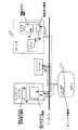
以下、添付図面を参照し、本発明の実施形態を詳細に説明する。図1は、本発明の画像処理装置の実施形態の構成を示すブロック図である。図1に示すように、データバスを介して、HDD10、RAM20(PC内)、CPU30(PC内) 、プリンタ40が接続されている。オリジナル画像のプリントアウトに際し、PCのCPU30はプリンタ40のCPU50とデータパスを介して通信を行い、予め定められているプリンタ40の性能に応じた画質モード(または圧縮率)に応じて画質レベル(圧縮率)を決定する。画像データは決定された画質レベル(圧縮率)に応じてPCにて圧縮され、圧縮後のデータがプリンタ40に送信される。プリンタ40への送信データ量が低減されるため、送信時間が短縮され、圧縮・伸張に要する時間を加味しても、高速なプリントが可能になる。ここで、PCとはパーソナルコンピュータを言う。
【0028】
次に、画像処理装置の動作について説明する。まず、(1)、HDD10上に記録されたオリジナル画像は、CPU30からの命令によってRAM20上に読み込まれる。(2)、CPU30は、RAM20上の画像を読み込み、圧縮を行う。(3)、CPU30は、圧縮後のデータをRAM20上の別の領域に書き込む。(4)、CPU30からの命令によって、圧縮後のデータがプリンタ40内のRAM60上に記録される。(5)、プリンタ40内のCPU50は、圧縮後のデータを読み込み、復号値を得、画像の伸張を行う。(6)、CPU50は、伸張後のデータをRAM60上に書き込む。(7)、その後プリンタ40は、伸張されたデータを所定の手順[変倍がかかる]でプリントアウトする。ここで、括弧でかこまれた数字は図1における動作の順番を示している。
【0029】
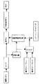
図2は、本発明の画像処理装置の第一実施形態の構成を示すブロック図である。図2を参照し、第一実施形態について説明する。ここで、画像データはRGB原色信号や輝度及び2種類の色差信号などで構成されている。
【0030】
まず、画像データは予め設定された複数のブロックからなるブロックに分割し、そのブロックデータに対して直交変換を行う。
【0031】
次に、直交変換された画像データは量子化器に入力される。ここで、直交変換としては、離散コサイン変換(DCT)が一般的であるが、DWTやアダマール変換等他の変換を用いて良い。
【0032】
次に、初期設定量子化ステップ幅を記憶してある量子化テーブルと画質モードによって設定されたスケーリングファクタ値とを乗算し、その乗算した量子化テーブルに制限値を用い、暫定量子化ステップ幅を求める。そして、変換された係数を求められた量子化ステップ幅によって除算することで、量子化を行う。
【0033】
ここで、スケーリングファクタ値を計算するために、画像データを2回スキャンする場合もある。第1回目のスキャンでは、仮の符号量を算出し、その符号量に応じたスケーリングファクタ値を計算し、第2回目のスキャンでは算出されたスケーリングファクタ値を用いて実際の符号化を行うという方法もある。
【0034】
最後に量子化変換係数をランレングスやハフマン符号等の可変長符号化方法または、固定長符号化方法により、可変長データまたは固定長データに変換し、量子化変換係数値に対応する可変長符号語または固定長符号語を圧縮データとして出力する。
【0035】
図3は、本発明の画像処理装置の第二実施形態の構成を示すブロック図である。図3を参照し、第二実施形態について説明する。画像データはRGB原色信号や輝度及び2種類の色差信号などで構成されている。
【0036】
まず、画像データは予め設定された複数のブロックからなるブロックに分割し、そのブロックデータに対して直交変換を行う。
【0037】
次に、公知にあるように直交変換された画像データを用いて像域分離し、それぞれの領域ごとに設定された量子化テーブルを選択する。そして、画像データは量子化器に入力される。この公知の技術一例として、特開平9−27904号公報に記載の「画像処理方法及びその装置」がある。
【0038】
ここで、直交変換としては、離散コサイン変換(DCT)が一般的であるが、他の変換を用いて良い。また、像域分離は、ブロックデータを用いることによって領域を判定してもよい。
【0039】
次に初期設定量子化ステップ幅を記憶してある量子化テーブルと画質モードによって設定されたスケーリングファクタ値とを乗算し、その乗算した量子化テーブルに領域を判定して得られた制限値を用い、暫定量子化ステップ幅を求める。そして、変換された係数を求められた量子化ステップ幅によって除算することで、量子化を行う。
【0040】
最後に量子化変換係数をランレングスやハフマン符号等の可変長符号化方法または、固定長符号化方法により、可変長データまたは固定長データに変換し、量子化変換係数値に対応する可変長符号語または固定長符号語を圧縮データとして出力する。
【0041】
図4は、本発明の画像処理装置の第三実施形態の構成を示すブロック図である。図4を参照し、第三実施形態について説明する。画像データはRGB原色信号や輝度及び2種類の色差信号などで構成されている。
【0042】
まず、画像データは予め設定された複数のブロックからなるブロックに分割し、そのブロックデータに対して直交変換を行う。ここで、直交変換としては、離散コサイン変換(DCT)が一般的であるが、他の変換を用いて良い。
【0043】
また、公知にあるように各領域の重要度を指定する選択領域情報を使用者が外部から自由に選択することによって、重要度の高い領域と重要度の低い領域に領域指定する。この公知の技術一例として、特開平6−164941号公報の「画像データ符号化方法及び装置」がある。
そして、それぞれの領域ごとに予め設定された量子化テーブルを選択する。
【0044】
次に初期設定量子化ステップ幅を記憶してある量子化テーブルと画質モードによって設定されたスケーリングファクタ値とを乗算し、その乗算した量子化テーブルに領域を判定して得られた制限値を用い、暫定量子化ステップ幅を求める。そして、変換された係数を求められた量子化ステップ幅によって除算することで、量子化を行う。
【0045】
最後に量子化変換係数をランレングスやハフマン符号等の可変長符号化方法または、固定長符号化方法により、可変長データまたは固定長データに変換し、量子化変換係数値に対応する可変長符号語または固定長符号語を圧縮データとして出力する。
【0046】
図18は、本発明の画像処理装置の第一実施形態における符号化の動作を示すフローチャートである。図18を参照し、本発明の画像処理装置の第一実施形態における動作を説明する。画像データをどのモードで圧縮するかを予め設定されたモード(例えば、低画質・標準画質・高画質など)より選択する。これらのモードは、PC画面上のメニュー等によりユーザに選択されたりプリンタの性能に応じて設定される。そして、画像データを選択したモードとして符号化する際、画像データは所定のブロック単位でDCT変換する。そして、その変換されたデータより予め設定された異なる量子化テーブルを用いて量子化する。
【0047】
まず、画像データが輝度Yコンポーネントと色差Cb、Crコンポーネントで構成されている場合、それぞれのコンポーネントに対して、8×8画素ごとにブロック分割し(ステップS1801)、分割された8×8画素ブロックごとにDCT変換を行う(ステップS1802)。
【0048】
次に、変換したデータをどういう画質モードで符号化するかによって、予め設定された量子化テーブルを選択する。すなわち、量子化テーブルにスケーリングファクタを乗じ、低周波数領域に下限値を設定した量子化テーブルを用いて量子化する(ステップS1803)。
【0049】
ここで、例えば、図5、6にあるような輝度Yコンポーネントと色差Cb、Crコンポーネントの量子化テーブルに初期設定し、スケーリングファクタ値を高画質モード(低圧縮)で符号化する場合は1/2 、低画質モード(高圧縮)で符号化する場合は1/1.5と設定したとする。なお、スケーリングファクタ値を出力器の性能が良い場合は1/2 、出力器の性能が悪い場合は1/1.5のように、目標とする圧縮によらず、出力器の性能に応じた設定も可能である。
【0050】
さて、高画質モードの輝度Yコンポーネントと色差Cb、Crコンポーネントの量子化テーブルとスケーリングファクタ値を乗じた暫定量子化テーブルはそれぞれ図7、8のようになる。また、低画質モードの輝度Yコンポーネントと色差Cb、Crコンポーネントの量子化テーブルとスケーリングファクタ値を乗じた暫定量子化テーブルはそれぞれ図9、10のようになる。
【0051】
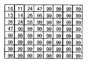
また、周波数成分を例えば図11と図12に示すような2つのグループ(図11は低周波数成分よりと図12は高周波数成分より)に分割し、高画質モードには色差Cb、Crコンポーネントの図8に示した周波数成分に下限値を設定する。例えば、色差Cb、Crに下限値9と設定した場合、暫定量子化テーブルは図13のようになる。
【0052】
よって、高画質モードであると輝度Yは図7、色差Cb、Crは図13、低画質モードであると輝度Yは図9、色差Cb、Crは図10の量子化テーブルに基づいて量子化を行うことにする。量子化は変換されたデータを量子化テーブルの係数によって除算することによって実現される。
【0053】
最後に量子化変換係数をブロック単位でランレングスやハフマン符号等の可変長符号化方法または、固定長符号化方法により、可変長データまたは固定長データに変換し(ステップS1804)、全画面終了(ステップS1805)した場合に、量子化変換係数値に対応する可変長符号語または固定長符号語を圧縮データとして出力する。
【0054】
図19は、本発明の画像処理装置の第二実施形態における文字領域と写真領域のような異なる画像領域の種類によって領域用の下限値を設定し符号化する動作を示すフローチャートである。図19を参照し、本発明の画像処理装置の第二実施形態における動作を説明する。本実施形態では、画像データを高画質(低圧縮)モードとして符号化する。その際、画像データは所定のブロック単位でDCT変換し、その変換されたデータより像域分離を行い、領域ごとに予め設定された異なる量子化テーブルを用いて量子化する。
【0055】
まず、画像データが輝度Yコンポーネントと色差Cb、Crコンポーネントで構成されている場合、それぞれのコンポーネントに対して、8×8画素ごとブロックに分割し(ステップS1901)、分割された8×8画素ブロックごとにDCT変換を行う(ステップS1902)。
【0056】
次に、変換されたデータによって、公知である文字領域と写真領域に像域分離する。この公知の技術一例として、先に述べた特開平9−27904号公報に記載の「画像処理方法及びその装置」がある。そして、それぞれの領域ごとに予め設定された量子化テーブルを選択する。
【0057】
ここで、例えば、図5、6にあるように輝度Yコンポーネントと色差Cb、Crコンポーネントの量子化テーブルを初期設定したとする。また、画像劣化の目立ちやすい文字領域は低めに圧縮し、画像劣化の目立ちにくい写真領域は高めに圧縮するため、スケーリングファクタ値を文字領域の場合は1/2、写真領域の場合は1/1.5と設定したとする。
【0058】
その場合、文字領域の輝度Yコンポーネントと色差Cb、Crコンポーネントの量子化テーブルとスケーリングファクタ値を乗じた暫定量子化テーブルはそれぞれ図7、8のようになる。また、写真領域の輝度Yコンポーネントと色差Cb、Crコンポーネントの量子化テーブルとスケーリングファクタ値を乗じた暫定量子化テーブルはそれぞれ図9、10のようになる。
【0059】
そして、周波数成分を図11と図12に示すような2つのグループ(図11は低周波数成分グループと図12は高周波数成分グループ)に分割し、色差Cb、Crコンポーネントの周波数成分にのみ下限値を設定する。さらに文字領域と写真領域のような異なる画像領域の種類によって(ステップS1903)、それぞれ異なる下限値が設定される(ステップS1904およびS1905)。
【0060】
これは、文字領域は低く圧縮、写真領域は高く圧縮することによって、文字領域は低周波数成分の情報量がかなり大きくなるためである。
【0061】
例えば、文字領域の色差Cb、Crコンポーネントに用いる下限値には9、写真領域の色差Cb、Crコンポーネントに用いる下限値には8のように、用いる下限値に文字領域より写真領域のほうを大きく予め設定したとする。その場合、下限値を設定したそれぞれの暫定テーブルは図14と図15のようになる。
【0062】
よって、文字領域であると輝度Yは図7、色差Cb、Crは図14、写真領域であると輝度Yは図9、色差Cb、Crは図15の量子化テーブルに基づいて量子化を行うことにする(ステップS1906)。量子化は変換されたデータを量子化テーブルの係数によって除算することによって実現される。
【0063】
最後に量子化変換係数をブロック単位でランレングスやハフマン符号等の可変長符号化方法または、固定長符号化方法により、可変長データまたは固定長データに変換し(ステップS1907)、全画面終了(ステップS1908)した場合に、量子化変換係数値に対応する可変長符号語または固定長符号語を圧縮データとして出力する。
【0064】
図20は、本発明の画像処理装置の第三実施形態における領域指定をおこない符号化する動作を示すフローチャートである。図20を参照し、本発明の画像処理装置の第三実施形態における動作を説明する。本実施形態では、画像データを高画質(低圧縮)モードとして符号化する。その際、画像データは所定のブロック単位でDCT変換し、変換されたデータを、使用者が外部より領域指定し、その領域ごとに予め設定された異なる量子化テーブルを用いて量子化する。
【0065】
まず、画像データが輝度Yコンポーネントと色差Cb、Crコンポーネントで構成されている場合、それぞれのコンポーネントに対して、8×8画素ごとブロックに分割し(ステップS2001)、分割された8×8画素ブロックごとにDCT変換を行う(ステップS2002)。
【0066】
また、公知にあるように、使用者は外部から領域の重要度を重要度の高い領域と重要度の低い領域に領域指定する(ステップS2003)。この公知の技術一例として、先に述べた特開平6−164941号公報に記載の「画像データ符号化方法及び装置」がある。そして、それぞれの領域ごとに予め設定された量子化テーブルを選択する。
【0067】
ここで、例えば、図5、6にあるように輝度Yコンポーネントと色差Cb、Crコンポーネントの量子化テーブルを初期設定したとする。また、重要度の高い領域は低圧縮率にし、重要度の低い領域は高圧縮率にするため、低圧縮率のときは量子化ステップ幅を小さくし、高圧縮率のときは量子化ステップ幅を大きくする。例えば、スケーリングファクタ値を重要度の高い領域を符号化する場合は1/2、重要度の低い領域を符号化する場合は1/1.5と設定したとする。
【0068】
その場合、重要度の高い領域の輝度Yコンポーネントと色差Cb、Crコンポーネントの量子化テーブルとスケーリングファクタ値を乗じた暫定量子化テーブルはそれぞれ図7、8のようになる。また、重要度の低い領域の輝度Yコンポーネントと色差Cb、Crコンポーネントの量子化テーブルとスケーリングファクタ値を乗じた暫定量子化テーブルはそれぞれ図9、10のようになる。
【0069】
そして、周波数成分を例えば図11と図12に示すような2つのグループ(図11は低周波数成分よりと図12は高周波数成分より)に分割し、色差Cb、Crコンポーネントの周波数成分に下限値を設定する。さらに重要度の高い領域と重要度の低い領域のような異なる重要度の領域に応じて、それぞれ異なる下限値を設定される(ステップS2004およびS2005)。
【0070】
これは、重要度の高い領域は低圧縮率とし、重要度の低い領域は高圧縮率とするため、重要度の高い領域のほうが低周波数成分の情報量が大きくなるためである。
【0071】
例えば、重要度の高い領域の色差Cb、Crコンポーネントに用いる下限値には9、重要度の低い領域の色差Cb、Crコンポーネントに用いる下限値には8のように、用いる下限値は重要度の高い領域より重要度の低い領域のほうを大きく設定したとする。その場合、下限値を設定したそれぞれの暫定テーブルは図16と図17のようになる。
【0072】
よって、重要度の高い領域であると輝度Yは図7、色差Cb、Crは図16、重要度の低い領域であると輝度Yは図9、色差Cb、Crは図17の量子化テーブルに基づいて量子化を行う(ステップS2006)。量子化は変換されたデータを量子化テーブルの係数によって除算することによって実現される。
【0073】
最後に量子化変換係数をブロック単位でランレングスやハフマン符号等の可変長符号化方法または、固定長符号化方法により、可変長データまたは固定長データに変換し(ステップS2007)、全画面終了(ステップS2008)した場合に、量子化変換係数値に対応する可変長符号語または固定長符号語を圧縮データとして出力する。
【0074】
以上、説明したように、本発明は、画像データを圧縮符号化する画像処理装置であって、周波数変換を行う変換手段と、量子化処理を行う量子化手段と、量子化ステップを変更する変更手段と、量子化ステップ幅に制限値を設定する制限値設定手段とを備えている。ここで、制限値を設定することで、画質と圧縮を両立させることができる。
【0075】
一般に、符号化できる符号量が同じであると、高周波成分の情報は、より破棄の対象とされ(より量子化ステップ幅を荒くする)、低周波数成分の情報を残す対象(より量子化ステップ幅を細かくする)とする。これは、人間の視覚はローパスフィルタであるため、低周波数成分の情報は大きく画質に寄与するからである。
【0076】
しかし、知覚できる範囲を越えてしまうと、多くの低周波数成分の情報を残したとしても、ほとんど画質に寄与しなくなるということがある。さらに、DCT変換等の直交変換を行った場合、多くの画像において低周波数成分に数値が集中し、高周波数成分には小さな値が出現するため、低周波数成分の量子化ステップ幅を小さくするとそれだけ圧縮効率が低くなってしまうという問題が生じる。そのため、符号化する際、人間の知覚できない画質レベルでは、ある程度低周波数成分の量子化ステップ幅を抑制することで、最適な量子化ステップ幅を得ることができる。
【0077】
よって、本発明において、制限値は下限値であるとしている。下限値を用いることで、量子化ステップ幅を制御でき、知覚できない画質レベルでの圧縮効率を高めることを目的とする。
【0078】
以上で述べている「人間の知覚できない範囲」とはどういった場合であるかが問題となる。例えば、画質を客観評価するための評価指数として例えばPSNRがあり、一般にPSNR値で約40dBまでが人間の画質劣化の知覚できる範囲とされていて、それ以上のPSNR値になるとほとんど知覚できなくなる。
【0079】
一方、各々の出力機には画質レベルがあり、高画質で出力する出力機の場合、画質劣化の知覚できない範囲となる。そのため、符号化する際、出力機の性能に応じ、下限値を設定することで、画質を維持しつつ、圧縮効率を高めることができる。
【0080】
よって、本発明において、画像データを出力する出力機の性能に応じて前記下限値を変化させている。また、出力機の性能に応じることで、最適な量子化ステップ幅を得ることができ、画質を維持しつつ、圧縮効率を高めることができる。
【0081】
また、他にも、目標とする圧縮率がかなり低くなった場合も、ほとんど画質劣化の知覚できない範囲となる。そのため、符号化する際、目標とする圧縮率に応じ、下限値を設定することで、最適な量子化ステップ幅を得ることができ、画質を維持しつつ、圧縮効率を高めることができる。
【0082】
よって、本発明は、目標とする圧縮率に応じて前記下限値を変化させている。目標とする圧縮率に応じることで、最適な量子化ステップ幅を得ることができ、画質を維持しつつ、圧縮効率を高めることを目的とする。
【0083】
人間の視覚特性によると、低周波数のものほど量子化ステップ幅を小さくする。そのため、それぞれの周波数成分の特性に対して、最適な量子化ステップ幅で量子化するには、周波数成分ごとに異なる量子化ステップ幅を用いる。
【0084】
よって、本発明は、周波数変換された画像データの係数である周波数変換係数ごとに異なる前記下限値を設定している。また、周波数の特性に合わせて下限値を用いることで、より画質を維持しつつ、圧縮効率を高めることができる。
【0085】
波数成分に制限値を設定する場合、同じような周波数成分ごとグループ化し、そのグループの周波数成分の特性に合った制限値を設定するほうが制御しやすく、構成を簡略化することができる。
【0086】
よって、本発明は、前記周波数変換係数を複数のグループに分けている。複数のグループに分けることで、制御しやすく、構成を簡略化することができる。
【0087】
画像が複数のコンポ−ネント(R、G、Bの3コンポ−ネントや、輝度Y、色差Cb、色差Crの3コンポ−ネント等)からなる場合、上記視覚特性は、コンポ−ネント毎に異なることが知られている。例えば、色差Cb、Crコンポーネントは輝度Yコンポーネントに比べて、人間の目に知覚されにくい。そのため、一般的に色差Cb、Crコンポーネントは輝度Yコンポーネントに比べて、量子化ステップ幅を粗くする。
【0088】
例えば、符号化する際、高画質モードのような目標とする圧縮率が低い場合は低画質モードのような目標とする圧縮率が高い場合に比べて、色差コンポーネントの量子化ステップ幅を細かくする。しかし、色差コンポーネントは知覚されくいため、符号化できる符号量が増えたとしても画質にはそれほど寄与しないのにもかかわらず、圧縮効率は悪くなる。
【0089】
ここで、輝度Yコンポーネント、色差Cbコンポーネント、色差Crコンポーネントとは、RGBの3コンポ−ネントを下記式で変換して得られる輝度と色差のコンポ−ネントのことであり、JPEGで広く使用されている色変換である。
輝度Yコンポーネント = 0.29R + 0.587G + 0.114B
色差Cbコンポーネント = 0.5R−0.4187G−0.01813B
色差Crコンポーネント = −0.1687R−0.3313G+0.5B
【0090】
よって、本発明は、コンポーネントごとに制限値を設定している。コンポーネントの特性を考慮することにより、より画質を維持しつつ圧縮効率を高めることができる。
【0091】
1画面中に異なる性質を持った画像または必要性の異なる画像が混在する場合がある。混在画像を対象とする場合、それぞれの画像の性質または必要性に合った量子化ステップ幅を用いて、量子化を行う必要がある。そのため、所定領域内の画像を識別し、画像の性質や必要性によって、量子化ステップ幅を小さくして高画質になるようにしたり、量子化ステップ幅を大きくしたりする。
【0092】
よって、本発明は、所定領域の画像の性質を判定する判定手段を備え、この判定手段により判定された結果に応じて下限値を設定している。また、領域の性質を考慮に入れた量子化ステップ幅を用いることで、より画質を維持することができる。
【0093】
例えば、従来では1画面中に重要度の高い領域から低い領域までが混在している場合がある。このような画像を対象とする場合、重要度の高い領域ほど、より高画質にしたいという要求がある。重要な領域の量子化ステップ幅を小さく、重要でない領域の量子化ステップ幅を大きくする。すなわち、重要度が高い領域ほど量子化ステップ幅を小さくしていた。
【0094】
しかし、量子化ステップ幅をあまりに小さくすることによって、低周波数領域の情報が多くなりすぎ、圧縮効率が悪くなるという問題が生じる。そのため、重要度が高い領域のように量子化ステップ幅を小さくするような領域は、改善する必要がある。
【0095】
よって、本発明は、判定手段が画像の重要度を判定している。また、領域の重要度の高い領域で画質を改善することができる。
【0096】
また、例えば、1画面中に文字や線画等領域や写真領域または、自然画像領域やコンピュータグラフィックス領域が混在している場合がある。このような画像を対象とする場合、画質劣化が目立ちやすい領域の画質を良くしたいという要求がある。
【0097】
そのため、入力画像の種類によって、量子化ステップ幅を異ならせる必要がある。例えば、画質劣化が比較的目立ちにくい写真領域の量子化ステップ幅を大きく、画質劣化が比較的目立ちやすい文字や線画領域の量子化ステップ幅を小さくする。同様に、画質劣化が比較的目立ちにくい自然画像領域の量子化ステップ幅を大きくし、画質劣化が比較的目立ちやすいコンピュータグラフィックス領域の量子化を小さくするということが知られている。
【0098】
しかし、量子化ステップ幅をあまりに小さくすることによって、低周波数領域の情報が多くなりすぎ、圧縮効率が悪くなるという問題が生じる。
【0099】
よって、本発明は、この判定手段が入力画像の種類を判定している。また、入力画像の種類に応じた量子化ステップ幅を用いることで、より画質を維持することができる。
【0100】
また、本発明は、上記、説明した内容を 実行する画像処理方法を提案している。制限値を設定することで、画質と圧縮を両立させることができる。
【0101】
また、上記画像処理方法は、プログラムによって実行することができる。
【0102】
さらに、上記プログラムはコンピュータが読み取り可能な情報記録媒体に記録することができる。
【0103】
本発明の実施形態について、上記のように詳細に説明したが、上記の実施形態は本発明の好適な実施の例であり、これに限定されるものではなく、本発明の要旨を逸脱しない範囲において種々変形して実施することが可能である。
【0104】
【発明の効果】
以上説明したように、本発明の画像処理装置の実施形態によれば、制限値を設定することで、画質と圧縮を両立させることができる。
【0105】
また、本発明の画像処理装置の実施形態によれば、下限値を用いることで、量子化ステップ幅を制御でき、知覚できない画質レベルでの圧縮効率を高めることができる。
【0106】
また、本発明の画像処理装置の実施形態によれば、出力機の性能に応じることで、最適な量子化ステップ幅を得ることができ、画質を維持しつつ、圧縮効率を高めることができる。
【0107】
また、本発明の画像処理装置の実施形態によれば、目標とする圧縮率に応じることで、最適な量子化ステップ幅を得ることができ、画質を維持しつつ、圧縮効率を高めることができる。
【0108】
また、本発明の画像処理装置の実施形態によれば、周波数の特性に合わせて下限値を用いることで、より画質を維持しつつ、圧縮効率を高めることができる。
【0109】
また、本発明の画像処理装置の実施形態によれば、複数のグループに分けることで、制御しやすく、構成を簡略化することができる。
【0110】
また、本発明の画像処理装置の実施形態によれば、複数グループの一部にのみ設定することで、制御しやすく、構成を簡略化することができる
【0111】
また、本発明の画像処理装置の実施形態によれば、コンポーネントの特性を考慮することにより、より画質を維持しつつ圧縮効率を高めることができる。
【0112】
また、本発明の画像処理装置の実施形態によれば、色差コンポーネントにのみ用いることで、より画質を維持しつつ圧縮効率を高めることができる。
【0113】
また、本発明の画像処理装置の実施形態によれば、領域の性質を考慮に入れた量子化ステップ幅を用いることで、より画質を維持することができる。
【0114】
また、本発明の画像処理装置の実施形態によれば、領域の重要度の高い領域で画質を改善することができる。
【0115】
また、本発明の画像処理装置の実施形態によれば、入力画像の種類に応じた量子化ステップ幅を用いることで、より画質を維持することができる。
【0116】
また、本発明の画像処理方法の実施形態によれば、制限値を設定することで、画質と圧縮を両立させることができる。
【0117】
また、本発明の実施形態によれば、画像処理方法を記録したコンピュータが読み取り可能な情報記録媒体においては、上記画像処理装置の各処理によって、画質を維持しつつ圧縮効率を高めることを可能にするシステムを提供することができる。
【0118】
また、本発明の実施形態によれば、画像処理方法を記録したコンピュータが読み取り可能な情報記録媒体のプログラムにおいては、上記画像処理装置の各処理によって、画質を維持しつつ圧縮効率を高めることを可能にするシステムを提供することができる。
【図面の簡単な説明】
【図1】本発明の画像処理装置の実施形態の構成を示すブロック図である。
【図2】本発明の画像処理装置の第一実施形態の構成を示すブロック図である。
【図3】本発明の画像処理装置の第二実施形態の構成を示すブロック図である。
【図4】本発明の画像処理装置の第三実施形態の構成を示すブロック図である。
【図5】本発明の画像処理装置において使用する輝度Yコンポーネントの量子化テーブルである。
【図6】本発明の画像処理装置において使用する色差Cb、Cr成分コンポーネントの量子化テーブルである。
【図7】本発明の画像処理装置において使用する低圧縮率領域における輝度Yコンポーネントの量子化テーブルである。
【図8】本発明の画像処理装置において使用する低圧縮率領域における色差Cb、Cr成分コンポーネントの量子化テーブルである。
【図9】本発明の画像処理装置において使用する高圧縮率領域における輝度Yコンポーネントの量子化テーブルである。
【図10】本発明の画像処理装置において使用する高圧縮率領域における色差Cb、Cr成分コンポーネントの量子化テーブルである。
【図11】本発明の画像処理装置における周波数成分を低周波数成分よりに周波数成分を分割した周波数成分分割図である。
【図12】本発明の画像処理装置における周波数成分を高周波数成分よりに周波数成分を分割した周波数成分分割図である。
【図13】本発明の画像処理装置において使用する下限値を設定した色差Cb、Cr成分コンポーネントの量子化テーブルである。
【図14】本発明の画像処理装置において使用する文字領域における下限値を設定した色差Cb、Cr成分コンポーネントの量子化テーブルである。
【図15】本発明の画像処理装置において使用する写真領域における下限値を設定した色差Cb、Cr成分コンポーネントの量子化テーブルである。
【図16】本発明の画像処理装置において使用する重要度の高い領域における下限値を設定した色差Cb、Cr成分コンポーネントの量子化テーブルである。
【図17】本発明の画像処理装置において使用する重要度の低い領域における下限値を設定した色差Cb、Cr成分コンポーネントの量子化テーブルである。
【図18】本発明の画像処理装置の第一実施形態における符号化の動作を示すフローチャートである。
【図19】本発明の画像処理装置の第二実施形態における文字領域と写真領域のような異なる画像領域の種類によって領域用の下限値を設定し符号化する動作を示すフローチャートである。
【図20】本発明の画像処理装置の第三実施形態における領域指定をおこない符号化する動作を示すフローチャートである。
【符号の説明】
10 HDD
20 RAM(PC内)
30 CPU(PC内)
40 プリンタ
50 CPU(プリンタ内)
60 RAM(プリンタ内)[0001]
BACKGROUND OF THE INVENTION
The present invention relates to an application program, a device driver such as a printer driver, an image processing apparatus that performs compression encoding of color image data in a device that handles color images, an image processing method thereof, and a recording medium on which the image processing method is recorded.
[0002]
[Prior art]
Conventionally, in the image encoding device described in
[0003]
[Patent Document 1]
JP-A-10-112860
[0004]
Conventionally, the commonly used JPEG baseline system is image coding using orthogonal transform for a color image, a zigzag scan from the low frequency component side, and a quantization step by multiplying a quantization table by a scaling factor value The procedure is such that linear quantization is performed using the value, and the quantized value is encoded sequentially from the DC component.
[0005]
In the case of a color image, the quantization table used for the above quantization can be switched for each component to use an appropriate quantization table. This quantization table can be changed by changing each coefficient itself in the quantization table or by changing a scaling factor value for performing quantization weighting, thereby changing the compression ratio. .
[0006]
Conventionally, there is a method of simultaneously satisfying both the improvement of the compression efficiency and the reproduction of high image quality in all image quality modes by having a plurality of quantization tables according to the compression rate. However, this method has a problem that a large memory capacity is required to hold the quantization table.
[0007]
Therefore, there is a need for a method that satisfies both the improvement of compression efficiency and the reproduction of high image quality by changing the scaling factor value using one of the initially set quantization tables or two of luminance and color difference. The
[0008]
In general, in the quantization table, a small value is set for the low frequency component, considering that the human visual characteristics are sensitive to the low frequency component but insensitive to the high frequency component. Is set to a large value.
[0009]
The scaling factor value is initially set according to the image quality mode (for example, low image quality, standard image quality, high image quality, etc.), or is changed based on the code amount by first scanning the image data.
[0010]
However, with a single quantization table, it is not possible to simultaneously satisfy both the improvement of the compression efficiency and the reproduction of high image quality in all image quality modes only by changing the scaling factor value.
[0011]
Therefore, when the image quality is set low (the compression rate is high), the image quality is excessively deteriorated. When the image quality is set high (the compression rate is low), the compression efficiency is poor.
[0012]
Therefore, in the image encoding device described in
[0013]
There are many methods for suppressing excessive image quality degradation caused by high compression, such as the method in the image encoding device described in
[0014]
[Problems to be solved by the invention]
The present invention has been made in view of the above problems, and an image processing apparatus capable of increasing compression efficiency while maintaining image quality by using an optimal quantization step width even when high image quality is set. Another object of the present invention is to provide an image processing method and a recording medium on which the image processing method is recorded.
[0015]
[Means for Solving the Problems]
In order to achieve the above object, the invention according to claim 1A quantization table storing preset quantization step widths, a setting unit for setting an image quality mode, an orthogonal transform unit for performing orthogonal transform on image data composed of a luminance component and a color difference component, and orthogonal by an orthogonal transform unit Based on the image area separation means that performs image area separation processing on the converted data into character area and photo area, and the quantization table based on the quantization table and the scaling factor value set by the image quality mode, according to the image area separation result Limit value setting means for setting the quantization step width using the limit value set only for the frequency component of the color difference component, and orthogonal transform by the orthogonal transform means based on the quantization step width set by the limit value setting means An image processing apparatus having a quantization means for quantizing the quantized data and an encoding means for encoding the quantized image data, wherein the color difference component of the character area Lower limit, the image processing apparatus and greater than the lower limit value used for the chrominance components of the photographic area usedIt is about.
[0016]
Claim2The described invention is claimed.1In the described invention,SystemThe limit value setting means isstraightA different limit value is set for each conversion coefficient that is a coefficient of image data orthogonally converted by the alternating conversion means.
[0017]
Claim3The described invention is claimed.1In the described invention,SystemThe limit value setting means isstraightThe coefficients of the image data orthogonally transformed by the alternating transform means are grouped for each identical frequency component, and a limit value is set according to the characteristics of the frequency component in the group.
[0018]
Claim4The described invention is claimed.1In the described invention,PictureImage data consists of a plurality of components.SystemIt is characterized by setting a limit value.
[0019]
Claim5The described invention is claimed.4In the invention described inDoubleThe number component consists of luminance and chrominance components,colorTo the difference componentSystemIt is characterized by setting a limit value.
[0020]
Claim6The described inventionA storage process for storing a quantization step width preset for each region in the quantization table, a setting process for setting an image quality mode, and an orthogonal transform process for performing orthogonal transform on image data composed of a luminance component and a color difference component And an image area separation process for performing image area separation processing on the data orthogonally transformed in the orthogonal transformation process into a character area and a photographic area, and a quantization table and a scaling factor value set by an image quality mode. , Image area Based on the limit value setting step that sets the quantization step width using the limit value that is set only for the frequency component of the color difference component according to the separation result, and the orthogonal transformation based on the quantization step width that is set in the limit value setting step An image processing method having a quantization step for quantizing the data orthogonally transformed in the step and an encoding step for encoding the quantized image data, wherein the lower limit value used for the color difference component of the character region is An image processing method characterized by being larger than a lower limit value used for a color difference component of a photographic regionIt is about.
[0021]
Claim7The described invention is claimed.6In the described invention,SystemIn the limit value setting process,straightA different limit value is set for each conversion coefficient which is a coefficient of image data orthogonally converted in the cross conversion process.
[0022]
Claim8The described invention is claimed.6In the described invention,SystemIn the limit value setting process,straightThe coefficients of the image data orthogonally transformed in the alternating transformation process are grouped for each identical frequency component, and a limit value is set according to the characteristics of the frequency component in the group.
[0023]
Claim9The described invention is claimed.6In the described invention,PictureImage data consists of a plurality of components.SystemIt is characterized by setting a limit value.
[0024]
Claim10The described invention is claimed.9In the invention described inDoubleThe number component consists of luminance and chrominance components,colorTo the difference componentSystemIt is characterized by setting a limit value.
[0025]
Claim11The described invention is claimed.6From10A program for executing the image processing method according to any one of the above.
[0026]
Claim12The described invention is claimed.11Described inNoIt is a recording medium that records a program and can be read by a computer.
[0027]
DETAILED DESCRIPTION OF THE INVENTION
Hereinafter, embodiments of the present invention will be described in detail with reference to the accompanying drawings. FIG. 1 is a block diagram showing a configuration of an embodiment of an image processing apparatus of the present invention. As shown in FIG. 1, an
[0028]
Next, the operation of the image processing apparatus will be described. First,(1)The original image recorded on the
[0029]
FIG. 2 is a block diagram showing the configuration of the first embodiment of the image processing apparatus of the present invention. The first embodiment will be described with reference to FIG. Here, the image data is composed of RGB primary color signals, luminance and two types of color difference signals.
[0030]
First, the image data is divided into a plurality of preset blocks, and orthogonal transformation is performed on the block data.
[0031]
Next, the orthogonally transformed image data is input to the quantizer. Here, as the orthogonal transformation, discrete cosine transformation (DCT) is generally used, but other transformations such as DWT and Hadamard transformation may be used.
[0032]
Next, the quantization table storing the initial quantization step width is multiplied by the scaling factor value set according to the image quality mode, and the limit value is used for the multiplied quantization table, and the provisional quantization step width is set. Ask. Then, quantization is performed by dividing the transformed coefficient by the obtained quantization step width.
[0033]
Here, the image data may be scanned twice to calculate the scaling factor value. In the first scan, a provisional code amount is calculated, a scaling factor value corresponding to the code amount is calculated, and in the second scan, actual encoding is performed using the calculated scaling factor value. There is also a method.
[0034]
Finally, the quantized transform coefficient is converted into variable length data or fixed length data by a variable length coding method such as run length or Huffman code or a fixed length coding method, and a variable length code corresponding to the quantized transform coefficient value Word or fixed-length codeword is output as compressed data.
[0035]
FIG. 3 is a block diagram showing the configuration of the second embodiment of the image processing apparatus of the present invention. The second embodiment will be described with reference to FIG. The image data is composed of RGB primary color signals, luminance and two types of color difference signals.
[0036]
First, the image data is divided into a plurality of preset blocks, and orthogonal transformation is performed on the block data.
[0037]
Next, as is well known, image area separation is performed using image data subjected to orthogonal transformation, and a quantization table set for each area is selected. Then, the image data is input to the quantizer. As an example of this known technique, there is an “image processing method and apparatus” described in JP-A-9-27904.
[0038]
Here, as the orthogonal transform, discrete cosine transform (DCT) is generally used, but other transforms may be used. In the image area separation, the area may be determined by using block data.
[0039]
Next, the quantization table storing the initial quantization step width is multiplied by the scaling factor value set according to the image quality mode, and the limit value obtained by determining the region is used for the multiplied quantization table. The provisional quantization step width is obtained. Then, quantization is performed by dividing the transformed coefficient by the obtained quantization step width.
[0040]
Finally, the quantized transform coefficient is converted into variable length data or fixed length data by a variable length coding method such as run length or Huffman code or a fixed length coding method, and a variable length code corresponding to the quantized transform coefficient value Word or fixed-length codeword is output as compressed data.
[0041]
FIG. 4 is a block diagram showing the configuration of the third embodiment of the image processing apparatus of the present invention. A third embodiment will be described with reference to FIG. The image data is composed of RGB primary color signals, luminance and two types of color difference signals.
[0042]
First, the image data is divided into a plurality of preset blocks, and orthogonal transformation is performed on the block data. Here, as the orthogonal transform, discrete cosine transform (DCT) is generally used, but other transforms may be used.
[0043]
Further, as is well known, the user designates the selected area information for designating the importance of each area from the outside, so that the area is designated as a high importance area and a low importance area. As an example of this known technique, there is "Image data encoding method and apparatus" disclosed in Japanese Patent Laid-Open No. 6-164941.
Then, a quantization table set in advance for each region is selected.
[0044]
Next, the quantization table storing the initial quantization step width is multiplied by the scaling factor value set according to the image quality mode, and the limit value obtained by determining the region is used for the multiplied quantization table. The provisional quantization step width is obtained. Then, quantization is performed by dividing the transformed coefficient by the obtained quantization step width.
[0045]
Finally, the quantized transform coefficient is converted into variable length data or fixed length data by a variable length coding method such as run length or Huffman code or a fixed length coding method, and a variable length code corresponding to the quantized transform coefficient value Word or fixed-length codeword is output as compressed data.
[0046]
FIG. 18 is a flowchart showing an encoding operation in the first embodiment of the image processing apparatus of the present invention. The operation in the first embodiment of the image processing apparatus of the present invention will be described with reference to FIG. The mode in which the image data is compressed is selected from preset modes (for example, low image quality, standard image quality, high image quality, etc.). These modes are selected by the user from a menu on the PC screen or set according to the performance of the printer. When the image data is encoded as the selected mode, the image data is DCT-converted in predetermined block units. Then, quantization is performed using a different quantization table set in advance from the converted data.
[0047]
First, when the image data is composed of a luminance Y component and color difference Cb and Cr components, each component is divided into blocks of 8 × 8 pixels (step S1801), and the divided 8 × 8 pixel blocks are divided. DCT conversion is performed every time (step S1802).
[0048]
Next, a preset quantization table is selected depending on in which image quality mode the converted data is encoded. That is, the quantization table is multiplied by the scaling factor, and quantization is performed using the quantization table in which the lower limit value is set in the low frequency region (step S1803).
[0049]
Here, for example, when initializing the quantization table of the luminance Y component and the color differences Cb and Cr components as shown in FIGS. 5 and 6 and encoding the scaling factor value in the high image quality mode (low compression), 1 / 2. Assume that 1 / 1.5 is set when encoding in the low image quality mode (high compression). Note that the scaling factor value depends on the performance of the output device regardless of the target compression, such as 1/2 when the output device performance is good and 1 / 1.5 when the output device performance is poor. Setting is also possible.
[0050]
Now, the quantization table of the luminance Y component in the high image quality mode, the color difference Cb and Cr components, and the provisional quantization table obtained by multiplying the scaling factor values are as shown in FIGS. Also, the quantization table of the luminance Y component, the color difference Cb and Cr components in the low image quality mode, and the provisional quantization table obtained by multiplying the scaling factor values are as shown in FIGS.
[0051]
Further, the frequency components are divided into two groups as shown in FIGS. 11 and 12, for example, FIG. 11 is based on the low frequency components and FIG. 12 is based on the high frequency components. A lower limit value is set for the frequency component shown in FIG. For example, when the
[0052]
Therefore, in the high image quality mode, the luminance Y is based on the quantization table in FIG. 7, the color differences Cb and Cr are in FIG. 13, and in the low image quality mode, the luminance Y is in FIG. 9, and the color differences Cb and Cr are quantized based on the quantization table in FIG. To do. Quantization is realized by dividing the transformed data by the coefficient of the quantization table.
[0053]
Finally, the quantized transform coefficient is converted into variable-length data or fixed-length data by a variable-length encoding method such as run length or Huffman code or a fixed-length encoding method in units of blocks (step S1804), and the entire screen ends ( In step S1805), a variable length codeword or a fixed length codeword corresponding to the quantized transform coefficient value is output as compressed data.
[0054]
FIG. 19 is a flowchart showing an operation of setting and encoding a lower limit value for an area depending on the types of different image areas such as a character area and a photographic area in the second embodiment of the image processing apparatus of the present invention. The operation in the second embodiment of the image processing apparatus of the present invention will be described with reference to FIG. In this embodiment, image data is encoded as a high image quality (low compression) mode. At that time, the image data is subjected to DCT conversion in units of predetermined blocks, image area separation is performed from the converted data, and quantization is performed using different quantization tables set in advance for each area.
[0055]
First, when the image data is composed of a luminance Y component and color difference Cb and Cr components, each component is divided into blocks of 8 × 8 pixels (step S1901), and the divided 8 × 8 pixel blocks are divided. DCT conversion is performed every time (step S1902).
[0056]
Next, the image area is separated into a known character area and photographic area by the converted data. As an example of this known technique, there is an “image processing method and apparatus” described in JP-A-9-27904 described above. Then, a quantization table set in advance for each region is selected.
[0057]
Here, for example, as shown in FIGS. 5 and 6, it is assumed that the quantization table of the luminance Y component and the color differences Cb and Cr components is initialized. In addition, since the character region that is prominent in image degradation is compressed to a low level and the photo region that is not prominent in image degradation is compressed to a high level, the scaling factor value is 1/2 for the character region and 1/1 for the photo region. .5 is set.
[0058]
In that case, the provisional quantization table obtained by multiplying the luminance Y component, the color difference Cb, Cr component quantization table, and the scaling factor value in the character area is as shown in FIGS. Also, the temporary quantization table obtained by multiplying the luminance Y component, the color difference Cb, Cr component quantization table, and the scaling factor value in the photographic area is as shown in FIGS.
[0059]
Then, the frequency component is divided into two groups as shown in FIGS. 11 and 12 (FIG. 11 is a low frequency component group and FIG. 12 is a high frequency component group), and only the lower limit value is applied to the frequency components of the color difference Cb and Cr components. Set. Further, different lower limit values are set according to the types of different image areas such as a character area and a photo area (step S1903) (steps S1904 and S1905).
[0060]
This is because the amount of information of low frequency components in the character region becomes considerably large by compressing the character region low and compressing the photo region high.
[0061]
For example, the lower limit value used for the color difference Cb and Cr component of the character area is 9 and the lower limit value used for the color difference Cb and Cr component of the photo area is 8, and the lower limit value used is larger in the photo area than the character area. It is assumed that it is set in advance. In that case, the provisional tables in which the lower limit value is set are as shown in FIGS.
[0062]
Therefore, luminance Y is quantized based on the quantization table in FIG. 7 for the character area, color differences Cb and Cr are based on the quantization table in FIG. 14, and luminance Y is in FIG. 9 and color differences Cb and Cr are in the photo area in FIG. (Step S1906). Quantization is realized by dividing the transformed data by the coefficient of the quantization table.
[0063]
Finally, the quantized transform coefficient is converted into variable-length data or fixed-length data by a variable-length encoding method such as run length or Huffman code or a fixed-length encoding method in units of blocks (step S1907), and the entire screen ends ( In the case of step S1908), the variable length codeword or fixed length codeword corresponding to the quantized transform coefficient value is output as compressed data.
[0064]
FIG. 20 is a flowchart showing an operation of performing area designation and encoding in the third embodiment of the image processing apparatus of the present invention. The operation in the third embodiment of the image processing apparatus of the present invention will be described with reference to FIG. In this embodiment, image data is encoded as a high image quality (low compression) mode. At this time, the image data is subjected to DCT conversion in a predetermined block unit, and the converted data is designated by the user from the outside, and is quantized using a different quantization table set in advance for each area.
[0065]
First, when the image data is composed of a luminance Y component and color difference Cb and Cr components, each component is divided into blocks of 8 × 8 pixels (step S2001), and the divided 8 × 8 pixel blocks are divided. DCT conversion is performed every time (step S2002).
[0066]
As is well known, the user designates the importance of the area from the outside as a high importance area and a low importance area (step S2003). As an example of this known technique, there is an “image data encoding method and apparatus” described in JP-A-6-164941 described above. Then, a quantization table set in advance for each region is selected.
[0067]
Here, for example, as shown in FIGS. 5 and 6, it is assumed that the quantization table of the luminance Y component and the color differences Cb and Cr components is initialized. Also, because the high importance area has a low compression ratio and the low importance area has a high compression ratio, the quantization step width is reduced when the compression ratio is low, and the quantization step width when the compression ratio is high. Increase For example, it is assumed that the scaling factor value is set to 1/2 when encoding a region with high importance and 1 / 1.5 when encoding a region with low importance.
[0068]
In this case, the provisional quantization tables obtained by multiplying the luminance Y component, the color difference Cb and Cr component quantization tables, and the scaling factor values in the region of high importance are as shown in FIGS. In addition, the provisional quantization tables obtained by multiplying the luminance Y component, the color difference Cb and Cr component quantization tables, and the scaling factor values in the area of low importance are as shown in FIGS.
[0069]
Then, for example, the frequency component is divided into two groups as shown in FIGS. 11 and 12 (FIG. 11 is based on the low frequency component and FIG. 12 is based on the high frequency component), and the color difference Cb and Cr component frequency components have lower limit values. Set. Further, different lower limit values are set according to different importance areas such as a higher importance area and a lower importance area (steps S2004 and S2005).
[0070]
This is because a region with high importance has a low compression rate and a region with low importance has a high compression rate, so that a region with high importance has a larger amount of information of low frequency components.
[0071]
For example, the lower limit value used for the color difference Cb and Cr component in the high importance area is 9 and the lower limit value used for the color difference Cb and Cr component in the low importance area is 8; Assume that the lower importance area is set larger than the higher area. In that case, the provisional tables in which the lower limit value is set are as shown in FIGS.
[0072]
Accordingly, the luminance Y is in the quantization table of FIG. 7, the color differences Cb and Cr are in FIG. 16, and the luminance Y is in FIG. 9 and the color differences Cb and Cr are in the quantization table of FIG. Based on this, quantization is performed (step S2006). Quantization is realized by dividing the transformed data by the coefficient of the quantization table.
[0073]
Finally, the quantized transform coefficient is converted into variable-length data or fixed-length data by a variable-length encoding method such as run length or Huffman code or a fixed-length encoding method in units of blocks (step S2007), and the entire screen ends ( In step S2008), a variable length codeword or a fixed length codeword corresponding to the quantized transform coefficient value is output as compressed data.
[0074]
As described above, the present invention is an image processing apparatus that compresses and encodes image data, and includes a conversion unit that performs frequency conversion, a quantization unit that performs quantization processing, and a change that changes a quantization step. Means and limit value setting means for setting a limit value for the quantization step width. Here, by setting a limit value, both image quality and compression can be achieved.
[0075]
In general, if the amount of code that can be encoded is the same, the information of the high frequency component is more subject to discarding (more roughening the quantization step width), and the target to leave the information of the low frequency component (more quantization step width) ). This is because human vision is a low-pass filter, and information on low-frequency components greatly contributes to image quality.
[0076]
However, if the perceivable range is exceeded, even if a lot of low frequency component information is left, it may hardly contribute to the image quality. Furthermore, when orthogonal transformation such as DCT transformation is performed, numerical values are concentrated on low-frequency components in many images, and small values appear on high-frequency components. There arises a problem that the compression efficiency is lowered. Therefore, at the time of encoding, an optimum quantization step width can be obtained by suppressing the quantization step width of low frequency components to some extent at an image quality level that cannot be perceived by humans.
[0077]
Therefore, in the present invention, the limit value is the lower limit value. By using the lower limit value, it is possible to control the quantization step width and to increase the compression efficiency at an image quality level that cannot be perceived.
[0078]
The question is what is the “range that humans cannot perceive” described above. For example, there is PSNR as an evaluation index for objectively evaluating image quality. Generally, a PSNR value of up to about 40 dB is a perceivable range of human image quality degradation, and a PSNR value higher than that is hardly perceivable.
[0079]
On the other hand, each output device has an image quality level, and in the case of an output device that outputs with high image quality, it is in a range where image quality deterioration cannot be perceived. Therefore, when encoding, the compression efficiency can be improved while maintaining the image quality by setting the lower limit value according to the performance of the output device.
[0080]
Therefore, in the present invention, the lower limit value is changed according to the performance of the output device that outputs the image data. In addition, depending on the performance of the output device, an optimal quantization step width can be obtained, and compression efficiency can be increased while maintaining image quality.
[0081]
In addition, even when the target compression rate is considerably low, it is in a range in which image quality degradation can hardly be perceived. Therefore, when encoding, an optimal quantization step width can be obtained by setting a lower limit value in accordance with a target compression rate, and compression efficiency can be increased while maintaining image quality.
[0082]
Therefore, in the present invention, the lower limit value is changed according to the target compression rate. An object of the present invention is to obtain an optimum quantization step width by responding to a target compression rate, and to improve compression efficiency while maintaining image quality.
[0083]
According to human visual characteristics, the lower the frequency, the smaller the quantization step width. Therefore, in order to quantize the frequency component characteristics with the optimum quantization step width, a different quantization step width is used for each frequency component.
[0084]
Therefore, in the present invention, the lower limit value is set different for each frequency conversion coefficient that is a coefficient of the frequency-converted image data. Further, by using the lower limit value according to the frequency characteristics, it is possible to increase the compression efficiency while maintaining the image quality.
[0085]
When setting a limit value for the wave number component, it is easier to control and to simplify the configuration by grouping together similar frequency components and setting a limit value that matches the characteristics of the frequency components of the group.
[0086]
Therefore, the present invention divides the frequency conversion coefficient into a plurality of groups. By dividing into a plurality of groups, it is easy to control and the configuration can be simplified.
[0087]
When an image is composed of a plurality of components (three components of R, G, and B, three components of luminance Y, color difference Cb, and color difference Cr), the visual characteristics are different for each component. It is known. For example, the color difference Cb and Cr components are less likely to be perceived by the human eye than the luminance Y component. For this reason, the color difference Cb and Cr components generally make the quantization step width coarser than the luminance Y component.
[0088]
For example, when encoding, if the target compression rate is low, such as the high image quality mode, the quantization step width of the color difference component is made finer than when the target compression rate is low, such as in the low image quality mode. . However, since the color difference component is difficult to perceive, even if the amount of codes that can be encoded increases, the compression efficiency is deteriorated even though it does not contribute much to the image quality.
[0089]
Here, the luminance Y component, the color difference Cb component, and the color difference Cr component are components of luminance and color difference obtained by converting the three components of RGB by the following formula, and are widely used in JPEG. Color conversion.
Luminance Y component = 0.29R + 0.587G + 0.114B
Color difference Cb component = 0.5R-0.4187G-0.08113B
Color difference Cr component = -0.1687R-0.3313G + 0.5B
[0090]
Therefore, the present invention sets a limit value for each component. By considering the component characteristics, the compression efficiency can be increased while maintaining the image quality.
[0091]
There are cases where images having different properties or images having different needs are mixed in one screen. When a mixed image is targeted, it is necessary to perform quantization using a quantization step width that matches the properties or needs of each image. For this reason, an image in a predetermined area is identified, and the quantization step width is reduced to achieve high image quality or the quantization step width is increased depending on the nature and necessity of the image.
[0092]
Therefore, the present invention includes determination means for determining the nature of the image in the predetermined area, and sets a lower limit value according to the result determined by the determination means. Further, the image quality can be further maintained by using a quantization step width that takes into account the characteristics of the region.
[0093]
For example, conventionally, there is a case where a region from a high importance to a low region is mixed in one screen. When such an image is targeted, there is a demand for higher image quality in a region of higher importance. Decrease the quantization step width in the important area and increase the quantization step width in the unimportant area. That is, the quantization step width is reduced in the region of higher importance.
[0094]
However, when the quantization step width is made too small, there is a problem that the information in the low frequency region becomes too much and the compression efficiency is deteriorated. Therefore, it is necessary to improve a region where the quantization step width is reduced, such as a region having high importance.
[0095]
Therefore, according to the present invention, the determination unit determines the importance of the image. In addition, the image quality can be improved in a region having a high degree of importance.
[0096]
In addition, for example, there may be a case where a character or line drawing area, a photo area, a natural image area, or a computer graphics area is mixed in one screen. When such an image is a target, there is a demand for improving the image quality in a region where image quality degradation is conspicuous.
[0097]
Therefore, it is necessary to vary the quantization step width depending on the type of input image. For example, the quantization step width of a photographic area where image quality deterioration is relatively unnoticeable is increased, and the quantization step width of a character or line drawing area where image quality deterioration is relatively conspicuous is reduced. Similarly, it is known to increase the quantization step width of a natural image region where image quality degradation is relatively inconspicuous and to reduce the quantization of a computer graphics region where image quality degradation is relatively conspicuous.
[0098]
However, when the quantization step width is made too small, there is a problem that the information in the low frequency region becomes too much and the compression efficiency is deteriorated.
[0099]
Therefore, in the present invention, this determination means determines the type of the input image. Further, the image quality can be maintained more by using the quantization step width corresponding to the type of the input image.
[0100]
The present invention also proposes an image processing method for executing the above-described contents. By setting the limit value, both image quality and compression can be achieved.
[0101]
The image processing method can be executed by a program.
[0102]
Furthermore, the program can be recorded on an information recording medium that can be read by a computer.
[0103]
Although the embodiment of the present invention has been described in detail as described above, the above-described embodiment is a preferred embodiment of the present invention, and is not limited thereto, and does not depart from the gist of the present invention. It is possible to implement with various modifications.
[0104]
【The invention's effect】
As described above, according to the embodiment of the image processing apparatus of the present invention, it is possible to achieve both image quality and compression by setting a limit value.
[0105]
Further, according to the embodiment of the image processing apparatus of the present invention, by using the lower limit value, the quantization step width can be controlled, and the compression efficiency at an image quality level that cannot be perceived can be increased.
[0106]
In addition, according to the embodiment of the image processing apparatus of the present invention, an optimal quantization step width can be obtained according to the performance of the output device, and the compression efficiency can be increased while maintaining the image quality.
[0107]
Further, according to the embodiment of the image processing apparatus of the present invention, an optimal quantization step width can be obtained by responding to a target compression rate, and compression efficiency can be improved while maintaining image quality. .
[0108]
According to the embodiment of the image processing apparatus of the present invention, the compression efficiency can be improved while maintaining the image quality more by using the lower limit value according to the frequency characteristic.
[0109]
Further, according to the embodiment of the image processing apparatus of the present invention, by dividing into a plurality of groups, it is easy to control and the configuration can be simplified.
[0110]
Further, according to the embodiment of the image processing apparatus of the present invention, by setting only a part of a plurality of groups, it is easy to control and the configuration can be simplified.
[0111]
Further, according to the embodiment of the image processing apparatus of the present invention, the compression efficiency can be improved while maintaining the image quality more by considering the component characteristics.
[0112]
Further, according to the embodiment of the image processing apparatus of the present invention, the compression efficiency can be increased while maintaining the image quality by using only the color difference component.
[0113]
Further, according to the embodiment of the image processing apparatus of the present invention, the image quality can be further maintained by using the quantization step width that takes into consideration the nature of the region.
[0114]
Further, according to the embodiment of the image processing apparatus of the present invention, it is possible to improve the image quality in a region having a high degree of importance.
[0115]
Further, according to the embodiment of the image processing apparatus of the present invention, the image quality can be further maintained by using the quantization step width corresponding to the type of the input image.
[0116]
Further, according to the embodiment of the image processing method of the present invention, it is possible to achieve both image quality and compression by setting a limit value.
[0117]
Further, according to the embodiment of the present invention, in a computer-readable information recording medium on which an image processing method is recorded, it is possible to increase compression efficiency while maintaining image quality by each process of the image processing apparatus. System can be provided.
[0118]
Further, according to the embodiment of the present invention, in the computer-readable information recording medium program recording the image processing method, the compression efficiency is improved while maintaining the image quality by each process of the image processing apparatus. A system can be provided that enables it.
[Brief description of the drawings]
FIG. 1 is a block diagram showing a configuration of an embodiment of an image processing apparatus of the present invention.
FIG. 2 is a block diagram showing the configuration of the first embodiment of the image processing apparatus of the present invention.
FIG. 3 is a block diagram showing a configuration of a second embodiment of the image processing apparatus of the present invention.
FIG. 4 is a block diagram showing a configuration of a third embodiment of the image processing apparatus of the present invention.
FIG. 5 is a quantization table of luminance Y components used in the image processing apparatus of the present invention.
FIG. 6 is a quantization table of color difference Cb and Cr component components used in the image processing apparatus of the present invention.
FIG. 7 is a quantization table of luminance Y components in a low compression rate region used in the image processing apparatus of the present invention.
FIG. 8 is a quantization table of color difference Cb and Cr component components in a low compression rate region used in the image processing apparatus of the present invention.
FIG. 9 is a quantization table of luminance Y components in a high compression ratio region used in the image processing apparatus of the present invention.
FIG. 10 is a quantization table of color difference Cb and Cr component components in a high compression ratio region used in the image processing apparatus of the present invention.
FIG. 11 is a frequency component division diagram in which frequency components are divided into low frequency components and low frequency components in the image processing apparatus of the present invention.
FIG. 12 is a frequency component division diagram in which frequency components are divided into higher frequency components than higher frequency components in the image processing apparatus of the present invention.
FIG. 13 is a quantization table of color difference Cb and Cr component components in which lower limit values used in the image processing apparatus of the present invention are set.
FIG. 14 is a quantization table of color difference Cb and Cr component components in which a lower limit value is set in a character area used in the image processing apparatus of the present invention.
FIG. 15 is a quantization table of color difference Cb and Cr component components in which a lower limit value is set in a photographic region used in the image processing apparatus of the present invention.
FIG. 16 is a quantization table of color difference Cb and Cr component components in which lower limit values are set in areas of high importance used in the image processing apparatus of the present invention.
FIG. 17 is a quantization table of color difference Cb and Cr component components in which a lower limit value is set in a low importance area used in the image processing apparatus of the present invention.
FIG. 18 is a flowchart showing an encoding operation in the first embodiment of the image processing apparatus of the present invention;
FIG. 19 is a flowchart showing an operation of setting and encoding a lower limit value for an area according to different types of image areas such as a character area and a photographic area in the second embodiment of the image processing apparatus of the present invention.
FIG. 20 is a flowchart showing an operation of performing region designation and encoding in the third embodiment of the image processing apparatus of the present invention.
[Explanation of symbols]
10 HDD
20 RAM (inside PC)
30 CPU (in PC)
40 Printer
50 CPU (inside printer)
60 RAM (in the printer)
Claims (12)
画質モードを設定する設定手段と、
輝度成分と色差成分とからなる画像データに直交変換を行う直交変換手段と、
前記直交変換手段で直交変換されたデータを文字領域と写真領域とに像域分離処理する像域分離手段と、
前記量子化テーブルと前記画質モードによって設定されたスケーリングファクタ値とに基づき前記量子化テーブルに、前記像域分離結果に応じて色差成分の周波数成分にのみ設定された制限値を用いた量子化ステップ幅を設定する制限値設定手段と、
前記制限値設定手段で設定された量子化ステップ幅に基づき、前記直交変換手段で直交変換されたデータを量子化する量子化手段と、
量子化された画像データを符号化する符号化手段と、を有する画像処理装置であって、
前記文字領域の色差成分に用いる下限値は、前記写真領域の色差成分に用いる下限値よりも大きいことを特徴とする画像処理装置。A quantization table storing pre Me set quantization step width,
Setting means for setting the image quality mode;
Orthogonal transformation means for performing orthogonal transformation on image data composed of a luminance component and a color difference component ;
An image area separating means for image area separation processing orthogonally transformed data by the orthogonal transform means into a character area and a photographic area,
Based on the quantization table and the scaling factor value set according to the image quality mode, a quantization step using a limit value set only in the frequency component of the color difference component in the quantization table according to the image area separation result Limit value setting means for setting the width;
Quantizing means for quantizing the based-out the set quantization step width limit value setting means, orthogonally transformed data by the orthogonal transformation means,
An image processing apparatus having encoding means for encoding quantized image data ,
An image processing apparatus, wherein a lower limit value used for a color difference component of the character area is larger than a lower limit value used for a color difference component of the photograph area .
前記直交変換手段で直交変換された画像データの係数である変換係数毎に異なる制限値を設定することを特徴とする請求項1記載の画像処理装置。The limit value setting means includes:
The image processing apparatus according to claim 1, wherein setting the orthogonally transformed different limit values for each transform coefficient is a coefficient of the image data in the orthogonal transform means.
前記直交変換手段で直交変換された画像データの係数を同一周波数成分毎にグループ化し、当該グループにおける周波数成分の特性に応じた制限値を設定することを特徴とする請求項1記載の画像処理装置。The limit value setting means includes:
Grouping the coefficients of the orthogonal transformed image data in the orthogonal transform unit for each same frequency component, the image processing apparatus according to claim 1, wherein setting the limit value corresponding to a characteristic of the frequency components in the group .
画質モードを設定する設定工程と、
輝度成分と色差成分とからなる画像データに直交変換を行う直交変換工程と、
前記直交変換工程において直交変換されたデータを文字領域と写真領域とに像域分離処理する像域分離工程と、
前記量子化テーブルと前記画質モードによって設定されたスケーリングファクタ値とに基づき前記量子化テーブルに、前記像域分離結果に応じて色差成分の周波数成分にのみ設定された制限値を用いた量子化ステップ幅を設定する制限値設定工程と、
前記制限値設定工程において設定された量子化ステップ幅に基づき、前記直交変換工程で直交変換されたデータを量子化する量子化工程と、
量子化された画像データを符号化する符号化工程と、を有する画像処理方法であって、
前記文字領域の色差成分に用いる下限値は、前記写真領域の色差成分に用いる下限値よりも大きいことを特徴とする画像処理方法。 A storage step of storing a quantization step width preset for each region in the quantization table;
A setting process for setting the image quality mode;
An orthogonal transform process for performing orthogonal transform on image data composed of a luminance component and a color difference component ;
And image separation step of image area separation processing orthogonally transformed data into a character region and a photograph region in said orthogonal transformation step,
Based on the quantization table and the scaling factor value set according to the image quality mode, a quantization step using a limit value set only in the frequency component of the color difference component in the quantization table according to the image area separation result Limit value setting process to set the width;
A quantization step of quantizing the based-out the set quantization step width in the limit value setting step, orthogonally transformed data by the orthogonal transformation step,
A images processing method that have a an encoding step of encoding the image data quantized,
An image processing method, wherein a lower limit value used for a color difference component of the character area is larger than a lower limit value used for a color difference component of the photograph area .
前記直交変換工程で直交変換された画像データの係数である変換係数毎に異なる制限値を設定することを特徴とする請求項6記載の画像処理方法。In the limit value setting step,
The image processing method according to claim 6 , wherein a different limit value is set for each transform coefficient that is a coefficient of image data orthogonally transformed in the orthogonal transform step.
前記直交変換工程で直交変換された画像データの係数を同一周波数成分毎にグループ化し、当該グループにおける周波数成分の特性に応じた制限値を設定することを特徴とする請求項6記載の画像処理方法。In the limit value setting step,
7. The image processing method according to claim 6 , wherein the coefficients of the image data orthogonally transformed in the orthogonal transformation step are grouped for each same frequency component, and a limit value is set according to the characteristic of the frequency component in the group. .
Priority Applications (1)
| Application Number | Priority Date | Filing Date | Title |
|---|---|---|---|
| JP2002276031A JP3989343B2 (en) | 2002-09-20 | 2002-09-20 | Image processing apparatus, image processing method, and recording medium on which image processing method is recorded |
Applications Claiming Priority (1)
| Application Number | Priority Date | Filing Date | Title |
|---|---|---|---|
| JP2002276031A JP3989343B2 (en) | 2002-09-20 | 2002-09-20 | Image processing apparatus, image processing method, and recording medium on which image processing method is recorded |
Publications (3)
| Publication Number | Publication Date |
|---|---|
| JP2004112712A JP2004112712A (en) | 2004-04-08 |
| JP2004112712A5 JP2004112712A5 (en) | 2005-09-15 |
| JP3989343B2 true JP3989343B2 (en) | 2007-10-10 |
Family
ID=32272040
Family Applications (1)
| Application Number | Title | Priority Date | Filing Date |
|---|---|---|---|
| JP2002276031A Expired - Fee Related JP3989343B2 (en) | 2002-09-20 | 2002-09-20 | Image processing apparatus, image processing method, and recording medium on which image processing method is recorded |
Country Status (1)
| Country | Link |
|---|---|
| JP (1) | JP3989343B2 (en) |
Families Citing this family (3)
| Publication number | Priority date | Publication date | Assignee | Title |
|---|---|---|---|---|
| US8213498B2 (en) * | 2007-05-31 | 2012-07-03 | Qualcomm Incorporated | Bitrate reduction techniques for image transcoding |
| JP5267252B2 (en) * | 2009-03-18 | 2013-08-21 | 株式会社リコー | Image encoding device, image encoding method, image encoding recording medium, and image encoding program |
| JP2012178818A (en) * | 2011-01-31 | 2012-09-13 | Panasonic Corp | Video encoder and video encoding method |
-
2002
- 2002-09-20 JP JP2002276031A patent/JP3989343B2/en not_active Expired - Fee Related
Also Published As
| Publication number | Publication date |
|---|---|
| JP2004112712A (en) | 2004-04-08 |
Similar Documents
| Publication | Publication Date | Title |
|---|---|---|
| JP4870743B2 (en) | Selective chrominance decimation for digital images | |
| US8411942B2 (en) | Method and apparatus for hybrid image compression | |
| EP1405524B1 (en) | Configurable pattern optimizer | |
| KR100983996B1 (en) | Method and apparatus for improving video quality of low bit-rate video | |
| JP4367880B2 (en) | Image processing apparatus and method, and storage medium | |
| US7561749B2 (en) | Apparatus, method, and computer-readable storage medium for lossy and lossless encoding of image data in accordance with an attribute of the image data | |
| US20030002743A1 (en) | Image processing method and apparatus, computer program, and storage medium | |
| US7209594B1 (en) | Methods and apparatus for improving quality of block-transform coded images | |
| JP4194614B2 (en) | Image processing apparatus, image processing method, and information processing apparatus | |
| US8094952B2 (en) | Image processing apparatus and image processing method | |
| US7149350B2 (en) | Image compression apparatus, image depression apparatus and method thereof | |
| US7046387B1 (en) | Efficient coding of color images including monochrome images | |
| JP3989343B2 (en) | Image processing apparatus, image processing method, and recording medium on which image processing method is recorded | |
| JP3984813B2 (en) | Image processing apparatus and method, computer program, and storage medium | |
| JP3732674B2 (en) | Color image compression method and color image compression apparatus | |
| JPH0487460A (en) | Picture processor | |
| JP2007019878A (en) | Image coding apparatus and image coding method | |
| JP3227181B2 (en) | Image processing device | |
| JP3722169B2 (en) | Image processing apparatus and image processing method | |
| JPH04315371A (en) | Picture processing method and device | |
| JP2002354266A (en) | Image processor, image processing system, image processing method, recording medium, and program | |
| JP3907505B2 (en) | Block truncation coding apparatus and method | |
| JP5267140B2 (en) | Image compression apparatus and image compression method | |
| JP4934081B2 (en) | Encoding apparatus, code processing apparatus, encoding method, code processing method, computer program, and recording medium | |
| EP1317145A1 (en) | Optimized quantization method for compressing digital images |
Legal Events
| Date | Code | Title | Description |
|---|---|---|---|
| A521 | Written amendment |
Free format text: JAPANESE INTERMEDIATE CODE: A523 Effective date: 20050401 |
|
| A621 | Written request for application examination |
Free format text: JAPANESE INTERMEDIATE CODE: A621 Effective date: 20050401 |
|
| A977 | Report on retrieval |
Free format text: JAPANESE INTERMEDIATE CODE: A971007 Effective date: 20070313 |
|
| A131 | Notification of reasons for refusal |
Free format text: JAPANESE INTERMEDIATE CODE: A131 Effective date: 20070417 |
|
| A521 | Written amendment |
Free format text: JAPANESE INTERMEDIATE CODE: A523 Effective date: 20070614 |
|
| TRDD | Decision of grant or rejection written | ||
| A01 | Written decision to grant a patent or to grant a registration (utility model) |
Free format text: JAPANESE INTERMEDIATE CODE: A01 Effective date: 20070710 |
|
| A61 | First payment of annual fees (during grant procedure) |
Free format text: JAPANESE INTERMEDIATE CODE: A61 Effective date: 20070717 |
|
| FPAY | Renewal fee payment (event date is renewal date of database) |
Free format text: PAYMENT UNTIL: 20100727 Year of fee payment: 3 |
|
| R150 | Certificate of patent or registration of utility model |
Free format text: JAPANESE INTERMEDIATE CODE: R150 |
|
| FPAY | Renewal fee payment (event date is renewal date of database) |
Free format text: PAYMENT UNTIL: 20110727 Year of fee payment: 4 |
|
| FPAY | Renewal fee payment (event date is renewal date of database) |
Free format text: PAYMENT UNTIL: 20120727 Year of fee payment: 5 |
|
| FPAY | Renewal fee payment (event date is renewal date of database) |
Free format text: PAYMENT UNTIL: 20120727 Year of fee payment: 5 |
|
| FPAY | Renewal fee payment (event date is renewal date of database) |
Free format text: PAYMENT UNTIL: 20130727 Year of fee payment: 6 |
|
| LAPS | Cancellation because of no payment of annual fees |