JP3988183B2 - Magnetic resonance imaging system - Google Patents
Magnetic resonance imaging system Download PDFInfo
- Publication number
- JP3988183B2 JP3988183B2 JP2002150914A JP2002150914A JP3988183B2 JP 3988183 B2 JP3988183 B2 JP 3988183B2 JP 2002150914 A JP2002150914 A JP 2002150914A JP 2002150914 A JP2002150914 A JP 2002150914A JP 3988183 B2 JP3988183 B2 JP 3988183B2
- Authority
- JP
- Japan
- Prior art keywords
- cross
- magnetic resonance
- puncture needle
- subject
- imaging apparatus
- Prior art date
- Legal status (The legal status is an assumption and is not a legal conclusion. Google has not performed a legal analysis and makes no representation as to the accuracy of the status listed.)
- Expired - Fee Related
Links
Images


Landscapes
- Magnetic Resonance Imaging Apparatus (AREA)
Description
【0001】
【発明の属する技術分野】
本発明は磁気共鳴イメージング装置に係り、特に任意に設定した被検体の断面位置の断層像を自動的に撮影する技術に関する。
【0002】
【従来の技術】
磁気共鳴イメージング装置(以下、MRI装置と称する)は、連続的に被検体中の水素や燐等からの核磁気共鳴信号(以下、MR信号と称する)を測定し、核の密度分布や緩和時間分布等を画像化するものである。
【0003】
現在、臨床で普及しているMRI装置の撮影対象は、被検体の主たる構成物質のプロトンである。MRI装置は、プロトン密度の空間分布や、励起状態の緩和現象の空間分布を画像化することで、人体頭部、腹部、四肢等の形態又は機能を2次元もしくは3次元的に撮影する。
【0004】
一般的なMRI装置は、患者の周囲に静磁場を発生する磁石と、この空間に傾斜磁場を発生する傾斜磁場コイルと、この領域に高周波磁場パルス(以下、RFパルスと称する)を発生するRFコイルと、患者の生体組織の原子核の核磁気共鳴により放出されるエコー信号(以下、MR信号と称する)を検出するRF受信コイルとを含み構成されている。
【0005】
傾斜磁場コイルは、XYZの直交3軸方向の傾斜磁場コイルで構成され、傾斜磁場電源からの信号に応じてそれぞれ傾斜磁場を発生する。RFコイルは、RF送信部の信号に応じてRFパルスを発生する。RFコイルの信号は、RF受信コイルで検出され、信号処理部で信号処理され、また計算により画像信号に変換される。
【0006】
画像信号は、表示部で断層像として表示される。傾斜磁場電源、RF送信部、信号検出部などは、制御部で制御され、制御のタイムチャートは一般にパルスシーケンスと呼ばれている。患者は、ベッドに横たわってRF受信コイル、RFコイル、傾斜磁場コイルなどで囲まれた装置内の空間に搬送され、断層面の撮影が行われる。
【0007】
このようなMRI装置を用いた心臓イメージングや、手術時の穿刺針のモニタリング、経皮的治療などに使用されるI−MRI装置(Interventional-MRI装置、又はIntraoperative-MRI装置の略称) では、リアルタイムで撮影する断層面を任意に設定したい要望がある。
【0008】
撮影する断層面を任意に設定する手法として、MRI画像をモニタ上に表示し、グラフィカルユーザーインターフェース(GUI)を利用して画面上のボタンをクリックして、次に撮影する断層像を決定する方法(Magnetic Resonace in Medicine:Real-time interactive MRI on a conventional scanner;AB.Kerr 他、38巻、pp.355-367(1997)) や、3次元マウスなどを使う方法(USP-5512827)などが提案されている。
【0009】
これらの方法では、撮影する断層面の位置や向きをマウスなどの入力手段で調整、設定しなければならず煩雑なので、MRI装置としては、より簡便に撮影する断層面の位置や向きを調整、設定できることが望ましい。その手法として、USP-5365927 やUSP-6026315 などの断層面指示デバイス(ポインタなど)を用いて撮影する断層面を決定するMRI装置が提案されている。
【0010】
USP-5365927 は、断層面指示デバイスであるポインタに発光ダイオードが設けられ、操作者がポインタで指し示した位置を赤外線カメラで検出したり、関節にセンサが備えられたアームの先端部にポインタを設け、アームの関節の角度などでポインタの位置を検出し、これに基づいて断層面を自動的に調整するものである。
【0011】
また、USP-6026315 は、2個の赤外線カメラと、3個の反射球を備えたポインタとを使って指示した断層面を自動的に決定して撮影するものである。
【0012】
一方、MRI装置での撮影時の患者は、閉鎖された空間内に閉じ込められるので、閉塞感や圧迫感などにより苦痛を感じる場合がある。そこで、撮影中の患者に苦痛を与えないようなオープン型のMRI装置が提案されている。このオープン型のMRI装置は、開放された部分から患者にアクセスが可能なため、ポインタなどを用いて容易に断層面を指示し、この指示した断層面をリアルタイムで撮影することができることから、I−MRI装置としての開発が進められている。
【0013】
【発明が解決しようとする課題】
ところで、上記オープン型のMRI装置は、患者や操作者の動きや姿勢に対する制約が少なくなり、操作者がポインタなどを使用して断層面を指示し、種々の断層面をリアルタイムで撮影することができるが、従来の断層面の位置や向きを調整、設定する手段では、自由度が低く使い勝手に課題があり、より自由度の高い断層面の位置や向きを調整、設定する手段が望まれる。
【0014】
また、ポインタなどを使用して指定した断層面を撮影する際には、その断層面を正確に(即ち、指定された断層面と異なる断層面が撮影されないように)撮影することが望まれる。特に、穿刺針などの処置具を用い、その処置具が断層像に表示されるように断層面を指定して撮影する場合には、指定した断層面と撮影した断層面とを一致させる必要がある。
【0015】
本発明はこのような事情に鑑みてなされたもので、被検体の断層面をリアルタイムに撮影する際に、その断層面の位置や向きの指定を簡単に行うことができ、かつ指定した断層面を確実に撮影することができる磁気共鳴イメージング装置を提供することを目的とする。
【0016】
【課題を解決するための手段】
前記目的を達成するために請求項1に係る発明は、被検体に静磁場と高周波パルスと傾斜磁場とを印加する撮影シーケンスを実行して前記被検体から発生する磁気共鳴信号を受信し、該受信した磁気共鳴信号に基づいて断層像を生成して表示する磁気共鳴イメージング装置であって、断面位置出力手段から出力される被検体の断面位置に基づいて前記高周波パルスと前記傾斜磁場との印加を制御し、前記断面位置の断層像を生成して表示する磁気イメージング装置において、撮影する被検体の断面位置を指示するための指示部材と、前記指示部材の位置を検出する位置検出手段と、前記位置検出手段によって検出された前記指示部材の位置に対して任意のオフセット量を設定するための調整手段と、前記位置検出手段によって検出された前記指示部材の位置と前記調整手段によって設定されたオフセット量とに基づいて前記被検体の断面位置を出力する前記断面位置出力手段と、を備えたことを特徴している。
また請求項2に係る発明は、撮影断面の幾何学的な3次元表示面と前記撮影断面を1以上の異なる面に投影した場合の断面位置を示す各表示面のうちの少なくとも1つを示す表示画面を表示するモニタを更に備え、前記表示画面上において断面位置を移動又は回転させると、その移動又は回転結果に基づいて実際に撮影される断面位置を調整する、ことを特徴としている。
また請求項3に係る発明は、前記被検体に穿針された穿刺針を含む前記被検体の断面位置の断層像を表示するモニタを更に備え、前記断層像に含まれる前記穿刺針の傾き量又はずれ量を入力すると、その入力された傾き量又はずれ量に基づいて、実際に撮影される断面位置を調整する、ことを特徴としている。
また請求項4に係る発明は、前記実際に撮影される断面位置を調整した場合に、前記調整手段は、その調整に使用された前記移動又は回転結果、若しくは前記傾き量又はずれ量をオフセット量として記憶する、ことを特徴としている。
【0017】
即ち、前記指示部材により撮影する被検体の断面位置を指示し、この指示部材の位置を位置検出手段によって検出する。指示部材としては、例えば、所定の位置関係に配置された少なくとも3つの反射体又は発光体を有し、位置検出手段としては、3つの反射体又は発光体を撮影する撮像手段を含み、3つの反射体又は発光体の撮像面上の位置に基づいて、所定の3次元座標系における指示部材の位置(各座標軸回りの回転位置も含む)を検出する。
【0018】
前記指示部材の位置が検出されると、この指示部材の位置と該指示部材によって指示される被検体の断面位置とは一定の関係にあるため、前記断面位置出力手段は、前記指示部材の位置に基づいて撮影する被検体の断面位置を出力する。
【0019】
ところで、前記指示部材を所定の取付具によって穿刺針や冷凍治療プローブなどの処置具に取り付けることにより、処置具を含む断層像を撮影することができる。しかしながら、指示部材と処置具との位置関係が正確でない場合(例えば、取付具による指示部材の取付誤差などがある場合)には、処置具を含む断層像と、実際に撮影される断層像とがずれることになる。
【0020】
そこで、前記調整手段は、両者の断層像のずれを補正するために、前記位置検出手段によって検出された前記指示部材の位置に対して任意のオフセット量を設定できるようになっている。
【0021】
前記オフセット量の設定方法としては、例えば、現在表示されている断層像を見ながら所望の断層像が表示されるように手動で各座標軸方向の移動量や各座標軸回りの回転量を示すオフセット量を設定する。
【0022】
【発明の実施の形態】
以下添付図面に従って本発明に係る磁気共鳴イメージング装置の好ましい実施の形態について詳説する。
【0023】
図1は本発明に係る磁気共鳴イメージング装置の実施の形態を示す全体構成を示す模式図である。
【0024】
図1に示すMRI装置1は、例えば、垂直磁場方式0.3T永久磁石MRI装置であり、垂直な静磁場を発生させる上部磁石3と下部磁石5、これらの磁石を連結するとともに上部磁石3を支持する支柱7、位置検出デバイス9、アーム11、モニタ13、モニタ支持部15、基準ツール17、パーソナルコンピュータ19、ベッド21、制御部23などを含んで構成されている。
【0025】
MRI装置1の図示しない傾斜磁場発生部は、傾斜磁場をパルス的に発生させ、最大傾磁場強度15mT/mで、スルーレート20mT/m/msである。
【0026】
更に、MRI装置1は、静磁場中の被検体24に核磁気共鳴を生じさせるための図示しないRF送信器、被検体24からの核磁気共鳴信号を受信する図示しないRF受信器を備え、これらは12.8MHzの共振型コイルで構成されている。
【0027】
位置検出デバイス9は、赤外線を発光する図示しない発光ダイオードを含む2台の赤外線カメラ25と、2台の赤外線カメラ25によって取得された画像を処理し、断層面指示デバイスであるポインタ26の位置及び姿勢を測定する図示しない測定部とから構成されている。尚、パーソナルコンピュータ19が前記測定部における処理を行うようにしてもよい。また、位置検出デバイス9は、アーム11により移動可能に上部磁石3に連結され、MRI装置1本体に対する配置を適宜変更することができるようになっている。
【0028】
モニタ13は、操作者29が把持するポインタ26により指示された被検体24の断層面の画像を表示するもので、モニタ支持部15により、赤外線カメラ25と同様に上部磁石3に連結されている。基準ツール17は、赤外線カメラ25の座標系とMRI装置1の座標系とをリンクさせるもので、3つの反射球35を備え、上部磁石3の側面に設けられている。
【0029】
パーソナルコンピュータ19には、位置検出デバイス9によって測定されたポインタ26の位置が、位置データとして、例えばRS232Cケーブル33を介して送信される。
【0030】
制御部23は、ワークステーションで構成され、傾斜磁場発生部、RF送信器、RF受信器などを制御する。また、制御部23は、パーソナルコンピュータ19と接続されている。
【0031】
パーソナルコンピュータ19では、位置検出デバイス9から入力したポインタ26の位置を、MRI装置1で利用可能な断面位置を示す位置データに変換して制御部23へ送信する。制御部23は、パーソナルコンピュータ19から入力する位置データに基づいて傾斜磁場への印加を制御し、前記位置データを撮影シーケンスの撮影断面へ反映させる。新たな撮影断面で取得された断層像は、モニタ13に表示される。
【0032】
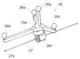
次に、断層面指示デバイスであるポインタ26について説明する。
【0033】
図2に示すようにポインタ26には、ポインタ26の位置及び姿勢が特定可能なようにポインタ本体26eに対して4つの反射球26a〜26dが配置されている。尚、反射球は少なくとも3つ必要であるが、この実施の形態では4つ設けることで、高い位置検出精度が得られるようになっている。
【0034】
また、ポインタ26には取付具26fが設けられており、ポインタ26はこの取付具26fにより穿刺針27に取り付けられる。このポインタ26は、穿刺針27の先端27aから一定距離だけ離間した所定の位置に取り付けられ、これによりポインタ26の位置と、穿刺針27の先端27aの位置とは一定の位置関係になっている。パーソナルコンピュータ19は、位置検出デバイス9から入力するポインタ26の位置及び姿勢に基づいて穿刺針27の先端27aの位置を算出し、この先端27aの位置を、撮影断面の中心位置を示す位置(即ち、被検体の断面位置)として制御部23に出力する。
【0035】
上記のようにポインタ26を穿刺針27の所定の位置に取り付け、穿刺針27の先端27aの位置を常に撮影断面の中心位置となるように構成した場合、モニタ13には、穿刺針27の画像(穿刺針27の部分だけ黒い線となる画像)を常に含み、画像の中心に穿刺針27の先端が位置する断層像が表示されることになる。
【0036】
ところで、ポインタ26の取付具26fの個体差、取付誤差などに起因して、ポインタ26と穿刺針27とがずれ、穿刺針27が撮影できない(穿刺針27と断層像とずれる)ことがある。
【0037】
次に、上記ポインタ26と穿刺針27とのずれを補正する方法について説明する。
【0038】
まず、ポインタ26が指示する断層面を撮影する穿刺モニタリング時のモードにおいて、撮影断面の位置及び向きを調整するための調整モードにする。前述したように穿刺モニタリング時には、位置検出デバイス9によって検出されるポインタ26の位置及び姿勢に基づいて穿刺針27の先端27aの位置が、撮影断面の中心位置となるように自動的に被検体の断面位置を決定して撮影するが、前記調整モード時には、前記決定した被検体の断面位置や向きを、マウスなどの入力手段により調整することができるようになっている。即ち、調整モード時には、入力手段によって適宜指示された移動量及び回転量がオフセット量として与えられ、ポインタ26の位置及び姿勢に基づいて決定した被検体の断面位置及び向きを、前記オフセット量により補正するようにしている。
【0039】
図3は上記調整モード時に実際に撮影される断面位置を調整する方法の一例を説明するために用いた図である。
【0040】
図3に示すように調整モード時のモニタ13には、撮影断面の幾何学的な3次元表示面(1) 、及び撮影断面をxy面、yz面、zx面に投影した場合の断面位置を示す各表示面(2) 〜(4) が表示される。尚、実際に撮影されている断層像も表示されるが、図3上では省略されている。
【0041】
また、モニタ13には、マウスによって操作可能な移動ボタン40、回転ボタン42、xyzの数値をアップダウンさせるアップダウンボタン44等が表示される。
【0042】
ここで、移動ボタン40が押されている場合には、ある表示画面上でマウス操作により断面位置を移動させることができる。即ち、マウス・ポインタを断面位置に合わせ、ボタンを押したままマウス・ポインタを移動させること(ドラッグすること)によって、断面位置を移動させることができる。ある一面での移動結果は、他の3面にも反映される。
【0043】
同様に、回転ボタン42が押されている場合には、ある表示画面上でマウス操作により断面の向きを変更(回転)させることができる。ある一面での回転結果は、他の3面にも反映される。
【0044】
変更結果は、1)変更される毎に送信、2)確定ボタンを押すことで送信の2パターンから選択できる。回転の際の回転中心軸は、x,y,z軸であるが、必要に応じて任意の直線を回転中心軸としてもよい。
【0045】
また、マウスでアップダウンボタン44を操作してxyzの数値を入力したり、キーボードでxyzの数値を入力してもよい。
【0046】
尚、変更処理はリセットボタンによって変更を加える前の状態に戻したり、取消ボタンで直前の処理を取り消して前の状態に戻すこともできる。
【0047】
ところで、上記撮影断面の位置や向きを調整するためのマウス操作等は、実際に撮影された断層像を見ながら、穿刺針27が断層像の所定の位置(例えば、穿刺針27の先端27aが断層像の中心に位置し、かつ穿刺針27が画面上で水平となる位置)に撮影されるように行われる。そして、調整モードを終了させると、その調整モードで調整された数値がオフセット量として記憶され、その後の穿刺モニタリング時にポインタ26(即ち、穿刺針27)を移動させた場合には、常に穿刺針27が断層像に撮影され、かつその先端27aが断層像の中心に位置するように断面位置及び向きが決定されて撮影される。
【0048】
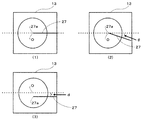
図4は調整モード時に実際に撮影される断面位置を調整する方法の他の例を説明するために用いた図である。
【0049】
この方法は、撮影断面が表示されている画面から、本来撮影されるべき位置と実際に撮影されている位置の変位を求め、それを入力することで補正を行う。
【0050】
例えば、図4(1)に示すようにモニタ13には、穿刺針27が水平で、先端27aが断層像の中心Oにくるようになっているにもかかわらず、図4(2)に示すように穿刺針27が傾いている場合、その傾き量θを入力することで、そのずれ量θを補正する。同様に、図4(3)に示すように穿刺針27が平行にずれている場合は、そのずれ量dを入力することで、ずれ量dを補正する。
【0051】
前記ずれ量θやdは、実際に撮影されている穿刺針27をマウス・ポインタがトレースするようにマウス操作することで、自動的に算出するようにしてもよい。また、撮影断面が表示されている画面上で、図4に示したようにマウス操作、数値入力によって調整することも可能である。更に、他の方法としては、例えば、ジョイスティック等の3次元位置入力装置を用いて、ジョイスティックの3次元の動きを直接断面の位置と連動させて補正してもよい。
【0052】
尚、この実施の形態では、赤外線カメラ25の座標系とMRI装置1の座標系とをリンクさせるための基準ツール17を設けるようにしているが、MRI装置1と赤外線カメラ25との位置関係が固定されている場合や、ポインタ26がある位置にある時のMRI装置1との位置関係が明確な場合は特に必要としない場合もある。
【0053】
また、この実施の形態では、ポインタ26を穿刺針27に取り付けた場合について説明したが、これに限らず、冷凍治療プローブなどの他の処置具に取り付けた場合にも適用できる。
【0054】
【発明の効果】
以上説明したように本発明によれば、被検体の断層面を指示部材によって指示し、その指示された断層面をリアルタイムに撮影する際に、前記指示部材の位置を検出する位置検出手段の検出出力に基づいて撮影する断面位置を決定して撮影するようにしたため、被検体の断層面の位置や向きの指定を簡単に行うことができる。特に、前記指示部材によって指示された本来撮影されるべき断層面の位置と、実際に撮影されている断層面の位置とがずれている場合には、その位置ずれを補正できるようにしたため、指示部材によって指示した断層面を確実に撮影することができる。
【図面の簡単な説明】
【図1】本発明に係る磁気共鳴イメージング装置の実施の形態を示す全体構成を示す模式図
【図2】図1中のポインタの構造の詳細を説明するために用いた斜視図
【図3】調整モード時に実際に撮影される断面位置を調整する方法の一例を説明するために用いた図
【図4】調整モード時に実際に撮影される断面位置を調整する方法の他の例を説明するために用いた図
【符号の説明】
1…MRI装置、3…上部磁石、5…下部磁石、7…支柱、9…位置検出デバイス、13…モニタ、19…パーソナルコンピュータ、23…制御部、24…被検体、25…赤外線カメラ、26…ポインタ、27…穿刺針[0001]
BACKGROUND OF THE INVENTION
The present invention relates to a magnetic resonance imaging apparatus, and more particularly to a technique for automatically capturing a tomographic image of a cross-sectional position of a subject set arbitrarily.
[0002]
[Prior art]
A magnetic resonance imaging apparatus (hereinafter referred to as an MRI apparatus) continuously measures a nuclear magnetic resonance signal (hereinafter referred to as an MR signal) from hydrogen, phosphorus, or the like in a subject, and a nuclear density distribution or relaxation time. The distribution is imaged.
[0003]
At present, the imaging object of the MRI apparatus that is widely used in the clinic is the proton of the main constituent substance of the subject. The MRI apparatus images the form or function of the human head, abdomen, limbs, etc. in a two-dimensional or three-dimensional manner by imaging the spatial distribution of the proton density and the spatial distribution of the relaxation phenomenon in the excited state.
[0004]
A general MRI apparatus has a magnet that generates a static magnetic field around a patient, a gradient coil that generates a gradient magnetic field in this space, and an RF that generates a high-frequency magnetic field pulse (hereinafter referred to as an RF pulse) in this region. The coil includes an RF receiving coil that detects an echo signal (hereinafter referred to as an MR signal) emitted by nuclear magnetic resonance of a nucleus of a patient's living tissue.
[0005]
The gradient magnetic field coils are composed of XYZ orthogonal three-axis gradient magnetic field coils, and each generate a gradient magnetic field in response to a signal from a gradient magnetic field power source. The RF coil generates an RF pulse according to the signal from the RF transmitter. The signal of the RF coil is detected by the RF receiving coil, processed by the signal processing unit, and converted into an image signal by calculation.
[0006]
The image signal is displayed as a tomographic image on the display unit. The gradient magnetic field power source, the RF transmission unit, the signal detection unit, and the like are controlled by the control unit, and the control time chart is generally called a pulse sequence. The patient lies on the bed and is transported to a space in the apparatus surrounded by an RF receiving coil, an RF coil, a gradient magnetic field coil, and the like, and a tomographic image is taken.
[0007]
In an I-MRI apparatus (abbreviation for Interventional-MRI apparatus or Intraoperative-MRI apparatus) used for cardiac imaging using such an MRI apparatus, monitoring of a puncture needle during surgery, percutaneous treatment, etc. There is a demand to set the tomographic plane to be photographed arbitrarily.
[0008]
As a method for arbitrarily setting a tomographic plane to be imaged, a method of displaying an MRI image on a monitor, clicking a button on the screen using a graphical user interface (GUI), and determining a tomographic image to be imaged next (Magnetic Resonace in Medicine: Real-time interactive MRI on a conventional scanner; AB.Kerr et al., 38, pp.355-367 (1997)) and methods using a 3D mouse (USP-5512827) Has been.
[0009]
In these methods, the position and orientation of the tomographic plane to be photographed must be adjusted and set by an input means such as a mouse, and therefore, the MRI apparatus can adjust the position and orientation of the tomographic plane to be photographed more easily. It is desirable that it can be set. As such a technique, an MRI apparatus for determining a tomographic plane to be imaged using a tomographic plane indicating device (pointer or the like) such as USP-5365927 or USP-6026315 has been proposed.
[0010]
In USP-5365927, a light emitting diode is provided on a pointer which is a tomographic plane indicating device, and the position pointed by the operator is detected by an infrared camera, or a pointer is provided at the tip of an arm provided with a sensor at the joint. The position of the pointer is detected based on the angle of the joint of the arm and the tomographic plane is automatically adjusted based on the detected position.
[0011]
USP-6026315 is to automatically determine and photograph the tomographic plane indicated by using two infrared cameras and a pointer provided with three reflecting spheres.
[0012]
On the other hand, since the patient at the time of imaging with the MRI apparatus is confined in a closed space, the patient may feel pain due to a feeling of occlusion or a feeling of pressure. Therefore, an open-type MRI apparatus has been proposed that does not give pain to the patient who is photographing. Since this open-type MRI apparatus can access a patient from an open part, a tomographic plane can be easily indicated using a pointer or the like, and the indicated tomographic plane can be photographed in real time. -Development as an MRI system is in progress.
[0013]
[Problems to be solved by the invention]
By the way, the open-type MRI apparatus has less restrictions on the movement and posture of the patient and the operator, and the operator can indicate the tomographic plane using a pointer or the like and can photograph various tomographic planes in real time. However, the conventional means for adjusting and setting the position and orientation of the tomographic plane has a low degree of freedom and there are problems with ease of use, and means for adjusting and setting the position and orientation of the tomographic plane having a higher degree of freedom is desired.
[0014]
Further, when photographing a designated tomographic plane using a pointer or the like, it is desired to photograph the tomographic plane accurately (that is, so as not to photograph a tomographic plane different from the designated tomographic plane). In particular, when using a treatment tool such as a puncture needle and photographing a designated tomographic plane so that the treatment tool is displayed in a tomographic image, it is necessary to match the designated tomographic plane with the photographed tomographic plane. is there.
[0015]
The present invention has been made in view of such circumstances, and when photographing a tomographic plane of a subject in real time, the position and orientation of the tomographic plane can be easily designated, and the designated tomographic plane It is an object of the present invention to provide a magnetic resonance imaging apparatus that can reliably capture images.
[0016]
[Means for Solving the Problems]
In order to achieve the above object, the invention according to
The invention according to
The invention according to
According to a fourth aspect of the present invention, when the cross-sectional position that is actually photographed is adjusted, the adjustment means uses the movement or rotation result used for the adjustment, or the inclination amount or the deviation amount as an offset amount. It is memorized as a feature.
[0017]
That is, the cross-sectional position of the subject to be imaged is indicated by the indicating member, and the position of the indicating member is detected by the position detecting means. The pointing member includes, for example, at least three reflectors or light emitters arranged in a predetermined positional relationship, and the position detection unit includes an imaging unit that photographs the three reflectors or light emitters. Based on the position of the reflector or light emitter on the imaging surface, the position of the pointing member (including the rotational position around each coordinate axis) in a predetermined three-dimensional coordinate system is detected.
[0018]
When the position of the indicator member is detected, the position of the indicator member and the cross-sectional position of the subject indicated by the indicator member are in a fixed relationship. The cross-sectional position of the subject to be imaged is output based on the above.
[0019]
By the way, by attaching the indicating member to a treatment instrument such as a puncture needle or a cryotherapy probe with a predetermined attachment, a tomographic image including the treatment instrument can be taken. However, when the positional relationship between the indication member and the treatment instrument is not accurate (for example, when there is an attachment error of the indication member due to the attachment tool), a tomographic image including the treatment tool and a tomographic image actually taken Will shift.
[0020]
Therefore, the adjusting means can set an arbitrary offset amount with respect to the position of the pointing member detected by the position detecting means in order to correct the shift between the two tomographic images.
[0021]
As the offset amount setting method, for example, an offset amount that manually indicates a movement amount in each coordinate axis direction or a rotation amount around each coordinate axis so that a desired tomographic image is displayed while viewing a currently displayed tomographic image. Set.
[0022]
DETAILED DESCRIPTION OF THE INVENTION
A preferred embodiment of a magnetic resonance imaging apparatus according to the present invention will be described below in detail with reference to the accompanying drawings.
[0023]
FIG. 1 is a schematic diagram showing an overall configuration showing an embodiment of a magnetic resonance imaging apparatus according to the present invention.
[0024]
The
[0025]
A gradient magnetic field generator (not shown) of the
[0026]
The
[0027]
The
[0028]
The
[0029]
The position of the
[0030]
The
[0031]
In the
[0032]
Next, the
[0033]
As shown in FIG. 2, the
[0034]
The
[0035]
When the
[0036]
By the way, the
[0037]
Next, a method for correcting the deviation between the
[0038]
First, in the puncture monitoring mode in which the tomographic plane indicated by the
[0039]
FIG. 3 is a diagram used for explaining an example of a method for adjusting the cross-sectional position actually taken in the adjustment mode.
[0040]
As shown in FIG. 3, on the
[0041]
Further, the
[0042]
Here, when the
[0043]
Similarly, when the
[0044]
The change result can be selected from two patterns of 1) transmission every time it is changed and 2) transmission by pressing the confirm button. The rotation center axes at the time of rotation are the x, y, and z axes, but an arbitrary straight line may be used as the rotation center axis as necessary.
[0045]
Alternatively, the xyz value may be input by operating the up / down
[0046]
The change process can be returned to the state before the change is made with the reset button, or the previous process can be canceled with the cancel button to return to the previous state.
[0047]
By the way, the mouse operation or the like for adjusting the position and orientation of the imaging section is performed while the
[0048]
FIG. 4 is a diagram used for explaining another example of a method for adjusting the cross-sectional position actually photographed in the adjustment mode.
[0049]
In this method, a displacement between a position where an image should be photographed and a position where an image is actually photographed is obtained from a screen on which a photographing section is displayed, and correction is performed by inputting the displacement.
[0050]
For example, as shown in FIG. 4 (1), the
[0051]
The shift amounts θ and d may be automatically calculated by operating the mouse so that the mouse pointer traces the
[0052]
In this embodiment, the
[0053]
Moreover, although this embodiment demonstrated the case where the
[0054]
【The invention's effect】
As described above, according to the present invention, when the tomographic plane of the subject is instructed by the indicating member, and the tomographic plane instructed is imaged in real time, the position detecting unit detects the position of the indicating member. Since the cross-sectional position to be imaged is determined based on the output and the image is captured, it is possible to easily specify the position and orientation of the tomographic plane of the subject. In particular, when the position of the tomographic plane to be photographed that is instructed by the pointing member is misaligned with the position of the tomographic plane that is actually photographed, the misalignment can be corrected. The tomographic plane indicated by the member can be reliably imaged.
[Brief description of the drawings]
FIG. 1 is a schematic diagram showing an overall configuration showing an embodiment of a magnetic resonance imaging apparatus according to the present invention. FIG. 2 is a perspective view used for explaining details of a pointer structure in FIG. FIG. 4 is a diagram used for explaining an example of a method for adjusting a cross-sectional position actually photographed in the adjustment mode. FIG. 4 is for explaining another example of a method for adjusting a cross-sectional position actually photographed in the adjustment mode. Diagram used for explanation [Explanation of symbols]
DESCRIPTION OF
Claims (5)
撮影する被検体の断面位置を指示するための指示部材と、
前記指示部材の位置を検出する位置検出手段と、
前記位置検出手段によって検出された前記指示部材の位置に対して任意のオフセット量を設定するための調整手段と、
前記位置検出手段によって検出された前記指示部材の位置と前記調整手段によって設定されたオフセット量とに基づいて前記被検体の断面位置を出力する前記断面位置出力手段と、
を備えたことを特徴する磁気共鳴イメージング装置。An imaging sequence for applying a static magnetic field, a high frequency pulse, and a gradient magnetic field to a subject is executed to receive a magnetic resonance signal generated from the subject, and a tomographic image is generated and displayed based on the received magnetic resonance signal A magnetic resonance imaging apparatus that controls the application of the high-frequency pulse and the gradient magnetic field based on the cross-sectional position of the subject output from the cross-sectional position output means, and generates and displays a tomographic image of the cross-sectional position In a magnetic imaging apparatus
An indicating member for indicating the cross-sectional position of the subject to be imaged;
Position detecting means for detecting the position of the indicating member;
Adjusting means for setting an arbitrary offset amount with respect to the position of the indicating member detected by the position detecting means;
The cross-sectional position output means for outputting the cross-sectional position of the subject based on the position of the pointing member detected by the position detecting means and the offset amount set by the adjusting means;
A magnetic resonance imaging apparatus comprising:
前記位置検出手段は、前記ポインタの位置及び姿勢に基づいて穿刺針の先端の位置を算出し、前記算出された穿刺針の先端の位置を前記指示部材の位置として検出することを特徴とする請求項1に記載の磁気共鳴イメージング装置。The position detection means calculates the position of the tip of the puncture needle based on the position and posture of the pointer, and detects the calculated position of the tip of the puncture needle as the position of the pointing member. Item 2. The magnetic resonance imaging apparatus according to Item 1.
前記表示画面上において断面位置を移動又は回転させると、その移動又は回転結果に基づいて実際に撮影される断面位置を調整する、
ことを特徴とする請求項1又は2に記載の磁気共鳴イメージング装置。And a monitor for displaying a display screen showing at least one of a geometric three-dimensional display surface of the photographing section and a display position indicating a sectional position when the photographing section is projected onto one or more different surfaces. ,
When the cross-sectional position is moved or rotated on the display screen, the cross-sectional position that is actually photographed is adjusted based on the movement or rotation result.
The magnetic resonance imaging apparatus according to claim 1 or 2.
前記断層像に含まれる前記穿刺針の傾き量又はずれ量を入力すると、その入力された傾き量又はずれ量に基づいて、実際に撮影される断面位置を調整する、
ことを特徴とする請求項1又は2に記載の磁気共鳴イメージング装置。A monitor for displaying a tomographic image of the subject including a puncture needle punctured on the subject;
When the tilt amount or shift amount of the puncture needle included in the tomographic image is input, the cross-sectional position that is actually imaged is adjusted based on the input tilt amount or shift amount.
The magnetic resonance imaging apparatus according to claim 1 or 2.
ことを特徴とする請求項3又は4に記載の磁気共鳴イメージング装置。When the cross-sectional position that is actually photographed is adjusted, the adjustment means stores the movement or rotation result used for the adjustment, or the tilt amount or the shift amount as an offset amount.
5. The magnetic resonance imaging apparatus according to claim 3, wherein the magnetic resonance imaging apparatus is a magnetic resonance imaging apparatus.
Priority Applications (1)
| Application Number | Priority Date | Filing Date | Title |
|---|---|---|---|
| JP2002150914A JP3988183B2 (en) | 2002-05-24 | 2002-05-24 | Magnetic resonance imaging system |
Applications Claiming Priority (1)
| Application Number | Priority Date | Filing Date | Title |
|---|---|---|---|
| JP2002150914A JP3988183B2 (en) | 2002-05-24 | 2002-05-24 | Magnetic resonance imaging system |
Publications (3)
| Publication Number | Publication Date |
|---|---|
| JP2003339664A JP2003339664A (en) | 2003-12-02 |
| JP2003339664A5 JP2003339664A5 (en) | 2005-10-06 |
| JP3988183B2 true JP3988183B2 (en) | 2007-10-10 |
Family
ID=29768651
Family Applications (1)
| Application Number | Title | Priority Date | Filing Date |
|---|---|---|---|
| JP2002150914A Expired - Fee Related JP3988183B2 (en) | 2002-05-24 | 2002-05-24 | Magnetic resonance imaging system |
Country Status (1)
| Country | Link |
|---|---|
| JP (1) | JP3988183B2 (en) |
Families Citing this family (3)
| Publication number | Priority date | Publication date | Assignee | Title |
|---|---|---|---|---|
| JP4528136B2 (en) | 2005-01-11 | 2010-08-18 | 株式会社日立製作所 | Surgical device |
| JP4793914B2 (en) * | 2005-11-15 | 2011-10-12 | 株式会社日立メディコ | Magnetic resonance imaging system |
| JP4717683B2 (en) * | 2006-03-30 | 2011-07-06 | 株式会社日立メディコ | Medical image display device |
-
2002
- 2002-05-24 JP JP2002150914A patent/JP3988183B2/en not_active Expired - Fee Related
Also Published As
| Publication number | Publication date |
|---|---|
| JP2003339664A (en) | 2003-12-02 |
Similar Documents
| Publication | Publication Date | Title |
|---|---|---|
| EP2503934B1 (en) | Systems and methods for tracking positions between imaging modalities and transforming a displayed three-dimensional image corresponding to a position and orientation of a probe | |
| US8374678B2 (en) | Medical apparatus with image acquisition device and position determination device combined in the medical apparatus | |
| US6275721B1 (en) | Interactive MRI scan control using an in-bore scan control device | |
| US6796943B2 (en) | Ultrasonic medical system | |
| KR101618213B1 (en) | Information providing method and apparatus for aligning x-ray tube and detector of mobile x-ray, and wireless detector | |
| JP2003527880A (en) | Apparatus and method for medical diagnostics and medical guided interventions and treatments | |
| JP2010269067A (en) | Treatment support device | |
| JP4717683B2 (en) | Medical image display device | |
| KR100593570B1 (en) | Magnetic resonance imaging method and apparatus | |
| JP4032293B2 (en) | Ultrasound-magnetic resonance combined medical device | |
| US20020172328A1 (en) | 3-D Navigation for X-ray imaging system | |
| JP2011050625A (en) | Treatment support system | |
| JP3988183B2 (en) | Magnetic resonance imaging system | |
| JP2001204718A (en) | Radiographic device | |
| JP2010051615A (en) | Magnetic resonance imaging apparatus | |
| JP2009279209A (en) | Surgical instrument guiding surgery supporting system | |
| US20200046318A1 (en) | Ultrasonic diagnostic apparatus | |
| JP2004141269A (en) | Magnetic resonance imaging apparatus | |
| JP3980406B2 (en) | Magnetic resonance imaging device | |
| JP4565885B2 (en) | Nuclear magnetic resonance imaging system | |
| JP4871505B2 (en) | Nuclear magnetic resonance imaging system | |
| US20230149112A1 (en) | System and method for a navigated procedure | |
| JP5507859B2 (en) | Magnetic resonance imaging system | |
| JP4793914B2 (en) | Magnetic resonance imaging system | |
| JP2009195481A (en) | Medical image diagnostic apparatus |
Legal Events
| Date | Code | Title | Description |
|---|---|---|---|
| A521 | Written amendment |
Free format text: JAPANESE INTERMEDIATE CODE: A523 Effective date: 20050516 |
|
| A621 | Written request for application examination |
Free format text: JAPANESE INTERMEDIATE CODE: A621 Effective date: 20050516 |
|
| A977 | Report on retrieval |
Free format text: JAPANESE INTERMEDIATE CODE: A971007 Effective date: 20061204 |
|
| A131 | Notification of reasons for refusal |
Free format text: JAPANESE INTERMEDIATE CODE: A131 Effective date: 20061207 |
|
| A521 | Written amendment |
Free format text: JAPANESE INTERMEDIATE CODE: A523 Effective date: 20070202 |
|
| TRDD | Decision of grant or rejection written | ||
| A01 | Written decision to grant a patent or to grant a registration (utility model) |
Free format text: JAPANESE INTERMEDIATE CODE: A01 Effective date: 20070625 |
|
| A61 | First payment of annual fees (during grant procedure) |
Free format text: JAPANESE INTERMEDIATE CODE: A61 Effective date: 20070708 |
|
| FPAY | Renewal fee payment (event date is renewal date of database) |
Free format text: PAYMENT UNTIL: 20100727 Year of fee payment: 3 |
|
| R150 | Certificate of patent or registration of utility model |
Free format text: JAPANESE INTERMEDIATE CODE: R150 |
|
| FPAY | Renewal fee payment (event date is renewal date of database) |
Free format text: PAYMENT UNTIL: 20110727 Year of fee payment: 4 |
|
| FPAY | Renewal fee payment (event date is renewal date of database) |
Free format text: PAYMENT UNTIL: 20120727 Year of fee payment: 5 |
|
| FPAY | Renewal fee payment (event date is renewal date of database) |
Free format text: PAYMENT UNTIL: 20120727 Year of fee payment: 5 |
|
| FPAY | Renewal fee payment (event date is renewal date of database) |
Free format text: PAYMENT UNTIL: 20130727 Year of fee payment: 6 |
|
| LAPS | Cancellation because of no payment of annual fees |