JP3985602B2 - Injection rate control device for internal combustion engine - Google Patents
Injection rate control device for internal combustion engine Download PDFInfo
- Publication number
- JP3985602B2 JP3985602B2 JP2002184420A JP2002184420A JP3985602B2 JP 3985602 B2 JP3985602 B2 JP 3985602B2 JP 2002184420 A JP2002184420 A JP 2002184420A JP 2002184420 A JP2002184420 A JP 2002184420A JP 3985602 B2 JP3985602 B2 JP 3985602B2
- Authority
- JP
- Japan
- Prior art keywords
- injection
- pilot
- injections
- amount
- main
- Prior art date
- Legal status (The legal status is an assumption and is not a legal conclusion. Google has not performed a legal analysis and makes no representation as to the accuracy of the status listed.)
- Expired - Fee Related
Links
Images


Description
【0001】
【発明の属する技術分野】
本発明は、内燃機関の各気筒毎に対応して搭載されたインジェクタの電磁弁の駆動を、内燃機関の1燃焼行程中に複数回実施することで、メイン噴射の前に2回以上のパイロット噴射を行なう内燃機関用噴射率制御装置に関するもので、特に多段噴射における1噴射当たりの噴射回数が3回以上の時に、インターバル依存性の補正パラメータとして、直前噴射の更に前の先行噴射の噴射量および先行噴射と直前噴射との間のインターバルをも考慮して当該噴射の噴射開始時期補正または噴射期間補正を実施する内燃機関用噴射率制御装置に係わる。
【0002】
【従来の技術】
従来より、ディーゼルエンジン用の燃料噴射装置として、コモンレールに蓄圧した高圧燃料をエンジンの各気筒内に噴射供給する蓄圧式燃料噴射システムが知られている。このような蓄圧式燃料噴射システムにおいては、主噴射の開始時から安定した燃焼を行なって燃焼騒音やエンジン振動の低減、更には排気ガス性能の向上を目的として、エンジントルクと成り得る主噴射(メイン噴射)に先立って複数回の微少の先立ち噴射(パイロット噴射)を行なうようにしている。ここで、通常、エンジンの各気筒への噴射量制御は、エンジンの運転状態または運転条件によって設定される指令噴射量とセンサ等によって検出されるコモンレール圧力とから算出される指令噴射期間に応じて、インジェクタの電磁弁に印加される噴射量指令値を決定することで実施される。
【0003】
ここで、上記のようなパイロット噴射を行なう多段噴射においては、パイロット噴射により生じるコモンレール内の圧力脈動と当該インジェクタ間の高圧配管(噴射鋼管)内の圧力脈動によって、パイロット噴射とメイン噴射との無噴射間隔(インターバル)に依存してメイン噴射量が脈動するという課題がある(図15参照)。このような課題に対し、特開平6−101552号公報や特開平10−266888号公報等には、パイロット噴射とメイン噴射との間の噴射インターバル(パイロットインターバル)に応じてメイン噴射量を補正するようにしたインジェクタ噴射量制御方法が提案されている。
【0004】
【発明が解決しようとする課題】
ところが、第2パイロット噴射−第1パイロット噴射−メイン噴射のような3回噴射時には、メイン噴射時の高圧配管内の圧力脈動が、第1パイロット噴射よりも前に先行して実施される第2パイロット噴射の影響を受けて、第1パイロット噴射−メイン噴射のような2回噴射時とは異なる脈動(周期、振幅の変化)となる。そのため、3回噴射時において、精度良くメイン噴射量を補正するためには、メイン噴射の直前に先行して実施される第1パイロット噴射の影響だけでなく、第1パイロット噴射の更に前の第2パイロット噴射、あるいはその前の前…の噴射量および噴射インターバルの影響を考慮してメイン噴射開始時期およびメイン噴射期間を補正することが望ましいことが分かった(図16参照)。
【0005】
【発明の目的】
本発明の目的は、多段噴射における噴射回数が3回以上の時に、直前噴射の前に先行して実施される先行噴射の噴射量、および直前噴射と先行噴射との間の無噴射間隔をも考慮して、当該噴射の噴射開始時期補正または当該噴射の噴射期間補正を実施することにより、当該インジェクタ内および高圧配管内の圧力脈動の影響による当該噴射の噴射量脈動を防止することのできる内燃機関用噴射率制御装置を提供することにある。
【0006】
【課題を解決するための手段】
請求項1に記載の発明によれば、多段噴射における噴射回数が3回以上の時に、当該噴射の直前に先行して実施される直前噴射の噴射量、および当該噴射と直前噴射との間の無噴射間隔だけでなく、直前噴射の前に先行して実施される先行噴射の噴射量、および直前噴射と先行噴射との間の無噴射間隔をも使用するとともに先行噴射と当該噴射との間の噴射インターバルをも使用することで、直前噴射および先行噴射にてそれぞれ生じるコモンレール内の圧力脈動の当該噴射への影響を考慮して、当該噴射の噴射開始時期補正または当該噴射の噴射期間補正を実施することにより、当該インジェクタ内および高圧配管内の圧力脈動の影響による当該噴射の噴射量脈動を防止することができる。
【0007】
請求項2に記載の発明によれば、多段噴射として、メイン噴射の前に2回以上のパイロット噴射を行なうマルチ噴射を用いても良く、あるいはメイン噴射の後に2回以上のアフター噴射を行なうマルチ噴射を用いても良く、あるいはメイン噴射の前に1回以上のパイロット噴射を行ない、更にメイン噴射の後に1回以上のアフター噴射を行なうマルチ噴射を用いても良い。
請求項3に記載の発明によれば、多段噴射における噴射回数が3回に設定された3回噴射時に、当該噴射をメイン噴射とすると、直前噴射は第1パイロット噴射となり、先行噴射は第2パイロット噴射となることを特徴としている。また、請求項4に記載の発明によれば、多段噴射における噴射回数が4回に設定された4回噴射時に、当該噴射をメイン噴射とすると、直前噴射は第1パイロット噴射となり、先行噴射は第3、第2パイロット噴射となることを特徴としている。
【0008】
請求項5に記載の発明によれば、メイン噴射の直前に先行して実施される第1パイロット噴射の噴射量、およびメイン噴射と第1パイロット噴射との間の無噴射間隔だけでなく、多段噴射における噴射回数、内燃機関の気筒内に噴射される燃料の噴射圧力、および第3パイロット噴射の噴射量、前記第2パイロット噴射の噴射量、第2パイロット噴射と第1パイロット噴射との間の無噴射間隔、第3パイロット噴射と第2パイロット噴射との間の無噴射間隔、第3パイロット噴射と第1パイロット噴射との間の無噴射間隔、第2パイロット噴射とメイン噴射との間の無噴射間隔、第3パイロット噴射とメイン噴射との間の無噴射間隔のうちのいずれか少なくとも1個をも考慮して、メイン噴射の噴射開始時期補正またはメイン噴射の噴射期間補正を実施することにより、当該インジェクタ内および高圧配管内の圧力脈動の影響によるメイン噴射の噴射量脈動を防止することができる。
【0009】
【発明の実施の形態】
発明の実施の形態を実施例に基づき図面を参照して説明する。
[第1実施例の構成]
図1ないし図10は本発明の第1実施例を示したもので、図2はコモンレール式燃料噴射システムの全体構成を示した図である。
【0010】
本実施例のコモンレール式燃料噴射システムは、4気筒ディーゼルエンジン等の内燃機関(以下エンジンと言う)1の各気筒に噴射供給する燃料噴射圧力に相当する高圧燃料を蓄圧する蓄圧容器としてのコモンレール2と、吸入した燃料を加圧してコモンレール2内に圧送する燃料供給ポンプとしてのサプライポンプ3と、コモンレール2内に蓄圧された高圧燃料をエンジン1の各気筒内に噴射供給する複数個(本例では4個)のインジェクタ4と、サプライポンプ3および複数個のインジェクタ4を電子制御する電子制御ユニット(以下ECUと呼ぶ)10とを備えている。
【0011】
エンジン1の各気筒(シリンダ)の吸気ポートは、吸気弁(インテークバルブ)11により開閉され、排気ポートは、排気弁(エキゾーストバルブ)12により開閉される。また、各シリンダ内には、連接棒を介してクランクシャフト(図示せず)に連結されたピストン13が摺動自在に配設されている。そして、エンジン1を収容するエンジンルーム(図示せず)内の走行風を受け易い場所には、ラジエータ14が配設されている。ラジエータ14には、エンジン1を冷却する冷却水の温度(冷却水温)を検出する冷却水温センサ37が設置されている。
【0012】
ここで、エンジン1の運転中に、シリンダ内で燃焼した排気ガスは、排気管15を通り、バリアブル・ジアメトリ・ターボ(VGT)16のタービンの駆動源となった後に、触媒(図示せず)、マフラー(図示せず)を経て排出される。上記のVGT16の制御は、吸気圧センサと過給圧力センサ44とVGTポジションセンサ47の信号とに基づいて行なわれる。過給(圧縮)され高温になった吸入空気は、インタクーラ18で冷却された後に、エンジン1の吸気ポートを経てシリンダ内へ導入される。
【0013】
そして、吸気管17の途中には、吸気管17内の吸気通路を開閉してエンジン1に供給する吸入空気量(吸気量)を調整するための吸気絞り弁(スロットルバルブ)19が配設され、このスロットルバルブ19の弁開度は、ECU10からの信号により作動するアクチュエータ20によって調節される。なお、アクチュエータ20内には、スロットルバルブ19の弁開度を検出するスロットルポジションセンサ(図示せず)が装備されている。スロットルポジションセンサとしては、スロットルバルブ19の弁開度を全閉のアイドリング時と全開に近い高負荷時に分けて感知し、ECU10へ送信するセンサを用いても良い。また、吸気管17の吸気ポート近傍には、ECU10からの信号により作動する渦流制御弁(スワールコントロールバルブ:以下SCVと言う)21が配設されている。そのSCV21は、吸気温センサ45を設置した吸気通路22を迂回するバイパス路23内に設置され、低負荷時に通電停止(OFF)されて閉弁し、高負荷時に通電(ON)されて開弁する。
【0014】
また、本実施例の吸気管17には、排気管15を流れる排気ガスの一部の排気ガス(排気再循環ガス:EGRガス)を吸気管17へ導く排気ガス還流管24が接続されている。そして、吸気管17と排気ガス還流管24との合流部には、排気ガス再循環装置用バルブ(EGRバルブ)25が設置されている。したがって、シリンダ内に吸い込まれる吸入空気は、窒素酸化物(NOx)の生成量を少なくする目的で、エンジン1の運転状態毎に設定された排気ガス還流量になるようにEGRバルブ25の弁開度を制御し、排気管15からの排気ガスとミキシングされることになる。なお、排気ガス還流量(EGR量)は、吸入空気量センサ43と吸気温センサ45と排気O2 センサ48とEGRポジションセンサ46からの信号で、所定値を保持できるようにフィードバック制御している。
【0015】
コモンレール2には、連続的に燃料の噴射圧力に相当する高圧燃料が蓄圧される必要があり、そのためにコモンレール2に蓄圧される高圧燃料は、高圧配管26を介してサプライポンプ3から供給されている。なお、コモンレール2から燃料タンクへ燃料をリリーフするリリーフ配管(図示せず)には、燃料噴射圧力が限界設定圧を越えることがないように、圧力を逃がすためのプレッシャリミッタ27が取り付けられている。また、燃料の噴射圧力に相当するコモンレール2内に蓄圧された燃料圧力(コモンレール圧力とも言う)は、燃料圧力センサ30等の燃料圧力検出手段によって測定される。
【0016】
サプライポンプ3は、図示しない燃料タンクから燃料を汲み上げるフィードポンプ(図示せず)、およびコモンレール2への高圧燃料の圧送量(吐出量)を調整するための電磁弁(例えば吸入調量弁)等のアクチュエータ(図示せず)を内蔵する高圧供給ポンプである。このサプライポンプ3内には、燃料タンクから吸入される燃料の温度を検出する燃料温度センサ36が設置されている。
【0017】
複数のインジェクタ4は、エンジン1のシリンダブロックに(各気筒#1〜#4に個別に対応して)取り付けられ、コモンレール2より分岐する複数の噴射鋼管(以下高圧配管と呼ぶ)29の下流端に接続されている。これらのインジェクタ4は、各気筒毎内に高圧燃料を噴射する複数個の噴射孔を有する燃料噴射ノズル、この燃料噴射ノズル内に摺動自在に収容されたノズルニードルを開弁方向に駆動する電磁弁等の駆動手段(アクチュエータ)、およびノズルニードルを閉弁方向に付勢するスプリング等の付勢手段などから構成された電磁式燃料噴射弁である。なお、電磁弁の閉弁時には、ノズルニードルの後端部に連結したコマンドピストンの背圧を制御するための背圧制御室内の圧力が高まり、ノズルニードルが弁座に着座する。また、電磁弁の開弁時には、背圧制御室内の圧力が低くなり、ノズルニードルが弁座より離間(リフト)する。
【0018】
したがって、各気筒毎のインジェクタ4からエンジン1の各気筒内への燃料噴射は、例えば電磁弁が開弁している間、コモンレール2に蓄圧された高圧燃料がエンジン1の各気筒内に噴射供給されることで成される。ここで、インジェクタ4からのリーク燃料またはノズルニードルの背圧制御室からの排出燃料(リターン燃料)は、燃料還流路を経て燃料タンクに還流するように構成されている。なお、インジェクタ4のノズルニードルの開弁時間(燃料の噴射期間)が長い程、エンジン1の各気筒内に噴射される実際の噴射量が多くなる。
【0019】
ECU10には、制御処理、演算処理を行なうCPU、各種プログラムおよびデータを保存する記憶装置(ROM、スタンバイRAMまたはEEPROM、RAM等のメモリ)、入力回路、出力回路、電源回路、インジェクタ駆動回路およびポンプ駆動回路等の機能を含んで構成される周知の構造のマイクロコンピュータが設けられている。そして、燃料圧力センサ30からの電圧信号や、その他の各種センサからのセンサ信号は、A/D変換器でA/D変換された後に、ECU10に内蔵されたマイクロコンピュータに入力されるように構成されている。また、ECU10は、エンジン1をクランキングさせた後にエンジンキーをIG位置に戻して、図示しないイグニッションスイッチがオン(ON)すると、メモリ内に格納された制御プログラムに基づいて、例えばサプライポンプ3の電磁弁やインジェクタ4の電磁弁等の各制御部品のアクチュエータを電子制御するように構成されている。
【0020】
ここで、本実施例の気筒判別手段は、エンジン1のカムシャフトに対応して回転するシグナルロータ(例えばクランクシャフトが2回転する間に1回転する回転体)31と、このシグナルロータ31の外周に設けられた各気筒に対応した気筒歯(突起部)と、これらの気筒歯の接近と離間によって気筒判別信号パルス(G)を発生する気筒判別センサ(電磁ピックアップ)32とから構成されている。また、本実施例の回転速度検出手段は、エンジン1のクランクシャフトに対応して回転するシグナルロータ(例えばクランクシャフトが1回転する間に1回転する回転体)33と、このシグナルロータ33の外周に多数形成されたクランク角度検出用の歯(突起部)と、これらの歯の接近と離間によってNE信号パルスを発生するクランク角度センサ(電磁ピックアップ)34とから構成されている。このクランク角度センサ34は、シグナルロータ33が1回転(クランクシャフトが1回転)する間に複数のNE信号パルスを出力する。なお、特定のNE信号パルスは、各#1〜#4気筒のピストンの上死点(TDC)の位置に対応している。そして、ECU10は、NE信号パルスの間隔時間を計測することによってエンジン回転速度(NE)を検出する。
【0021】
そして、ECU10は、エンジン1の運転状態または運転条件に応じた最適な燃料の噴射圧力(以下コモンレール圧力と言う)を演算し、ポンプ駆動回路を介してサプライポンプ3の電磁弁を駆動する吐出量制御手段を有している。すなわち、ECU10は、通常のエンジン運転時に、エンジン回転速度(NE)と指令噴射量(QFIN)とに応じて目標燃料圧力(PFIN)を算出し、この目標燃料圧力(PFIN)を達成するために、サプライポンプ3の電磁弁へのポンプ駆動信号(駆動電流値)を調整して、サプライポンプ3より吐出される燃料の圧送量(ポンプ吐出量・ポンプ圧送量)を制御するように構成されている。
【0022】
さらに、より好ましくは、燃料噴射量の制御精度を向上させる目的で、燃料圧力センサ30によって検出されるコモンレール2内の燃料圧力(コモンレール圧力:Pc)がエンジン1の運転状態または運転条件に応じて設定される目標燃料圧力(PFIN)と略一致するように、サプライポンプ3の電磁弁へのポンプ駆動信号をフィードバック制御することが望ましい。なお、サプライポンプ3の電磁弁への駆動電流値の調整は、デューティ(DUTY)制御により行なうことが望ましい。すなわち、コモンレール圧力(Pc)と目標燃料圧力(PFIN)との圧力偏差に応じて単位時間当たりのポンプ駆動信号のオン/オフの割合(通電時間割合・DUTY比)を調整して、サプライポンプ3の電磁弁の開度を変化させるデューティ制御を用いることで、高精度なデジタル制御が可能になる。
【0023】
また、ECU10は、本発明の噴射量補正手段を構成するものであり、エンジン回転速度(NE)とアクセル開度(ACCP)と予め実験等により測定して作成した特性マップ(図示せず)とによって最適な指令噴射時期(TFIN)を算出する噴射時期決定手段と、エンジン回転速度(NE)とアクセル開度(ACCP)と予め実験等により測定して作成した特性マップ(図示せず)とによって最適な基本噴射量(Q)を算出する基本噴射量決定手段と、上記のようにエンジン1の運転状態または運転条件に応じて決定される基本噴射量(Q)に、燃料温度センサ36によって検出された燃料温度(THF)および冷却水温センサ37によって検出された冷却水温(THW)等を考慮した噴射量補正量を加味して指令噴射量(QFIN)を算出する指令噴射量決定手段と、コモンレール圧力(Pc)と指令噴射量(QFIN)と予め実験等により測定して作成した特性マップ(図示せず)とによって最適な指令噴射期間(噴射指令パルス時間:TQ)を算出する噴射期間決定手段と、インジェクタ駆動回路(EDU)を介してエンジン1の各気筒のインジェクタ4の電磁弁を駆動するインジェクタ駆動手段とから構成されている。なお、インジェクタ駆動回路(EDU)は、図7および図8の説明図に示したように、インジェクタ駆動手段より出力されるインジェクタ駆動指令(噴射量指令値、TQパルス)がONされてからOFFされるまでの間、エンジン1の各気筒のインジェクタ4の電磁弁にパルス状のインジェクタ駆動電流(インジェクタ噴射指令パルス)を印加する。
【0024】
ここで、本実施例では、エンジン1の運転状態または運転条件を検出する運転状態検出手段として、クランク角度センサ34等の回転速度検出手段およびアクセル開度センサ35を用いて基本噴射量(Q)、指令噴射時期(TFIN)、目標燃料圧力(PFIN)を演算するようにしているが、燃料圧力センサ30によって検出されるコモンレール圧力(Pc)、あるいは運転状態検出手段としてのその他のセンサ類(例えば燃料温度センサ36、冷却水温センサ37、燃料リーク温度センサ38、油温センサ39、アイドルアクセル位置センサ40、大気圧センサ41、大気温(外気温)センサ42、吸入空気量センサ43、過給圧力センサ44、吸気温センサ45、EGRポジションセンサ46、VGTポジションセンサ47、排気O2 センサ48、排気温センサ49、排気圧センサ50、スロットルポジションセンサ、吸気圧センサ、噴射時期センサ等)からの検出信号(エンジン運転情報)を加味して基本噴射量(Q)または指令噴射量(QFIN)、指令噴射時期(TFIN)および目標燃料圧力(PFIN)を補正するようにしても良い。
【0025】
そして、ECU10には、エンジンキーをシリンダ内に差し込んでST位置まで回すと、スタータスイッチがオン(ON)してスタータを通電するスタータ通電回路が接続されている。また、ECU10には、エンジン1により駆動されるトランスミッションのギアポジションを示す信号、運転者(ドライバー)がクラッチペダルを踏んだことを検出する信号、スタータへの通電信号、車速センサからの車速信号、エアコン用電磁クラッチ、エアコンのコンデンサ用電動ファン、エアコンの室内送風用ファン、ラジエータ用電動ファンやヘッドライト等の電気負荷、エアコン用コンプレッサやパワーステアリングやオイルポンプ等の駆動負荷等の車両情報を検出する信号が入力するように構成されている。
【0026】
ここで、本実施例のコモンレール式燃料噴射システムにおいては、エンジン1の特定気筒(k気筒)のインジェクタ4においてエンジン1の1周期(1行程:吸気行程−圧縮行程−膨張行程(爆発行程)−排気行程)中、つまりエンジン1のクランクシャフトが2回転(720°CA)する間、特にエンジン1の各気筒の1燃焼行程中に燃料を複数回に分けて噴射する多段噴射を行なうことが可能である。例えばエンジン1の圧縮行程中、膨張行程中にインジェクタ4の電磁弁の駆動を複数回実施することで、メイン噴射の前に複数回のパイロット噴射を行なうマルチ噴射、あるいはメイン噴射の後に複数回のアフター噴射を行なうマルチ噴射、あるいはメイン噴射の前に1回以上のパイロット噴射を行なうと共に、メイン噴射の後に1回以上のアフター噴射を行なうマルチ噴射が可能である。
【0027】
なお、本実施例では、マルチ噴射回数が4回に設定された4回噴射時でのメイン噴射期間補正およびメイン噴射開始時期補正を一例として説明する。なお、先行噴射としての第3、第2パイロット噴射(P3,P2)の次に実施される次噴射としての第2、第1パイロット噴射(P2,P1)、あるいは先行噴射としてのパイロット噴射の次に実施される次噴射としてのプレ噴射、あるいは先行噴射としてのメイン噴射(Ma)の次に実施される次噴射としてのアフター噴射、あるいは先行噴射としてのアフター噴射の次に実施される次噴射としてのポスト噴射における噴射量補正(噴射期間または噴射開始時期のうちの少なくとも一方)も同様である。
【0028】
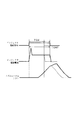
ここで、図1に示したように、エンジントルクと成り得るメイン噴射(4回噴射時第4段目噴射:本発明の当該噴射に相当する)をMaとし、このメイン噴射(Ma)の直前に先行して実施される第1パイロット噴射(4回噴射時第3段目噴射:本発明の直前噴射に相当する)をP1とし、この第1パイロット噴射(P1)の前に先行して実施される第2パイロット噴射(4回噴射時第2段目噴射:本発明の先行噴射に相当する)をP2とし、この第2パイロット噴射(P2)の前に先行して実施される第3パイロット噴射(4回噴射時第1段目噴射:本発明の先行噴射に相当する)をP3とする。
【0029】
また、図1に示したように、第3パイロット噴射(P3)におけるパイロット噴射量をQp3とし、第2パイロット噴射(P2)におけるパイロット噴射量をQp2とし、第1パイロット噴射(P1)におけるパイロット噴射量をQp1とし、メイン噴射(Ma)におけるメイン噴射量をQmとする。また、第3パイロット噴射(P3)と第2パイロット噴射(P2)との間の噴射インターバルをINTP2とし、第2パイロット噴射(P2)と第1パイロット噴射(P1)との間の噴射インターバルをINTP1とし、第1パイロット噴射(P1)とメイン噴射(Ma)との間の噴射インターバルをINTQMとする。また、図1に示したように、第3パイロット噴射(P3)と第1パイロット噴射(P1)との間の噴射インターバルをINTP31とし、第2パイロット噴射(P2)とメイン噴射(Ma)との間の噴射インターバルをINTP2Ma、第3パイロット噴射(P3)とメイン噴射(Ma)との間の噴射インターバルをINTP3Maとする。また、このときのコモンレール圧力をPc、指令噴射時期(TFIN)に対応したメイン噴射時期をTmとする。
【0030】
そして、ECU10は、エンジン1の運転状態または運転条件に応じて、マルチ噴射における各噴射量、各噴射期間、各噴射開始時期、各噴射インターバルを算出する。具体的には、エンジン回転速度(NE)と指令噴射量(QFIN)に対応した要求トータル噴射量(Qf)と予め実験等により測定して作成した特性マップ(図示せず)とからパイロット噴射量(Qp3,Qp2,Qp1)を算出するパイロット噴射量決定手段と、要求トータル噴射量(Qf)から全てのパイロット噴射量(Qp3+Qp2+Qp1)を減算してメイン噴射量(Qm)を算出するメイン噴射量決定手段と、エンジン回転速度(NE)と要求トータル噴射量(Qf)と予め実験等により測定して作成した特性マップ(図示せず)とによって最適なメイン噴射時期(Tm)を算出するメイン噴射開始時期決定手段と、エンジン回転速度(NE)と要求トータル噴射量(Qf)と予め実験等により測定して作成した特性マップ(図示せず)とによって最適なパイロット噴射開始時期を算出するパイロット噴射開始時期決定手段と、パイロット噴射量(Qp3,Qp2,Qp1)とコモンレール圧力(Pc)と予め実験等により測定して作成した特性マップ(図示せず)とから各パイロット噴射期間(TQP3,TQP2,TQP1)を算出するパイロット噴射期間決定手段と、メイン噴射量(Qm)とコモンレール圧力(Pc)と予め実験等により測定して作成した特性マップ(図示せず)とからメイン噴射期間(TQM)を算出するメイン噴射期間決定手段とを有している。
【0031】
さらに、エンジン回転速度(NE)とパイロット噴射量(Qp3,Qp2,Qp1)およびメイン噴射時期(Tm)と予め実験等により測定して作成した特性マップ(図示せず)とからマルチ噴射における第3パイロット噴射(P3)とメイン噴射(Ma)との間の無噴射間隔(噴射インターバル)、第2パイロット噴射(P2)とメイン噴射(Ma)との間の無噴射間隔(噴射インターバル)、第1パイロット噴射(P1)とメイン噴射(Ma)との間の無噴射間隔(噴射インターバル)を算出する無噴射間隔決定手段と、エンジン回転速度(NE)とパイロット噴射量(Qp3,Qp2,Qp1)と予め実験等により測定して作成した特性マップ(図示せず)とからマルチ噴射における第3パイロット噴射(P3)と第2パイロット噴射(P2)との間の無噴射間隔(噴射インターバル)、第2パイロット噴射(P2)と第1パイロット噴射(P1)との間の無噴射間隔(噴射インターバル)、第3パイロット噴射(P3)と第1パイロット噴射(P1)との間の無噴射間隔(噴射インターバル)等を算出する無噴射間隔決定手段とを有している。
【0032】
[第1実施例の制御方法]
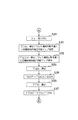
次に、本実施例のインジェクタ4のメイン噴射量制御方法を図1ないし図10に基づいて簡単に説明する。ここで、図3ないし図5はインジェクタ4のメイン噴射量制御方法を示したフローチャートである。この図3ないし図5の制御ルーチンは、イグニッションスイッチがONとなった後に、所定のタイミング毎に繰り返される。
【0033】
なお、エンジン1のk気筒(例えば#1気筒)に搭載されたインジェクタ4のメイン噴射量の演算処理は、前回サイクルでのk気筒のインジェクタ4の噴射終了後に開始しても良いし、今回サイクルでのk気筒の直前噴射気筒(k気筒が#1気筒の場合は#2気筒、k気筒が#3気筒の場合は#1気筒、k気筒が#4気筒の場合は#3気筒、k気筒が#2気筒の場合は#4気筒)の噴射終了直後に開始しても良いし、k気筒のメイン噴射の直前のパイロット噴射終了直後に開始しても良い。
【0034】
図3ないし図5の制御ルーチンに進入するタイミングになると、先ず、エンジン1のクランク角度がエンジン1のk気筒(例えば#1気筒)に搭載されたインジェクタ4のメイン噴射量の演算処理を開始する制御基準位置にあるか否かを判定する(ステップS1)。この判定結果がNOの場合には、制御基準位置に到達するまで待機する。また、ステップS1の判定結果がYESの場合には、インジェクタ4のメイン噴射量の演算処理に必要な各種センサ信号等のエンジンパラメータを取り込む。例えばクランク角度センサ34より出力されたNE信号パルスの間隔時間を計測してエンジン回転速度(NE)を取り込み、アクセル開度センサ35の検出信号に基づいてアクセル開度(ACCP)を取り込む(ステップS2)。
【0035】
次に、エンジン回転速度(NE)とアクセル開度(ACCP)とを用いて指定された特性マップ等により基本噴射量(Q)を算出する(ステップS3)。次に、基本噴射量(Q)に、各種温度(例えば燃料温度、冷却水温、大気温等)を考慮した噴射量補正量を加味して指令噴射量(QFIN)を算出する(ステップS4)。次に、指令噴射量(QFIN)からマルチ噴射時の要求トータル噴射量(Qf)を算出する(ステップS5)。次に、エンジン回転速度(NE)と要求トータル噴射量(Qf)と各種温度(例えば燃料温度、冷却水温、大気温等)を用いて指定された特性マップ等によりマルチ噴射における1噴射当たりに必要なマルチ噴射回数(N:本例ではN=4回)を算出する(ステップS6)。
【0036】
次に、エンジン回転速度(NE)と要求トータル噴射量(Qf)と各種温度(例えば燃料温度、冷却水温、大気温等)を用いて指定された特性マップ等により第3〜第1パイロット噴射量(Qp3,Qp2,Qp1)を算出する(ステップS7)。次に、要求トータル噴射量(Qf)から全パイロット噴射量(Qp3+Qp2+Qp1)を減算してメイン噴射量(Qm)を算出する(ステップS8)。次に、エンジン回転速度(NE)と要求トータル噴射量(Qf)と各種温度(例えば燃料温度、冷却水温、大気温等)を用いて指定された特性マップ等により第3〜第1パイロット噴射開始時期(Tp3,Tp2,Tp1)およびメイン噴射時期(Tm)を算出する(ステップS9)。
【0037】
次に、エンジン回転速度(NE)と要求トータル噴射量(Qf)と各種温度(例えば燃料温度、冷却水温、大気温等)を用いて指定された特性マップ等によりP3−P2間の噴射インターバル(INTP2)、P2−P1間の噴射インターバル(INTP1)、P1−Ma間の噴射インターバル(INTQM)を算出する(ステップS10)。次に、各噴射インターバル(INTP2,INTP1,INTQM)から、P3−P1間の噴射インターバル(INTP31)、P3−Ma間の噴射インターバル(INTP3Ma)、P2−Ma間の噴射インターバル(INTP2Ma)を算出する(ステップS11)。
【0038】
次に、燃料圧力センサ30の検出信号に基づいてコモンレール圧力(Pc)を取り込む(ステップS12)。次に、コモンレール圧力(Pc)とP1−Ma間の噴射インターバル(INTQM)とから、メイン噴射(Ma)の噴射開始遅れ時間補正量(2回噴射時ベース噴射開始遅れ時間補正量:TDM)を算出する(ステップS13)。この場合、パイロット噴射量(Qp1)、メイン噴射量(Qm)をも考慮して2回噴射時ベース噴射開始遅れ時間補正量(TDM)を算出するようにしても良い。
【0039】
なお、噴射開始遅れ時間補正量(TDM)は、図8に示したように、インジェクタ4の電磁弁への通電を開始してから実際に燃料が噴射されるまでの時間である。インジェクタ4は、供給される燃料圧力の作用を受けてノズルニードルがリフトして開弁する構成のものであるので、燃料圧力に応じて噴射開始遅れ時間が異なる。このため、コモンレール圧力(Pc)とP1−Ma間の噴射インターバル(INTQM)と噴射開始遅れ時間補正量(TDM)との関係を予め実験等により求めて、特性マップを作成することが望ましい。
【0040】
次に、コモンレール圧力(Pc)とP1−Ma間の噴射インターバル(INTQM)とから、メイン噴射期間補正量(2回噴射時ベース噴射期間補正量:TQDM)を算出する(ステップS14)。
この場合、パイロット噴射量(Qp1)、メイン噴射量(Qm)をも考慮して2回噴射時ベース噴射期間補正量(TQDM)を算出しても良い。
【0041】
次に、コモンレール圧力(Pc)と第3〜第1パイロット噴射量(Qp3,Qp2,Qp1)、メイン噴射量(Qm)、マルチ噴射回数のうちのいずれか少なくとも1個と上記の各噴射インターバル(INTP2,INTP1,INTP31,INTP3Ma,INTP2Ma)のうちのいずれか少なくとも1個とP1−Ma間の噴射インターバル(INTQM)および各種温度(燃料温度、冷却水温、大気温等)を用いて4回噴射時用補正係数K(Ktdm,Ktqdm)を算出する(ステップS15)。
【0042】
この場合、各パイロット噴射量(Qp3,Qp2,Qp1)、各噴射インターバル(INTP2,INTP1,INTP31,INTP3Ma,INTP2Ma)のメイン噴射(Qm)への寄与度K(Ktdm,Ktqdm)は、予め実験等により測定して作成した適合値を4回噴射時用補正係数マップ(図6参照)または演算式の形でメモリ等に記憶しておき、その4回噴射時用補正係数マップまたは演算式を参照して算出する(但し、補正係数マップ、演算式は理論値であっても良い)。
【0043】
次に、4回噴射時メイン噴射開始遅れ時間補正量(TDM4)を、下記の数1または数2の演算式により求める(ステップS16)。
【数1】

【0044】
次に、4回噴射時メイン噴射期間補正量(TQDM4)を、下記の数3または数4の演算式により求める(ステップS17)。
【数3】
【0045】
次に、コモンレール圧力(Pc)とメイン噴射量(Qm)とを用いて指定された特性マップによりメイン噴射(Ma)用のインジェクタ4の電磁弁への通電時間であるメイン噴射期間(メイン噴射指令パルス時間:TQM)を算出する(ステップS18)。次に、図7に示したように、算出されたメイン噴射期間(TQM)にメイン噴射期間補正量(TQDM4)を加算または減算して補正後メイン噴射期間(TQMF)を算出する(ステップS19)。
【0046】
次に、メイン噴射時期(Tm)とエンジン回転速度(NE)とコモンレール圧力(Pc)とを用いてメイン噴射開始時期(TTM)を算出する(ステップS20)。次に、図8に示したように、実噴射時期をメイン噴射時期(Tm)とするために算出されたメイン噴射開始時期(TTM)に対し、噴射開始遅れ時間補正量(TDM4)を加算または減算して補正後メイン噴射時期(TTMF)を算出する(ステップS21)。
【0047】
次に、制御基準位置からの、クランク角度センサ34より出力されたNE信号パルスのパルス数をカウントし、カウントしたパルス数がメイン噴射時期パルス数(CNECAMF)となったか否かを判定する(ステップS22)。この判定結果がNOの場合には、カウントしたパルス数がメイン噴射時期パルス数(CNECAMF)となるまで待機する。
【0048】
また、ステップS22の判定結果がYESの場合には、カウントしたパルス数がメイン噴射時期パルス数(CNECAMF)となってから補正後メイン噴射時期(TTMF)が経過したか否かを判定する(ステップS23)。この判定結果がNOの場合には、補正後メイン噴射時期(TTMF)となるまで待機する。
また、ステップS23の判定結果がYESの場合には、インジェクタ4の電磁弁への通電を開始(インジェクタ駆動指令をON)する(ステップS24)。なお、噴射開始時期は必ずしもパルス基準でなくても良い。TTMFは、クランクシャフトの絶対角度(例えばBTDC=10°CA等)であっても良い。この場合、CNECAMFは考慮することなく、クランク角度または時間TTMF経過後に噴射開始するようにすれば良い。
【0049】
これにより、インジェクタ4の電磁弁への通電開始時刻、つまりパルス状のインジェクタ駆動電流(TQパルス)の立ち上がり時刻から所定の噴射開始遅れ時間(TDM=TDM4)が経過した後に、インジェクタ4のノズルニードルが燃料圧力を受けて開弁方向にリフトする。よって、インジェクタ4の先端に形成された複数個の噴射孔が開放されるため、エンジン1のk気筒(例えば#1気筒)内への燃料噴射が開始される。つまりエンジン1のk気筒(例えば#1気筒)のメイン噴射が開始される。
【0050】
次に、インジェクタ4の電磁弁への通電を開始してから補正後メイン噴射期間(TQMF)が経過したか否かを判定する(ステップS25)。この判定結果がNOの場合には、補正後メイン噴射期間(TQMF)が経過するまで待機する。
また、ステップS25の判定結果がYESの場合には、インジェクタ4の電磁弁への通電を終了(インジェクタ駆動指令をOFF)する(ステップS26)。その後に、図3ないし図5の制御ルーチンを抜ける。
【0051】
これにより、インジェクタ4の電磁弁への通電を終了してから所定の噴射終了遅れ時間経過後に、インジェクタ4のノズルニードルがスプリング等の付勢手段の付勢力を受けて閉弁方向に移動して弁座に着座する。よって、インジェクタ4の先端に形成された複数個の噴射孔が閉塞されるため、エンジン1のk気筒(例えば#1気筒)内への燃料噴射が終了する。つまりエンジン1のk気筒(例えば#1気筒)のメイン噴射が終了する。
【0052】
[第1実施例の特徴]
次に、本実施例のインジェクタ4のメイン噴射量制御方法を図1ないし図10に基づいて簡単に説明する。
【0053】
今回、インターバル依存性の補正パラメータとして、メイン噴射(Ma)の直前に先行して実施される第1パイロット噴射(P1)のパイロット噴射量(Qp1)、およびP1−Ma間の噴射インターバル(INTQM)だけでなく、第1パイロット噴射(P1)の前に先行して実施される第2パイロット噴射量(P2)のパイロット噴射量(Qp2)、およびP2−P1間の噴射インターバル(INTP1)、更にはその前の前の第3パイロット噴射(P3)のパイロット噴射量(Qp3)、およびP3−P2間の噴射インターバル(INTP2)等をも考慮すると言うことは下記の通りである。なお、図9の説明図中の高圧配管内圧力とは、インジェクタ4の電磁弁のバルブ近傍の燃料圧力を表している。
【0054】
図9の説明図に示したように、例えば4回噴射時(メイン噴射前にパイロット噴射3回)のメイン噴射を考えると、従来の2回噴射時(メイン噴射前にパイロット噴射1回)の高圧配管29内の圧力脈動に対し、4回噴射時の高圧配管29内の圧力脈動は、第1パイロット噴射よりも前の2回のパイロット噴射(第3パイロット噴射、第2パイロット噴射)の影響を受けて、周期(B−B’)、振幅(A−A’)が変化する。ここで、近似的に2回噴射時の高圧配管29内の圧力脈動は、下記の数5の演算式で表される。
【数5】
【0055】
次に、4回噴射時の高圧配管29内圧力の挙動を簡易的に表すと、下記の数6の演算式となる。
【数6】
なお、α、βはコモンレール圧力(Pc)と各パイロット噴射量(Qp3,Qp2)のうちいずれか少なくとも1個とパイロット噴射量(Qp1)、メイン噴射量(Qm)、各噴射インターバル(INTP2,INTP31,INTP3Ma,INTP2Ma)のうちいずれか少なくとも1個とに関連して求まる値である。
【0056】
すなわち、図10の説明図に示したように、指令噴射量(目標噴射量:QFIN)に対する噴射量のずれ(Qd4)が求めるべき補正値となり、2回噴射時の補正値(Qd2)に対し、Qd4=f(Qd2)となり、更なる補正が必要となる。但し、関数f(Qd2)は、上記の数6の演算式を応用した理論式だけでなく、予め実験等により測定して作成した実際の適合値でも十分である。
【0057】
[第1実施例の効果]
ここで、3回以上の多段噴射(第2パイロット噴射−第1パイロット噴射−メイン噴射または第3パイロット噴射−第2パイロット噴射−第1パイロット噴射−メイン噴射)を行なう場合、従来技術では、当該噴射の直前に先行して実施される直前噴射と当該噴射との間の噴射インターバル(例えば第2パイロット噴射と第1パイロット噴射との間の噴射インターバル、第1パイロット噴射とメイン噴射との間の噴射インターバル)とその時のコモンレール圧力(Pc)、直前噴射(第1パイロット噴射に対する第2パイロット噴射、メイン噴射に対する第1パイロット噴射等)の噴射量を補正パラメータとしてインターバルの依存性を補正していた。
【0058】
しかし、本実施例のコモンレール式燃料噴射システムでは、更にインターバル依存性の補正パラメータとしてメイン噴射(Ma)の前の第1パイロット噴射(P1)のパイロット噴射量(Qp1)および噴射インターバル(INTQM)だけでなく、第1パイロット噴射(P1)の更に前(例えばメイン噴射に対する第2パイロット噴射や第3パイロット噴射等)のパイロット噴射量(Qp3,Qp2)および各噴射インターバル(INTP31,INTP3Ma,INTP2Ma,INTP2,INTP1)をも補正パラメータとして持つようにしている。
【0059】
すなわち、メイン噴射(Ma)の直前に先行して1回のパイロット噴射を実施する、通常の2回噴射時のメイン噴射開始時期補正および通常の2回噴射時のメイン噴射期間補正に対して、メイン噴射(Ma)の直前に先行して実施される第1パイロット噴射(P1)のパイロット噴射量(Qp1)および噴射インターバル(INTQM)だけでなく、その第1パイロット噴射(P1)の前に先行して実施される第2パイロット噴射(P2)のパイロット噴射量(Qp2)および各噴射インターバル(INTP1,INTP2Ma)、更にその第2パイロット噴射(P2)の前に先行して実施される第3パイロット噴射(P3)のパイロット噴射量(Qp3)および各噴射インターバル(INTP2,INTP3Ma)をも考慮したメイン噴射開始時期補正およびメイン噴射期間補正を実施することで、3回以上のマルチ噴射時(本例では4回噴射時)のコモンレール2と当該インジェクタ4間の高圧配管29内の圧力脈動の影響による当該噴射(例えばメイン噴射)の噴射量脈動を防止することができる。
【0060】
[第2実施例]
図11ないし図14は本発明の第2実施例を示したもので、図11はインジェクタ4のメイン噴射量制御方法を示したフローチャートである。ここで、図11の制御ルーチンは、図3の制御ルーチンのステップS11の演算処理が終了した後に実行され、各種の演算処理や制御処理を実施した後に、図5の制御ルーチンのステップS22の処理に進む。なお、図3および図5の制御ルーチンは、第1実施例と同一処理のため、説明を省略する。
【0061】
図3の制御ルーチンのステップS11の演算処理を実行した後に、燃料圧力センサ30の検出信号に基づいてコモンレール圧力(Pc)を取り込む(ステップS31)。次に、コモンレール圧力(Pc)とP1−Ma間の噴射インターバル(INTQM)と予め設定された4回噴射時用補正係数または補正量マップを検索して、メイン噴射(Qm)の噴射開始遅れ時間補正量(TDM)を算出する(ステップS32)。
【0062】
この場合、検索する4回噴射時用補正係数または補正量マップは、4回噴射時第4段目噴射用補正係数または補正量マップ(図12参照)であり、別途3回噴射時第3段目噴射用補正係数または補正量マップまたは2回噴射時第2段目噴射用補正係数または補正量マップも準備しておく。また、第2パイロット噴射(P2)や第1パイロット噴射(P1)の噴射開始遅れ時間補正量(TDM)を算出するために、別途4回噴射時第2段目噴射用補正係数または補正量マップ、4回噴射時第3段目噴射用補正係数または補正量マップ、または3回噴射時第2段目噴射用補正係数または補正量マップも準備しておくことが望ましい(図13参照)。
【0063】
但し、これらの補正係数または補正量マップは、各パイロット噴射量(Qp3,Qp2,Qp1)、メイン噴射量(Qm)、各噴射インターバル(INTP1,INTP31,INTP3Ma,INTP2Ma)の影響を考慮して予め適合を行なう必要がある(図13参照)。なお、噴射インターバル(INTP2)、各種温度(燃料温度、冷却水温、大気温等)も考慮して、メイン噴射(Ma)の噴射開始遅れ時間補正量(TDM)を算出するようにしても良い。
【0064】
次に、コモンレール圧力(Pc)と第1パイロット噴射(P1)とメイン噴射(Ma)との間の噴射インターバル(INTQM)と予め設定された4回噴射時用補正係数または補正量マップを検索して、メイン噴射期間補正量(TQDM)を算出する(ステップS33)。
【0065】
この場合、検索する4回噴射時用補正係数または補正量マップは、図12に示したような4回噴射時第4段目噴射用補正係数または補正量マップであり、別途3回噴射時第3段目噴射用補正係数または補正量マップまたは2回噴射時第2段目噴射用補正係数または補正量マップも準備しておく。また、第2パイロット噴射(P2)や第1パイロット噴射(P1)の噴射開始遅れ時間補正量(TDM)を算出するために、別途4回噴射時第2段目噴射用補正係数または補正量マップ、4回噴射時第3段目噴射用補正係数または補正量マップ、または3回噴射時第2段目噴射用補正係数または補正量マップも準備しておくことが望ましい。
【0066】
但し、これらの補正係数または補正量マップは、各パイロット噴射量(Qp3,Qp2,Qp1)、メイン噴射量(Qm)、各噴射インターバル(INTP1,INTP31,INTP3Ma,INTP2Ma)の影響を考慮して予め適合を行なう必要がある。なお、噴射インターバル(INTP2)、各種温度(燃料温度、冷却水温、大気温等)も考慮して、メイン噴射期間補正量(TQDM)を算出するようにしても良い。
【0067】
次に、コモンレール圧力(Pc)とメイン噴射量(Qm)とを用いて指定された特性マップによりメイン噴射(Ma)用のインジェクタ4の電磁弁への通電時間であるメイン噴射期間(メイン噴射指令パルス時間:TQM)を算出する(ステップS34)。次に、算出されたメイン噴射期間(TQM)にメイン噴射期間補正量(TQDM)を加算または減算して補正後メイン噴射期間(TQMF)を算出する(ステップS35)。
【0068】
次に、メイン噴射時期(Tm)とエンジン回転速度(NE)とコモンレール圧力(Pc)とを用いてメイン噴射開始時期(TTM)を算出する(ステップS36)。次に、実噴射時期をメイン噴射時期(Tm)とするために算出されたメイン噴射開始時期(TTM)に対し、噴射開始遅れ時間補正量(TDM)を加算または減算して補正後メイン噴射時期(TTMF)を算出する(ステップS37)。その後に、図5の制御ルーチンのステップS22以降の制御処理を実行する。
【0069】
また、例えばエンジン1の運転状態または運転条件が変更されることによって、マルチ噴射回数が4回噴射から3回噴射に切り替わった場合には、図14に示したように、それまでの4回噴射時に第2パイロット噴射(P2)の噴射開始遅れ時間補正および噴射期間補正に用いていた4回噴射時用補正係数または補正量マップまたは噴射インターバル(INTP2)を、3回噴射時の第1パイロット噴射(P1)の噴射開始遅れ時間補正および噴射期間補正に転用しても構わない。
【0070】
これは、4回噴射の場合、第2パイロット噴射(P2)が先頭から2段目の噴射であり、3回噴射の場合、第1パイロット噴射(P1)が先頭から2段目の噴射となり、且つパイロット噴射量(Qp2)とパイロット噴射量(Qp1)とは共に微少噴射量であり、その影響は同等と考えられるためである。また、4回噴射時に第1パイロット噴射(P1)の噴射開始遅れ時間補正および噴射期間補正に用いていた4回噴射時用補正係数または補正量マップを、3回噴射時にメイン噴射(Ma)の噴射開始遅れ時間補正および噴射期間補正に用いる3回噴射時用補正係数または補正量マップに転用しても良い。
【0071】
[変形例]
本実施例では、本発明をパイロット学習制御装置に適用した例を示したが、本発明をコモンレールを備えず、電子制御方式の分配型燃料噴射ポンプまたは電子制御方式の列型燃料噴射ポンプ等を備えた内燃機関用噴射量制御装置に適用しても良い。また、本実施例では、電磁式燃料噴射弁よりなるインジェクタ4を用いた例を説明したが、圧電方式の燃料噴射弁よりなるインジェクタを用いても良い。また、メイン噴射の前に先行して実施されるパイロット噴射(プレ噴射とも言う)の回数は、1回以上任意に設定しても良く、また、メイン噴射の後に実施されるアフター噴射(ポスト噴射とも言う)の回数も、0回または1回以上任意に設定しても良い。
【0072】
本実施例では、図1に示したように、各噴射インターバル(INTP2,INTP1,INTQM,INTP31,INTP2Ma,INTP3Ma)を、パイロット噴射開始時期とメイン噴射開始時期とのスタートtoスタートとしたが、各噴射インターバル(INTP2,INTP1,INTQM,INTP31,INTP2Ma,INTP3Ma)を、パイロット噴射終了時期とメイン噴射開始時期とのエンドtoスタートとパイロット噴射期間とに分離しても良い。
【図面の簡単な説明】
【図1】各噴射インターバルを算出するための図である(第1実施例)。
【図2】コモンレール式燃料噴射システムの全体構成を示した概略図である(第1実施例)。
【図3】インジェクタのメイン噴射量制御方法を示したフローチャートである(第1実施例)。
【図4】インジェクタのメイン噴射量制御方法を示したフローチャートである(第1実施例)。
【図5】インジェクタのメイン噴射量制御方法を示したフローチャートである(第1実施例)。
【図6】4回噴射時用補正係数マップを示した図である(第1実施例)。
【図7】補正後メイン噴射期間を算出するための図である(第1実施例)。
【図8】補正後メイン噴射時期を算出するための図である(第1実施例)。
【図9】4回噴射時の高圧配管内の圧力脈動を示した説明図である(第1実施例)。
【図10】指令噴射量に対する噴射量のずれが補正値であることを示した説明図である(第1実施例)。
【図11】インジェクタのメイン噴射量制御方法を示したフローチャートである(第2実施例)。
【図12】4回噴射時用補正係数または補正量マップを示した図である(第2実施例)。
【図13】(a)は4回噴射時用補正係数または補正量マップを示した説明図で、(b)は3回噴射時用補正係数または補正量マップを示した説明図で、(c)は2回噴射時用補正係数または補正量マップを示した説明図である(第2実施例)。
【図14】(a)は4回噴射時用補正係数または補正量マップを示した説明図で、(b)は3回噴射時用補正係数または補正量マップとして(a)を転用した場合を示した説明図である(第2実施例)。
【図15】インターバルに対する高圧配管内の圧力脈動とメイン噴射量特性を示した説明図である(従来の技術)。
【図16】3回噴射時の高圧配管内の圧力脈動を示した説明図である(従来の技術)。
【符号の説明】
1 エンジン(内燃機関)
2 コモンレール(蓄圧容器)
3 サプライポンプ(燃料供給ポンプ)
4 インジェクタ(電磁式燃料噴射弁)
10 ECU(噴射量補正手段)
29 高圧配管(噴射鋼管)[0001]
BACKGROUND OF THE INVENTION
In the present invention, the pilot solenoid valve mounted corresponding to each cylinder of the internal combustion engine is driven a plurality of times during one combustion stroke of the internal combustion engine, so that two or more pilots are performed before the main injection. TECHNICAL FIELD The present invention relates to an injection rate control device for an internal combustion engine that performs injection, and in particular, when the number of injections per injection in multistage injection is three or more, as an interval-dependent correction parameter, the injection amount of preceding injection further before the immediately preceding injection The present invention also relates to an injection rate control device for an internal combustion engine that performs injection start timing correction or injection period correction of the injection in consideration of an interval between preceding injection and immediately preceding injection.
[0002]
[Prior art]
2. Description of the Related Art Conventionally, an accumulator fuel injection system that supplies high pressure fuel accumulated in a common rail into each cylinder of an engine is known as a fuel injection device for a diesel engine. In such an accumulator fuel injection system, the main injection (which can be engine torque) is performed for the purpose of reducing combustion noise and engine vibration and improving exhaust gas performance by performing stable combustion from the start of main injection. Prior to the main injection, a plurality of small prior injections (pilot injections) are performed. Here, normally, the injection amount control to each cylinder of the engine is performed according to the command injection period calculated from the command injection amount set according to the operating state or operating condition of the engine and the common rail pressure detected by a sensor or the like. This is implemented by determining the injection amount command value applied to the solenoid valve of the injector.
[0003]
Here, in multistage injection in which pilot injection is performed as described above, there is no difference between pilot injection and main injection due to pressure pulsation in the common rail caused by pilot injection and pressure pulsation in the high-pressure pipe (injection steel pipe) between the injectors. There is a problem that the main injection amount pulsates depending on the injection interval (see FIG. 15). In response to such a problem, Japanese Patent Laid-Open No. 6-101552 and Japanese Patent Laid-Open No. 10-266888 correct the main injection amount according to the injection interval (pilot interval) between the pilot injection and the main injection. An injector injection amount control method as described above has been proposed.
[0004]
[Problems to be solved by the invention]
However, at the time of three injections such as the second pilot injection-first pilot injection-main injection, the pressure pulsation in the high-pressure piping at the time of main injection is performed prior to the first pilot injection. Under the influence of pilot injection, pulsations (changes in cycle and amplitude) that are different from those at the time of two injections such as first pilot injection-main injection occur. For this reason, in order to accurately correct the main injection amount at the time of the third injection, not only the influence of the first pilot injection performed immediately before the main injection but also the first pilot injection before the first pilot injection. It has been found that it is desirable to correct the main injection start timing and the main injection period in consideration of the effects of the two pilot injections, or the injection quantity and the injection interval before that (see FIG. 16).
[0005]
OBJECT OF THE INVENTION
The object of the present invention is to reduce the injection amount of the preceding injection performed prior to the immediately preceding injection and the no-injection interval between the immediately preceding injection and the preceding injection when the number of injections in the multistage injection is 3 or more. In view of this, an internal combustion engine capable of preventing the injection amount pulsation of the injection due to the influence of the pressure pulsation in the injector and the high-pressure pipe by performing the injection start timing correction or the injection period correction of the injection. An object of the present invention is to provide an engine injection rate control device.
[0006]
[Means for Solving the Problems]
According to the first aspect of the present invention, when the number of injections in the multistage injection is 3 or more, the injection amount of the immediately preceding injection performed immediately before the injection, and between the injection and the immediately preceding injection Use not only the no-injection interval, but also the injection amount of the preceding injection performed prior to the immediately preceding injection, and the no-injection interval between the immediately preceding injection and the preceding injectionAlso use the injection interval between the preceding injection and the injectionIn consideration of the influence of the pressure pulsation in the common rail generated in the immediately preceding injection and the preceding injection on the injection, the injection start time correction of the injection or the injection period correction of the injection is performed, so that the injector It is possible to prevent the injection amount pulsation of the injection due to the influence of the pressure pulsation in the internal and high pressure pipes.
[0007]
Claim2According to the invention, the multi-injection that performs two or more pilot injections before the main injection may be used as the multistage injection, or the multi-injection that performs two or more after injections after the main injection is used. Alternatively, a multi-injection in which one or more pilot injections are performed before the main injection and one or more after injections are performed after the main injection may be used.
Claim3When the number of injections in the multistage injection is set to 3 and the injection is the main injection, the immediately preceding injection is the first pilot injection and the preceding injection is the second pilot injection. It is characterized by becoming. Claims4When the number of injections in the multistage injection is set to four, and the injection is the main injection, the immediately preceding injection is the first pilot injection and the preceding injection is the third and second. It is characterized by pilot injection.
[0008]
Claim5According to the invention described in the above, not only the injection amount of the first pilot injection performed immediately before the main injection and the non-injection interval between the main injection and the first pilot injection, but also the injection in the multistage injection The number of times, the injection pressure of the fuel injected into the cylinder of the internal combustion engine, the injection amount of the third pilot injection, the injection amount of the second pilot injection, and the non-injection interval between the second pilot injection and the first pilot injection , No-injection interval between the third pilot injection and the second pilot injection, no-injection interval between the third pilot injection and the first pilot injection, no-injection interval between the second pilot injection and the main injection, Considering at least one of the non-injection intervals between the third pilot injection and the main injection, the injection start timing correction of the main injection or the injection period correction of the main injection is performed. By, it is possible to prevent the injection amount pulsation of the main injection due to the influence of the pressure pulsation in the injector and the high-pressure pipe.
[0009]
DETAILED DESCRIPTION OF THE INVENTION
DESCRIPTION OF THE PREFERRED EMBODIMENTS Embodiments of the invention will be described based on examples with reference to the drawings.
[Configuration of the first embodiment]
FIG. 1 to FIG. 10 show a first embodiment of the present invention, and FIG. 2 shows the overall configuration of a common rail fuel injection system.
[0010]
The common rail fuel injection system according to the present embodiment includes a
[0011]
The intake port of each cylinder (cylinder) of the
[0012]
Here, the exhaust gas combusted in the cylinder during the operation of the
[0013]
An intake throttle valve (throttle valve) 19 for adjusting the amount of intake air (intake amount) supplied to the
[0014]
Further, an exhaust
[0015]
The high pressure fuel corresponding to the fuel injection pressure needs to be continuously stored in the
[0016]
The
[0017]
The plurality of injectors 4 are attached to the cylinder block of the engine 1 (corresponding to each
[0018]
Therefore, fuel injection from the injector 4 for each cylinder into each cylinder of the
[0019]
The
[0020]
Here, the cylinder discriminating means of the present embodiment includes a signal rotor (for example, a rotating body that rotates once while the crankshaft rotates twice) 31 corresponding to the camshaft of the
[0021]
Then, the
[0022]
More preferably, for the purpose of improving the control accuracy of the fuel injection amount, the fuel pressure in the common rail 2 (common rail pressure: Pc) detected by the
[0023]
The
[0024]
Here, in the present embodiment, the basic injection amount (Q) using the rotational speed detecting means such as the
[0025]
The
[0026]
Here, in the common rail fuel injection system of the present embodiment, one cycle of the engine 1 (1 stroke: intake stroke-compression stroke-expansion stroke (explosion stroke)) in the injector 4 of the specific cylinder (k cylinder) of the engine 1- During the exhaust stroke), that is, while the crankshaft of the
[0027]
In the present embodiment, the main injection period correction and the main injection start timing correction at the time of four injections where the number of multi-injections is set to four will be described as an example. Note that the second and first pilot injections (P2, P1) as the next injections performed after the third and second pilot injections (P3, P2) as the preceding injections, or the pilot injections as the preceding injections. As pre-injection as the next injection, or after injection as the next injection after the main injection (Ma) as the preceding injection, or as the next injection to be executed after the after injection as the preceding injection The same applies to the injection amount correction (at least one of the injection period and the injection start timing) in the post injection.
[0028]
Here, as shown in FIG. 1, the main injection (fourth-stage injection at the time of four injections: corresponding to the injection of the present invention) that can be engine torque is Ma, and immediately before the main injection (Ma). The first pilot injection (third injection at the time of four injections: corresponding to the immediately preceding injection of the present invention) is set as P1, and is executed before the first pilot injection (P1). The second pilot injection (second injection at the time of four injections: corresponding to the preceding injection of the present invention) is P2, and the third pilot that is performed prior to the second pilot injection (P2) The injection (first-stage injection at the time of four injections: corresponding to the preceding injection of the present invention) is P3.
[0029]
Further, as shown in FIG. 1, the pilot injection amount in the third pilot injection (P3) is Qp3, the pilot injection amount in the second pilot injection (P2) is Qp2, and the pilot injection in the first pilot injection (P1). The amount is Qp1, and the main injection amount in the main injection (Ma) is Qm. Further, the injection interval between the third pilot injection (P3) and the second pilot injection (P2) is INTP2, and the injection interval between the second pilot injection (P2) and the first pilot injection (P1) is INTP1. And the injection interval between the first pilot injection (P1) and the main injection (Ma) is INTQM. Further, as shown in FIG. 1, the injection interval between the third pilot injection (P3) and the first pilot injection (P1) is INTP31, and the second pilot injection (P2) and the main injection (Ma) The injection interval between them is INTP2Ma, and the injection interval between the third pilot injection (P3) and the main injection (Ma) is INTP3Ma. The common rail pressure at this time is Pc, and the main injection timing corresponding to the command injection timing (TFIN) is Tm.
[0030]
Then, the
[0031]
Further, the third speed in the multi-injection is determined based on the engine speed (NE), the pilot injection amount (Qp3, Qp2, Qp1), the main injection timing (Tm), and a characteristic map (not shown) created by measurement in advance. No injection interval (injection interval) between pilot injection (P3) and main injection (Ma), no injection interval (injection interval) between second pilot injection (P2) and main injection (Ma), first Non-injection interval determining means for calculating a non-injection interval (injection interval) between pilot injection (P1) and main injection (Ma), engine speed (NE) and pilot injection amount (Qp3, Qp2, Qp1) The third pilot injection (P3) and the second pilot injection in the multi-injection from a characteristic map (not shown) created by measurement in advance through experiments or the like No injection interval (injection interval) between P2), No injection interval (injection interval) between second pilot injection (P2) and first pilot injection (P1), Third pilot injection (P3) and first And a non-injection interval determining means for calculating a non-injection interval (injection interval) between one pilot injection (P1) and the like.
[0032]
[Control Method of First Embodiment]
Next, a method for controlling the main injection amount of the injector 4 according to this embodiment will be briefly described with reference to FIGS. Here, FIG. 3 to FIG. 5 are flowcharts showing the main injection amount control method of the injector 4. The control routines of FIGS. 3 to 5 are repeated at predetermined timings after the ignition switch is turned on.
[0033]
The calculation process of the main injection amount of the injector 4 mounted on the k cylinder (for example, # 1 cylinder) of the
[0034]
When the timing for entering the control routine of FIGS. 3 to 5 is reached, first, calculation processing of the main injection amount of the injector 4 in which the crank angle of the
[0035]
Next, the basic injection amount (Q) is calculated by a characteristic map or the like designated using the engine speed (NE) and the accelerator opening (ACCP) (step S3). Next, a command injection amount (QFIN) is calculated by adding an injection amount correction amount considering various temperatures (for example, fuel temperature, cooling water temperature, atmospheric temperature, etc.) to the basic injection amount (Q) (step S4). Next, a required total injection amount (Qf) at the time of multi-injection is calculated from the command injection amount (QFIN) (step S5). Next, it is necessary for each injection in the multi-injection according to the characteristic map specified using the engine speed (NE), the required total injection amount (Qf), and various temperatures (for example, fuel temperature, cooling water temperature, atmospheric temperature, etc.) Multi-injection count (N: N = 4 in this example) is calculated (step S6).
[0036]
Next, the third to first pilot injection amounts are determined by a characteristic map or the like specified using the engine speed (NE), the required total injection amount (Qf), and various temperatures (for example, fuel temperature, cooling water temperature, atmospheric temperature, etc.). (Qp3, Qp2, Qp1) is calculated (step S7). Next, the main injection amount (Qm) is calculated by subtracting the total pilot injection amount (Qp3 + Qp2 + Qp1) from the required total injection amount (Qf) (step S8). Next, the third to first pilot injections are started by a characteristic map designated by using the engine speed (NE), the required total injection amount (Qf), and various temperatures (for example, fuel temperature, cooling water temperature, atmospheric temperature, etc.) Timing (Tp3, Tp2, Tp1) and main injection timing (Tm) are calculated (step S9).
[0037]
Next, the injection interval between P3 and P2 (P3 and P2) according to the characteristic map specified using the engine speed (NE), the required total injection amount (Qf), and various temperatures (for example, fuel temperature, cooling water temperature, atmospheric temperature, etc.) INTP2), an injection interval (INTP1) between P2 and P1, and an injection interval (INTQM) between P1 and Ma are calculated (step S10). Next, from each injection interval (INTP2, INTP1, INTQM), an injection interval (INTP31) between P3 and P1, an injection interval between P3 and Ma (INTP3Ma), and an injection interval between P2 and Ma (INTP2Ma) are calculated. (Step S11).
[0038]
Next, the common rail pressure (Pc) is taken in based on the detection signal of the fuel pressure sensor 30 (step S12). Next, from the common rail pressure (Pc) and the injection interval (INTQM) between P1 and Ma, the injection start delay time correction amount (base injection start delay time correction amount during two injections: TDM) of the main injection (Ma) is calculated. Calculate (step S13). In this case, the base injection start delay time correction amount (TDM) for the two-time injection may be calculated in consideration of the pilot injection amount (Qp1) and the main injection amount (Qm).
[0039]
The injection start delay time correction amount (TDM) is the time from the start of energization to the solenoid valve of the injector 4 until the fuel is actually injected, as shown in FIG. The injector 4 has a configuration in which the nozzle needle lifts and opens under the action of the supplied fuel pressure, and therefore the injection start delay time varies depending on the fuel pressure. For this reason, it is desirable to obtain a relationship between the common rail pressure (Pc), the injection interval (INTQM) between P1 and Ma, and the injection start delay time correction amount (TDM) in advance through experiments or the like to create a characteristic map.
[0040]
Next, a main injection period correction amount (second injection base injection period correction amount: TQDM) is calculated from the common rail pressure (Pc) and the injection interval (INTQM) between P1 and Ma (step S14).
In this case, the base injection period correction amount (TQDM) for the two-time injection may be calculated in consideration of the pilot injection amount (Qp1) and the main injection amount (Qm).
[0041]
Next, at least one of the common rail pressure (Pc), the third to first pilot injection amounts (Qp3, Qp2, Qp1), the main injection amount (Qm), and the number of multi-injections, and each injection interval ( At the time of four injections using an injection interval (INTQM) between at least one of INTP2, INTP1, INTP31, INTP3Ma, INTP2Ma) and P1-Ma and various temperatures (fuel temperature, cooling water temperature, atmospheric temperature, etc.) Correction coefficient K (Ktdm, Ktqdm) is calculated (step S15).
[0042]
In this case, the contribution degree K (Ktdm, Ktqdm) of each pilot injection amount (Qp3, Qp2, Qp1) and each injection interval (INTP2, INTP1, INTP31, INTP3Ma, INTP2Ma) to the main injection (Qm) is experimentally performed in advance. The calibration value created by measuring in accordance with the above is stored in a memory or the like in the form of a correction coefficient map for four injections (see FIG. 6) or an arithmetic expression, and the correction coefficient map for four injections or the arithmetic expression is referenced. (However, the correction coefficient map and the arithmetic expression may be theoretical values).
[0043]
Next, the main injection start delay time correction amount (TDM4) at the time of four injections is obtained by the
[Expression 1]
[0044]
Next, the main injection period correction amount (TQDM4) at the time of four injections is obtained by the following equation (3) or (4) (step S17).
[Equation 3]
[0045]
Next, the main injection period (main injection command) which is the energization time to the solenoid valve of the injector 4 for main injection (Ma) according to the characteristic map specified using the common rail pressure (Pc) and the main injection amount (Qm). (Pulse time: TQM) is calculated (step S18). Next, as shown in FIG. 7, the corrected main injection period (TQMF) is calculated by adding or subtracting the main injection period correction amount (TQDM4) to the calculated main injection period (TQM) (step S19). .
[0046]
Next, the main injection start timing (TTM) is calculated using the main injection timing (Tm), the engine speed (NE), and the common rail pressure (Pc) (step S20). Next, as shown in FIG. 8, the injection start delay time correction amount (TDM4) is added to the main injection start timing (TTM) calculated to set the actual injection timing as the main injection timing (Tm). The corrected main injection timing (TTMF) is calculated by subtraction (step S21).
[0047]
Next, the number of NE signal pulses output from the
[0048]
If the determination result in step S22 is YES, it is determined whether or not the corrected main injection timing (TTMF) has elapsed after the counted number of pulses has reached the main injection timing pulse number (CNECAMF) (step S22). S23). When the determination result is NO, the process waits until the corrected main injection timing (TTMF) is reached.
If the determination result in step S23 is YES, energization of the solenoid valve of the injector 4 is started (injector drive command is turned on) (step S24). The injection start timing is not necessarily based on the pulse. TTMF may be an absolute angle of the crankshaft (for example, BTDC = 10 ° CA). In this case, the injection may be started after the crank angle or time TTMF has elapsed without considering CNECAMMF.
[0049]
Thereby, after a predetermined injection start delay time (TDM = TDM4) has elapsed from the start time of energization of the solenoid valve of the injector 4, that is, the rise time of the pulsed injector drive current (TQ pulse), the nozzle needle of the injector 4 Receives fuel pressure and lifts in the valve opening direction. Therefore, since the plurality of injection holes formed at the tip of the injector 4 are opened, fuel injection into the k cylinder (for example, # 1 cylinder) of the
[0050]
Next, it is determined whether or not the corrected main injection period (TQMF) has elapsed since the start of energization of the solenoid valve of the injector 4 (step S25). When the determination result is NO, the process waits until the corrected main injection period (TQMF) elapses.
On the other hand, if the decision result in the step S25 is YES, the energization to the solenoid valve of the injector 4 is ended (the injector drive command is turned off) (step S26). Thereafter, the control routine of FIGS. 3 to 5 is exited.
[0051]
As a result, the nozzle needle of the injector 4 receives the urging force of the urging means such as a spring and moves in the valve closing direction after a predetermined injection end delay time elapses after the energization of the solenoid valve of the injector 4 is terminated. Sit on the valve seat. Therefore, since the plurality of injection holes formed at the tip of the injector 4 are closed, fuel injection into the k cylinder (for example, # 1 cylinder) of the
[0052]
[Features of the first embodiment]
Next, a method for controlling the main injection amount of the injector 4 according to this embodiment will be briefly described with reference to FIGS.
[0053]
This time, as interval-dependent correction parameters, the pilot injection amount (Qp1) of the first pilot injection (P1) performed immediately before the main injection (Ma), and the injection interval (INTQM) between P1 and Ma As well as the pilot injection amount (Qp2) of the second pilot injection amount (P2) performed prior to the first pilot injection (P1), and the injection interval (INTP1) between P2 and P1, and It is as follows that the pilot injection amount (Qp3) of the previous third pilot injection (P3) and the injection interval (INTP2) between P3-P2 and the like are also taken into consideration. 9 represents the fuel pressure in the vicinity of the valve of the solenoid valve of the injector 4.
[0054]
As shown in the explanatory diagram of FIG. 9, for example, when considering the main injection at the time of four injections (three pilot injections before the main injection), the conventional two injections (one pilot injection before the main injection) are performed. The pressure pulsation in the high-pressure pipe 29 during the four-time injection is affected by the two pilot injections (third pilot injection and second pilot injection) before the first pilot injection with respect to the pressure pulsation in the high-pressure pipe 29. In response, the cycle (BB ′) and amplitude (AA ′) change. Here, the pressure pulsation in the high-pressure pipe 29 at the time of approximately two injections is approximately expressed by the following equation (5).
[Equation 5]
[0055]
Next, when the behavior of the pressure in the high-pressure pipe 29 at the time of four injections is simply expressed, the following expression 6 is obtained.
[Formula 6]
Α and β are at least one of the common rail pressure (Pc) and each pilot injection amount (Qp3, Qp2), the pilot injection amount (Qp1), the main injection amount (Qm), and each injection interval (INTP2, INTP31). , INTP3Ma, and INTP2Ma), a value obtained in association with at least one of them.
[0056]
That is, as shown in the explanatory diagram of FIG. 10, the deviation (Qd4) of the injection amount with respect to the command injection amount (target injection amount: QFIN) is a correction value to be obtained, and is the correction value (Qd2) for the second injection. Qd4 = f (Qd2), and further correction is required. However, the function f (Qd2) is not limited to a theoretical formula obtained by applying the arithmetic expression of Equation 6 above, but may be an actual fit value created by measurement in advance through experiments or the like.
[0057]
[Effect of the first embodiment]
Here, when performing multi-stage injection three times or more (second pilot injection-first pilot injection-main injection or third pilot injection-second pilot injection-first pilot injection-main injection), An injection interval between the immediately preceding injection and the injection performed immediately before the injection (for example, an injection interval between the second pilot injection and the first pilot injection, between the first pilot injection and the main injection) The interval dependence was corrected using the injection amount of the injection interval), the common rail pressure (Pc) at that time, and the injection amount of the immediately preceding injection (second pilot injection for the first pilot injection, first pilot injection for the main injection, etc.) as correction parameters. .
[0058]
However, in the common rail fuel injection system of this embodiment, only the pilot injection amount (Qp1) and the injection interval (INTQM) of the first pilot injection (P1) before the main injection (Ma) are further corrected as interval-dependent correction parameters. In addition, the pilot injection amount (Qp3, Qp2) and the injection intervals (INTP31, INTP3Ma, INTP2Ma, INTP2) before the first pilot injection (P1) (for example, the second pilot injection, the third pilot injection, etc. with respect to the main injection). , INTP1) as a correction parameter.
[0059]
That is, with respect to the main injection start timing correction at the time of normal two-time injection and the main injection period correction at the time of normal two-time injection, in which one pilot injection is performed immediately before the main injection (Ma), Prior to the first pilot injection (P1) as well as the pilot injection amount (Qp1) and injection interval (INTQM) of the first pilot injection (P1) performed immediately before the main injection (Ma) The pilot injection amount (Qp2) of the second pilot injection (P2) and the injection intervals (INTP1, INTP2Ma), and the third pilot executed prior to the second pilot injection (P2). Main injection considering the pilot injection amount (Qp3) of injection (P3) and each injection interval (INTP2, INTP3Ma) By performing the start timing correction and the main injection period correction, the effect of pressure pulsation in the high-pressure pipe 29 between the
[0060]
[Second Embodiment]
FIGS. 11 to 14 show a second embodiment of the present invention, and FIG. 11 is a flowchart showing a main injection amount control method of the injector 4. Here, the control routine of FIG. 11 is executed after the calculation process of step S11 of the control routine of FIG. 3 is completed, and after performing various calculation processes and control processes, the process of step S22 of the control routine of FIG. Proceed to The control routines in FIGS. 3 and 5 are the same as those in the first embodiment, and thus description thereof is omitted.
[0061]
After the calculation process of step S11 of the control routine of FIG. 3 is executed, the common rail pressure (Pc) is captured based on the detection signal of the fuel pressure sensor 30 (step S31). Next, the injection interval (INTQM) between the common rail pressure (Pc) and P1-Ma and a preset correction coefficient for four injections or a correction amount map are searched, and the injection start delay time of the main injection (Qm) A correction amount (TDM) is calculated (step S32).
[0062]
In this case, the four-injection correction coefficient or correction amount map to be searched is the fourth-stage injection correction coefficient or correction amount map (see FIG. 12) at the time of four-injection. A correction coefficient or correction amount map for eye injection or a correction coefficient or correction amount map for second-stage injection at the time of second injection is also prepared. Further, in order to calculate the injection start delay time correction amount (TDM) of the second pilot injection (P2) and the first pilot injection (P1), a correction coefficient or correction amount map for the second-stage injection is separately added for the fourth injection. It is desirable to prepare a correction coefficient or correction amount map for the third stage injection during the fourth injection, or a correction coefficient or correction amount map for the second stage injection during the third injection (see FIG. 13).
[0063]
However, these correction coefficients or correction amount maps are previously determined in consideration of the influence of each pilot injection amount (Qp3, Qp2, Qp1), main injection amount (Qm), and each injection interval (INTP1, INTP31, INTP3Ma, INTP2Ma). An adaptation needs to be done (see FIG. 13). The injection start delay time correction amount (TDM) of the main injection (Ma) may be calculated in consideration of the injection interval (INTP2) and various temperatures (fuel temperature, cooling water temperature, atmospheric temperature, etc.).
[0064]
Next, the injection interval (INTQM) between the common rail pressure (Pc), the first pilot injection (P1), and the main injection (Ma) and a preset correction coefficient or correction amount map for four injections are searched. Thus, the main injection period correction amount (TQDM) is calculated (step S33).
[0065]
In this case, the four-injection correction coefficient or correction amount map to be searched is the fourth-stage injection correction coefficient or correction amount map as shown in FIG. A third-stage injection correction coefficient or correction amount map or a second-stage injection second-stage injection correction coefficient or correction amount map is also prepared. Further, in order to calculate the injection start delay time correction amount (TDM) of the second pilot injection (P2) and the first pilot injection (P1), a correction coefficient or correction amount map for the second-stage injection is separately added for the fourth injection. It is desirable to prepare a correction coefficient or correction amount map for the third stage injection during the fourth injection, or a correction coefficient or correction amount map for the second stage injection during the third injection.
[0066]
However, these correction coefficients or correction amount maps are previously determined in consideration of the influence of each pilot injection amount (Qp3, Qp2, Qp1), main injection amount (Qm), and each injection interval (INTP1, INTP31, INTP3Ma, INTP2Ma). It is necessary to make conformity. The main injection period correction amount (TQDM) may be calculated in consideration of the injection interval (INTP2) and various temperatures (fuel temperature, cooling water temperature, atmospheric temperature, etc.).
[0067]
Next, the main injection period (main injection command) which is the energization time to the solenoid valve of the injector 4 for main injection (Ma) according to the characteristic map specified using the common rail pressure (Pc) and the main injection amount (Qm). Pulse time: TQM) is calculated (step S34). Next, the corrected main injection period (TQMF) is calculated by adding or subtracting the main injection period correction amount (TQDM) to the calculated main injection period (TQM) (step S35).
[0068]
Next, the main injection start timing (TTM) is calculated using the main injection timing (Tm), the engine speed (NE), and the common rail pressure (Pc) (step S36). Next, the corrected main injection timing is obtained by adding or subtracting the injection start delay time correction amount (TDM) to the main injection start timing (TTM) calculated to set the actual injection timing as the main injection timing (Tm). (TTMF) is calculated (step S37). Thereafter, the control processing after step S22 of the control routine of FIG. 5 is executed.
[0069]
Further, for example, when the number of multi-injections is switched from four-injection to three-injection by changing the operating state or operating conditions of the
[0070]
In the case of four injections, the second pilot injection (P2) is the second stage injection from the beginning, and in the case of three injections, the first pilot injection (P1) is the second stage injection from the beginning, This is because the pilot injection amount (Qp2) and the pilot injection amount (Qp1) are both very small injection amounts, and their influence is considered to be equivalent. Further, the correction coefficient or correction amount map for the four-time injection used for the injection start delay time correction and the injection period correction of the first pilot injection (P1) at the time of the fourth injection is used for the main injection (Ma) at the time of the third injection. You may divert to the correction coefficient for 3 times injection used for injection start delay time correction | amendment, and injection period correction | amendment, or a correction amount map.
[0071]
[Modification]
In this embodiment, an example in which the present invention is applied to a pilot learning control apparatus has been shown. However, the present invention is not provided with a common rail, and an electronic control type distributed fuel injection pump or an electronic control type column fuel injection pump is provided. You may apply to the injection amount control apparatus for internal combustion engines provided. Further, in this embodiment, an example using the injector 4 made of an electromagnetic fuel injection valve has been described, but an injector made of a piezoelectric fuel injection valve may be used. In addition, the number of pilot injections (also referred to as pre-injections) performed prior to the main injection may be arbitrarily set once or more, and after injection (post-injection) performed after the main injection. The number of times may also be arbitrarily set to zero or one or more times.
[0072]
In this embodiment, as shown in FIG. 1, each injection interval (INTP2, INTP1, INTQM, INTP31, INTP2Ma, INTP3Ma) is set to start-to-start between the pilot injection start timing and the main injection start timing. The injection interval (INTP2, INTP1, INTQM, INTP31, INTP2Ma, INTP3Ma) may be divided into an end-to-start and a pilot injection period between the pilot injection end timing and the main injection start timing.
[Brief description of the drawings]
FIG. 1 is a diagram for calculating each injection interval (first embodiment).
FIG. 2 is a schematic view showing the overall configuration of a common rail fuel injection system (first embodiment).
FIG. 3 is a flowchart showing a method for controlling the main injection amount of the injector (first embodiment).
FIG. 4 is a flowchart showing a method for controlling the main injection amount of the injector (first embodiment).
FIG. 5 is a flowchart showing a method of controlling the main injection amount of the injector (first embodiment).
FIG. 6 is a diagram showing a correction coefficient map for four injections (first embodiment).
FIG. 7 is a diagram for calculating a corrected main injection period (first embodiment).
FIG. 8 is a diagram for calculating a corrected main injection timing (first embodiment).
FIG. 9 is an explanatory view showing pressure pulsation in the high-pressure pipe at the time of four injections (first embodiment).
FIG. 10 is an explanatory diagram showing that the deviation of the injection amount relative to the command injection amount is a correction value (first embodiment).
FIG. 11 is a flowchart showing a method for controlling the main injection amount of the injector (second embodiment).
FIG. 12 is a diagram showing a correction coefficient or correction amount map for four injections (second embodiment).
FIG. 13A is an explanatory diagram showing a correction coefficient or correction amount map for four injections, and FIG. 13B is an explanatory diagram showing a correction coefficient or correction amount map for three injections; ) Is an explanatory view showing a correction coefficient or correction amount map for the second injection (second embodiment).
14A is an explanatory diagram showing a correction coefficient or correction amount map for four injections, and FIG. 14B shows a case where (a) is diverted as a correction coefficient or correction amount map for three injections. It is explanatory drawing shown (2nd Example).
FIG. 15 is an explanatory diagram showing pressure pulsation in a high-pressure pipe and main injection amount characteristics with respect to an interval (conventional technology).
FIG. 16 is an explanatory view showing pressure pulsation in the high-pressure pipe at the time of three injections (prior art).
[Explanation of symbols]
1 engine (internal combustion engine)
2 Common rail (pressure accumulator)
3 Supply pump (fuel supply pump)
4 Injector (Electromagnetic fuel injection valve)
10 ECU (Injection amount correction means)
29 High-pressure piping (injection steel pipe)
Claims (5)
前記多段噴射における噴射回数が3回以上の時に、
当該噴射の直前に先行して実施される直前噴射の噴射量、および前記当該噴射と前記直前噴射との間の無噴射間隔だけでなく、
前記直前噴射の前に先行して実施される先行噴射の噴射量、および前記直前噴射と前記先行噴射との間の無噴射間隔をも使用するとともに前記先行噴射と前記当該噴射との間の噴射インターバルをも使用することで、前記直前噴射および前記先行噴射にてそれぞれ生じる前記コモンレール内の圧力脈動の前記当該噴射への影響を考慮して、前記当該噴射の噴射開始時期補正または前記当該噴射の噴射期間補正を実施する噴射量補正手段を備えたことを特徴とする内燃機関用噴射率制御装置。During one combustion stroke of the internal combustion engine, an injector that is mounted corresponding to each cylinder of the internal combustion engine and supplies high pressure fuel accumulated in the common rail into each cylinder of the internal combustion engine is driven a plurality of times. In an injection rate control device for an internal combustion engine that performs multi-stage injection in which fuel is divided into multiple injections,
When the number of injections in the multistage injection is 3 times or more,
Not only the injection amount of the immediately preceding injection performed immediately before the injection, and the non-injection interval between the injection and the immediately preceding injection,
Injection between the preceding injection and the associated injection with also using a non-injection interval between the immediately preceding injection amount of the previous injection to be performed prior to the previous injection, and the immediately preceding injection and the leading injection By also using the interval, in consideration of the influence of the pressure pulsation in the common rail generated in the immediately preceding injection and the preceding injection on the injection, the injection start timing correction of the injection or the injection An injection rate control device for an internal combustion engine, comprising an injection amount correction means for performing injection period correction.
前記多段噴射とは、メイン噴射の前に2回以上のパイロット噴射を行なうマルチ噴射であるか、あるいはメイン噴射の後に2回以上のアフター噴射を行なうマルチ噴射であるか、あるいはメイン噴射の前に1回以上のパイロット噴射を行ない、且つメイン噴射の後に1回以上のアフター噴射を行なうマルチ噴射であることを特徴とする内燃機関用噴射率制御装置。The injection rate control device for an internal combustion engine according to claim 1,
The multi-stage injection is a multi-injection in which two or more pilot injections are performed before the main injection, or a multi-injection in which two or more after-injections are performed after the main injection, or before the main injection. An injection rate control device for an internal combustion engine, characterized in that it is a multi-injection that performs one or more pilot injections and performs one or more after injections after the main injection .
前記多段噴射における噴射回数が3回に設定された3回噴射時に、前記当該噴射をメイン噴射とすると、前記直前噴射は第1パイロット噴射となり、前記先行噴射は第2パイロット噴射となることを特徴とする内燃機関用噴射率制御装置。The injection rate control device for an internal combustion engine according to claim 1 or 2,
At the time of three injections in which the number of injections in the multistage injection is set to three, if the injection is the main injection, the immediately preceding injection is the first pilot injection, and the preceding injection is the second pilot injection. An injection rate control device for an internal combustion engine.
前記多段噴射における噴射回数が4回に設定された4回噴射時に、前記当該噴射をメイン噴射とすると、前記直前噴射は第1パイロット噴射となり、前記先行噴射は第3、第2パイロット噴射となることを特徴とする内燃機関用噴射率制御装置。The injection rate control device for an internal combustion engine according to any one of claims 1 to 3,
At the time of four injections where the number of injections in the multistage injection is set to four, if the injection is the main injection, the immediately preceding injection is the first pilot injection, and the preceding injection is the third and second pilot injections An injection rate control apparatus for an internal combustion engine, characterized in that:
前記噴射量補正手段は、前記メイン噴射の直前に先行して実施される前記第1パイロット噴射の噴射量、および前記メイン噴射と前記第1パイロット噴射との間の無噴射間隔だけでなく、
前記多段噴射における噴射回数、前記内燃機関の気筒内に噴射される燃料の噴射圧力、および前記第3パイロット噴射の噴射量、前記第2パイロット噴射の噴射量、前記第2パイロット噴射と前記第1パイロット噴射との間の無噴射間隔、前記第3パイロット噴射と前記第2パイロット噴射との間の無噴射間隔、前記第3パイロット噴射と前記第1パイロット噴射との間の無噴射間隔、前記第2パイロット噴射と前記メイン噴射との間の無噴射間隔、前記第3パイロット噴射と前記メイン噴射との間の無噴射間隔のうちのいずれか少なくとも1個をも考慮して、前記メイン噴射の噴射開始時期補正または前記メイン噴射の噴射期間補正を実施することを特徴とする内燃機関用噴射率制御装置。 The injection rate control device for an internal combustion engine according to claim 4,
The injection amount correction means is not only the injection amount of the first pilot injection performed immediately before the main injection, and the non-injection interval between the main injection and the first pilot injection,
The number of injections in the multistage injection, the injection pressure of fuel injected into the cylinder of the internal combustion engine, the injection amount of the third pilot injection, the injection amount of the second pilot injection, the second pilot injection and the first A non-injection interval between pilot injections, a non-injection interval between the third pilot injection and the second pilot injection, a non-injection interval between the third pilot injection and the first pilot injection, In consideration of at least one of the non-injection interval between two pilot injections and the main injection and the non-injection interval between the third pilot injection and the main injection, the injection of the main injection An injection rate control device for an internal combustion engine, which performs start timing correction or injection period correction of the main injection .
Priority Applications (1)
| Application Number | Priority Date | Filing Date | Title |
|---|---|---|---|
| JP2002184420A JP3985602B2 (en) | 2002-06-25 | 2002-06-25 | Injection rate control device for internal combustion engine |
Applications Claiming Priority (1)
| Application Number | Priority Date | Filing Date | Title |
|---|---|---|---|
| JP2002184420A JP3985602B2 (en) | 2002-06-25 | 2002-06-25 | Injection rate control device for internal combustion engine |
Publications (2)
| Publication Number | Publication Date |
|---|---|
| JP2004027939A JP2004027939A (en) | 2004-01-29 |
| JP3985602B2 true JP3985602B2 (en) | 2007-10-03 |
Family
ID=31180344
Family Applications (1)
| Application Number | Title | Priority Date | Filing Date |
|---|---|---|---|
| JP2002184420A Expired - Fee Related JP3985602B2 (en) | 2002-06-25 | 2002-06-25 | Injection rate control device for internal combustion engine |
Country Status (1)
| Country | Link |
|---|---|
| JP (1) | JP3985602B2 (en) |
Families Citing this family (14)
| Publication number | Priority date | Publication date | Assignee | Title |
|---|---|---|---|---|
| JP4485389B2 (en) * | 2005-03-10 | 2010-06-23 | トヨタ自動車株式会社 | Fuel injection control device for diesel engine |
| JP4029893B2 (en) | 2005-07-15 | 2008-01-09 | いすゞ自動車株式会社 | Fuel injection control device |
| FR2909135B1 (en) | 2006-11-28 | 2009-02-13 | Peugeot Citroen Automobiles Sa | MULTI-INJECTION FEED SYSTEM FOR CONTROLLING ILLUMINATED HYDROCARBONS. |
| EP1990528B1 (en) | 2007-05-08 | 2020-05-06 | Denso Corporation | Injection characteristic detection apparatus, control system, and method for the same |
| JP4315218B2 (en) | 2007-06-12 | 2009-08-19 | トヨタ自動車株式会社 | Fuel injection control device |
| JP4428427B2 (en) | 2007-08-31 | 2010-03-10 | 株式会社デンソー | Fuel injection characteristic detecting device and fuel injection command correcting device |
| JP5022336B2 (en) * | 2008-10-23 | 2012-09-12 | 本田技研工業株式会社 | Fuel injection device |
| DE102008040227A1 (en) * | 2008-07-07 | 2010-01-14 | Robert Bosch Gmbh | Method and apparatus for pressure wave compensation in successive injections in an injection system of an internal combustion engine |
| JP5505139B2 (en) * | 2010-07-05 | 2014-05-28 | トヨタ自動車株式会社 | Control device for internal combustion engine |
| JP5754407B2 (en) * | 2012-04-11 | 2015-07-29 | 株式会社日本自動車部品総合研究所 | Fuel injection control device |
| DE102014017124A1 (en) * | 2014-11-20 | 2016-05-25 | Man Diesel & Turbo Se | Method and control device for operating an engine |
| CN106150737B (en) * | 2015-04-28 | 2019-08-16 | 长城汽车股份有限公司 | A kind of multi-injection oil mass compensation method and device |
| JP6642403B2 (en) | 2016-12-13 | 2020-02-05 | 株式会社デンソー | Fuel injection control device |
| CN112879174B (en) * | 2021-01-27 | 2022-12-27 | 东风汽车集团股份有限公司 | Gasoline engine injection mode switching fuel compensation control method and system and storage medium |
-
2002
- 2002-06-25 JP JP2002184420A patent/JP3985602B2/en not_active Expired - Fee Related
Also Published As
| Publication number | Publication date |
|---|---|
| JP2004027939A (en) | 2004-01-29 |
Similar Documents
| Publication | Publication Date | Title |
|---|---|---|
| JP3966096B2 (en) | Injection amount control device for internal combustion engine | |
| JP4096924B2 (en) | Injection amount control device for internal combustion engine | |
| JP4089244B2 (en) | Injection amount control device for internal combustion engine | |
| US6748920B2 (en) | Injection ratio control system for internal combustion engine | |
| US6722345B2 (en) | Fuel injection system for internal combustion engine | |
| JP4525729B2 (en) | EGR distribution variation detection device | |
| US6814059B2 (en) | Accumulation type fuel injection system | |
| JP4509171B2 (en) | Injection amount control device for internal combustion engine | |
| JP3985602B2 (en) | Injection rate control device for internal combustion engine | |
| JP3861550B2 (en) | Abnormal cylinder detection device for multi-cylinder internal combustion engine | |
| JP2005171931A (en) | Fuel injection control device | |
| JP4737320B2 (en) | Internal combustion engine control device and internal combustion engine control system | |
| JP2001263131A (en) | Fuel injection control device for engine | |
| JP2003343328A (en) | Fuel injection controller for internal combustion engine | |
| JP3876766B2 (en) | Injection rate control device for internal combustion engine | |
| JP3695411B2 (en) | Fuel injection control device for internal combustion engine | |
| JP2003227393A (en) | Fuel injection device | |
| JP2004019539A (en) | Fuel injection control device for internal-combustion engine | |
| EP1447546A2 (en) | Engine control unit including phase advance compensator | |
| JP5392241B2 (en) | Multi-cylinder internal combustion engine | |
| JP2003314338A (en) | Injection quantity control device for internal combustion engine | |
| JP4232426B2 (en) | Injection amount control device for internal combustion engine | |
| JP3027893B2 (en) | Environment determination system in fuel system | |
| JP2004027948A (en) | Device for controlling injection rate for internal combustion engine |
Legal Events
| Date | Code | Title | Description |
|---|---|---|---|
| A621 | Written request for application examination |
Free format text: JAPANESE INTERMEDIATE CODE: A621 Effective date: 20040712 |
|
| A131 | Notification of reasons for refusal |
Free format text: JAPANESE INTERMEDIATE CODE: A131 Effective date: 20060620 |
|
| A977 | Report on retrieval |
Free format text: JAPANESE INTERMEDIATE CODE: A971007 Effective date: 20060621 |
|
| A521 | Written amendment |
Free format text: JAPANESE INTERMEDIATE CODE: A523 Effective date: 20060810 |
|
| A02 | Decision of refusal |
Free format text: JAPANESE INTERMEDIATE CODE: A02 Effective date: 20070403 |
|
| A521 | Written amendment |
Free format text: JAPANESE INTERMEDIATE CODE: A523 Effective date: 20070525 |
|
| A911 | Transfer of reconsideration by examiner before appeal (zenchi) |
Free format text: JAPANESE INTERMEDIATE CODE: A911 Effective date: 20070604 |
|
| TRDD | Decision of grant or rejection written | ||
| A01 | Written decision to grant a patent or to grant a registration (utility model) |
Free format text: JAPANESE INTERMEDIATE CODE: A01 Effective date: 20070619 |
|
| A61 | First payment of annual fees (during grant procedure) |
Free format text: JAPANESE INTERMEDIATE CODE: A61 Effective date: 20070702 |
|
| R150 | Certificate of patent or registration of utility model |
Ref document number: 3985602 Country of ref document: JP Free format text: JAPANESE INTERMEDIATE CODE: R150 Free format text: JAPANESE INTERMEDIATE CODE: R150 |
|
| FPAY | Renewal fee payment (event date is renewal date of database) |
Free format text: PAYMENT UNTIL: 20100720 Year of fee payment: 3 |
|
| FPAY | Renewal fee payment (event date is renewal date of database) |
Free format text: PAYMENT UNTIL: 20110720 Year of fee payment: 4 |
|
| FPAY | Renewal fee payment (event date is renewal date of database) |
Free format text: PAYMENT UNTIL: 20120720 Year of fee payment: 5 |
|
| FPAY | Renewal fee payment (event date is renewal date of database) |
Free format text: PAYMENT UNTIL: 20120720 Year of fee payment: 5 |
|
| FPAY | Renewal fee payment (event date is renewal date of database) |
Free format text: PAYMENT UNTIL: 20130720 Year of fee payment: 6 |
|
| R250 | Receipt of annual fees |
Free format text: JAPANESE INTERMEDIATE CODE: R250 |
|
| R250 | Receipt of annual fees |
Free format text: JAPANESE INTERMEDIATE CODE: R250 |
|
| R250 | Receipt of annual fees |
Free format text: JAPANESE INTERMEDIATE CODE: R250 |
|
| R250 | Receipt of annual fees |
Free format text: JAPANESE INTERMEDIATE CODE: R250 |
|
| R250 | Receipt of annual fees |
Free format text: JAPANESE INTERMEDIATE CODE: R250 |
|
| LAPS | Cancellation because of no payment of annual fees |