JP3984962B2 - Piercing - Google Patents
Piercing Download PDFInfo
- Publication number
- JP3984962B2 JP3984962B2 JP2004010156A JP2004010156A JP3984962B2 JP 3984962 B2 JP3984962 B2 JP 3984962B2 JP 2004010156 A JP2004010156 A JP 2004010156A JP 2004010156 A JP2004010156 A JP 2004010156A JP 3984962 B2 JP3984962 B2 JP 3984962B2
- Authority
- JP
- Japan
- Prior art keywords
- rods
- opening
- rod
- closing
- open
- Prior art date
- Legal status (The legal status is an assumption and is not a legal conclusion. Google has not performed a legal analysis and makes no representation as to the accuracy of the status listed.)
- Expired - Lifetime
Links
- 210000000689 upper leg Anatomy 0.000 claims description 9
- 230000000452 restraining effect Effects 0.000 claims description 6
- 210000004013 groin Anatomy 0.000 claims 1
- 210000003423 ankle Anatomy 0.000 description 11
- 238000003825 pressing Methods 0.000 description 7
- 238000003780 insertion Methods 0.000 description 6
- 230000037431 insertion Effects 0.000 description 6
- XAGFODPZIPBFFR-UHFFFAOYSA-N aluminium Chemical compound [Al] XAGFODPZIPBFFR-UHFFFAOYSA-N 0.000 description 5
- 230000001276 controlling effect Effects 0.000 description 5
- 239000000463 material Substances 0.000 description 4
- 210000000078 claw Anatomy 0.000 description 3
- 238000004519 manufacturing process Methods 0.000 description 3
- 239000004033 plastic Substances 0.000 description 3
- 230000000694 effects Effects 0.000 description 2
- 210000002414 leg Anatomy 0.000 description 2
- 238000003466 welding Methods 0.000 description 2
- 230000004888 barrier function Effects 0.000 description 1
- 238000005253 cladding Methods 0.000 description 1
- 210000002683 foot Anatomy 0.000 description 1
- 238000009940 knitting Methods 0.000 description 1
- 238000000034 method Methods 0.000 description 1
- 230000001105 regulatory effect Effects 0.000 description 1
- 229920003002 synthetic resin Polymers 0.000 description 1
- 239000000057 synthetic resin Substances 0.000 description 1
Images


Classifications
-
- F—MECHANICAL ENGINEERING; LIGHTING; HEATING; WEAPONS; BLASTING
- F41—WEAPONS
- F41B—WEAPONS FOR PROJECTING MISSILES WITHOUT USE OF EXPLOSIVE OR COMBUSTIBLE PROPELLANT CHARGE; WEAPONS NOT OTHERWISE PROVIDED FOR
- F41B15/00—Weapons not otherwise provided for, e.g. nunchakus, throwing knives
- F41B15/02—Batons; Truncheons; Sticks; Shillelaghs
Description
本発明は主に警察官等が犯人や暴漢その他の被制圧者を制圧する際に使用する刺股に関する。 The present invention mainly relates to piercings used when a police officer or the like controls a criminal, a thief, or other controlled person.
従来の刺股として、例えば図12に示すように、伸縮杆102等で構成した柄部101の先端に半円形、U字形、或いはV字形等(図示では半円形)に分岐した二股杆104で構成した刺股本体103を取付けてなるものが一般に知られている(例えば、特許文献1〜4参照)。この従来の刺股は警察官等が柄部101を手で持ち、犯人等の胴体を二股杆104で押さえ付けて制圧するもので、これにより犯人等を拘束することができる。
As shown in FIG. 12, for example, a conventional pierced crotch is composed of a bifurcated
しかし、従来の刺股は次のような問題点を有している。(1)従来の刺股は犯人等の胴体を押え付けて制圧するように構成されているため、建造物の壁や塀、或いはフェンス等、障壁物が存在しない場所では有効的に使用することができない。(2)障壁物から離れた位置で犯人等の動きを制止できないため、取り押さえる際に逃げられ恐れを有している。(3)二股杆で身体の胴体を押え付けるものであるため、身体の動きは拘束することができるが、腕や足は自由に動かすことができる。そのため、次の行動、即ち、手錠をかける等、取り押さえる作業に手間を要した。(4)例えば、ナイフ等の刃物を持っている犯人等を制圧する際等においては腕は自由に動かせるので、手錠をかける等、取り押さえる際等に刃物で刺される危険性がある。 However, the conventional piercing has the following problems. (1) Since the conventional pierced crotch is configured to hold down the body of a criminal or the like and suppress it, it can be used effectively in places where there are no barriers such as walls, fences, or fences of buildings. Can not. (2) Since the movement of the criminal or the like cannot be stopped at a position away from the obstacle, there is a risk of escape when holding it down. (3) Since the body torso is pressed with a bifurcated heel, the movement of the body can be restrained, but the arms and legs can be moved freely. Therefore, it took time and effort to hold down the next action, that is, handcuffing. (4) For example, when controlling a criminal who has a knife such as a knife, the arm can be moved freely, so there is a risk of being stabbed with a knife when holding it down such as handcuffing it.
そこで、本発明者は上記問題を解消する目的で、次のように構成した刺股(先行例)を開発した。この先行例の刺股は、柄部の先端に刺股本体を取付けた刺股であって、刺股本体は、二股杆と、この杆の両分岐杆の先端に連結すると共に所定の角度の範囲で互に接近・離反する方向へ起伏自在に相対設した可動開閉杆と、両開閉杆が所定の角度に起伏した時点で前記両開閉杆の動きを解除自在にロックするロック手段と、一端を前記一方の開閉杆の先端部に係着すると共に他端を前記他方の開閉杆の先端部に係着して設けた適当長さの拘束用ロープとを備え、前記両開閉杆を起伏させることにより二股杆の先端を開閉し、両開閉杆が起伏した際に前記ロープで輪を形成するように構成したものである(特許文献5参照)。 Accordingly, the present inventor has developed a piercing (preceding example) configured as follows for the purpose of solving the above problem. The piercing of the preceding example is a piercing with a piercing main body attached to the tip of the handle, and the piercing main body is connected to the tip of the bifurcated heel and the bifurcated heel of the heel, and in a predetermined angle range. A movable opening / closing rod which is relatively set up and down in an approaching / separating direction, a locking means for releasably locking the movement of both opening / closing rods when both opening / closing rods are raised at a predetermined angle, and one end of the one And a restraining rope of an appropriate length that is engaged with the tip of the opening / closing rod and the other end of which is engaged with the tip of the other opening / closing rod. When the both opening and closing rods are raised and lowered, the rope is used to form a ring (see Patent Document 5).
上記先行例によれば、両開閉杆を開いた状態で刺股本体を目的の部位(例えば犯人等の腕等)へ押し付けると、前記ロープを介して開閉杆の先端に力が加えられるので、両開閉杆は倒伏し、この両杆で二股杆の両先端間を閉じた状態でロックされる。また、前記両開閉杆が倒伏すると、前記ロープでエンドレス状の輪が形成される。そこで、例えば刃物を持っている犯人等を制圧する際に、刃物を持っている腕に刺股本体の先端を押し付けると、両開閉杆は倒伏すると共に前記腕がロープで形成された輪の中に入った状態でロックされる。したがって、刃物を持っている腕はロープの輪で拘束され、動きを規制されるので、刃物で刺される危険性を解消して容易に取り押さえることができる。また、犯人等の足首に刺股本体の先端を押し付けると、前記と同様の動作によって足首がロープの輪に入った状態でロックされ、拘束される。これにより、柄部を引っ張る等、操作することにより犯人等を簡単に横転させることができるので、前記と同様に犯人等を容易に取り押さえることができる。 According to the preceding example, when the piercing body is pressed against a target part (for example, an arm of a criminal, etc.) with both the opening and closing hooks open, a force is applied to the tip of the opening and closing hook through the rope. The open / close saddle is overturned and locked with both ends closed between the two tips. Further, when both the opening and closing rods fall down, an endless ring is formed by the rope. So, for example, when controlling the criminal who has a knife, if the tip of the piercing body is pressed against the arm holding the knife, both the opening and closing hooks will fall down and the arms will be in a ring formed by a rope. Locked in the entered state. Therefore, since the arm holding the blade is restrained by the rope ring and the movement is restricted, the risk of being stabbed by the blade can be eliminated and easily held. Further, when the tip of the piercing body is pressed against the ankle of a criminal or the like, the ankle is locked and restrained in the state of entering the loop of the rope by the same operation as described above. Thereby, since the criminal etc. can be easily rolled over by operating, such as pulling a handle part, a criminal etc. can be easily suppressed similarly to the above.
しかるに、先行例においても次のような改良すべき余地が残されている。即ち、先行例は使用する毎に可動開閉杆を元の位置にリセットする作業が必要である。また、例えば、ロック手段等の構成が複雑であるため、製造に手間が掛り、生産コストが高くなる。
本発明は上記のような実情に鑑み、先行例の有する長所を活用すると共に改良を加えて構成を簡単にし、かつ、先行例のように開閉杆をリセットする作業を省略できると共に、刃物を持っている犯人等を制圧する場合においても刃物で刺される危険性を解消して拘束し、容易に取り押さえることができる刺股を提供することを目的とするものである。 In view of the above circumstances, the present invention makes use of the advantages of the previous example and simplifies the configuration by adding improvements, and omits the work of resetting the opening / closing rod as in the previous example, and has a blade. It is an object of the present invention to provide a piercing crotch that can be easily restrained by eliminating the risk of being stabbed by a blade even when controlling a criminal who is present.
上記目的を達成するため、本発明のうち1つの発明(第1の発明)は、柄部と、この柄部の先端に設けた刺股本体とを有してなる刺股において、前記刺股本体は、二股状に分岐した一対の分岐杆を有する二股杆と、基端部を前記両分岐杆の先端部にそれぞれ軸支させて取付けられ、前記軸支部を支点として前記分岐杆に対して起伏する方向へ旋回自在に相対設した一対の可動開閉杆と、前記両開閉杆を前記分岐杆に対して起立させる方向へ旋回させるように附勢せしめた復帰手段と、前記両開閉杆が前記二股杆の外側方向へ旋回する動きを規制するストッパー手段とを備え、前記両開閉杆を旋回させることにより、前記二股杆の先端を前記両開閉杆で開閉させるように構成したことを特徴とする。 In order to achieve the above object, one of the present inventions (the first invention) is a piercing having a handle and a piercing main body provided at the tip of the knitting, wherein the piercing main body includes: A bifurcated rod having a pair of bifurcated bifurcated rods and a direction in which the base end portion is pivotally supported on the distal end portions of the two bifurcated rods and is undulated with respect to the branched rod as the fulcrum. A pair of movable open / close rods that are pivotably mounted to each other, return means that urges both the open / close rods to pivot in a direction to stand up with respect to the branch rods, and the open / close rods of the bifurcated rod Stopper means for restricting the movement of turning outward, and by turning both the opening and closing rods, the tip of the bifurcated rod is opened and closed by the both opening and closing rods.
第1の発明によれば、二股杆の先端は両開閉杆により閉じられている。そして、両開閉杆は二股杆の外側方向への動き(旋回)はストッパー手段により規制され、二股杆の内側方向への押圧力を受けたとき、軸支部を支点として互いに離反する方向へ旋回し、押圧力を解除することにより復帰手段の作用により元の位置に復帰するようになっている。したがって、刺股本体の先端を目的の部位(例えば犯人等の足や腿等)へ押し付けると、両開閉杆は復帰手段の作用に抗して互いに離反する方向へ旋回して二股杆の先端(両開閉杆の先端間)を開いて目的体(足や腿等)を二股杆の内部へ導入する。そして、目的体を両開閉杆の先端間を通過させた後、両開閉杆は復帰手段の作用により元の位置に復帰して二股杆の先端を両開閉杆で閉じる。これにより、目的体は二股杆内に入った状態になる。 According to the first aspect of the invention, the tip of the bifurcated heel is closed by both opening and closing heels. The two open / close rods are controlled by the stopper means to move the bifurcated rod outward (turning), and when the pressing force is applied to the bifurcated rod inward, the bifurcated rod is swung in directions away from each other with the shaft support as a fulcrum. By releasing the pressing force, the return means returns to the original position by the action of the return means. Therefore, when the tip of the piercing body is pressed against a target part (for example, the leg or thigh of a criminal), both the opening and closing heels rotate in a direction away from each other against the action of the return means, Open the opening / closing heel between the tips and introduce the target body (feet, thighs, etc.) into the fork. Then, after passing the target body between the tips of the two opening / closing rods, the both opening / closing rods are returned to their original positions by the action of the returning means, and the tip of the two-pronged rod is closed by the both opening / closing rods. As a result, the object is in a state of being in the fork.
そこで、犯人等を制圧する際に、犯人等の腿等に刺股本体の先端を押し付けると、両開閉杆は互いに離反する方向へ旋回して二股杆の先端を開いて腿等を二股杆の内部側へ導入する。そして、腿等が両開閉杆の先端間を通過した後に両開閉杆は復帰手段の作用により復帰して二股杆の先端は閉じられるので、腿等は二股杆内に入った状態になる。したがって、犯人等の腿等は拘束され、動きを規制されるので、犯人等を容易に取り押さえることができる。また、前記のように腿等を二股杆内に入れた状態において、柄部を引っ張る等、操作することにより犯人等を横転させることができるので、これにより、犯人等の取り押さえが容易になる。 Therefore, when controlling the criminal, etc., if the tip of the piercing body is pressed against the thigh, etc. of the criminal, the two open / close heels pivot in directions away from each other to open the tip of the fork and open the thigh, etc. To the side. Then, after the thighs and the like have passed between the tips of the two open / close heels, the open / close heels are restored by the action of the return means and the tip of the bifurcated heel is closed, so that the thighs and the like are in the bifurcated heel. Therefore, the thighs of the criminal etc. are restrained and the movement is restricted, so that the criminal etc. can be easily seized. In addition, the criminal or the like can be rolled over by pulling the handle or the like in a state where the thigh or the like is put in the bifurcated heel as described above, so that the criminal or the like can be easily held down.
本発明のうち、他の1つの発明(第2の発明)は、柄部と、この柄部の先端に設けた刺股本体とを有してなる刺股において、前記刺股本体は、二股状に分岐した一対の分岐杆を有する二股杆と、基端部を前記両分岐杆の先端部にそれぞれ軸支させて取付けられ、前記軸支部を支点として前記分岐杆に対して起伏する方向へ旋回自在に相対設した一対の可動開閉杆と、前記両開閉杆を前記分岐杆に対して起立させる方向へ旋回させるように附勢せしめた復帰手段と、前記両開閉杆が前記二股杆の外側方向へ旋回する動きを規制するストッパー手段と、一端を前記一方の開閉杆の先端部に係着すると共に他端を前記他方の開閉杆の先端部に係着して設けた所望長さのワイヤロープ等の拘束用ロープとを備え、前記両開閉杆を旋回させることにより、前記二股杆の先端を前記両開閉杆で開閉させるように構成したことを特徴とする。 Among the present inventions, another invention (second invention) is a piercing having a handle portion and a piercing main body provided at the tip of the handle portion, and the piercing step main body branches into a bifurcated shape. A bifurcated rod having a pair of branch rods and a base end portion attached to the distal ends of the two branch rods, respectively, and pivotable in a direction that undulates with respect to the branch rod using the shaft support portion as a fulcrum. A pair of movable opening / closing rods provided relative to each other, return means for urging the both opening / closing rods to pivot in a direction to stand up with respect to the branch rod, and the both opening / closing rods pivoting outward of the bifurcated rod A stopper means for restricting the movement of the wire, and a wire rope of a desired length provided with one end engaged with the tip of the one opening / closing rod and the other end engaged with the tip of the other opening / closing rod. A restraining rope, and by turning both the opening and closing rods Characterized in that to constitute a tip of the bifurcated lever so as to open and close at the both opening and closing rod.
第2の発明によれば、二股杆の先端は両開閉杆により閉じられており、二股杆の内側部(両分岐杆間)には前記ロープによりエンドレス状の輪が形成されている。そして、両開閉杆は二股杆の外側方向への動き(旋回)はストッパー手段により規制され、二股杆の内側方向への押圧力を受けたとき、軸支部を支点として互いに離反する方向へ旋回し、押圧力を解除することにより復帰手段の作用により元の位置に復帰するようになっている。したがって、刺股本体の先端を目的の部位(例えば犯人等の腕や足首等)へ押し付けると、両開閉杆は復帰手段の作用に抗して互いに離反する方向へ旋回して二股杆の先端(両開閉杆の先端間)を開いて目的体(腕や足首等)を二股杆の内側へ導入する。そして、目的体を両開閉杆の先端間を通過させた後、両開閉杆は復帰手段の作用により元の位置に復帰して二股杆の先端を両開閉杆で閉じる。これにより、目的体は二股杆内において前記ロープで形成された輪の中に入った状態になる。 According to the second invention, the tip of the bifurcated rod is closed by both opening and closing rods, and an endless ring is formed by the rope on the inner part of the bifurcated rod (between both branch rods). The two open / close rods are controlled by the stopper means to move the bifurcated rod outward (turning), and when the pressing force is applied to the bifurcated rod inward, the bifurcated rod is swung in directions away from each other with the shaft support as a fulcrum. By releasing the pressing force, the return means returns to the original position by the action of the return means. Therefore, when the tip of the piercing body is pressed against a target part (for example, the arm or ankle of the criminal), both the opening and closing heels rotate in a direction away from each other against the action of the return means, Open the gap between the tips of the open / close barbs and introduce the target body (arms, ankles, etc.) to the inside of the bifurcated bark. Then, after passing the target body between the tips of the two opening / closing rods, the both opening / closing rods are returned to their original positions by the action of the returning means, and the tip of the two-pronged rod is closed by the both opening / closing rods. As a result, the object is in a state formed in the ring formed by the rope in the bifurcated heel.
そこで、例えば刃物を持っている犯人等を制圧する際に、刃物を持っている腕に刺股本体の先端を押し付けると、両開閉杆は互いに離反する方向へ旋回して二股杆の先端を開いて腕を二股杆の内部側へ導入する。そして、腕が両開閉杆の先端間を通過した後に両開閉杆は復帰手段の作用により復帰して二股杆の先端は閉じられるので、腕は前記ロープの輪の中に入った状態となる。したがって、刃物を持っている腕はロープの輪で拘束され、動きを規制されるので、刃物で刺される危険性を解消して犯人等を容易に取り押さえることができる。また、犯人等の足首に刺股本体の先端を押し付けると、前記と同様の動作によって足首がロープの輪の中に入った状態で拘束され、動きを規制される。これにより、柄部を引っ張る等、操作することにより犯人等を簡単に横転させることができるので、前記と同様に犯人等を容易に取り押さえることができる。 So, for example, when controlling the criminal who has a knife, if the tip of the piercing body is pressed against the arm holding the knife, the two open / close hooks turn in directions away from each other to open the tip of the fork Introduce the arm to the inside of the fork. Then, after the arms pass between the ends of the two opening / closing rods, the both opening / closing rods are restored by the action of the return means and the tip of the bifurcated rod is closed, so that the arms are in the state of the rope ring. Therefore, since the arm holding the blade is restrained by the rope ring and the movement is restricted, the danger of being stabbed by the blade can be eliminated and the criminal or the like can be easily held down. Further, when the tip of the piercing body is pressed against the ankle of a criminal or the like, the movement of the ankle is restricted by the same operation as described above in a state where the ankle enters the loop of the rope. Thereby, since the criminal etc. can be easily rolled over by operating, such as pulling a handle part, a criminal etc. can be easily suppressed similarly to the above.
本発明において、復帰手段は前記両開閉杆に対する押圧力を解除したとき、両開閉杆を元の位置に復帰させる機能を具備したものであれば、その構成については特に限定されるものではないが、例えば、牽引用のコイルバネ、或いは牽引用のゴム製等の弾性牽引体で構成することができる。また、復帰手段は、前記開閉杆を前記分岐杆に対して起立させる方向へ押圧する板バネで構成することもできる。 In the present invention, the configuration of the return means is not particularly limited as long as it has a function of returning both the opening and closing rods to their original positions when the pressing force to the both opening and closing rods is released. For example, it can be constituted by an elastic traction body such as a coil spring for traction or rubber for traction. Further, the return means may be constituted by a leaf spring that presses the opening / closing rod in a direction to stand up with respect to the branch rod.
本発明において、ストッパー手段としては、両開閉杆が前記二股杆の外側方向へ旋回する動きを規制する機能を具備していれば、その構成について限定されるものではないが、例えば、前記分岐杆の先端側に固定して設けられ、前記開閉杆が復帰する方向へ所定の位置まで旋回した時点で前記開閉杆の所定部と衝当するストッパー板を含む構成を採用することができる。また、本発明においては、前記柄部は多段式伸縮杆で構成することもできる。 In the present invention, the stopper means is not limited in its configuration as long as both opening and closing rods have a function of restricting the movement of the bifurcated rod in the outward direction. It is possible to adopt a configuration including a stopper plate that is fixedly provided on the tip side of the door and that abuts against a predetermined portion of the opening / closing rod when the opening / closing rod is turned to a predetermined position in a returning direction. Further, in the present invention, the handle portion can be constituted by a multistage stretchable ridge.
本発明によれば、次のような効果を奏する。(1)先行例に比べて構成を簡素化して生産コストを安くすることができる。(2)両開閉杆をリセットする作業を省略することができる。(3)犯人等を制圧して容易に取り押さえることができる。(4)特に第2の発明によれば、刃物を持っている犯人等を制圧する場合においても刃物で刺される危険性を解消して拘束し、取り押さえることができる。 The present invention has the following effects. (1) The production cost can be reduced by simplifying the configuration as compared with the preceding example. (2) The work of resetting both open / close rods can be omitted. (3) The criminal can be controlled and easily seized. (4) In particular, according to the second invention, the risk of being stabbed by the cutter can be eliminated and restrained even when the criminal or the like holding the cutter is suppressed.
以下、本発明の実施の形態の一例を説明する。 Hereinafter, an example of an embodiment of the present invention will be described.
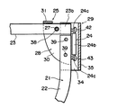
図1は本発明の刺股の一実施の形態の概要を示す正面図、図2は同上刺股の刺股本体の部分を拡大して示す図であって、両可動開閉杆が閉じている状態を示す正面図(同図A)と開いている状態を示す正面図(同図B)、図3は同上刺股本体の先端部の一部を拡大して示す縦断面図、図4は同じく平面図、図5は同上刺股本体の先端部の一部を分解して示す説明図、図6は同上刺股本体の拘束用ロープの一部を示す正面図、図7は同上開閉杆と同上ロープの係着状態を示す説明図である。 FIG. 1 is a front view showing an outline of one embodiment of the piercing of the present invention, and FIG. 2 is an enlarged view showing a portion of the piercing main body of the same piercing, showing a state in which both movable opening / closing hooks are closed. Front view (FIG. A) and front view showing the open state (FIG. B), FIG. 3 is an enlarged longitudinal sectional view showing a part of the tip of the same piercing crotch body, FIG. FIG. 5 is an explanatory view showing a part of the distal end portion of the stab body, FIG. 6 is a front view showing a part of the restraining rope of the stab body, and FIG. It is explanatory drawing which shows a state.
上記図1ないし図7において、この実施の形態(実施の形態1)の刺股は、柄部1と、この柄部1の先端部に取付けた刺股本体2とからなっている。
In FIG. 1 to FIG. 7, the piercing of this embodiment (Embodiment 1) includes a
前記柄部1は任意の素材で適当な径及び長さに形成する。この実施の形態1の柄部1はアルミ金属やプラスチックその他の素材よりなる任意本数の管11a,11b,11cを嵌合して多段式伸縮杆11で構成されている。図示の伸縮杆11は三本の管11a…11cを用いて三段式に伸縮させるように構成してあるが、前記管11a…11cの本数は任意に増減できるものである。
The
前記管11a…11cは所定部にクリックボタン12及びボタン係合孔(図示せず)を有し、伸縮杆11の最大伸長時に前記ボタン12を前記係合孔に係合させ、その位置に係脱自在に係止させるように構成してある。そして、杆11の最先端の管11aに取付部13を形成し、この取付部13を後述するように刺股本体2の二股杆21の所定部に溶着等により固定して取付けてある。前記杆11の最大径の管11cの後端には底蓋筒体14が取付けてある。なお、柄部1を一本の棒で伸縮しないように構成することも可能である。また、柄部1と刺股本体2の二股杆21とを一体的に形成することもできる。
The pipes 11a... 11c have a
前記刺股本体2は半円形状、U字形状、V字形状その他の二股状(図示では半円形状に近いU字形状)に分岐した一対の分岐杆22,22を有する二股杆21と、両分岐杆22の先端部に所定方向へ旋回自在に相対設した一対の可動開閉杆23,23と、両開閉杆23を所定の方向へ旋回させて復帰させる復帰手段24と、前記両開閉杆23の所定方向への動き(旋回)を規制するストッパー手段25と、一端を前記一方の開閉杆23の先端部に係着すると共に他端を他方の開閉杆23の先端部に係着して設けた拘束用ロープ26とを備えている。
The piercing
前記二股杆21は適当な太さ及び長さのアルミ金属やプラスチックその他の素材で構成される。実施の形態1ではアルミ金属製等の角棒材で構成されている。二股杆21の後端中央部には前記柄部1の取付部13が溶接その他の手段により固定して取付けてある。これにより、刺股本体2は、両分岐杆22を柄部1と平行する方向に向けて柄部1の先端に固定して設けられている。
The
前記両開閉杆23は適当な太さ及び長さのアルミ金属やプラスチックその他の素材で構成される。この実施の形態1の両開閉杆23はアルミ金属製等の角棒材で構成されている。また、両開閉杆23の先端23aには丸みを付してある。
The opening /
前記両開閉杆23は基端部(基端23bより幾分先端方向側の部分)を前記両分岐杆22の先端部に設けた後述する軸受部材に軸27で軸支させてそれぞれ取付けられ、軸支部(軸27)を支点として前記分岐杆22に対して起伏する方向へ旋回自在に相対設されている。そして、両開閉杆23を旋回させることにより、二股杆21の先端を両開閉杆23で開閉するように構成されている。即ち、両開閉杆23が起立して両杆23の先端23aが接近した状態の時(両開閉杆23の軸線が略同一直線上に位置した時)に二股杆21の先端は閉じられ、この状態から両開閉杆23が分岐杆22に対して倒伏する方向へ旋回することにより、両開閉杆23は離反するので、二股杆21の先端が開かれるようになっている。
The both opening /
前記両開閉杆23は、前記二股杆21の先端を閉じた位置、即ち、両開閉杆23の軸線が略同一直線上に位置した姿勢から両杆23が二股杆21の外側方向へ旋回する動きをストッパー手段25により規制されている。これにより、両開閉杆23は、両杆23に軸線が略同一直線上の位置から二股杆21の内側方向へのみ旋回自在(分岐杆に対して起伏自在)に構成されている。
The both opening /
実施の形態1は、前記開閉杆23を軸支する軸受部材28と、この部材28を分岐杆22の先端に固定して取付ける取付部材29とを備える。前記軸受部材28は図5に最も詳細に示すように、分岐杆22の太さと対応する間隔を存して平行に対設した適当な大きさの一対の軸受板30,30と、両板30の先端側における上端を直角に連結して設けたストッパー板31とを有している。前記両軸受板30はストッパー板31の後方部側における上端近くに位置させて両板30に相対設して設けた軸孔32,32と、この軸孔32の後方部側に位置させると共に上下方向に適当な間隔を存して両板30に相対向して複数組(図示では二組)設けたネジ挿入孔33,33とを有している。
また、前記取付部材29は前記両軸受板30の外側面に係合する間隔を存して対設した適当な巾及び長さの一対の取付板34,34と、この両板34の後端を直角に連結して設けた連結板35とを有している。前記両取付板34は、この板34の先端部側に位置させると共に前記ネジ挿入孔33,33と対応させて両板34に相対向して設けたネジ挿入孔36,36を有している。
The first embodiment includes a bearing
The mounting
前記両分岐杆22は、この杆22の先端部側に位置させると共に前記ネジ挿入孔33,33と対応させて前記杆22を貫通して設けたネジ挿入孔37,37を有している。また、前記両開閉杆23は、この杆23の基端部に位置させると共に前記杆23を貫通して設けた軸孔38を有している。
The two
そして、前記両軸受部材28を、前記ストッパー板31を二股杆21の内部側に向けた状態で前記両軸受板30を分岐杆22の先端部に係合させると共に、前記両取付部材29を、前記連結板35を二股杆21の外部側に向けた状態で前記両軸受板30の外側面に係合させる。そして、この状態で前記取付部材29,軸受部材28、及び分岐杆22の前記各ネジ挿入孔36,33,37を通してネジ杆39を貫挿し、ナット40を締め付けて固定してある。これにより、前記両軸受部材28は両分岐杆22の先端部に固定して設けられている。
Then, the both bearing
また、前記両開閉杆23は、前記軸孔38を前記軸受部材28の軸孔32と合致させる方向に向け、杆23の基端23bの内側面(図3において下部側面)を分岐杆22の先端面に当接させるようにすると共に杆23の外側面(図3において上部側面)を前記ストッパー板31の内側面に当接させるようにして、前記両開閉杆23の基端部を両軸受板30間に挿入する。そして、この状態で軸受部材28及び開閉杆23の前記軸孔32及び38を通して軸27を貫挿し、前記開閉杆23が回動自在になるようにナット部材41で締め付けて両開閉杆23を軸受部材28に取付けてある。これにより、両開閉杆23は基端部を軸27で軸支され、ストッパー手段25、即ち、前記ストッパー板31及び分岐杆22の先端面により二股杆21の外側方向へ旋回する動きを規制され、二股杆21の内側方向へのみ旋回自在(分岐杆に対して起伏自在)になるように構成されている。
Further, the both opening and closing
実施の形態1のストッパー手段25は、上述したように前記軸受部材28のストッパー板31と、前記分岐杆22の先端面により構成されている。
The stopper means 25 of the first embodiment is constituted by the
前記復帰手段24は両開閉杆23を分岐杆22に対して起立する方向へ旋回して復帰させるものである。実施の形態1の復帰手段24は図3に最も詳細に示すように、牽引用のコイルバネ24aで構成されている。そして、バネ24aの一端をネジ42により開閉杆23の基端部に止め着すると共に他端をネジ43により分岐杆22の先端部の適当な位置における外側面に止め着し、開閉杆23の基端面を分岐杆22側へ牽引するようにバネ力を付与してある。これにより、両開閉杆23に対して二股杆21の内側方向への押圧力が加えられると、両杆23はバネ24aの作用に抗して互いに離反する方向へ旋回し、押圧力を解除することによりバネ24aの作用により元の位置に復帰するように構成されている。
The return means 24 turns both the opening and closing
前記拘束用ロープ26は二股杆21の内側部に適当な大きさの輪44を形成する長さに形成され、ロープ26の一端を一方の開閉杆23の先端部に係着すると共に他端を他方の開閉杆23の先端部に係着して設けてある。この実施の形態1のロープ26は図6に詳細に示すように、適当な長さのワイヤーロープ45と、このロープ45に嵌合した柔軟性合成樹脂製等の被覆管46とからなっている。そして、前記両杆23の先端部に前記軸孔38と直交する方向へ貫通して設けた孔47(この孔47の外側部は図7に示すように、大径孔47aに形成されている)に前記ワイヤーロープ45の両端部を貫挿させると共に、ワイヤーロープ45の両端にナット等の係止部材48を固定して設け、この係止部材48を前記孔47の大径孔47aの縁部に係合させてワイヤーロープ45の両端を両杆23に係着させるように構成してある。
The restraining
前記構成により、両開閉杆23が分岐杆22に対して起立した状態の時、即ち、両開閉杆23で二股杆21の先端を閉じた状態の時、前記ロープ26により二股杆21の内側部にエンドレス状の輪44が形成される。この輪44の中に犯人等の目的の部位49(腕や足首等)を入れて拘束する。なお、前記被覆管46は犯人等を拘束したときに犯人等の腕や足首等を保護するために設けたものである。
With the above configuration, when both the opening and closing
実施の形態1の刺股は上記のように構成したもので、次に使用方法の一例及び作用等につき説明する。例えば刃物を持っている犯人等を制圧する際には、刃物を持っている腕49を両分岐杆22で挟むようにして刺股本体2の先端を押し付けると、図2Bに示すように、両開閉杆23は互いに離反する方向へ旋回して二股杆21の先端を開いて腕49を二股杆21の内側部へ導入する。そして、腕49が両開閉杆23の先端間を通過したときに両開閉杆23は復帰手段24のバネ作用により復帰して二股杆21の先端は閉じられるので、腕49はロープ26の輪44の中に入った状態となる。したがって、刃物を持っている腕49はロープ26の輪44で拘束され、動きを規制されるので、刃物で刺される危険性を解消して犯人等を容易に取り押さえることができる。また、犯人等の足首に前記と同様に刺股本体2の先端を押し付けると、前記と同様の動作によって足首がロープ26の輪44の中に入った状態で拘束され、動きを規制される。これにより、柄部1を引っ張る等、操作することにより犯人等を簡単に横転させることができるので、前記と同様に犯人等を容易に取り押さえることができる。
The pierced crotch according to the first embodiment is configured as described above. Next, an example of the method of use and the operation will be described. For example, when suppressing a criminal or the like holding a knife, when the tip of the piercing
また、実施の形態1のストッパー手段25は、軸受部材28のストッパー板31と、分岐杆22の先端面により構成されているので、両開閉杆23の外側方向への動き(旋回)を確実に規制することができる。さらにまた、ストッパー手段を堅牢に構成することができる。
Further, since the stopper means 25 of the first embodiment is constituted by the
なお、実施の形態1では軸受部材28と取付部材29を別体に構成した例を開示したが、両者28、29を一体化した構成を採用することもできる。
In the first embodiment, an example in which the bearing
図8は本発明の刺股の他の実施の形態(実施の形態2)の要部を示す縦断面図である。この刺股において、実施の形態1で既に説明した構成と共通する部材等には同一符号を付して説明を省略する。実施の形態2は復帰手段24の構成に特徴がある。 FIG. 8 is a longitudinal sectional view showing a main part of another embodiment (Embodiment 2) of the piercing of the present invention. In this piercing, members and the like that are the same as those already described in the first embodiment are denoted by the same reference numerals, and description thereof is omitted. The second embodiment is characterized by the configuration of the return means 24.
即ち、実施の形態2の復帰手段24は、実施の形態1の復帰手段24の前記コイルバネ24aに代え、適当な太さ及び長さのゴム紐,ゴム帯、或いはゴム条等の牽引用のゴム製等の弾性牽引体24bで構成されている。実施の形態2の弾性牽引体24bは、両端に係合部24c,24cを備えている。そして、一方の係合部24cを前記ネジ42により開閉杆23の基端面に係着すると共に他方の係合部24cを前記ネジ43により分岐杆22の先端部の適当な位置における外側面に係着し、開閉杆23の基端面を分岐杆22側へ牽引するように弾性牽引力を付与してある。他の構成は実施の形態1と同様である。
That is, the return means 24 of the second embodiment replaces the
実施の形態2の刺股は上記のように構成され、実施の形態1と同様に使用するものである。これにより、実施の形態1と同様の作用効果を奏する。
The piercing of the second embodiment is configured as described above and is used in the same manner as the first embodiment. Thereby, there exists an effect similar to
1 柄部
2 刺股本体
21 二股杆
22 分岐杆
23 可動開閉杆
24 復帰手段
25 ストッパー手段
26 拘束用ロープ
44 輪
DESCRIPTION OF
Claims (4)
前記刺股本体は、二股状に分岐した一対の分岐杆を有する二股杆と、基端部を前記両分岐杆の先端部にそれぞれ軸支させて取付けられ、前記軸支部を支点として前記分岐杆に対して起伏する方向へ旋回自在に相対設した一対の可動開閉杆と、前記両開閉杆を前記分岐杆に対して起立させる方向へ旋回させるように附勢せしめた復帰手段と、前記両開閉杆が前記二股杆の外側方向へ旋回する動きを規制するストッパー手段と、一端を前記一方の開閉杆の先端部に係着すると共に他端を前記他方の開閉杆の先端部に係着して設けた所望長さのワイヤロープ等の拘束用ロープとを備え、
前記両開閉杆は、前記両開閉杆の軸線が略同一直線上に位置した時、前記開閉杆の基端の内側面を前記分岐杆の先端面にそれぞれ当接させるようにして設けられ、
前記ストッパー手段は、前記両分岐杆の先端側に固定して設けられ、前記両開閉杆が起立する方向へ旋回して前記両開閉杆の軸線が略同一直線上に位置した時点で前記開閉杆の所定部とそれぞれ衝当するストッパー板と、前記分岐杆の先端面とで構成され、
前記両開閉杆を旋回させることにより、前記二股杆の先端を前記両開閉杆で開閉させるように構成した
ことを特徴とする、刺股。 In the piercing having the handle and the piercing body provided at the tip of the handle,
The piercing main body is attached to a bifurcated groin having a pair of bifurcated bifurcated halves and a base end portion pivotally supported on the distal ends of the bifurcated ridges. A pair of movable opening / closing rods provided relative to each other so as to be pivotable in the direction of undulation, return means for biasing the both opening / closing rods to pivot in a direction to stand up with respect to the branch rod, and the both opening / closing rods Is provided with a stopper means for restricting the movement of the two-pronged swivel outward, one end engaged with the tip of the one opening / closing rod and the other end engaged with the tip of the other opening / closing rod. And a restraining rope such as a wire rope of a desired length,
The open / close rods are provided so that the inner side surfaces of the base ends of the open / close rods are brought into contact with the distal end surfaces of the branch rods when the axes of the open / close rods are positioned on substantially the same straight line,
The stopper means is fixedly provided at the front end side of the two branch rods, and pivots in the direction in which the two open / close rods stand up, and when the axis of the both open / close rods is positioned on the substantially same straight line, the open / close rod A stopper plate that abuts against each of the predetermined portions, and a tip surface of the branch rod,
The piercing crotch is configured to open and close the ends of the bifurcated heel with the both open / close heels by turning the both open / close heels.
Priority Applications (3)
| Application Number | Priority Date | Filing Date | Title |
|---|---|---|---|
| JP2004010156A JP3984962B2 (en) | 2003-02-14 | 2004-01-19 | Piercing |
| CN2004100704542A CN1645031B (en) | 2003-02-14 | 2004-08-02 | Catcher |
| KR1020040078235A KR100815336B1 (en) | 2003-02-14 | 2004-10-01 | A tool for human capture |
Applications Claiming Priority (2)
| Application Number | Priority Date | Filing Date | Title |
|---|---|---|---|
| JP2003079099 | 2003-02-14 | ||
| JP2004010156A JP3984962B2 (en) | 2003-02-14 | 2004-01-19 | Piercing |
Publications (3)
| Publication Number | Publication Date |
|---|---|
| JP2004264014A JP2004264014A (en) | 2004-09-24 |
| JP2004264014A5 JP2004264014A5 (en) | 2005-09-29 |
| JP3984962B2 true JP3984962B2 (en) | 2007-10-03 |
Family
ID=33134276
Family Applications (1)
| Application Number | Title | Priority Date | Filing Date |
|---|---|---|---|
| JP2004010156A Expired - Lifetime JP3984962B2 (en) | 2003-02-14 | 2004-01-19 | Piercing |
Country Status (3)
| Country | Link |
|---|---|
| JP (1) | JP3984962B2 (en) |
| KR (1) | KR100815336B1 (en) |
| CN (1) | CN1645031B (en) |
Families Citing this family (9)
| Publication number | Priority date | Publication date | Assignee | Title |
|---|---|---|---|---|
| JP4611812B2 (en) * | 2005-06-10 | 2011-01-12 | 三和コンベア株式会社 | Captive |
| US7246575B2 (en) * | 2005-06-30 | 2007-07-24 | Porta Industry Co., Ltd. | Thrust fork |
| TWI290337B (en) * | 2005-08-09 | 2007-11-21 | Princo Corp | Pad conditioner for conditioning a CMP pad and method of making the same |
| JP5000908B2 (en) * | 2006-03-28 | 2012-08-15 | 株式会社オーテックジャパン | Rotating slide sheet |
| CN101865634A (en) * | 2010-06-03 | 2010-10-20 | 徐庭中 | High-efficiency multifunctional safety grabber |
| CN101893409A (en) * | 2010-06-29 | 2010-11-24 | 陆宝兴 | Telescopic police steel fork |
| CN101922891B (en) * | 2010-08-12 | 2013-01-30 | 钟庆 | Portable arrest violence preventing device |
| CN107328298B (en) * | 2016-10-31 | 2019-01-11 | 杨钶榕 | One kind is anti-riot to arrest fork |
| CN114279265A (en) * | 2021-12-22 | 2022-04-05 | 陈志贤 | Anti-separation explosion-proof fork for campus security |
Family Cites Families (3)
| Publication number | Priority date | Publication date | Assignee | Title |
|---|---|---|---|---|
| JPH07103695A (en) * | 1993-10-01 | 1995-04-18 | Nobel Kogyo Kk | Forked stretchable control rod |
| JP3085824U (en) * | 2001-11-05 | 2002-05-24 | 斉 斎藤 | Stab |
| CN2591551Y (en) * | 2002-11-28 | 2003-12-10 | 杨含澄 | Automatic capturing trouble makers electric spontoon |
-
2004
- 2004-01-19 JP JP2004010156A patent/JP3984962B2/en not_active Expired - Lifetime
- 2004-08-02 CN CN2004100704542A patent/CN1645031B/en not_active Expired - Fee Related
- 2004-10-01 KR KR1020040078235A patent/KR100815336B1/en not_active IP Right Cessation
Also Published As
| Publication number | Publication date |
|---|---|
| KR100815336B1 (en) | 2008-03-19 |
| CN1645031B (en) | 2010-04-28 |
| KR20050076588A (en) | 2005-07-26 |
| JP2004264014A (en) | 2004-09-24 |
| CN1645031A (en) | 2005-07-27 |
Similar Documents
| Publication | Publication Date | Title |
|---|---|---|
| US7246575B2 (en) | Thrust fork | |
| JP3984962B2 (en) | Piercing | |
| US20140109615A1 (en) | System, Components and Method of a Functional Multi tool Bracelet System | |
| US7216906B2 (en) | Carabiner holder | |
| US20120304473A1 (en) | Bolt cutters with breakdown handles | |
| US5136757A (en) | Releasable and adjustable fire hose clamp | |
| JPH10249070A (en) | Foldable knife provided with hole for passing through folding knife with aperture to receive lanyard | |
| FR2597901A1 (en) | SECURITY SYSTEM FOR A PERSON MOVING IN AN UNDERGROUND CHANNEL OR THE LIKE, ESPECIALLY IN A SEWER PIPE | |
| JP4806227B2 (en) | Restraint | |
| JP2005274000A (en) | Y-bar | |
| US20070094875A1 (en) | Releaseable pike pole | |
| JP6018912B2 (en) | Fish grabber | |
| US20060060040A1 (en) | Arm mounted safety cutting tool | |
| JP2004264014A5 (en) | ||
| JP2003254697A (en) | Thrust fork | |
| JP3128316U (en) | rake | |
| US20060096599A1 (en) | Pinning system to control people | |
| JP3102890U (en) | Sashimi | |
| JP5844323B2 (en) | Insulation operation rod | |
| FR2521519A1 (en) | FASTENING SYSTEM FOR VELIPLANCHISTS, UNCOUPLING MECHANISM AND UNLOCKING DEVICE THEREFOR | |
| JP2012026688A (en) | Man-catcher war fork for arresting | |
| JP7183460B1 (en) | Sasumata with rotating catch | |
| GB2389812A (en) | Cutting implement | |
| US436832A (en) | Clinton la grange | |
| JP3110827U (en) | Universal and safety joints |
Legal Events
| Date | Code | Title | Description |
|---|---|---|---|
| A521 | Request for written amendment filed |
Free format text: JAPANESE INTERMEDIATE CODE: A523 Effective date: 20050727 |
|
| A621 | Written request for application examination |
Free format text: JAPANESE INTERMEDIATE CODE: A621 Effective date: 20050802 |
|
| A977 | Report on retrieval |
Free format text: JAPANESE INTERMEDIATE CODE: A971007 Effective date: 20070130 |
|
| A131 | Notification of reasons for refusal |
Free format text: JAPANESE INTERMEDIATE CODE: A131 Effective date: 20070417 |
|
| A521 | Request for written amendment filed |
Free format text: JAPANESE INTERMEDIATE CODE: A523 Effective date: 20070524 |
|
| TRDD | Decision of grant or rejection written | ||
| A01 | Written decision to grant a patent or to grant a registration (utility model) |
Free format text: JAPANESE INTERMEDIATE CODE: A01 Effective date: 20070619 |
|
| A61 | First payment of annual fees (during grant procedure) |
Free format text: JAPANESE INTERMEDIATE CODE: A61 Effective date: 20070709 |
|
| FPAY | Renewal fee payment (event date is renewal date of database) |
Free format text: PAYMENT UNTIL: 20100713 Year of fee payment: 3 |
|
| R150 | Certificate of patent or registration of utility model |
Ref document number: 3984962 Country of ref document: JP Free format text: JAPANESE INTERMEDIATE CODE: R150 Free format text: JAPANESE INTERMEDIATE CODE: R150 |
|
| FPAY | Renewal fee payment (event date is renewal date of database) |
Free format text: PAYMENT UNTIL: 20110713 Year of fee payment: 4 |
|
| R250 | Receipt of annual fees |
Free format text: JAPANESE INTERMEDIATE CODE: R250 |
|
| FPAY | Renewal fee payment (event date is renewal date of database) |
Free format text: PAYMENT UNTIL: 20120713 Year of fee payment: 5 |
|
| R250 | Receipt of annual fees |
Free format text: JAPANESE INTERMEDIATE CODE: R250 |
|
| FPAY | Renewal fee payment (event date is renewal date of database) |
Free format text: PAYMENT UNTIL: 20120713 Year of fee payment: 5 |
|
| FPAY | Renewal fee payment (event date is renewal date of database) |
Free format text: PAYMENT UNTIL: 20130713 Year of fee payment: 6 |
|
| R250 | Receipt of annual fees |
Free format text: JAPANESE INTERMEDIATE CODE: R250 |
|
| R250 | Receipt of annual fees |
Free format text: JAPANESE INTERMEDIATE CODE: R250 |
|
| R250 | Receipt of annual fees |
Free format text: JAPANESE INTERMEDIATE CODE: R250 |
|
| R250 | Receipt of annual fees |
Free format text: JAPANESE INTERMEDIATE CODE: R250 |
|
| R250 | Receipt of annual fees |
Free format text: JAPANESE INTERMEDIATE CODE: R250 |
|
| R250 | Receipt of annual fees |
Free format text: JAPANESE INTERMEDIATE CODE: R250 |
|
| R250 | Receipt of annual fees |
Free format text: JAPANESE INTERMEDIATE CODE: R250 |
|
| R250 | Receipt of annual fees |
Free format text: JAPANESE INTERMEDIATE CODE: R250 |
|
| R250 | Receipt of annual fees |
Free format text: JAPANESE INTERMEDIATE CODE: R250 |
|
| R250 | Receipt of annual fees |
Free format text: JAPANESE INTERMEDIATE CODE: R250 |
|
| R250 | Receipt of annual fees |
Free format text: JAPANESE INTERMEDIATE CODE: R250 |
|
| R250 | Receipt of annual fees |
Free format text: JAPANESE INTERMEDIATE CODE: R250 |
|
| EXPY | Cancellation because of completion of term |